Review on the Production of Polysaccharide Aerogel Particles

 ,
,  ,
,
Abstract
:
1. Introduction
2. Engineering the Production of Droplets
- (a)
- Formation of droplets in a gaseous phase with subsequent fall in a bath that induces gelation.
- (b)
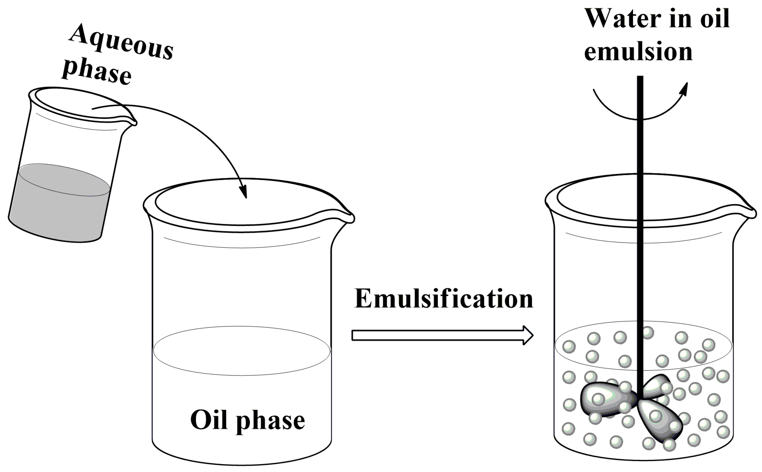
- Formation of droplets in a liquid phase which is immiscible with the biopolymer solution and on mixing leads to an emulsion.
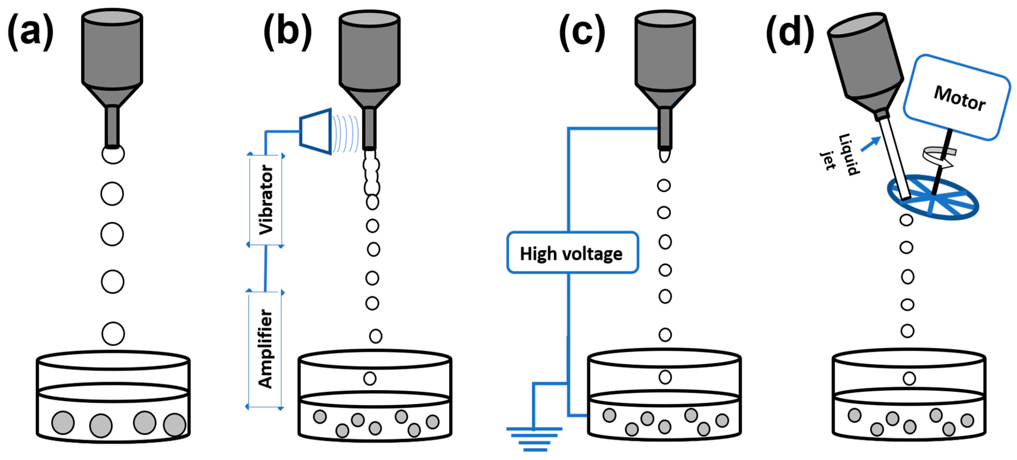
2.1. Formation of Droplets in Gaseous Phase
2.1.1. Conventional Dropping Method
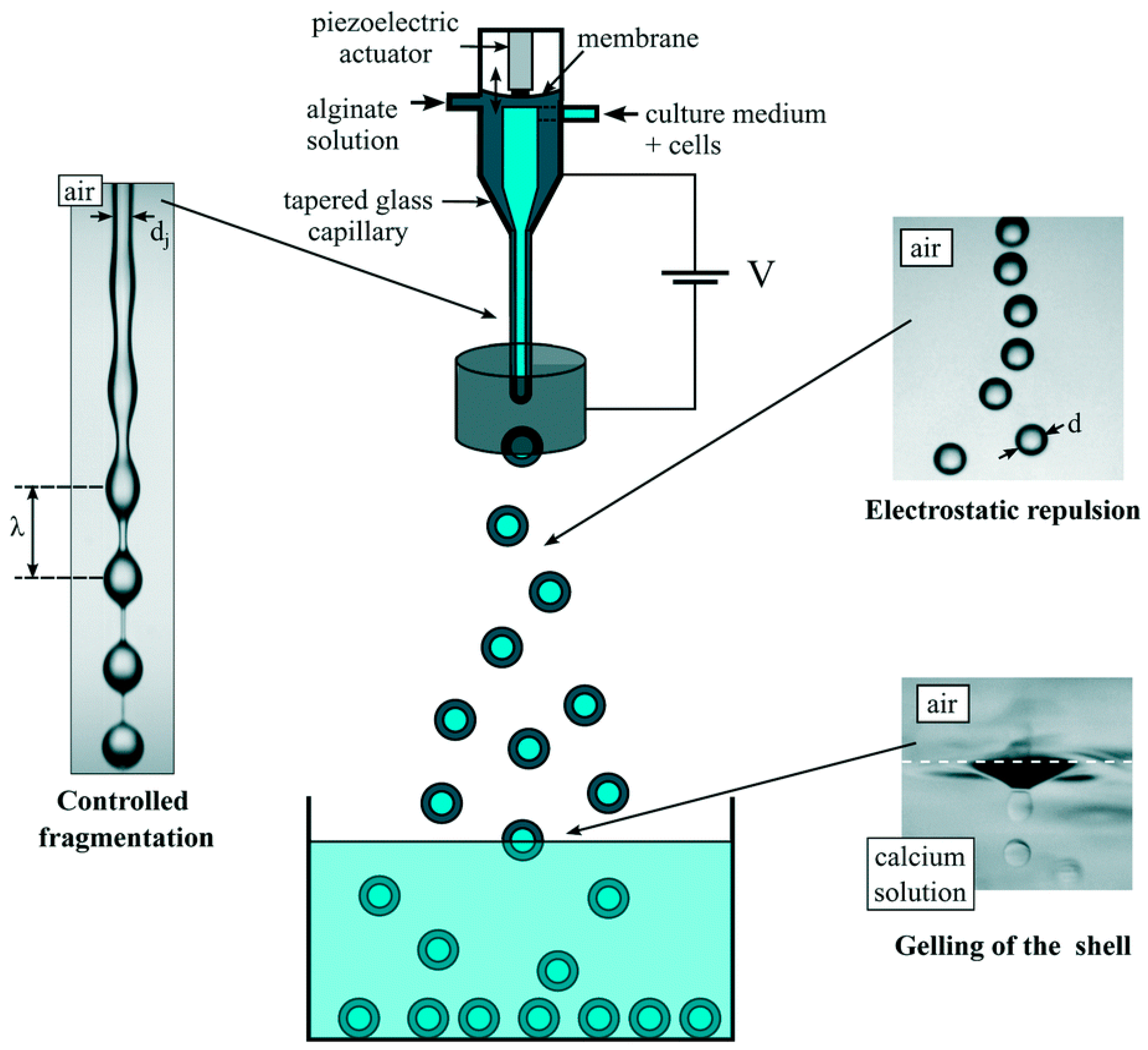
2.1.2. Vibrating Nozzle Method
2.1.3. Electrostatic Method
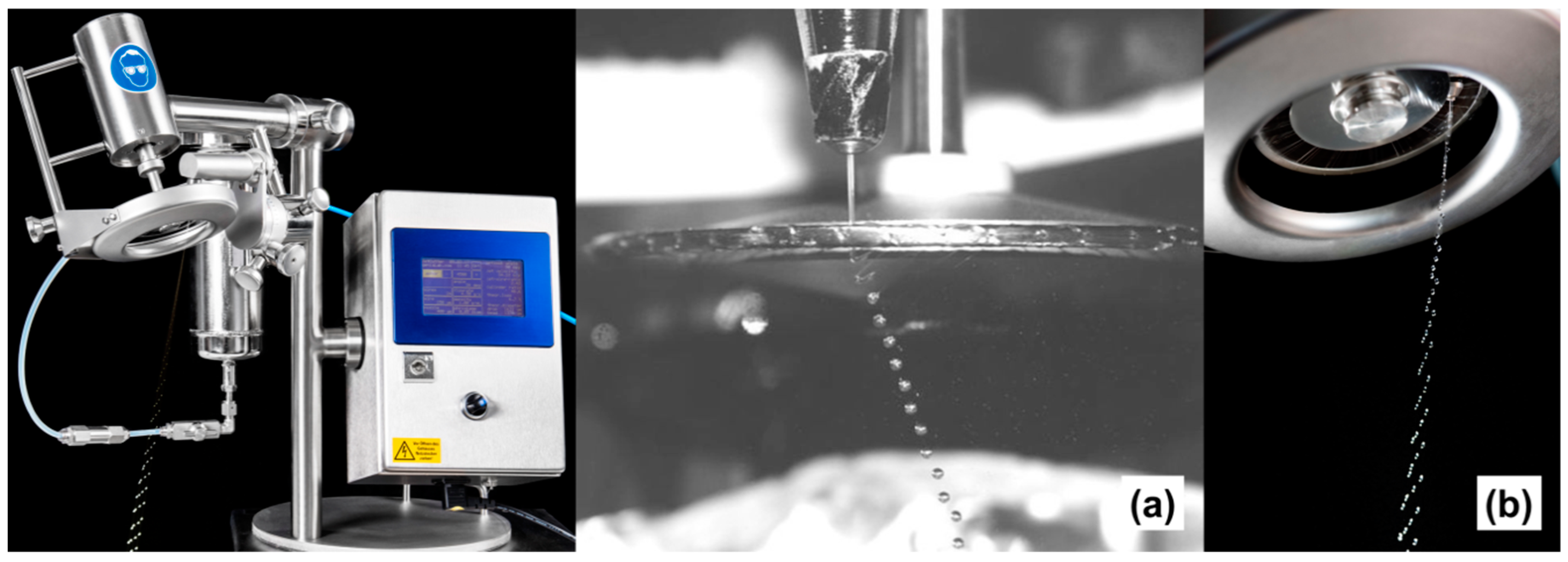
2.1.4. Mechanical Cutting Method
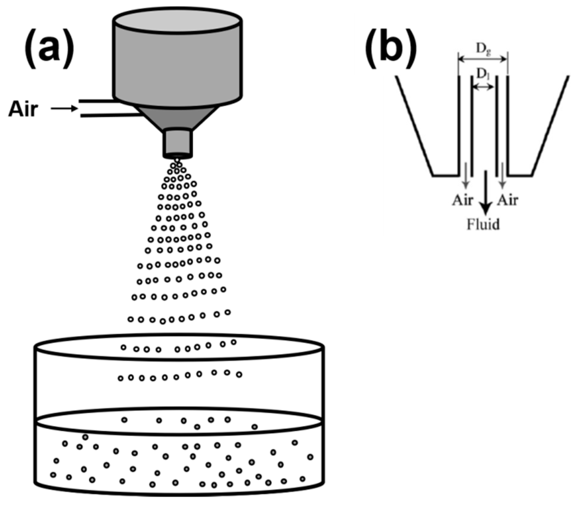
2.1.5. Spraying/Atomization
2.2. Formation of Liquid Droplets in Oil Phase
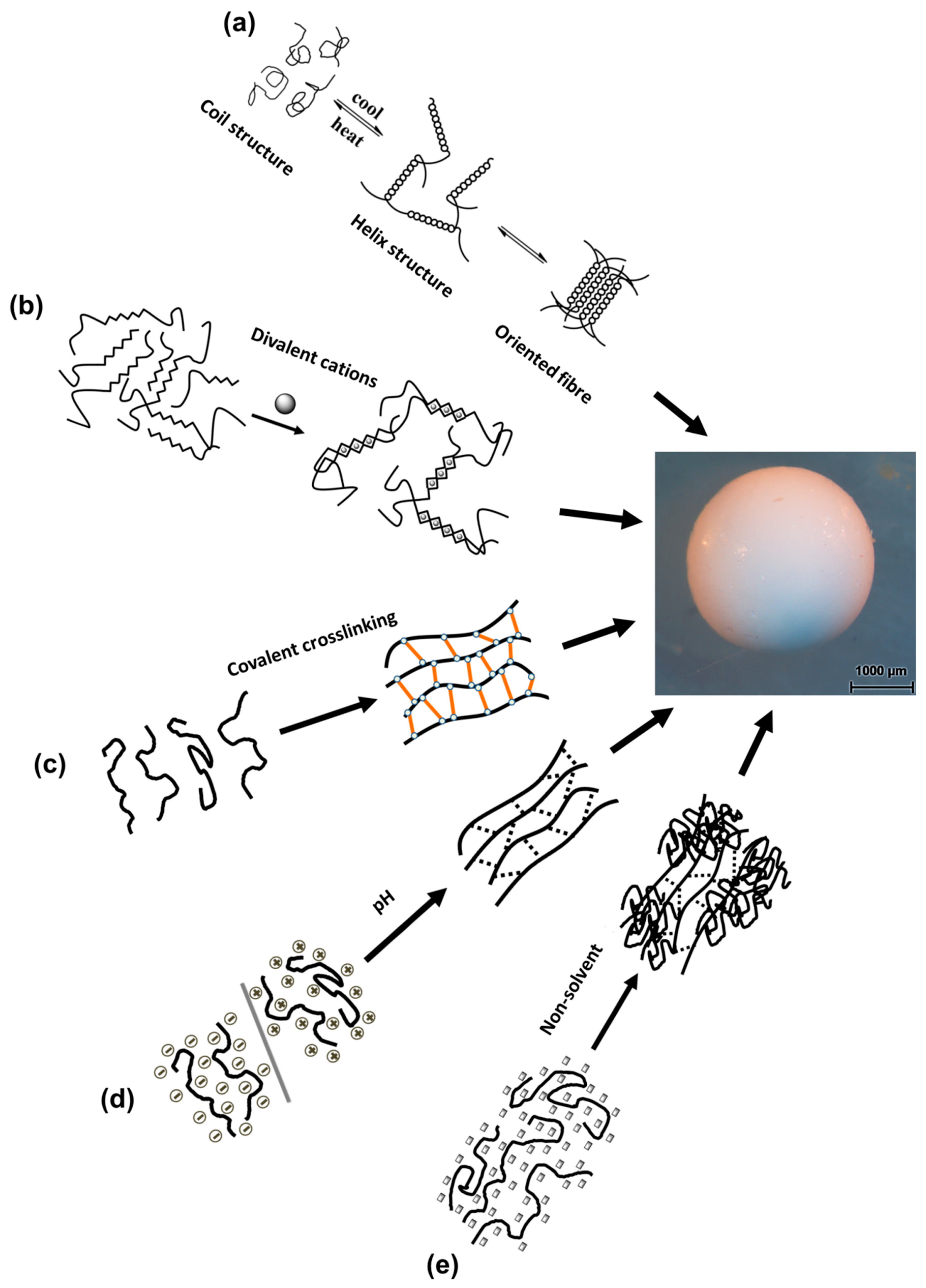
3. Gelation of Polysaccharides Droplets to Produce Gel Particles
3.1. Temperature-Induced Gelation
3.2. Crosslinking-Induced Gelation
3.2.1. Ions Crosslinking-Induced Gelation
3.2.2. Covalent Crosslinking-Induced Gelation
3.3. pH-Induced Gelation
3.4. Non-Solvent-Induced Phase Separation
4. Particle Recovery/Solvent Exchange
5. Drying of Particles
6. Characterization of Bio-Aerogels
7. State of the Art of Bio-Aerogel Particles
7.1. Agar Aerogel Particles
7.2. Alginate Aerogel Particles
7.3. Cellulose Aerogel Particles
7.4. Chitin and Chitosan Aerogel Particles
7.5. Κ-Carrageenan Aerogel Particles
7.6. Pectin Aerogel Particles
7.7. Starch Aerogel Particles
8. Applications of Polysaccharide Aerogel Particles
9. Conclusions and Perspectives on the Potential Scale-up Production of Bio-Aerogel Particles
Author Contributions
Funding
Acknowledgments
Conflicts of Interest
References
- Kistler, S.S. Coherent Expanded Aerogels and Jellies. Nature 1931, 127, 741. [Google Scholar] [CrossRef]
- Andre, N.G.; Jean, T.S. Method of Preparing Inorganic Aerogels. US 3672833 A, 27 June 1972. [Google Scholar]
- Chidambareswarapattar, C.; McCarver, P.M.; Luo, H.; Lu, H.; Sotiriou-Leventis, C.; Leventis, N. Fractal Multiscale Nanoporous Polyurethanes: Flexible to Extremely Rigid Aerogels from Multifunctional Small Molecules. Chem. Mater. 2013, 25, 3205–3224. [Google Scholar] [CrossRef]
- Leventis, N.; Sotiriou-Leventis, C.; Chidambareswarapattar, C. Porous Polyurethane Networks and Methods of Preparation. US 20140147607 A1, 29 May 2014. [Google Scholar]
- Nguyen, B.N.; Meador, M.A.B.; Scheiman, D.; McCorkle, L. Polyimide Aerogels Using Triisocyanate as Cross-linker. ACS Appl. Mater. Interfaces 2017, 9, 27313–27321. [Google Scholar] [CrossRef] [PubMed]
- Wu, S.; Du, A.; Huang, S.; Sun, W.; Xiang, Y.; Zhou, B. Solution-processable polyimide aerogels with high hydrophobicity. Mater. Lett. 2016, 176, 118–121. [Google Scholar] [CrossRef]
- Leventis, N.; Sotiriou-Leventis, C.; Chidambareswarapattar, C. Porous Nanostructured Polyimide Networks and Methods of Manufacture. US20120134909A1, 31 May 2012. [Google Scholar]
- He, S.; Zhang, Y.; Shi, X.; Bi, Y.; Luo, X.; Zhang, L. Rapid and facile synthesis of a low-cost monolithic polyamide aerogel via sol–gel technology. Mater. Lett. 2015, 144, 82–84. [Google Scholar] [CrossRef]
- Duan, Y.; Jana, S.C.; Lama, B.; Espe, M.P. Reinforcement of Silica Aerogels Using Silane-End-Capped Polyurethanes. Langmuir 2013, 29, 6156–6165. [Google Scholar] [CrossRef] [PubMed]
- Dourbash, A.; Buratti, C.; Belloni, E.; Motahari, S. Preparation and characterization of polyurethane/silica aerogel nanocomposite materials. J. Appl. Polym. Sci. 2017, 134, 44521. [Google Scholar] [CrossRef]
- Everett, D.H. Manual of symbols and terminology for physicochemical quantities and units, Appendix II: Definitions, terminology and symbols in colloid and surface chemistry. Pure Appl. Chem. 2009, 31, 577–638. [Google Scholar] [CrossRef]
- Leventis, N.; Sadekar, A.; Chandrasekaran, N.; Sotiriou-Leventis, C. Click synthesis of monolithic silicon carbide aerogels from polyacrylonitrile-coated 3D silica networks. Chem. Mater. 2010, 22, 2790–2803. [Google Scholar] [CrossRef]
- Liebner, F.; Aigner, N.; Schimper, C.; Potthast, A.; Rosenau, T. Bacterial cellulose aerogels: From lightweight dietary food to functional materials. Funct. Mater. Renew. Sources 2012, 1107, 57–74. [Google Scholar]
- Smirnova, I.; Gurikov, P. Aerogels in Chemical Engineering: Strategies Toward Tailor-Made Aerogels. Annu. Rev. Chem. Biomol. Eng. 2017, 8, 307–334. [Google Scholar] [CrossRef] [PubMed]
- Aegerter, M.A.; Leventis, N.; Koebel, M.M. Aerogels Handbook; Springer: New York, NY, USA, 2011; p. 929. [Google Scholar]
- Pierre, A.C.; Pajonk, G.M. Chemistry of Aerogels and Their Applications. Chem. Rev. 2002, 102, 4243–4265. [Google Scholar] [CrossRef] [PubMed]
- Gesser, H.D.; Goswami, P.C. Aerogels and Related Porous Materials. Chem. Rev. 1989, 89, 765–788. [Google Scholar] [CrossRef]
- Hüsing, N.; Schubert, U. Aerogels-Airy Materials: Chemistry, Structure, and Properties. Angew. Chem. Int. Ed. 1998, 37, 22–45. [Google Scholar] [CrossRef]
- García-González, C.A.; Alnaief, M.; Smirnova, I. Polysaccharide-based aerogels—Promising biodegradable carriers for drug delivery systems. Carbohydr. Polym. 2011, 86, 1425–1438. [Google Scholar] [CrossRef]
- Lavoine, N.; Bergström, L. Nanocellulose-based foams and aerogels: Processing, properties, and applications. J. Mater. Chem. A 2017, 5, 16105–16117. [Google Scholar] [CrossRef]
- France, K.J.D.; Hoare, T.; Cranston, E.D. Review of Hydrogels and Aerogels Containing Nanocellulose. Chem. Mater. 2017, 29, 4609–4631. [Google Scholar] [CrossRef]
- Liebner, F.; Pircher, N.; Schimper, C.; Haimer, E.; Rosenau, T. Aerogels: Cellulose-Based. In Encyclopedia of Biomedical Polymers and Polymeric Biomaterials; Mishra, M., Ed.; Taylor and Francis: Boca Raton, FL, USA, 2015; Volume 11, pp. 37–75. [Google Scholar]
- Long, L.-Y.; Weng, Y.-X.; Wang, Y.-Z. Cellulose Aerogels: Synthesis, Applications, and Prospects. Polymers 2018, 10, 623. [Google Scholar] [CrossRef]
- Zhao, S.; Malfait, W.J.; Guerrero-Alburquerque, N.; Koebel, M.M.; Nyström, G. Biopolymer Aerogels and Foams: Chemistry, Properties, and Applications. Angew. Chem. Int. Ed. 2018, 57, 2–31. [Google Scholar] [CrossRef] [PubMed]
- Kistler, S.S. Coherent Expanded-Aerogels. J. Phys. Chem. 1932, 36, 52–64. [Google Scholar] [CrossRef]
- Stamm, A.J.; Tarkow, H. The Penetration of Cellulose Fibers. J. Phys. Chem. 1950, 54, 745–753. [Google Scholar] [CrossRef]
- Alinče, B. Porosity of swollen solvent-exchanged cellulose and its collapse during final liquid removal. Colloid Polym. Sci. 1975, 253, 720–729. [Google Scholar] [CrossRef]
- Weatherwax, R.C. Collapse of cell-wall pores during drying of cellulose. J. Colloid Interface Sci. 1977, 62, 432–446. [Google Scholar] [CrossRef]
- Ookuma, S.; Igarashi, K.; Hara, M.; Aso, K.; Yoshidome, H.; Nakayama, H.; Suzuki, K.; Nakajima, K. Porous Ion-Exchanged Fine Cellulose Particles, Method for Production Thereof, and Affinity Carrier. US5196527A, 4 May 1988. [Google Scholar]
- Ratke, L. Monoliths and fibrous cellulose aerogels. In Aerogels Handbook; Aegerter, M.A., Leventis, N., Koebel, M.M., Eds.; Springer: New York, NY, USA, 2011; p. 173. [Google Scholar]
- Smirnova, I. Pharmaceutical applications of aerogels. In Aerogels Handbook, 1st ed.; Aegerter, M.A., Leventis, N., Koebel, M.M., Eds.; Springer: New York, NY, USA, 2011; p. 695. [Google Scholar]
- Innerlohinger, J.; Weber, H.K.; Kraft, G. Aerocellulose: Aerogels and aerogel-like materials made from cellulose. Macromol. Symp. 2006, 244, 126–135. [Google Scholar] [CrossRef]
- Gavillon, R.; Budtova, T. Aerocellulose: New highly porous cellulose prepared from cellulose-NaOH aqueous solutions. Biomacromolecules 2008, 9, 269–277. [Google Scholar] [CrossRef] [PubMed]
- Liebner, F.; Haimer, E.; Wendland, M.; Neouze, M.-A.; Schlufter, K.; Miethe, P.; Heinze, T.; Potthast, A.; Rosenau, T. Aerogels from unaltered bacterial cellulose: Application of scCO2 drying for the preparation of shaped, ultra-lightweight cellulosic aerogels. Macromol. Biosci. 2010, 10, 349–352. [Google Scholar] [CrossRef] [PubMed]
- Quignard, F.; Valentin, R.; Renzo, F.D. Aerogel materials from marine polysaccharides. New J. Chem. 2008, 32, 1300–1310. [Google Scholar] [CrossRef]
- Tan, C.; Fung, B.M.; Newman, J.K.; Vu, C. Organic aerogels with very high impact strength. Adv. Mater. 2001, 13, 644–646. [Google Scholar] [CrossRef]
- Jin, H.; Nishiyama, Y.; Wada, M.; Kuga, S. Nanofibrillar cellulose aerogels. Colloids Surf. A 2004, 240, 63–67. [Google Scholar] [CrossRef]
- Pääkkö, M.; Vapaavuori, J.; Silvennoinen, R.; Kosonen, H.; Ankerfors, M.; Lindström, T.; Berglund, L.A.; Ikkala, O. Long and entangled native cellulose I nanofibers allow flexible aerogels and hierarchically porous templates for functionalities. Soft Matter 2008, 4, 2492–2499. [Google Scholar] [CrossRef]
- Aaltonen, O.; Jauhiainen, O. The preparation of lignocellulosic aerogels from ionic liquid solutions. Carbohydr. Polym. 2009, 75, 125–129. [Google Scholar] [CrossRef]
- Liebner, F.; Haimer, E.; Potthast, A.; Rosenau, T. Cellulosic Aerogels. In Polysaccharide Building Blocks: A Sustainable Approach to the Development of Renewable Biomaterials, 1st ed.; Habibi, Y., Lucia, L.A., Eds.; John Wiley & Sons, Inc.: Hoboken, NJ, USA, 2012. [Google Scholar]
- Heath, L.; Thielemans, W. Cellulose nanowhisker aerogels. Green Chem. 2010, 12, 1448–1453. [Google Scholar] [CrossRef]
- Heath, L.; Zhu, L.; Thielemans, W. Chitin Nanowhisker Aerogels. ChemSusChem 2013, 6, 537–544. [Google Scholar] [CrossRef] [PubMed] [Green Version]
- Nguyen, S.T.; Feng, J.; Ng, S.K.; Wong, J.P.W.; Tan, V.B.C.; Duong, H.M. Advanced thermal insulation and absorption properties of recycled cellulose aerogels. Colloids Surf. Physicochem. Eng. Asp. 2014, 445, 128–134. [Google Scholar] [CrossRef]
- Rudaz, C.; Courson, R.; Bonnet, L.; Calas-Etienne, S.; Sallée, H.; Budtova, T. Aeropectin: Fully biomass-based mechanically strong and thermal superinsulating aerogel. Biomacromolecules 2014, 15, 2188–2195. [Google Scholar] [CrossRef] [PubMed]
- Cai, J.; Liu, S.; Feng, J.; Kimura, S.; Wada, M.; Kuga, S.; Zhang, L. Cellulose-Silica Nanocomposite Aerogels by In Situ Formation of Silica in Cellulose Gel. Angew. Chem. Int. Ed. 2012, 124, 2118–2121. [Google Scholar] [CrossRef]
- Fischer, F.; Rigacci, A.; Pirard, R.; Berthon-Fabry, S.; Achard, P. Cellulose-based aerogels. Polymer 2006, 47, 7636–7645. [Google Scholar] [CrossRef]
- Grishechko, L.I.; Amaral-Labat, G.; Szczurek, A.; Fierro, V.; Kuznetsov, B.N.; Pizzi, A.; Celzard, A. New tannin-lignin aerogels. Ind. Crops Prod. 2013, 41, 347–355. [Google Scholar] [CrossRef]
- Gurikov, P.; Raman, S.; Weinrich, D.; Fricke, M.; Smirnova, I. A novel approach to alginate aerogels: Carbon dioxide induced gelation. RSC Adv. 2015, 5, 7812–7818. [Google Scholar] [CrossRef]
- Druel, L.; Bardl, R.; Vorwerg, W.; Budtova, T. Starch Aerogels: A Member of the Family of Thermal Superinsulating Materials. Biomacromolecules 2017, 18, 4232–4239. [Google Scholar] [CrossRef] [PubMed]
- Groult, S.; Budtova, T. Thermal conductivity/structure correlations in thermal super-insulating pectin aerogels. Carbohyd. Polym. 2018, 196, 73–81. [Google Scholar] [CrossRef] [PubMed]
- Demilecamps, A.; Alves, M.; Rigacci, A.; Reichenauer, G.; Budtova, T. Nanostructured interpenetrated organic-inorganic aerogels with thermal superinsulating properties. J. Non-Cryst. Solids 2016, 452, 259–265. [Google Scholar] [CrossRef]
- Quraishi, S.; Martins, M.; Barros, A.A.; Gurikov, P.; Raman, S.P.; Smirnova, I.; Duarte, A.R.C.; Reis, R.L. Novel non-cytotoxic alginate-lignin hybrid aerogels as scaffolds for tissue engineering. J. Supercrit. Fluids 2015, 105, 1–8. [Google Scholar] [CrossRef]
- Betz, M.; García-González, C.A.; Subrahmanyam, R.P.; Smirnova, I.; Kulozik, U. Preparation of novel whey protein-based aerogels as drug carriers for life science applications. J. Supercrit. Fluids 2012, 72, 111–119. [Google Scholar] [CrossRef]
- Monakhova, Y.; Agulhon, P.; Quignard, F.; Tanchoux, N.; Tichit, D. New mixed lanthanum- and alkaline-earth cation-containing basic catalysts obtained by an alginate route. Catal. Today 2012, 189, 28–34. [Google Scholar] [CrossRef]
- Kayser, H.; Müller, C.R.; García-González, C.A.; Smirnova, I.; Leitner, W.; Domínguez de María, P. Dried chitosan-gels as organocatalysts for the production of biomass-derived platform chemicals. Appl. Catal. A Gen. 2012, 445–446, 180–186. [Google Scholar] [CrossRef]
- Mallepally, R.R.; Bernard, I.; Marin, M.A.; Ward, K.R.; McHugh, M.A. Superabsorbent alginate aerogels. J. Supercrit. Fluids 2013, 79, 202–208. [Google Scholar] [CrossRef]
- Escudero, R.R.; Robitzer, M.; Di Renzo, F.; Quignard, F.O. Alginate aerogels as adsorbents of polar molecules from liquid hydrocarbons: Hexanol as probe molecule. Carbohydr. Polym. 2009, 75, 52–57. [Google Scholar] [CrossRef]
- Trens, P.; Valentin, R.; Quignard, F. Cation enhanced hydrophilic character of textured alginate gel beads. Colloids Surf. Physicochem. Eng. Asp. 2007, 296, 230–237. [Google Scholar] [CrossRef]
- Budarin, V.; Clark, J.H.; Hardy, J.J.E.; Luque, R.; Milkowski, K.; Tavener, S.J.; Wilson, A.J. Starbons: New Starch-Derived Mesoporous Carbonaceous Materials with Tunable Properties. Angew. Chem. Int. Ed. 2006, 45, 3782–3786. [Google Scholar] [CrossRef] [PubMed]
- White, R.J.; Budarin, V.L.; Clark, J.H. Pectin-Derived Porous Materials. Chem. Eur. J. 2009, 16, 1326–1335. [Google Scholar] [CrossRef] [PubMed]
- Guilminot, E.; Gavillon, R.; Chatenet, M.; Berthon-Fabry, S.; Rigacci, A.; Budtova, T. New nanostructured carbons based on porous cellulose: Elaboration, pyrolysis and use as platinum nanoparticles substrate for oxygen reduction electrocatalysis. J. Power Sources 2008, 185, 717–726. [Google Scholar] [CrossRef]
- Demilecamps, A.; Beauger, C.; Hildenbrand, C.; Rigacci, A.; Budtova, T. Cellulose-silica aerogels. Carbohydr. Polym. 2015, 122, 293–300. [Google Scholar] [CrossRef] [PubMed]
- Agulhon, P.; Constant, S.; Chiche, B.; Lartigue, L.; Larionova, J.; Di Renzo, F.; Quignard, F. Controlled synthesis from alginate gels of cobalt-manganese mixed oxide nanocrystals with peculiar magnetic properties. Catal. Today 2012, 189, 49–54. [Google Scholar] [CrossRef]
- Groult, S.; Budtova, T. Tuning structure and properties of pectin aerogels. Eur. Polym. J. 2018, 108, 250–261. [Google Scholar] [CrossRef]
- Primo, A.; Liebel, M.; Quignard, F. Palladium Coordination Biopolymer: A Versatile Access to Highly Porous Dispersed Catalyst for Suzuki Reaction. Chem. Mater. 2009, 21, 621–627. [Google Scholar] [CrossRef]
- Kadib, A.E.; Molvinger, K.; Guimon, C.; Quignard, F.; Brunel, D. Design of Stable Nanoporous Hybrid Chitosan/Titania as Cooperative Bifunctional Catalysts. Chem. Mater. 2008, 20, 2198–2204. [Google Scholar] [CrossRef]
- Ricci, A.; Bernardi, L.; Gioia, C.; Vierucci, S.; Robitzer, M.; Quignard, F. Chitosan aerogel: A recyclable, heterogeneous organocatalyst for the asymmetric direct aldol reaction in water. Chem. Commun. 2010, 46, 6288–6290. [Google Scholar] [CrossRef] [PubMed]
- Frindy, S.; Kadib, A.E.; Lahcini, M.; Primo, A.; García, H. Copper Nanoparticles Stabilized in a Porous Chitosan Aerogel as a Heterogeneous Catalyst for C-S Cross-coupling. ChemCatChem 2015, 20, 3307–3315. [Google Scholar] [CrossRef]
- Levy-Ontman, O.; Biton, S.; Shlomov, B.; Wolfson, A. Renewable Polysaccharides as Supports for Palladium Phosphine Catalysts. Polymers 2018, 10, 659. [Google Scholar] [CrossRef]
- Chan, E.-S.; Lee, B.-B.; Ravindra, P.; Poncelet, D. Prediction models for shape and size of ca-alginate macrobeads produced through extrusion dripping method. J. Colloid Interface Sci. 2009, 338, 63–72. [Google Scholar] [CrossRef] [PubMed]
- Bidoret, A.M.E.; De Smet, B.P.; Poncelet, D. Cell Microencapsulation: Dripping Methods. In Cell Microencapsulation. Methods in Molecular Biology; Opara, E.C., Ed.; Humana Press: New York, NY, USA, 2017; Volume 1479, pp. 43–55. [Google Scholar]
- Ghosal, S.K.; Talukdar, P.; Pal, T.K. Standardization of a newly designed vibrating capillary apparatus for the preparation of microcapsules. Chem. Eng. Technol. 1993, 16, 395–398. [Google Scholar] [CrossRef]
- Gaudio, P.D.; Colombo, P.; Colombo, G.; Russo, P.; Sonvico, F. Mechanisms of formation and disintegration of alginate beads obtained by prilling. Int. J. Pharm. 2005, 302, 1–9. [Google Scholar] [CrossRef] [PubMed]
- De Cicco, F.; Russo, P.; Reverchon, E.; García-González, C.A.; Aquino, R.P.; Del Gaudio, P. Prilling and supercritical drying: A successful duo to produce core-shell polysaccharide aerogel beads for wound healing. Carbohydr. Polym. 2016, 147, 482–489. [Google Scholar] [CrossRef] [PubMed]
- Poncelet, D.; Neufeld, R.; Bugarski, B.; Amsden, B.G.; Zhu, J.; Goosen, M.F.A. A Parallel plate electrostatic droplet generator: Parameters affecting microbead size. Appl. Microbiol. Biotechnol. 1994, 42, 251–255. [Google Scholar] [CrossRef]
- Bugarski, B.; Li, Q.; Goosen, M.F.A.; Poncelet, D.; Neufeld, R.J.; Vunjak, G. Electrostatic droplet generation: Mechanism of polymer droplet formation. AICHE J. 1994, 40, 1026–1031. [Google Scholar] [CrossRef]
- Halle, J.P.; Leblond, F.A.; Pariseau, J.F.; Jutras, P.; Bradant, M.J.; Lepage, Y. Studies on small (<300 micrometers) Microcapsules. Parameters Governing the Production of Alginate Beads by High-Voltage Electrostatic Pulses. Cell. Transplant. 1994, 3, 365–372. [Google Scholar] [PubMed]
- Doméjean, H.; Pierre, M.d.l.M.S.; Funfak, A.; Atrux-Tallau, N.; Alessandri, K.; Nassoy, P.; Bibette, J.; Bremond, N. Controlled production of sub-millimeter liquid core hydrogel capsules for parallelized 3D cell culture. Lab. Chip 2017, 17, 110–119. [Google Scholar] [CrossRef] [PubMed]
- Enayati, M.; Ahmad, Z.; Stride, E.; Edirisinghe, M. One-step electrohydrodynamic production of drug-loaded micro- and nanoparticles. J. R. Soc. Interface 2010, 7, 667–675. [Google Scholar] [CrossRef] [PubMed] [Green Version]
- Vorlop, K.-D.; Breford, J. Verfahren und Vorrichtung zur Herstellung von Teilchen aus Einem Flüssigen Medium. Patent DE4424998A1, 1 February 1996. [Google Scholar]
- Prüsse, U.; Bilancetti, L.; Bučko, M.; Bugarski, B.; Bukowski, J.; Gemeiner, P.; Lewińska, D.; Manojlovic, V.; Massart, B.; Nastruzzi, C.; et al. Comparison of different technologies for alginate beads production. Chem. Pap. 2008, 62, 364. [Google Scholar] [CrossRef]
- Prüsse, U.; Jahnz, U.; Wittlich, P.; Breford, J.; Vorlop, K.-D. Bead production with JetCutting and rotating disc/nozzle technologies. Landbauforschung Völkenrode 2002, SH241, 1–10. [Google Scholar]
- Prüsse, U.; Jahnz, U.; Wittlich, P.; Vorlop, K.-D. Scale-up of the JetCutter technology. Chem. Ind. 2003, 57, 636–640. [Google Scholar] [CrossRef]
- Prüsse, U.; Fox, B.; Kirchhoff, M.; Bruske, F.; Breford, J.; Vorlop, K.-D. New Process (Jet Cutting Method) for the Production of Spherical Beads from Highly Viscous Polymer Solutions. Chem. Eng. Technol. 1998, 21, 29–33. [Google Scholar] [CrossRef]
- Prüsse, U.; Bruske, F.; Breford, J.; Vorlop, K.-D. Improvement of the Jet Cutting Method for the Preparation of Spherical Particles from Viscous Polymer Solutions. Chem. Eng. Technol. 1998, 21, 153–157. [Google Scholar] [CrossRef]
- Perrechil, F.A.; Sato, A.C.K.; Cunha, R.L. k-Carrageenan–sodium caseinate microgel production by atomization: Critical analysis of the experimental procedure. J. Food Eng. 2011, 104, 123–133. [Google Scholar] [CrossRef]
- Lykov, M.V.; Leonchik, B.I. Raspylitel’nye Sushilki. Osnovy Teorii i Rascheta; Mashinostroenie: Moscow, Russia, 1966. [Google Scholar]
- Mushtaev, V.I.; Ulyanov, V.M. Sushka Dispersnykh Materialov; Khimiya: Moscow, Russia, 1988. [Google Scholar]
- Havkin, Y.I. Centrobezhnye Forsunki; Mashinostroenie: Leningrad, Russia, 1976; p. 168. [Google Scholar]
- Lund, M.T.; Sojka, P.E.; Lefebvre, A.H.; Gosselin, P.G. Effervescent atomization at low mass flow rates. Part 1: The influence of Surface Tension. At. Sprays 1993, 3, 77–89. [Google Scholar] [CrossRef]
- Lightfoot, M.D.A. Fundamental classification of atomization processes. At. Sprays 2009, 19, 1065–1104. [Google Scholar] [CrossRef]
- Walzel, P. Atomizing of liquids. Chem. Ing. Tech. 1990, 62, 983–994. [Google Scholar] [CrossRef]
- Lefebvre, A.H. Atomization and Sprays; Taylor & Francis: New York, NY, USA, 1989; p. 423. [Google Scholar]
- Cai, H.; Sharma, S.; Liu, W.; Mu, W.; Liu, W.; Zhang, X.; Deng, Y. Aerogel Microspheres from Natural Cellulose Nanofibrils and Their Application as Cell Culture Scaffold. Biomacromolecules 2014, 15, 2540–2547. [Google Scholar] [CrossRef] [PubMed]
- Zhang, F.; Ren, H.; Dou, J.; Tong, G.; Deng, Y. Cellulose Nanofibril Based-Aerogel Microreactors: A High Efficiency and Easy Recoverable W/O/W Membrane Separation System. Sci. Rep. 2017, 7, 40096. [Google Scholar] [CrossRef] [PubMed] [Green Version]
- Boyd, J.; Parkinson, C.; Sherman, P. Factors affecting emulsion stability, and the HLB concept. J. Colloid Interface Sci. 1972, 41, 359–370. [Google Scholar] [CrossRef]
- Arshady, R. Albumin microspheres and microcapsules: Methodology of manufacturing techniques. J. Control. Release 1990, 14, 111–131. [Google Scholar] [CrossRef]
- Poncelet, D.; Lencki, R.; Beaulieu, C.; Halle, J.P.; Neufeld, R.J.; Fournier, A. Production of alginate beads by emulsification/internal gelation. I. Methodology. Appl. Microbiol. Biotechnol. 1992, 38, 39–45. [Google Scholar] [CrossRef] [PubMed]
- Hemrajani Ramesh, R.; Tatterson Gary, B. Mechanically Stirred Vessels. In Handbook of Industrial Mixing; Paul, E.L., Atiemo-Obeng, V.A., Kresta, S.M., Eds.; John Wiley & Sons, Inc.: Hoboken, NJ, USA, 2004; pp. 345–390. [Google Scholar]
- Alnaief, M.; Smirnova, I. In situ production of spherical aerogel microparticles. J. Supercrit. Fluids 2011, 55, 1118–1123. [Google Scholar] [CrossRef]
- Almeida-Rivera, C.; Bongers, P. Modelling and experimental validation of emulsification processes in continuous rotor–stator units. Comput. Chem. Eng. 2010, 34, 592–597. [Google Scholar] [CrossRef]
- Gamini, A.; Civitarese, G.; Cesàro, A.; Delben, F.; Paoletti, S. gelation mechanism of ionic polysaccharides. Makromol. Chem. Macromol. Symp. 1990, 39, 143–154. [Google Scholar] [CrossRef]
- Rinaudo, M. Gelation of polysaccharides. J. Intell. Mater. Syst. Struct. 1993, 4, 210–215. [Google Scholar] [CrossRef]
- Tako, M. The principle of polysaccharide gels. Adv. Biosci. Biotechnol. 2015, 6, 22–26. [Google Scholar] [CrossRef]
- Morris, E.R. Molecular interactions in polysaccharide gelation. Br. Polym. J. 1986, 18, 14–21. [Google Scholar] [CrossRef]
- Tako, M.; Tamaki, Y.; Teruya, T.; Takeda, Y. The Principles of Starch Gelatinization and Retrogradation. Food Nutr. Sci. 2014, 5, 280–291. [Google Scholar] [CrossRef]
- Zobel, H.F.; Stephen, A.M. Starch: Structure, Analysis, and Applicaiton. In Food Polysaccharides and Their Applications, 2nd ed.; Stephen, A.M., Phillips, G.O., Williams, P.A., Eds.; CRC Press, Taylor & Francis Group: New York, NY, USA, 2006. [Google Scholar]
- Braudo, E.E.; Muratalieva, I.R.; Plashchina, I.G.; Tolstoguzov, V.B.; Markovich, I.S. Studies on the mechanisms of gelation of kappa-carrageenan and agarose. Colloid Polym. Sci. 1991, 269, 1148–1156. [Google Scholar] [CrossRef]
- Gurikov, P.; Smirnova, I. Non-Conventional Methods for Gelation of Alginate. Gels 2018, 4, 14. [Google Scholar] [CrossRef]
- Roy, C.; Budtova, T.; Navard, P. Rheological Properties and Gelation of Aqueous Cellulose-NaOH Solutions. Biomacromolecules 2003, 4, 259–264. [Google Scholar] [CrossRef] [PubMed]
- Cai, J.; Zhang, L. Unique Gelation Behavior of Cellulose in NaOH/Urea Aqueous Solution. Biomacromolecules 2006, 7, 183–189. [Google Scholar] [CrossRef] [PubMed]
- Liu, W.; Budtova, T.; Navard, P. Influence of ZnO on the properties of dilute and semi-dilute cellulose-NaOH-water solutions. Cellulose 2011, 18, 911–920. [Google Scholar] [CrossRef] [Green Version]
- Budtova, T.; Navard, P. Cellulose in NaOH-water based solvents: A review. Cellulose 2016, 23, 5–55. [Google Scholar] [CrossRef]
- Syverud, K.; Kirsebom, H.; Hajizadeh, S.; Chinga-Carrasco, G. Cross-linking cellulose nanofibrils for potential elastic cryo-structured gels. Nanoscale Res. Lett. 2011, 6, 626. [Google Scholar] [CrossRef] [PubMed] [Green Version]
- Piculell, L. Gelling Carrageenans. In Food Polysaccharides and Their Applications, 2nd ed.; Stephen, A.M., Phillips, G.O., Williams, P.A., Eds.; CRC Press, Taylor & Francis Group: New York, NY, USA, 2006. [Google Scholar]
- Belton, P.S.; Morris, V.J.; Tanner, S.F. Interaction of group I cations with iota, kappa and lambda carrageenans studied by multinuclear nmr. Int. J. Biol. Macromol. 1985, 7, 53–56. [Google Scholar] [CrossRef]
- Nilsson, S.; Piculell, L. Helix-coil transitions of ionic polysaccharides analyzed within the Poisson-Boltzmann cell model. 4. Effects of site-specific counterion binding. Macromolecules 1991, 13, 3804–3811. [Google Scholar] [CrossRef]
- Zhang, W.; Piculell, L.; Nilsson, S. Effects of specific anion binding on the helix-coil transition of lower charged carrageenans. NMR data and conformational equilibria analyzed within the Poisson-Boltzmann cell model. Macromolecules 1992, 25, 6165–6172. [Google Scholar] [CrossRef]
- Shu, X.Z.; Zhu, K.J. Chitosan/gelatin microspheres prepared by modified emulsification and ionotropic gelation. J. Microencapsul. 2001, 18, 237–245. [Google Scholar] [PubMed]
- Vorlop, K.-D.; Klein, J. Formation of spherical chitosan biocatalysts by ionotropic gelation. Biotechnol. Lett. 1981, 3, 9–14. [Google Scholar] [CrossRef]
- Shu, X.Z.; Zhu, K.J. A novel approach to prepare tripolyphosphate/chitosan complex beads for controlled release drug delivery. Int. J. Pharm. 2000, 201, 51–58. [Google Scholar] [CrossRef]
- Toft, K.; Grasdalen, H.; Smidsrod, O. Synergistic Gelation of Alginates and Pectins. In Chemistry and Function of Pectins; Fishman, M.L., Jen, J.J., Eds.; ACS Symposium Series; American Chemical Society: Washington, DC, USA, 1986; Volume 310, pp. 117–132. [Google Scholar]
- Ciolacu, D.; Rudaz, C.; Vasilescu, M.; Budtova, T. Physically and chemically cross-linked cellulose cryogels: Structure, properties and application for controlled release. Carbohydr. Polym. 2016, 151, 392–400. [Google Scholar] [CrossRef] [PubMed]
- Bates, I.; Maudru, E.; Phillips, D.A.S.; Renfrew, A.H.M.; Su, Y.; Xu, J. Cross-linking agents for the protection of lyocell against fibrillation: Synthesis, application and technical assessment of 2,4-diacrylamidobenzenesulphonic acid. Color. Technol. 2004, 120, 293–300. [Google Scholar] [CrossRef]
- Hassan, E.E.; Parish, R.C.; Gallo, J.M. Optimized Formulation of Magnetic Chitosan Microspheres Containing the Anticancer Agent, Oxantrazole. Pharm. Res. 1992, 9, 390–397. [Google Scholar] [CrossRef] [PubMed]
- Denkbas, E.B.; Seyyal, M.; Piskin, E. 5-Fluorouracil loaded chitosan microspheres for chemoembolization. J. Microencapsul. 1999, 16, 741–749. [Google Scholar] [PubMed]
- Dini, E.; Alexandridou, S.; Kiparissides, C. Synthesis and characterization of cross-linked chitosan microspheres for drug delivery applications. J. Microencapsul. 2003, 20, 375–385. [Google Scholar] [CrossRef] [PubMed]
- Emir Baki, D.; Mehmet, O.; Ebru, K.; Özdemir, N. Human Serum Albumin (HSA) Adsorption with Chitosan Microspheres. J. Appl. Polym. Sci. 2002, 86, 3035–3039. [Google Scholar]
- Pavanetto, F.; Perugini, P.; Conti, B.; Modena, T.; Genta, I. Evaluation of process parameters involved in chitosan microsphere preparation by the o/w/o multiple emulsion method. J. Microencapsul. 1996, 13, 679–688. [Google Scholar] [CrossRef] [PubMed]
- Rinki, K.; Dutta, P.K.; Hunt, A.J.; Macquarrie, D.J.; Clark, J.H. Chitosan Aerogels Exhibiting High Surface Area for Biomedical Application: Preparation, Characterization, and Antibacterial Study. Int. J. Polym. Mater. 2011, 60, 988–999. [Google Scholar] [CrossRef]
- Rinki, K.; Dutta, P.K.; Hunt, A.J.; Clark, J.H.; Macquarrie, D.J. Preparation of Chitosan Based Scaffolds Using Supercritical Carbon Dioxide. Macromol. Symp. 2009, 277, 36–42. [Google Scholar] [CrossRef]
- Lee, K.Y.; Rowley, J.A.; Eiselt, P.; Moy, E.M.; Bouhadir, K.H.; Mooney, D.J. Controlling Mechanical and Swelling Properties of Alginate Hydrogels Independently by Cross-Linker Type and Cross-Linking Density. Macromolecules 2000, 33, 4291–4294. [Google Scholar] [CrossRef]
- Robitzer, M.; Renzo, F.D.; Quignard, F. Natural materials with high surface area. Physisorption methods for the characterization of the texture and surface of polysaccharide aerogels. Microporous Mesoporous Mater. 2011, 140, 9–16. [Google Scholar] [CrossRef]
- Robitzer, M.; Tourrette, A.; Horga, R.; Valentin, R.; Boissière, M.; Devoisselle, J.M.; Di Renzo, F.; Quignard, F. Nitrogen sorption as a tool for the characterisation of polysaccharide aerogels. Carbohydr. Polym. 2011, 85, 44–53. [Google Scholar] [CrossRef] [Green Version]
- Valentin, R.; Molvinger, K.; Quignard, F.; Brunel, D. Supercritical CO2 dried chitosan: An efficient intrinsic heterogeneous catalyst in fine chemistry. New J. Chem. 2003, 27, 1690–1692. [Google Scholar] [CrossRef]
- Lim, L.Y.; Wan, L.S.C.; Thai, P.Y. Chitosan microspheres prepared by emulsification and ionotropic gelation. Drug Dev. Ind. Pharm. 1997, 23, 981–985. [Google Scholar] [CrossRef]
- Chandy, T.; Sharma, C.P. Chitosan matrix for oral sustained delivery of ampicillin. Biomaterials 1993, 14, 939–944. [Google Scholar] [CrossRef]
- Tokumitsu, H.; Ichikawa, H.; Fukumori, Y. Chitosan-Gadopentetic Acid Complex Nanoparticles for Gadolinium Neutron-Capture Therapy of Cancer: Preparation by Novel Emulsion-Droplet Coalescence Technique and Characterization. Pharm. Res. 1999, 16, 1830–1835. [Google Scholar] [CrossRef] [PubMed]
- Sescousse, R.; Gavillon, R.; Budtova, T. Aerocellulose from cellulose-ionic liquid solutions: Preparation, properties and comparison with cellulose-NaOH and cellulose-NMMO routes. Carbohydr. Polym. 2011, 83, 1766–1774. [Google Scholar] [CrossRef]
- Buchtová, N.; Budtova, T. Cellulose aero-, cryo- and xerogels: Towards understanding of morphology control. Cellulose 2016, 23, 2585–2595. [Google Scholar] [CrossRef]
- Pircher, N.; Carbajal, L.; Schimper, C.; Bacher, M.; Rennhofer, H.; Nedelec, J.-M.; Lichtenegger, H.C.; Rosenau, T.; Liebner, F. Impact of selected solvent systems on the pore and solid structure of cellulose aerogels. Cellulose 2016, 23, 1949–1966. [Google Scholar] [CrossRef] [PubMed] [Green Version]
- Sescousse, R.; Gavillon, R.; Budtova, T. Wet and dry highly porous cellulose beads from cellulose-NaOH-water solutions: Influence of the preparation conditions on beads shape and encapsulation of inorganic particles. J. Mater. Sci. 2011, 46, 759–765. [Google Scholar] [CrossRef]
- Tkalec, G.; Knez, Ž.; Novak, Z. Fast production of high-methoxyl pectin aerogels for enhancing the bioavailability of low-soluble drugs. J. Supercrit. Fluids 2015, 106, 16–22. [Google Scholar] [CrossRef]
- Kamal Mohamed, S.M.; Ganesan, K.; Milow, B.; Ratke, L. The effect of zinc oxide (ZnO) addition on the physical and morphological properties of cellulose aerogel beads. RSC Adv. 2015, 5, 90193–90201. [Google Scholar] [CrossRef]
- Trygg, J.; Yildir, E.; Kolakovic, R.; Sandler, N.; Fardim, P. Anionic cellulose beads for drug encapsulation and release. Cellulose 2014, 21, 1945–1955. [Google Scholar] [CrossRef]
- Trygg, J.; Fardim, P.; Gericke, M.; Mäkilä, E.; Salonen, J. Physicochemical design of the morphology and ultrastructure of cellulose beads. Carbohydr. Polym. 2013, 93, 291–299. [Google Scholar] [CrossRef] [PubMed]
- Wang, Q.; Fu, A.; Li, H.; Liu, J.; Guo, P.; Zhao, X.S.; Xia, L.H. Preparation of cellulose based microspheres by combining spray coagulating with spray drying. Carbohydr. Polym. 2014, 111, 393–399. [Google Scholar] [CrossRef] [PubMed]
- Lin, C.-X.; Zhan, H.-Y.; Liu, M.-H.; Fu, S.-Y.; Lucia, L.A. Novel Preparation and Characterization of Cellulose Microparticles Functionalized in Ionic Liquids. Langmuir 2009, 25, 10116–10120. [Google Scholar] [CrossRef] [PubMed]
- Braun, M.; Guentherberg, N.; Lutz, M.; Magin, A.; Siemer, M.; Swaminathan, V.N.; Linner, B.; Ruslim, F.; Ramierz, G.A.F. Process for Producing Cellulose Beads from Solutions of Cellulose in Ionic Liquid. US20100331222A1, 25 June 2010. [Google Scholar]
- Luo, X.; Zhang, L. Creation of regenerated cellulose microspheres with diameter ranging from micron to millimeter for chromatography applications. J. Chromatogr. 2010, 1217, 5922–5929. [Google Scholar] [CrossRef] [PubMed]
- Gavillon, R. Preparation and Characterisation of Ultra-Porous Cellulose Materials; MINES ParisTech: Paris, France, 2007. [Google Scholar]
- Blachechen, L.S.; Fardim, P.; Petri, D.F.S. Multifunctional Cellulose Beads and Their Interaction with Gram Positive Bacteria. Biomacromolecules 2014, 15, 3440–3448. [Google Scholar] [CrossRef] [PubMed]
- Silva, S.S.; Duarte, A.R.C.; Mano, J.F.; Reis, R.L. Design and functionalization of chitin-based microsphere scaffolds. Green Chem. 2013, 15, 3252–3258. [Google Scholar] [CrossRef]
- Oylum, H.; Yilmaz, E.; Yilmaz, O. Preparation of chtin-g-poly(4-vinylpyridine) beads. J. Macromol. Sci. A. 2013, 50, 221–229. [Google Scholar] [CrossRef]
- Pinnow, M.; Fink, H.-P.; Fanter, C.; Kunze, J. Characterization of Highly Porous Materials from Cellulose Carbamate. Macromol. Symp. 2008, 262, 129–139. [Google Scholar] [CrossRef]
- Bai, Y.X.; Li, Y.F. Preparation and characterization of crosslinked porous cellulose beads. Carbohyd. Polym. 2006, 64, 402–407. [Google Scholar] [CrossRef]
- Chen, L.F.; Tsao, G.T. Physical characteristics of porous cellulose beads as supporting material for immobilized enzymes. Biotechnol. Bioeng. 1976, 18, 1507–1516. [Google Scholar] [CrossRef] [PubMed]
- Quignard, F.; Renzo, F.D.; Guibal, E. From Natural Polysaccharides to Materials for Catalysis, Adsorption, and Remediation. In Carbohydrates in Sustainable Development I. Topics in Current Chemistry; Rauter, A.P., Vogel, P., Queneau, Y., Eds.; Springer: Berlin/Heidelberg, Germany, 2010; Volume 294, p. 202. [Google Scholar]
- Robitzer, M.; David, L.; Rochas, C.; Renzo, F.D.; Quignard, F. Nanostructure of Calcium Alginate Aerogels Obtained from Multistep Solvent Exchange Route. Langmuir 2008, 24, 12547–12552. [Google Scholar] [CrossRef] [PubMed]
- Valentin, R.; Horga, R.; Bonelli, B.; Garrone, E.; Renzo, F.D.; Quignard, F. Acidity of alginate aerogels studied by FTIR spectroscopy of probe molecules. Macromol. Symp. 2005, 230, 71–77. [Google Scholar] [CrossRef]
- Alnaief, M.; Alzaitoun, M.A.; García-González, C.A.; Smirnova, I. Preparation of biodegradable nanoporous microspherical aerogel based on alginate. Carbohydr. Polym. 2011, 84, 1011–1018. [Google Scholar] [CrossRef]
- Subrahmanyam, R.; Gurikov, P.; Dieringer, P.; Sun, M.; Smirnova, I. On the Road to Biopolymer Aerogels-Dealing with the Solvent. Gels 2015, 1, 291–313. [Google Scholar] [CrossRef]
- Ganesan, K.; Dennstedt, A.; Barowski, A.; Ratke, L. Design of aerogels, cryogels and xerogels of cellulose with hierarchical porous structures. Mater. Des. 2016, 92, 345–355. [Google Scholar] [CrossRef]
- Pour, G.; Beauger, C.; Rigacci, A.; Budtova, T. Xerocellulose: Lightweight, porous and hydrophobic cellulose prepared via ambient drying. J. Mater. Sci. 2015, 50, 4526–4535. [Google Scholar] [CrossRef]
- Stefanescu, D. Science and Engineering of Casting Solidification, 2nd ed.; Springer: New York, NY, USA, 2009. [Google Scholar]
- Sanli, D.; Bozbag, S.; Erkey, C. Synthesis of nanostructured materials using supercritical CO2: Part I. Physical transformations. J. Mater. Sci. 2012, 47, 2995–3025. [Google Scholar] [CrossRef]
- Jiménez-Saelices, C.; Seantier, B.; Cathala, B.; Grohens, Y. Spray freeze-dried nanofibrillated cellulose aerogels with thermal superinsulating properties. Carbohydr. Polym. 2017, 157, 105–113. [Google Scholar] [CrossRef] [PubMed]
- Reichenauer, G.; Scherer, G.W. Effects upon Nitrogen Sorption Analysis in Aerogels. J. Colloid Interface Sci. 2001, 236, 385–386. [Google Scholar] [CrossRef] [PubMed]
- Rudaz, C. Cellulose and Pectin Aerogels: Towards Their Nano-Structuration; MINES ParisTech: Paris, France, 2013. [Google Scholar]
- Pircher, N.; Fischhuber, D.; Carbajal, L.; Strau, C.; Nedelec, J.-M.; Kasper, C.; Rosenau, T.; Liebner, F. Preparation and Reinforcement of Dual-Porous Biocompatible Cellulose Scaffolds for Tissue Engineering. Macromol. Mater. Eng. 2015, 300, 911–924. [Google Scholar] [CrossRef] [PubMed] [Green Version]
- Shi, J.; Lu, L.; Guo, W.; Sun, Y.; Cao, Y. An environment-friendly thermal insulation material from cellulose and plasma modification. J. Appl. Polym. Sci. 2013, 130, 3652–3658. [Google Scholar] [CrossRef]
- Preibisch, I.; Niemeyer, P.; Yusufoglu, Y.; Gurikov, P.; Milow, B.; Smirnova, I. Polysaccharide-Based Aerogel Bead Production via Jet Cutting Method. Materials 2018, 11, 1287. [Google Scholar] [CrossRef] [PubMed]
- Voon, L.K.; Pang, S.C.; Chin, S.F. Porous Cellulose Beads Fabricated from Regenerated Cellulose as Potential Drug Delivery Carriers. J. Chem. 2017, 2017, 1943432. [Google Scholar] [CrossRef]
- Beaumont, M.; Rennhofer, H.; Opietnik, M.; Lichtenegger, H.C.; Potthast, A.; Rosenau, T. Nanostructured Cellulose II Gel Consisting of Spherical Particles. ACS Sustain. Chem. Eng. 2016, 4, 4424–4432. [Google Scholar] [CrossRef]
- Druel, L.; Niemeyer, P.; Milow, B.; Budtova, T. Rheology of cellulose-[DBNH][CO2Et] solutions and shaping into aerogel beads. Green Chem. 2018, 20, 3993–4002. [Google Scholar] [CrossRef]
- Molvinger, K.; Quignard, F.; Brunel, D.; Boissiere, M.; Devoisselle, J.-M. Porous Chitosan-Silica Hybrid Microspheres as a Potential Catalyst. Chem. Mater. 2004, 16, 3367–3372. [Google Scholar] [CrossRef]
- Frindy, S.; Primo, A.; Qaiss, A.E.K.; Bouhfid, R.; Lahcini, M.; Garcia, H.; Bousmina, M.; Kadib, A.E. Insightful understanding of the role of clay topology on the stability of biomimetic hybrid chitosan-clay thin films and CO2-dried porous aerogel microspheres. Carbohydr. Polym. 2016, 146, 353–361. [Google Scholar] [CrossRef] [PubMed]
- Renzo, F.D.; Valentin, R.; Boissiere, M.; Tourrette, A.; Sparapano, G.; Molvinger, K.; Devoisselle, J.-M.; Gerardin, C.; Quignard, F. Hierarchical Macroporosity Induced by Constrained Syneresis in Core-Shell Polysaccharide Composites. Chem. Mater. 2005, 17, 4693–4699. [Google Scholar] [CrossRef]
- Braga, T.P.; Gomes, E.C.C.; Sousa, A.F.D.; Carreño, N.L.V.; Longhinotti, E.; Valentini, A. Synthesis of hybrid mesoporous spheres using the chitosan as template. J. Non-Cryst. Solids 2009, 355, 860–866. [Google Scholar] [CrossRef]
- Kadib, A.E.; Molvinger, K.; Cacciaguerra, T.; Bousmina, M.; Brunel, D. Chitosan templated synthesis of porous metal oxide microspheres with filamentary nanostructures. Microporous Mesoporous Mater. 2011, 142, 301–307. [Google Scholar] [CrossRef]
- Kadib, A.E.; Primo, A.; Molvinger, K.; Bousmina, M.; Brunel, D. Nanosized Vanadium, Tungsten and Molybdenum Oxide Clusters Grown in Porous Chitosan Microspheres as Promising Hybrid Materials for Selective Alcohol Oxidation. Chem. Eur. J. 2011, 17, 7940–7946. [Google Scholar] [CrossRef] [PubMed]
- Kadib, A.E.; Bousmina, M. Chitosan Bio-Based Organic–Inorganic Hybrid Aerogel Microspheres. Chem. Eur. J. 2012, 18, 8264–8277. [Google Scholar] [CrossRef] [PubMed]
- Frindy, S.; Primo, A.; Ennajih, H.; Qaiss, A.E.K.; Bouhfid, R.; Lahcini, M.; Essassi, E.M.; Garcia, H.; Kadib, A.E. Chitosan-graphene oxide films and CO2-dried porous aerogel microspheres: Interfacial interplay and stability. Carbohydr. Polym. 2017, 167, 297–305. [Google Scholar] [CrossRef] [PubMed]
- Lin, L.; Li, Z.; Song, X.; Jiao, Y.; Zhou, C. Preparation of chitosan/lanthanum hydroxide composite aerogel beads for higher phosphorus adsorption. Mater. Lett. 2018, 218, 201–204. [Google Scholar] [CrossRef]
- León, F.J.C.; Lizardi-Mendoza, J.; Argüelles-Monal, W.; CarvajalMillan, E.; Franco, Y.L.L.; Goycoolea, F.M. Supercritical CO2 dried chitosan nanoparticles: Production and characterization. RSC Adv. 2017, 7, 30879–90885. [Google Scholar] [CrossRef]
- Boissière, M.; Tourrette, A.; Devoisselle, J.M.; Renzo, F.D.; Quignard, F. Pillaring effects in macroporous carrageenan–silica composite microspheres. J. Colloid Interface Sci. 2006, 294, 109–116. [Google Scholar] [CrossRef] [PubMed]
- Alnaief, M.; Obaidat, R.; Mashaqbeh, H. Effect of processing parameters on preparation of carrageenan aerogel microparticles. Carbohyd. Polym. 2018, 180, 264–275. [Google Scholar] [CrossRef] [PubMed]
- Veronovski, A.; Tkalec, G.; Knez, Z.; Novak, Z. Characterisation of biodegradable pectin aerogels and their potential use as drug carriers. Carbohydr. Polym. 2014, 113, 272–278. [Google Scholar] [CrossRef] [PubMed]
- García-González, C.A.; Carenza, E.; Zeng, M.; Smirnova, I.; Roig, A. Design of biocompatible magnetic pectin aerogel monoliths and microspheres. RSC Adv. 2012, 2, 9816–9823. [Google Scholar] [CrossRef]
- García-González, C.A.; Jin, M.; Gerth, J.; Alvarez-Lorenzo, C.; Smirnova, I. Polysaccharide-based aerogel microspheres for oral drug delivery. Carbohydr. Polym. 2015, 117, 797–806. [Google Scholar] [CrossRef] [PubMed] [Green Version]
- Kenar, J.A.; Eller, F.J.; Felker, F.C.; Jackson, M.A.; Fanta, G.F. Starch aerogel beads obtained from inclusion complexes prepared from high amylose starch and sodium palmitate. Green Chem. 2014, 16, 1921–1930. [Google Scholar] [CrossRef]
- Chan, L.W.; Lee, H.Y.; Heng, P.W.S. Mechanisms of external and internal gelation and their impact on the functions of alginate as a coat and delivery system. Carbohydr. Polym. 2006, 63, 176–187. [Google Scholar] [CrossRef]
- Silva, C.M.; Ribeiro, A.J.; Ferreira, D.; Veiga, F. Insulin encapsulation in reinforced alginate microspheres prepared by internal gelation. Eur. J. Pharm. Sci. 2006, 29, 148–159. [Google Scholar] [CrossRef] [PubMed] [Green Version]
- Draget, K.I. Alginates. In Handbook of Hydrocolloids, 2nd ed.; Phillips, G.O., Williams, P.A., Eds.; Woodhead Publishing Limited: Cambridge, UK, 2009; pp. 807–828. [Google Scholar]
- Mehling, T.; Smirnova, I.; Guenther, U.; Neubert, R.H.H. Polysaccharide-based aerogels as drug carriers. J. Non-Cryst. Solids 2009, 355, 2472–2479. [Google Scholar] [CrossRef]
- Reis, C.P.; Neufeld, R.J.; Vilela, S.; Ribeiro, A.J.; Veiga, F. Review and current status of emulsion/dispersion technology using an internal gelation process for the design of alginate particles. J. Microencapsul. 2006, 23, 245–257. [Google Scholar] [CrossRef] [PubMed]
- Heinze, T.; Koschella, A. Solvents applied in the field of cellulose chemistry: A mini review. Polímeros 2005, 15, 84–90. [Google Scholar] [CrossRef]
- Zhang, J.; Wu, J.; Yu, J.; Zhang, X.; He, J.; Zhang, J. Application of ionic liquids for dissolving cellulose and fabricating cellulose-based materials: State of the art and future trends. Mater. Chem. Front. 2017, 1, 1273–1290. [Google Scholar] [CrossRef]
- Hermanutz, F.; Gähr, F.; Uerdingen, E.; Meister, F.; Kosan, B. New Developments in Dissolving and Processing of Cellulose in Ionic Liquids. Macromol. Symp. 2008, 262, 23–27. [Google Scholar] [CrossRef]
- Swatloski, R.P.; Spear, S.K.; Holbrey, J.D.; Rogers, R.D. Dissolution of Cellose with Ionic Liquids. J. Am. Chem. Soc. 2002, 124, 4974–4975. [Google Scholar] [CrossRef] [PubMed] [Green Version]
- Wang, H.; Gurau, G.; Rogers, R.D. Ionic liquid processing of cellulose. Chem. Soc. Rev. 2012, 41, 1519–1537. [Google Scholar] [CrossRef] [PubMed]
- Fischer, S.; Leipner, H.; Thümmler, K.; Brendler, E.; Peters, J. Inorganic Molten Salts as Solvents for Cellulose. Cellulose 2003, 10, 227–236. [Google Scholar] [CrossRef]
- Liebert, T. Cellulose Solvents—Remarkable History, Bright Future. In Cellulose Solvents: For Analysis, Shaping and Chemical Modification; Liebert, T.F., Heinze, T.J., Edgar, K.J., Eds.; ACS Symposium Series; American Chemiscal Society: Washington, DC, USA, 2010; Volume 1033, pp. 3–54. [Google Scholar]
- Omura, T.; Imagawa, K.; Kono, K.; Suzuki, T.; Minami, H. Encapsulation of Either Hydrophilic or Hydrophobic Substances in Spongy Cellulose Particles. ACS Appl. Mater. Interfaces 2017, 9, 944–949. [Google Scholar] [CrossRef] [PubMed]
- Ganesan, K.; Ratke, L. Facile preparation of monolithic k-carrageenan aerogels. Soft Matter 2014, 10, 3218–3224. [Google Scholar] [CrossRef] [PubMed]
- Fox, G. F. Jams, Jellies and Marmalades. Available online: www.herbstreith-fox.de/fileadmin/tmpl/pdf/broschueren/Konfituere_englisch.pdf (accessed on 30 October 2018).
- Glenn, G.M.; Irving, D.W. Starch-Based Microcellular Foams. Cereal Chem. 1995, 72, 155–161. [Google Scholar]
- Ubeyitogullari, A.; Ciftci, O.N. Formation of nanoporous aerogels from wheat starch. Carbohydr. Polym. 2016, 147, 125–132. [Google Scholar] [CrossRef] [PubMed]
- García-González, C.A.; Smirnova, I. Use of supercritical fluid technology for the production of tailor-made aerogel particles for delivery systems. J. Supercrit. Fluids 2013, 79, 152–158. [Google Scholar] [CrossRef]
- Maleki, H.; Hüsing, N. Current status, opportunities and challenges in catalytic and photocatalytic applications of aerogels: Environmental protection aspects. Appl. Catal. B Environ. 2018, 221, 530–555. [Google Scholar] [CrossRef]
- Maleki, H. Recent advances in aerogels for environmental remediation applications: A review. Chem. Eng. J. 2016, 300, 98–118. [Google Scholar] [CrossRef]
- Smirnova, I.; Mamic, J.; Arlt, W. Adsorption of Drugs on Silica Aerogels. Langmuir 2003, 19, 8521–8525. [Google Scholar] [CrossRef]
- Smirnova, I.; Suttiruengwong, S.; Arlt, W. Feasibility study of hydrophilic and hydrophobic silica aerogels as drug delivery systems. J. Non Cryst. Solids 2004, 350, 54–60. [Google Scholar] [CrossRef]
- Gurikov, P.; Smirnova, I. Amorphization of drugs by adsorptive precipitation from supercritical solutions: A review. J. Supercrit. Fluids 2018, 132, 105–125. [Google Scholar] [CrossRef]
- Smirnova, I.; Suttiruengwong, S.; Seiler, M.; Arlt, W. Dissolution Rate Enhancement by Adsorption of Poorly Soluble Drugs on Hydrophilic Silica Aerogels. Pharm. Dev. Technol. 2004, 9, 443–452. [Google Scholar] [CrossRef] [PubMed]
- Veres, P.; Sebők, D.; Dékány, I.; Gurikov, P.; Smirnova, I.; Fábián, I.; Kalmár, J. A redox strategy to tailor the release properties of Fe(III)-alginate aerogels for oral drug delivery. Carbohydr. Polym. 2018, 188, 159–167. [Google Scholar] [CrossRef] [PubMed] [Green Version]
- Gaudio, P.D.; Auriemma, G.; Mencherini, T.; Porta, G.D.; Reverchon, E.; Aquino, R.P. Design of Alginate-Based Aerogel for Nonsteroidal Anti-Inflammatory Drugs Controlled Delivery Systems Using Prilling and Supercritical-Assisted Drying. J. Pharm. Sci. 2013, 102, 185–194. [Google Scholar] [CrossRef] [PubMed]
- Gonçalves, V.S.S.; Gurikov, P.; Poejo, J.; Matias, A.A.; Heinrich, S.; Duarte, C.M.M.; Smirnova, I. Alginate-based hybrid aerogel microparticles for mucosal drug delivery. Eur. J. Pharm. Biopharm. 2016, 107, 160–170. [Google Scholar] [CrossRef] [PubMed]
- López-Iglesias, C.; Casielles, A.M.; Altay, A.; Bettini, R.; Alvarez-Lorenzo, C.; García-González, C.A. From the printer to the lungs: Inkjet-printed aerogel particles for pulmonary delivery. Chem. Eng. J. 2019, 357, 559–566. [Google Scholar] [CrossRef]
- Mikkonen, K.S.; Parikka, K.; Ghafar, A.; Tenkanen, M. Prospects of polysaccharide aerogels as modern advanced food materials. Trends Food Sci. Technol. 2013, 34, 124–136. [Google Scholar] [CrossRef]
- Kleemann, C.; Selmer, I.; Smirnova, I.; Kulozik, U. Tailor made protein based aerogel particles from egg white protein, whey protein isolate and sodium caseinate: Influence of the preceding hydrogel characteristics. Food Hydrocolloids 2018, 83, 365–374. [Google Scholar] [CrossRef]
- Moretti, E.; Zinzi, M.; Merli, F.; Buratti, C. Optical, thermal, and energy performance of advanced polycarbonate systems with granular aerogel. Energy Build. 2018, 166, 407–417. [Google Scholar] [CrossRef]
- Ficklera, S.; Milow, B.; Ratke, L.; Schnellenbach-Held, M.; Welsch, T. Development of High Performance Aerogel Concrete. Energy Procedia 2015, 78, 406–411. [Google Scholar] [CrossRef]
- Ghafar, A.; Gurikov, P.; Subrahmanyam, R.; Parikka, K.; Tenkanen, M.; Smirnova, I.; Mikkonen, K.S. Mesoporous guar galactomannan based biocomposite aerogels through enzymatic crosslinking. Compos. Part A Appl. Sci. Manuf. 2017, 94, 93–103. [Google Scholar] [CrossRef]
- Golinska, M.; Selmer, I.; Kleeman, C.; Kulozik, U.; Smirnova, I.; Heinrich, S. Novel technique for measurement of coating layer thickness of fine and porous particles using focused ion beam. Particuology 2018, in press. [Google Scholar]
- Antonyuk, S.; Heinrich, S.; Gurikov, P.; Raman, S.; Smirnova, I. Influence of coating and wetting on the mechanical behaviour of highly porous cylindrical aerogel particles. Powder Technol. 2015, 285, 34–43. [Google Scholar] [CrossRef]
- Selmer, I.; Behnecke, A.-S.; Farrell, P.; Morales, A.B.; Gurikov, P.; Smirnova, I. Model development for sc-drying kinetics of aerogels: Part 2. Packed bed of spherical particles. J. Supercrit. Fluids 2018, in press. [Google Scholar] [CrossRef]
- Selmer, I.; Behnecke, A.-S.; Quiño, J.; Braeuer, A.S.; Gurikov, P.; Smirnova, I. Model development for sc-drying kinetics of aerogels: Part 1. Monoliths and single particles. J. Supercrit. Fluids 2018, 140, 415–430. [Google Scholar] [CrossRef]
- Bueno, A.; Selmer, I.; Subrahmanyam, R.P.; Gurikov, P.; Lölsberg, W.; Weinrich, D.; Fricke, M.; Smirnova, I. First Evidence of Solvent Spillage under Subcritical Conditions in Aerogel Production. Ind. Eng. Chem. Res. 2018, 57, 8698–8707. [Google Scholar] [CrossRef]
- Guo, D.-M.; An, Q.-D.; Xiao, Z.-Y.; Zhai, S.-R.; Shi, Z. Polyethylenimine-functionalized cellulose aerogel beads for efficient dynamic removal of chromium(VI) from aqueous solution. RSC Adv. 2017, 7, 54039–54052. [Google Scholar] [CrossRef]
- Li, R.; An, Q.-D.; Xiao, Z.-Y.; Zhai, B.; Zhai, S.-R.; Shi, Z. Preparation of PEI/CS aerogel beads with a high density of reactive sites for efficient Cr(VI) sorption: Batch and column studies. RSC Adv. 2017, 7, 40227–40236. [Google Scholar] [CrossRef]


| Biopolymer | Gelation Process | Particles Preparation Method |
|---|---|---|
| Agar | Thermotropic | Syringe dropping method [133,134]. |
| Alginate/Alginic acid | Ionotropic and pH | Syringe dropping method [35,133,134,158,159,160]; Emulsion method [161]; Prilling method [74]; JetCutter [172]. |
| Cellulose | Non-solvent-induced phase separation | Syringe dropping method [29,142,144,146,151,155,173]; Atomization method [94,95]; dispersion of wet-coagulated cellulose [174]; JetCutter [151,175]; |
| Chitin | Non-solvent-induced phase separation | Syringe dropping method [153]. |
| Chitosan | Ionotropic and pH | Syringe dropping method [35,66,67,133,134,135,158,176,177,178,179,180,181,182,183,184]; Dispersion of liquids method [185]; JetCutter [172]. |
| Κ-carrageenan | Thermotropic and ionotropic | Syringe dropping method [35,133,134,186]; Emulsion method [187]. |
| Pectin | Thermotropic and ionotropic | Syringe dropping method [188]; Prilling method [74]; Emulsion method [189,190]; JetCutter [172]. |
| Starch | Thermotropic | Syringe dropping method [191]; Emulsion method [19,190]. |
| Gelation Method | Particle Size, µm | Surface Area (BET), m²/g | Mesopore Volume (BJH), cm³/g | Reference |
|---|---|---|---|---|
| Diffusion method (calcium chloride) | ~40 | 394 ± 71 | 10 ± 2 | [161] |
| Internal setting with acetic acid | 150–1400 | 590 ± 80 | 15 ± 2 | [161] |
| Internal setting with GDL | ~40 | 469 ± 54 | 13 ± 3 | [161] |
| Internal setting with acetic acid | 116 ± 6 | 524 ± 26 | - | [190] |
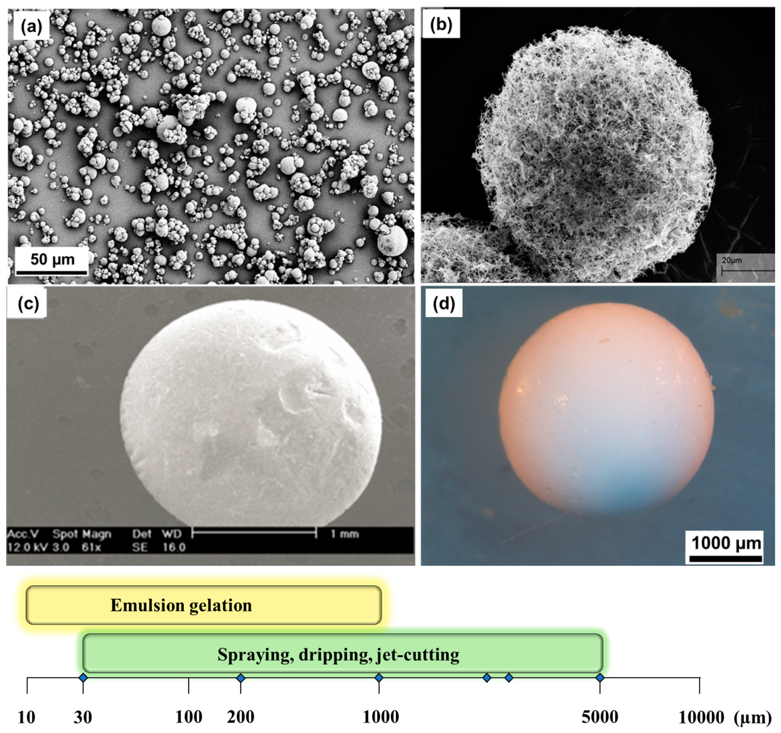
| Dropping | JetCutter | Spraying Atomization | Emulsion Gelation | |
|---|---|---|---|---|
| Particle size | 0.2–10 mm | 0.2–10 mm | 1–500 µm | 10–500 µm |
| Scale of the process (productivity) | 1 g/min (10 nozzle system) a | Technical scale (several kg/h) | Productivity depends on the nozzle | Technical scale possible |
| Needs of additives | No | No | No | Surfactants and oil |
| Advantages | Very simple | Versatile systems, simple, commercially available apparatus; monodispersed particles | Different sizes possible depending on the nozzle | Simple apparatus Particle size can be regulated by stirring and surfactants |
| Limitations | Limited productivity | Not suitable to produce small particles (<200 µm); limited processing window in terms of the rheological properties of solutions | Clogging, polydispersed particles | Washing from oil; Polydispersed particles |
© 2018 by the authors. Licensee MDPI, Basel, Switzerland. This article is an open access article distributed under the terms and conditions of the Creative Commons Attribution (CC BY) license (http://creativecommons.org/licenses/by/4.0/).
Share and Cite
Ganesan, K.; Budtova, T.; Ratke, L.; Gurikov, P.; Baudron, V.; Preibisch, I.; Niemeyer, P.; Smirnova, I.; Milow, B. Review on the Production of Polysaccharide Aerogel Particles. Materials 2018, 11, 2144. https://doi.org/10.3390/ma11112144
Ganesan K, Budtova T, Ratke L, Gurikov P, Baudron V, Preibisch I, Niemeyer P, Smirnova I, Milow B. Review on the Production of Polysaccharide Aerogel Particles. Materials. 2018; 11(11):2144. https://doi.org/10.3390/ma11112144
Chicago/Turabian StyleGanesan, Kathirvel, Tatiana Budtova, Lorenz Ratke, Pavel Gurikov, Victor Baudron, Imke Preibisch, Philipp Niemeyer, Irina Smirnova, and Barbara Milow. 2018. "Review on the Production of Polysaccharide Aerogel Particles" Materials 11, no. 11: 2144. https://doi.org/10.3390/ma11112144