Article

Construction of Microclimatic Zone Based on Convection–Radiation System for Local Cooling in Deep Mines

Faculty of Land Resources Engineering, Kunming University of Science and Technology, Kunming 650093, China
*
Author to whom correspondence should be addressed.
Energies 2025, 18(12), 3029; https://doi.org/10.3390/en18123029
Submission received: 23 May 2025 / Revised: 2 June 2025 / Accepted: 5 June 2025 / Published: 7 June 2025

Abstract

As global mineral resources at shallow depths continue to deplete, thermal hazards have emerged as a critical challenge in deep mining operations. Conventional localized cooling systems suffer from a fundamental inefficiency where their cooling capacity is rapidly dissipated by the main ventilation airstream. This study introduces the innovative concept of a “microclimatic circulation zone” implemented through a convection–radiation cooling system. The design incorporates a synergistic arrangement of dual fans and flow-guiding baffles that creates a semi-enclosed air circulation field surrounding the modular convection–radiation cooling apparatus, effectively preventing cooling capacity loss to the primary ventilation flow. The research develops comprehensive theoretical models characterizing both internal and external heat transfer mechanisms of the modular convection–radiation cooling system. Using Fluent computational fluid dynamics software, we constructed an integrated heat–moisture–flow coupled numerical model that identified optimal operating parameters: refrigerant velocity of 0.2 m/s, inlet airflow velocity of 0.45 m/s, and outlet aperture height of 70 mm. Performance evaluation conducted at a mining operation in Yunnan Province utilized the Wet Bulb Globe Temperature (WBGT) index as the assessment criterion. Results demonstrate that the enhanced microclimatic circulation system exhibits superior cooling retention capabilities, with a 19.83% increase in refrigeration power and merely 3% cooling capacity dissipation at a 7 m distance, compared to 19.23% in the conventional system. Thermal field analysis confirms that the improved configuration successfully establishes a stable microclimatic circulation zone with significantly more concentrated low-temperature regions. This effectively addresses the principal limitation of conventional systems where conditioned air is readily dispersed by the main ventilation current. The approach presented offers a novel technological pathway for localized thermal environment management in deep mining operations affected by heat stress conditions.

1. Introduction

With the progressive depletion of easily accessible shallow mineral resources globally, the mining industry has increasingly turned toward deep and ultra-deep extraction operations [1]. By 1996, over 80 mines worldwide had already reached exploitation depths exceeding 1000 m [2]. In these environments, high-temperature thermal hazards have emerged as a critical challenge, simultaneously compromising equipment durability and occupational health while substantially increasing operational costs [3,4].
Significant research efforts have addressed thermal management in deep mining environments. Krawczyk et al. [5] developed advanced hot-wire anemometric measurement systems that provide high-precision three-dimensional velocity field measurements essential for evaluating and optimizing these thermal management strategies. Xu et al. utilized computational modeling to evaluate various geothermal well configurations for their cooling and heat recovery performance [6], establishing technical frameworks for geothermal resource utilization in deep mining operations. Liu et al. [7] developed an integrated solution combining backfilling strategies, thermal hazard control, and geothermal extraction, incorporating phase change materials within mined-out areas alongside buried heat extraction systems, effectively offsetting both thermal management and backfilling expenses. In the domain of heat transfer mechanisms, Xin et al. [8] conducted comprehensive analyses of thermal interactions between high-temperature rock formations and ventilation airstreams, identifying critical parameters governing these heat exchange processes. Zhang et al. [9] extensively investigated gas–solid heat transfer principles as applied to localized cooling systems, establishing robust theoretical frameworks for cooling optimization. Wang et al. [10] examined thermal exchange dynamics in high-temperature roadways incorporating insulation layers and modeled temperature field evolution patterns, providing valuable insights for insulation system design in mining tunnels. Despite these advances in heat source characterization, insulation technology, geothermal utilization, and subterranean thermal environment control [11], increasing mining depths continue to present substantial challenges for whole-mine cooling approaches, including excessive refrigeration equipment loads and prohibitive energy demands [12]. Consequently, localized cooling strategies targeting specific operational zones have gained prominence as a preferred technological approach for thermal hazard mitigation in deep mines, offering advantages of reduced capital investment, rapid implementation, and enhanced energy efficiency.
In the application of localized cooling technologies, Li et al. [13] engineered and deployed specialized refrigeration systems to address elevated temperature and humidity conditions in transport roadway shift-change sections, demonstrating effective thermal management solutions for specific operational areas. Miao et al. [14] methodically investigated optimal configuration parameters for mine air cooling units to maximize cold air distribution efficiency. Regarding system optimization, You et al. [15] analyzed the relationship between valve aperture settings, pump rotation velocities, and chilled water network response characteristics. Hong et al. [16] introduced an integrated optimization methodology for pump performance curves and hydraulic network characteristics, substantially enhancing chilled water system operational efficiency. Gao et al. [17] improved system reliability through sophisticated valve-network topological modeling, while Zhou et al. [18] achieved significant energy consumption reductions through dynamic regulation of circulation pump frequencies and control valve positions. Experimental investigations by Rathod et al. [19] and Jannesari et al. [20] confirmed the substantial heat transfer enhancements achieved through fin structures and annular conduit configurations. Comprehensive economic and performance assessments of ice slurry cooling technologies and mobile phase-change thermal units [21,22] have established viable pathways for energy-efficient implementation of localized cooling systems.
The current body of research has made considerable strides in deep mine thermal hazard prevention, encompassing comprehensive analysis of heat sources, advanced insulation materials, integrated geothermal resource utilization, fundamental heat transfer mechanisms, and optimized localized cooling technologies. However, practical implementations frequently encounter challenges related to cooling capacity dissipation, resulting in suboptimal thermal energy utilization and restricted effective cooling zones. Therefore, the development of high-efficiency, modular cooling systems capable of adapting to complex mining environments while effectively maintaining cooling capacity and ensuring precise thermal delivery represents both significant theoretical advancement and practical innovation for enhancing thermal hazard management and ensuring occupational safety and comfort in deep mining operations.

2. Design Principles of Enhanced Fan Configuration for Modular Convection–Radiation Cooling System

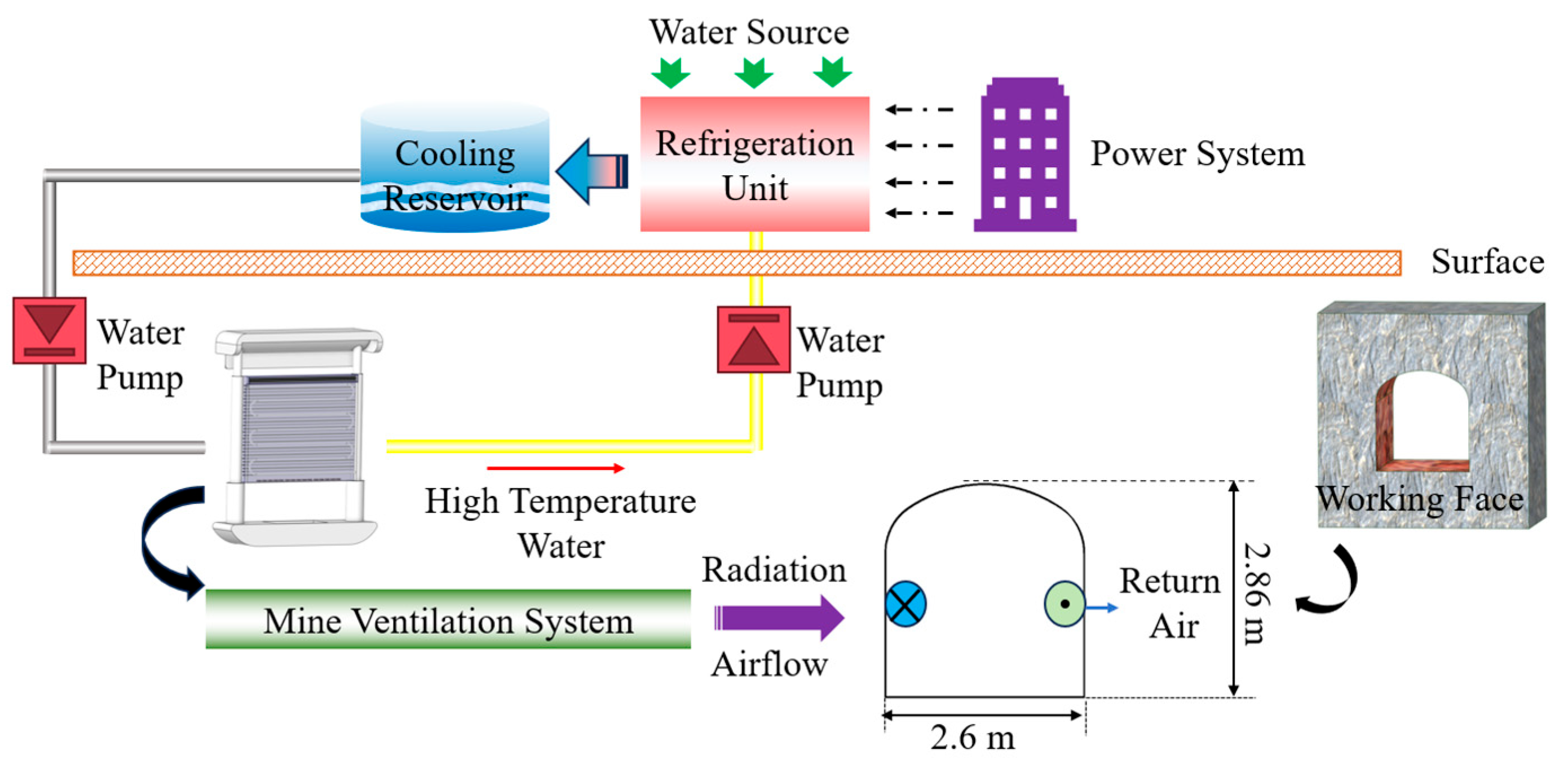
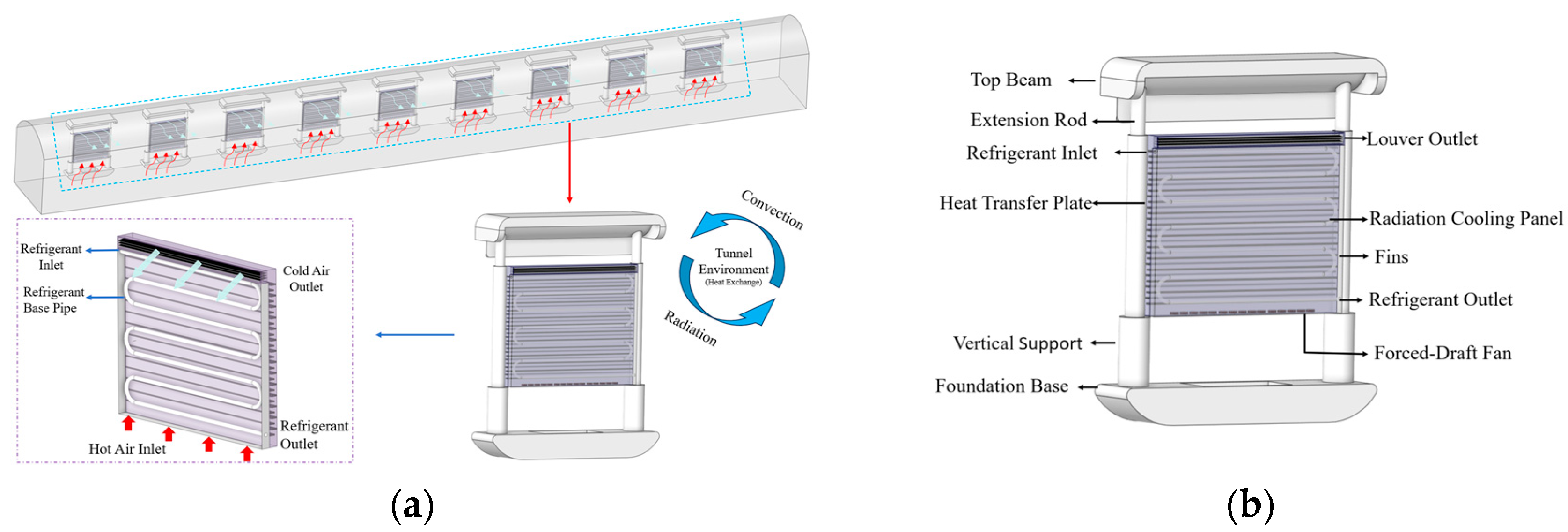
2.1. Modular Convection–Radiation Cooling System

As illustrated in Figure 1, this system utilizes centralized refrigeration provided by surface cooling stations or underground refrigeration nodes as the primary thermal sink. The refrigerant is hydraulically conveyed to various modular cooling units positioned at the working face, establishing the fundamental infrastructure for mine thermal environment management.
As shown in Figure 2a, the modular convection–radiation cooling system is specifically engineered for temperature regulation along the lateral walls of deep mine extraction roadways, integrating installation versatility and thermal management capabilities into a unified apparatus, making it highly advantageous for localized thermal environment control. Figure 2b presents a detailed representation of the structural configuration of the modular convection–radiation cooling system, which primarily comprises an engineered polymer enclosure (including upper beam, foundation base, vertical supports, and extension mechanisms), a refrigerant circulation network, and thermal exchange components. The engineered polymer enclosure provides structural integrity and vertical adjustability, enabling the apparatus to accommodate varying roadway geometries. The refrigerant circulation network employs 30 mm diameter seamless copper conduits arranged in a serpentine pattern, with copper metallic foam (porosity factor 2.3%) integrated within the conduits to enhance thermal transfer surface area. The thermal exchange component incorporates a radiative cooling module (consisting of refrigerant conduits, metallic radiation panels, and thermal interface materials) and a convective cooling module (composed of a forced-induction ventilation unit, finned flow-directing structures, and adjustable louver discharge ports). During operational cycles, the forced-induction ventilation unit actively extracts heated air from the roadway environment, directing it across internal cooled surfaces for comprehensive thermal exchange, subsequently distributing the conditioned air into the roadway space through the adjustable discharge ports. This integrated system not only effectively optimizes the localized thermal environment but also maximizes energy efficiency while maintaining cooling performance, establishing ergonomically appropriate working conditions for personnel in deep mining operations.

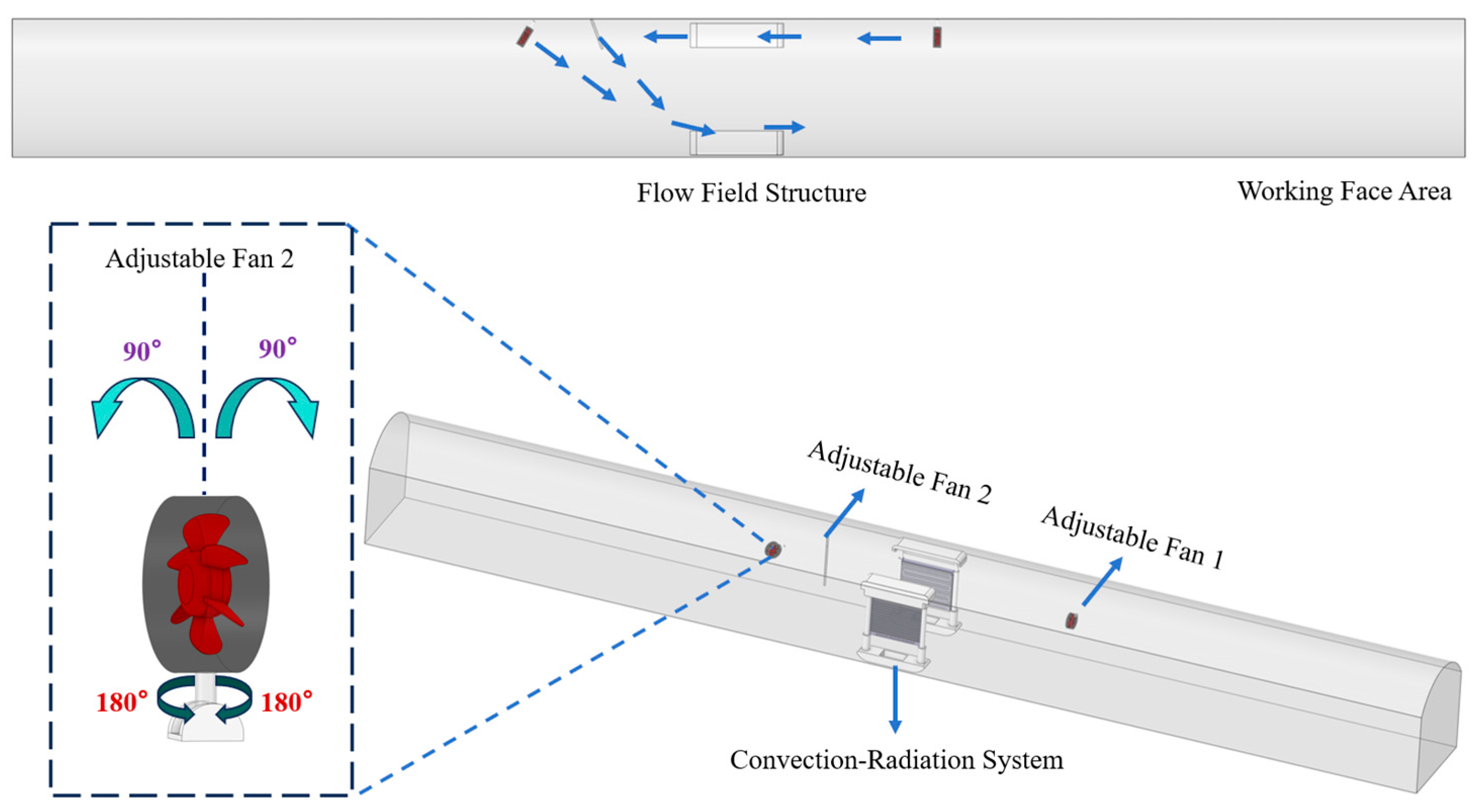
2.2. External Enhancement Design Concept and Configuration Scheme

Based on practical application of the convection–radiation cooling system in a deep metal mine in Yunnan Province, it was discovered that the main ventilation airflow caused significant scouring of the cold air produced by the system, resulting in substantial cooling capacity losses. Addressing this issue, Figure 3 illustrates the enhanced design concept and configuration scheme for the modular convection–radiation cooling system. Through collaborative design of external auxiliary fans and flow-guiding baffles, a relatively enclosed “microclimatic circulation zone” is established by positioning flow-guiding baffles and auxiliary fans behind the lateral side of the radiation cooling panel. This design functionality is primarily manifested in three aspects: firstly, the flow-guiding baffles precisely direct airflow pathways, enabling cold air to flow along predetermined trajectories, thereby reducing scouring loss effects; secondly, the synergistic action of dual fans generates a cold air circulation field, effectively preventing cooling capacity diffusion toward the main ventilation flow; thirdly, forced convection significantly enhances the heat exchange efficiency of the radiation cooling panel. The three-dimensional tunnel schematic in the figure intuitively demonstrates the installation position of this system in actual mine environments and the organizational pattern of cold airflow, illustrating how local thermal environments can be precisely controlled in complex tunnel settings. This enhancement design, based on fluid dynamics principles, significantly improves the system’s cooling capacity utilization efficiency, providing a reliable technical approach for heat hazard prevention in deep mining operations.

2.3. Theoretical Model Development

Based on energy conservation analysis, the modular convection–radiation cooling system can be divided into internal and external heat transfer components, with the heat transfer processes illustrated in Figure 4a,b.
To simplify the model and facilitate solution, the following assumptions are made:
(1)
Heat transfer processes are based on steady-state conditions.
(2)
The thickness of the radiation cooling panel is significantly smaller than its width; therefore, heat transfer along the thickness direction of the cooling radiation panel is negligible.
(3)
The influence of the semicircular tubing at the ends of the serpentine coil is disregarded.
The internal heat transfer process primarily encompasses heat transfer of the refrigerant water within the tubes, heat conduction through the tube walls, and heat transfer through the fins. The internal heat transfer process relationships are expressed as follows:
Q i n = Q c w = Q p i p e = Q r a d + Q f i n
Q c w = m ˙ w c p   Δ T w
Q p i p e = π d i L h c T w T p
Q r a d = T o T i 1 2 π λ 1 l n d o d i + T i T ¯ δ 2 λ 2
Q f i n = η f w d o + d o h l θ c
where Q i n represents the cooling capacity input to the system, Q c w denotes the heat transferred by the refrigerant water, Q p i p e indicates the heat transferred through the pipe walls, Q r a d describes the heat transferred through the radiation panel, and Q f i n refers to the heat transferred through the fins.
m ˙ w is the mass flow rate of refrigerant water (kg/s), c p denotes the specific heat capacity of water (kJ/(kg·K)), and Δ T w represents the temperature variation of refrigerant. (K) d i is the pipe external diameter (m), L is the pipe length (m), h c is the convective heat transfer coefficient inside the pipe (W/(m2·K)), T w is the average temperature of refrigerant water (K), and T p is the inner wall temperature of the pipe (K). T o is the outside wall temperature of the casing (K), T ¯ is the average temperature of the radiation cooling plate surface(K), λ 1 denotes the thermal conductivity of pipe wall material (W/(m2·K)), and λ 2 refers to the thermal conductivity of the radiation panel material (W/(m2·K)). d o and d i are the internal and external diameters of the pipe (m), δ 2 is the thickness of the radiation panel (m), η f represents the fin efficiency, w is the fin center distance, h l is the convective heat transfer coefficient of the fin surface to air, and θ c is the excess temperature of the fin (K).
The external heat transfer process is based on empirical formulas. The radiative heat exchange characteristics of the radiation panel [23] and heat transfer under natural convection conditions [24] provide the theoretical foundation for the external heat transfer analysis:
Q o u t = Q r a d , e n v + Q c o n v , r a d + Q c o n v , l o u v e r
Q r a d , e n v = σ ε T s 4 T w a l l 4
Q c o n v , r a d = 2.13 T a T s 1.31
Q c o n v , l o u v e r = h f A f T f T a
where Q r a d , e n v represents the radiative heat exchange between the radiation panel and the environment (W), Q c o n v , r a d is the convective heat transfer at the radiation panel surface (W) (based on natural convection conditions), Q c o n v , l o u v e r refers to the convective heat transfer at the louver outlet (W). σ is the Stefan–Boltzmann constant, 5.67 × 10⁻⁸ W/(m2·K4); ε is the surface emissivity (dimensionless); T w a l l denotes the tunnel wall temperature (K); T a represents the average air temperature inside the tunnel (K); T s is the average surface temperature of the radiation cooling panel (K), h f is the convective heat transfer coefficient of air in the tunnel, W/(m2·K); A f refers to the louver outlet area (m2); and T f is the average outlet air temperature (K).
Through mathematical rearrangement, the expressions for the system outlet temperature T f and the average radiation panel temperature T s , as shown in Figure 4c, can be derived as
T s = δ 2 λ 2 2 π λ 1 T o T i + l n d o d i η f w d o + d o h l θ c l n d o d i Q i n
T f = Q 2.13 T a T s 1.31 σ ε T s 4 T w a l l 4 h f A f + T a
To achieve optimal arrangement and efficient design of the enhanced structural system, the airflow vector decomposition is expressed as
v i x = v i c o s α i
v i y = v i s i n α i
where v i x and v i y represent the velocity components along the x-axis and y-axis, respectively (m/s); v i denotes the magnitude of velocity for the i-th fan (m/s); and α i is the outlet angle of the i-th fan (°).
The reflection theorem is used to estimate the direction of airflow after deflection by the baffle:
α out = 180 2 θ
where α out is the outlet angle after reflection (°), and θ is the angle between the baffle and the side wall (°).
The dynamic pressure loss in the local fan system is calculated as
Δ p = ζ × ρ v 2 2
where Δ p represents the local pressure loss (Pa); ζ is the local resistance coefficient for airflow passing through the baffle; ρ is the air density (kg/m3); and v is the air velocity (m/s).
Considering the velocity effect on reflection, the formula is given by
t a n β = t a n α e
where α is the incident angle of airflow (°); β is the exit angle of airflow (°); and e is the direction recovery coefficient, dimensionless.
The final resultant velocity magnitude in vector form is expressed as
V = i = 1 n v i = i = 1 n v i c o s α i i ^ + i = 1 n v i s i n α i j ^
where V is the system’s resultant velocity, v i represents the velocity vector of the i - t h fan, and i ^ and j ^ denote the unit vectors in the x and y directions, respectively.
The specific calculation methods for velocity magnitude and direction angle are
β = a r c t a n V y V x
V = V x 2 + V y 2
where β is the direction angle of the resultant airflow (°), and V is the magnitude of the resultant airflow velocity (m/s).

2.4. System Safety and Compliance Assessment

Given the unique characteristics of deep mine production environments and the paramount principle of operational safety, this research conducted a systematic safety and compliance assessment of the external enhancement design for the modular convection–radiation cooling system based on national mine safety regulations and ventilation technical standards. According to the relevant provisions in the “Safety Regulations for Metal and Non-metal Mines” (GB 16423-2020) [25] and the “Mine Ventilation Safety Specifications” (AQ 1028-2006) [26], the dual fan-flow guiding baffle collaborative system proposed in this study falls within the category of “localized cooling technology” rather than “integrated air circulation system”, with its airflow organization characteristics meeting regulatory requirements.
The circulating airflow formed by the system occupies only 15.6–19.8% of the tunnel cross-section and establishes clear flow field partitioning with the main ventilation current, preventing short-circuiting or disruption of primary ventilation airflow. This structural design complies with the stipulation in the “Safety Regulations for Metal and Non-metal Mines” stating that “local ventilation devices should not affect the normal operation of the mine’s main ventilation system”.
Special consideration must be given to the concentration control requirements for hazardous gases and dust in the mining operational environment. As shown in Table 1, the limit values are derived from the “Safety Regulations for Metal and Non-metal Mines”. When dust concentrations in the workplace exceed the specified permissible limits, the system must immediately implement safety protection measures. To ensure compliance with mining safety regulations, this study designed an automatic control logic based on sensor linkage mechanisms; when dust concentration sensors detect that dust or hazardous gas concentrations in the working face exceed standards, the system immediately triggers safety protection procedures, shutting down the circulation air system and increasing the power of local forced-air and exhaust fans to enhance ventilation dilution effects, ensuring that personnel are not exposed to harmful environments exceeding standard thresholds. This linkage control mechanism achieves real-time monitoring and rapid response through a programmable logic controller (PLC), with a response time not exceeding 5 s, prioritizing ventilation safety and personnel health under abnormal operating conditions.

3. System Performance Theoretical Model and Numerical Simulation

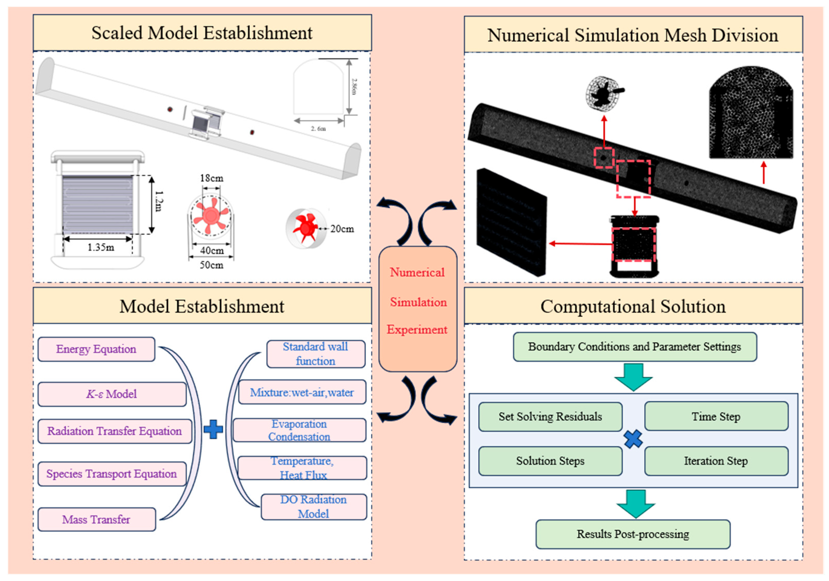
3.1. Research Approach and Numerical Simulation Workflow

This study constructs a heat–moisture coupled multi-physics numerical model based on the modular convection–radiation cooling system. A comparison between simulation results and measured data at a 1404 m working face in Yunnan Province without cooling equipment installation (Figure 5) shows that the maximum error is only 2.1% when no cooling measures are implemented, accurately reflecting the thermal environment characteristics of the intake airway (0–680 m) and return airway (680–1200 m), thereby validating the model’s predictive accuracy in complex mine ventilation systems.
Taking refrigerant velocity, inlet air velocity, and outlet height as key influencing factors, extensive numerical simulation work was systematically conducted. The numerical simulation workflow (Figure 6) encompasses multiple stages, including geometric simplification, unstructured mesh generation, boundary condition setup, SIMPLE algorithm solution, and monitoring verification.
The detailed parameter settings for the multi-physics coupled simulation are presented in Table 2, which specifies the solver configuration, turbulence modeling approach, boundary conditions, and discretization schemes employed in the Ansys Fluent 2023 R2 computational framework. These parameters were carefully selected to ensure accurate representation of the complex heat–moisture–flow interactions within the mine tunnel environment.
Following application to actual working conditions at the Yunnan lead–zinc mine, it was identified that airflow-induced cooling capacity loss represents the critical factor affecting system efficiency. To address this issue, an innovative design incorporating external dual-fan and flow-guiding baffle collaboration was proposed to establish localized circulation fields for controlling cooling capacity diffusion. The system performance was quantitatively evaluated using WBGT indices and thermal comfort standards, providing a reliable engineering solution for precision cooling in deep mines.

3.2. Governing Equations and Model Parameters

To construct a numerical model that accurately reflects the coupled heat–moisture–flow environment in mine tunnels, this study establishes the following fundamental assumptions based on the principles of fluid mechanics and heat transfer:
  • Airflow in the mine environment is considered as incompressible flow.
  • The chilled water flow rate, temperature, and inlet airflow remain constant and uniform.
  • The contact thermal resistance between the packing material and heat exchange tubes is neglected.
The thermophysical properties of materials used in the multi-physics coupled model are summarized in Table 3. Based on these assumptions, the standard k-ε turbulence model is employed to describe the flow and heat transfer characteristics of the system. This model effectively captures the turbulent characteristics of complex flow fields in mines by solving the Reynolds-averaged Navier–Stokes (RANS) equations combined with transport equations for turbulent kinetic energy (k) and turbulent dissipation rate (ε). Considering the water vapor evaporation and condensation phenomena existing in the tunnel environment, this model further integrates species transport equations to construct a comprehensive multi-physics coupled numerical model. The core governing equations are formulated as follows [27,28,29,30]:
ρ t + x i ρ u i = S mass
t ρ u i + x j ρ u i u j = p x i + τ i j x j + ρ g i + F i
t ρ H + x i ρ u i H = x i k eff T x i j H j J j , i + u j τ i j + S H
t ρ ψ w + x i ρ u i ψ w = x i ρ D w ψ w x i + μ t P r t ψ w x i + θ T 1 T T x i + S w
where ρ is the fluid density (kg/m3); x i , x j are the spatial coordinate components (m); u i , u j are the velocity components (m/s); S mass is the mass source term (kg/m3·s); τ i j is the stress tensor component (Pa); g i is the gravitational acceleration component (m/s2); F i is the external body force component (N/m3); H is the total specific enthalpy (J/kg); k eff is the effective thermal conductivity (W/m·K); H j is the species specific enthalpy (J/kg); J j , i is the species diffusive flux component (kg/m2·s); S H is the energy source term (W/m3); ψ w is the water vapor mass fraction (dimensionless); D w is the diffusion coefficient of water vapor in air (m2/s); μ t is the turbulent dynamic viscosity (Pa·s); P r t is the turbulent Prandtl number (dimensionless); θ T is the thermal diffusion coefficient (kg/m·s·K); and S w is the water vapor source term (kg/m3·s).

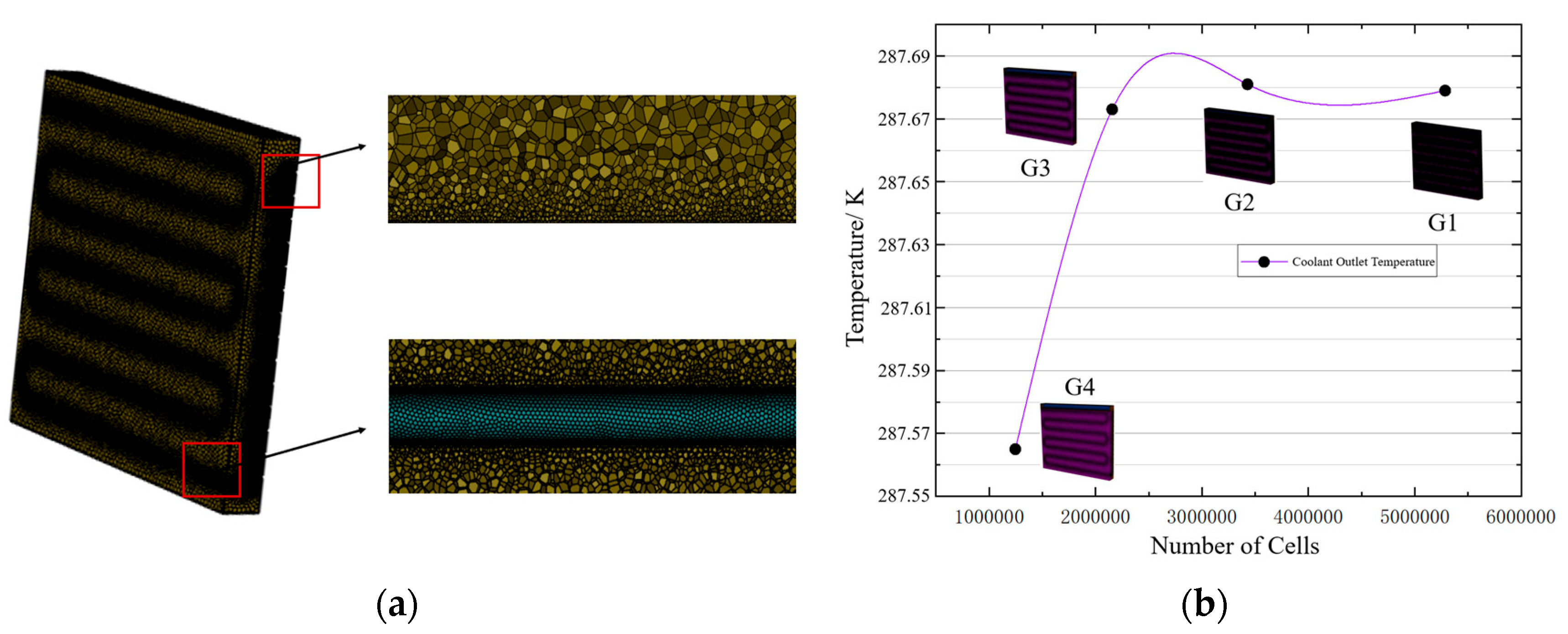
3.3. Grid Independence Verification

To ensure the accuracy of numerical simulation results, this study conducted grid independence verification for the computational domain of the modular convection–radiation cooling system. The airflow in the tunnel exhibits turbulent flow characteristics, and the standard k-ε equations combined with standard wall functions were employed for calculations, requiring the dimensionless wall distance y+ to be maintained within the range of 30–60. Based on different mesh sizes, four grid schemes were designed for this study, with the number of grid cells arranged from least to most, designated as schemes G1, G2, G3, and G4. The specific design and grid quantities for each mesh scheme are presented in Table 4. The y+ values throughout the entire computational domain comply with the requirements, and the number of isolated cells in each grid scheme falls within acceptable ranges, ensuring that all mesh qualities meet simulation requirements.
To validate the rationality of the mesh division and wall function selection, considering that the chilled water serves as the most critical cooling medium in the modular convection–radiation cooling system, the outlet water temperature of the coolant was selected as the indicator for grid independence verification. Simulation calculations were performed for different grid schemes, and the results demonstrated that when the grid number reached the G3 scheme (3.549 million cells), as shown in Figure 7, further increases in grid density had an impact of less than 0.5% on the computational results. Taking into account both computational accuracy and efficiency, the G3 scheme was selected as the mesh configuration for all subsequent numerical simulations.

4. System Cooling Performance and Energy Consumption Analysis

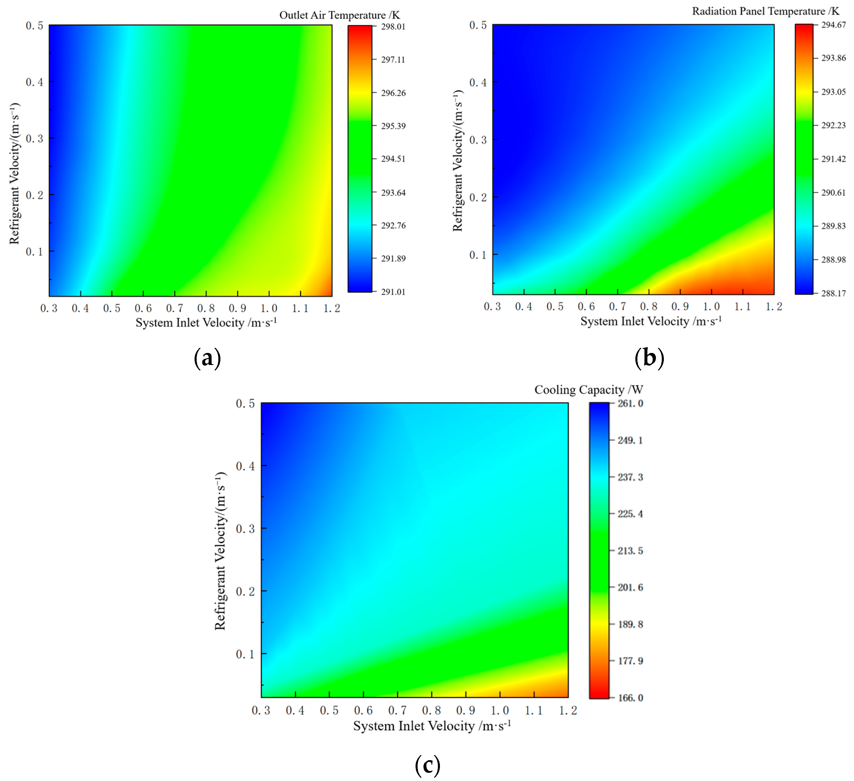
4.1. System Cooling Capacity and Determination of Optimal Operating Condition

To investigate the influence patterns of key operating parameters on system performance, this study analyzed the effects of refrigerant velocity (0.02–0.5 m/s) and inlet air velocity (0.3–1.2 m/s) on louver outlet air temperature, radiation panel temperature, and system cooling capacity under fixed outlet height conditions. The results are presented in Figure 8a–c. The increase in inlet air velocity exhibited a negative impact on cooling performance. This occurs because high-velocity inlet air introduces greater thermal enthalpy, leading to an elevated total enthalpy of the incoming airflow. Although the intensified turbulence within the interlayer enhances the heat exchange process, under limited cooling capacity supply, this inevitably results in increased outlet air temperature and reduced net cooling capacity.
The color distribution in the contour plots clearly demonstrates that the cooling capacity in low-inlet-velocity regions is significantly higher than that in high-velocity regions. Based on comprehensive analysis of the contour plots and power configuration results, the system achieves optimal comprehensive performance under the parameter combination of refrigerant velocity ranging from 0.2 to 0.3 m/s and inlet air velocity ranging from 0.4 to 0.5 m/s.

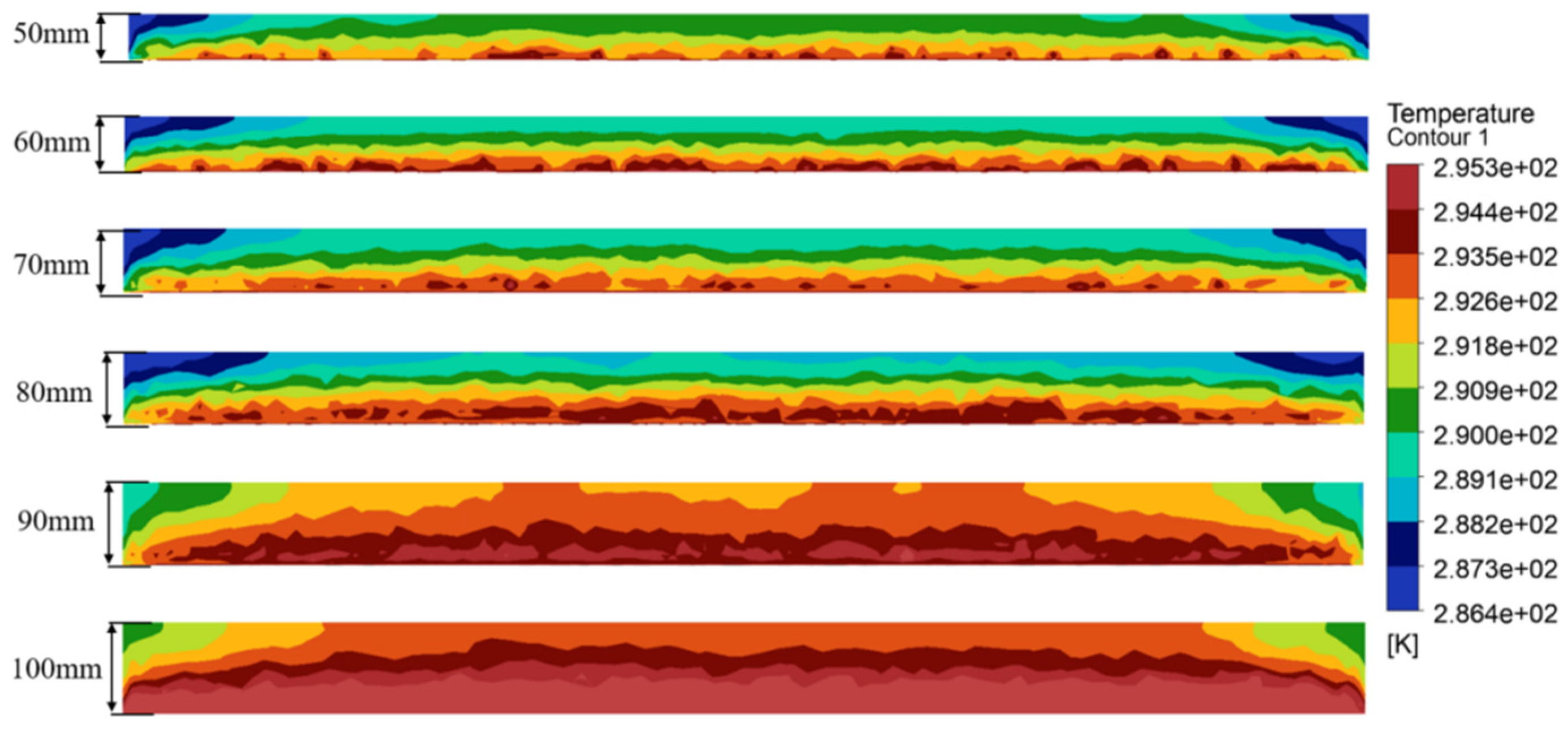
4.2. Impact of Outlet Height on System Cooling Capacity

Based on Figure 9a–c, the influence of outlet height on system performance exhibits distinct threshold effect characteristics, which primarily involves the trade-off between pressure balance and heat exchange efficiency in fluid dynamics. As the outlet height increases from 50 mm to 100 mm, significant changes occur in the internal pressure distribution of the system. Under the forced-draft design with fixed inlet conditions, the outlet height directly affects the internal pressure gradient and flow characteristics of the system.
As illustrated in Figure 10, when the outlet height reaches 70 mm, the system achieves a critical equilibrium point. At this configuration, the system maintains an appropriate pressure level that ensures adequate contact between cold air and heated surfaces for heat exchange, while avoiding excessive resistance and energy consumption associated with undersized outlets. Although smaller outlets (50–60 mm) provide enhanced convective heat transfer effects, they result in substantial system pressure losses. Conversely, outlets larger than 80 mm lead to excessively low system pressure, where despite increased flow rates, heat exchange efficiency decreases and cooling capacity tends to stabilize without significant further improvement.
After comprehensive consideration, 70 mm was ultimately selected as the optimal outlet height, representing an optimization result based on integrated evaluation of heat exchange efficiency, energy utilization rate, and practical engineering feasibility. Under this height configuration, the system achieves optimal heat transfer performance and energy consumption balance when operating with a refrigerant velocity of 0.2 m/s and inlet air velocity of 0.45 m/s, fully meeting the practical application requirements of deep mine operations with a cooling power of 261 W. This demonstrates the design principle that precise adjustment of outlet geometric parameters can significantly optimize overall heat exchange performance.

4.3. Cooling Effect Analysis of Deep Mine Excavation Working Face

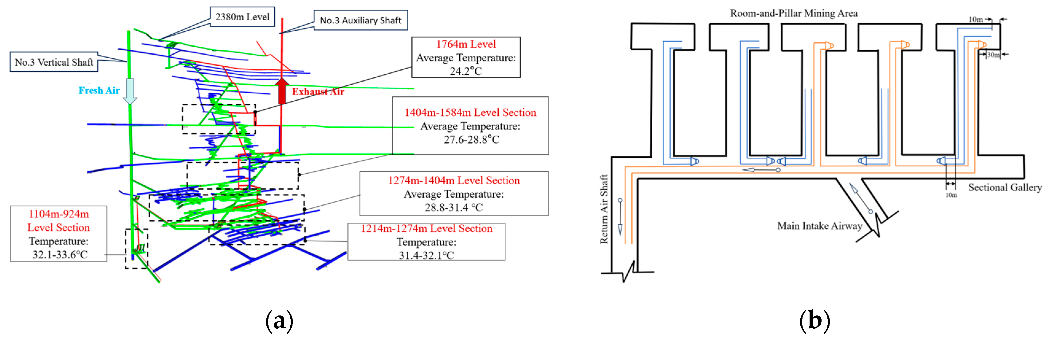
4.3.1. Research Background and Engineering Overview

This study focuses on the excavation working face at a 1404 m level in a ultra-deep mine in Yunnan Province, located at an excavation depth of 976 m. The underground ventilation system of the 1404 m working face is illustrated in Figure 11a. The tunnel cross-section has an arched profile with a width of 2.6 m and height of 2.86 m. This mining area employs a combined local ventilation system. As shown in the schematic diagram of tunnel layout and ventilation system for this area, fresh air is delivered from the main intake airway through sectional galleries (air velocity approximately 3.5 m/s) via forced-draft fans into the room-and-pillar mining area, as depicted in Figure 11b. The air velocity within the excavation tunnel ranges from 0.2 to 1 m/s, while exhaust air is removed through exhaust fans from the return air shaft to the surface. The working face temperature is 31.7 °C with a relative humidity of 60%, and the tunnel wall temperature is 32.9 °C.

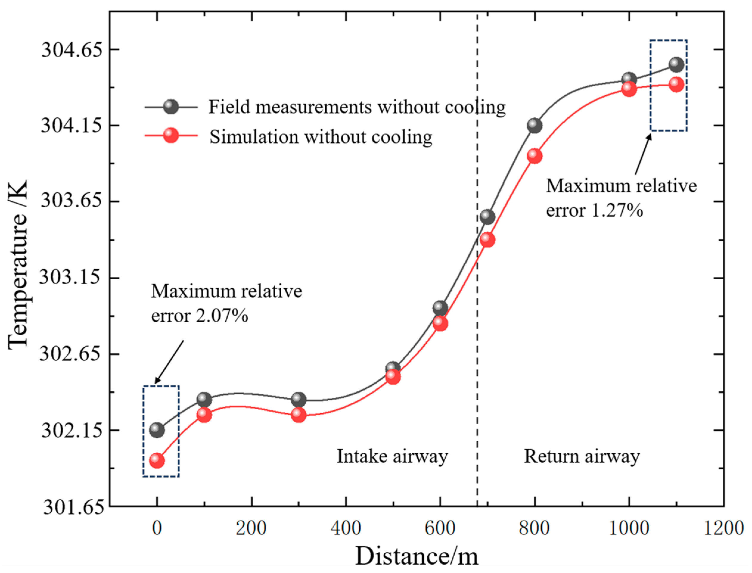
4.3.2. System Cooling Effect and Energy Loss Analysis

To quantitatively evaluate the cooling effectiveness of the modular convection–radiation cooling system, this study adopts the Wet Bulb Globe Temperature (WBGT) index as the thermal environment assessment criterion. Based on the physiological adaptation characteristics and thermal tolerance capacity differences among miners, the research establishes three evaluation parameters, adapted worker comfort zone ratio ( ϕ a d a p t ), non-adapted worker comfort zone ratio ( ϕ n o n - a d a p t ), and extreme thermal tolerance comfort zone ratio ( ϕ l i m i t ), corresponding to work area proportions with WBGT < 301.15 K, WBGT < 299.15 K, and WBGT < 302.00 K, respectively.
W B G T = 0.7 T w b + 0.3 c
where T w b is the wet bulb temperature (K); c is the globe temperature (K).
ϕ a d a p t = D 1 Z × 100 % W B G T < 301.15   K
ϕ n o n - a d a p t = D 2 Z × 100 % W B G T < 299.15   K
ϕ l i m i t = D 3 Z × 100 % W B G T < 302.26   K
where ϕ a d a p t is the adapted worker comfort zone ratio; ϕ n o n - a d a p t is the non-adapted worker comfort zone ratio; ϕ l i m i t is the extreme thermal tolerance comfort zone ratio; D 1 , D 2 , D 3 are the distances satisfying different WBGT requirements (m); and Z is the total length of the working face (m).
The research results demonstrate that the full-line deployment of modular convection–radiation systems in excavation tunnels exhibits significant cooling effects under different installation configurations, with performance varying according to the radial distance from the working face. The vertical temperature distribution in the tunnel is illustrated in Figure 12 which shows that the system’s cooling effect in the tunnel radial direction exhibits stratified characteristics.
As shown in Table 5, at the 1404 m level working face, under the 25 m alternating bilateral installation configuration, the adapted worker comfort zone coverage ( ϕ a d a p t ) reaches 100%, the non-adapted worker comfort zone ( ϕ n o n - a d a p t ) achieves 75%, and the safe thermal tolerance limit zone ( ϕ l i m i t ) attains 100%, showing slight advantages compared to unilateral installation ( ϕ a d a p t = 100%, ϕ n o n - a d a p t = 72%). As mining depth increases, the system’s cooling efficiency gradually decreases. At the 924 m level, ϕ a d a p t drops to 60%, and ϕ n o n - a d a p t decreases to 25%, while ϕ l i m i t remains at 85%.
These results indicate that the system can provide favorable thermal environments for various types of workers at relatively shallow depths. However, with increasing depth, the comfort assurance capability for non-adapted workers shows the most significant decline, while the safe thermal tolerance limit coverage is relatively less affected. This confirms both the applicability and limitations of the system under deep mine conditions.

4.3.3. Fan-Enhanced System Comfort Improvement and Energy Consumption Analysis in Mine Tunnels

Although the aforementioned research provided detailed analysis of the cooling effects of full-line tunnel deployment, in actual mine production operations, only the working face and its adjacent areas require focused cooling, while other areas do not need to maintain equivalent comfort levels. This approach aligns more closely with the practical engineering concept of localized cooling. Based on this principle, this study focuses on the cooling performance of modular convection–radiation systems in localized deployment at working faces. This strategy not only satisfies the comfort requirements of operating personnel but also significantly reduces energy consumption costs.
Figure 13 presents a comparative demonstration of cooling capacity loss characteristics and temperature field distribution before and after system improvement. The improved system employs a dual-fan and flow-guiding baffle collaborative design, resulting in significantly enhanced cooling capacity retention efficiency. The design parameters of the guide plate inclination angle θ and fan spacing are determined based on CFD simulation analysis and fluid mechanics principles. The system operational configuration is designed as follows: airflow from Fan 1 first passes through radiation cooling panel 1 for cooling, with Fan 1 positioned at a distance greater than five times the fan diameter from the radiation panel to ensure adequate airflow development and effective heat exchange. The cooled air from radiation panel 1 then flows toward the guide plate, whose inclination angle θ is determined by comprehensively considering tunnel dimension constraints and Fan 2’s installation angle. Through fluid mechanics empirical formulas, the optimal flow direction is estimated to ensure that the resultant airflow from the guide plate and Fan 2 effectively passes through radiation cooling panel 2, forming a complete circulation cooling loop. CFD numerical simulation provides the basis for achieving optimal airflow organization and cooling performance through this parameter configuration. To accurately evaluate energy utilization efficiency and cooling capacity transfer characteristics, this study adopts the heat flux method for system analysis. The quantitative calculation relationships are as follows:
Q l o s s = ρ × V × A × c p × T a m b i e n t T s e c t i o n
η l o s s = Q l o s s Q c o o l i n g × 100 %
where T a m b i e n t is the ambient temperature (K); T s e c t i o n is the average temperature at the specified cross-section (K); A is the effective cross-sectional area (m2); η l o s s is the cooling loss percentage (%); Q c o o l i n g is the total system cooling power (W); and Q l o s s is the cooling loss (W).
As illustrated in Figure 14, the dual-fan and flow-guiding baffle collaborative design successfully achieves the construction of a “microclimatic circulation zone”. The improved system exhibits a cooling capacity loss rate of only 3% at distances exceeding 7 m, compared to 19.23% for the unimproved system. Simultaneously, this optimization design enhances the system’s refrigeration power by approximately 19.83%, demonstrating significant achievements in both energy utilization efficiency and cooling capacity retention.

5. Conclusions

Faced with the thermal hazard challenges in deep mine operations, existing refrigeration and cooling technologies often suffer from limitations such as high energy consumption and low efficiency. To address this problem, this research explores a novel microclimatic regulation method for tunnel environments based on modular convection–radiation systems. Through the integration of theoretical analysis and practical application, the following research achievements have been obtained:
(1)
The optimal operating parameters for the modular convection–radiation system were determined through numerical simulation: refrigerant velocity of 0.2 m/s, inlet air velocity of 0.45 m/s, and outlet height of 70 mm. Under this parameter combination, the system achieves optimal heat transfer performance and energy consumption balance, with a cooling power of 261 W.
(2)
WBGT index evaluation demonstrates that optimal performance is achieved when employing 25 m bilateral alternating installation at the 1404 m working face, with adapted personnel comfort coverage reaching 100%. As mining depth increases, system performance shows a declining trend. At the 924 m level, the adapted comfort zone decreases to 60%, while the safe thermal tolerance zone remains above 85%, indicating that this technology maintains application potential under various depth conditions.
(3)
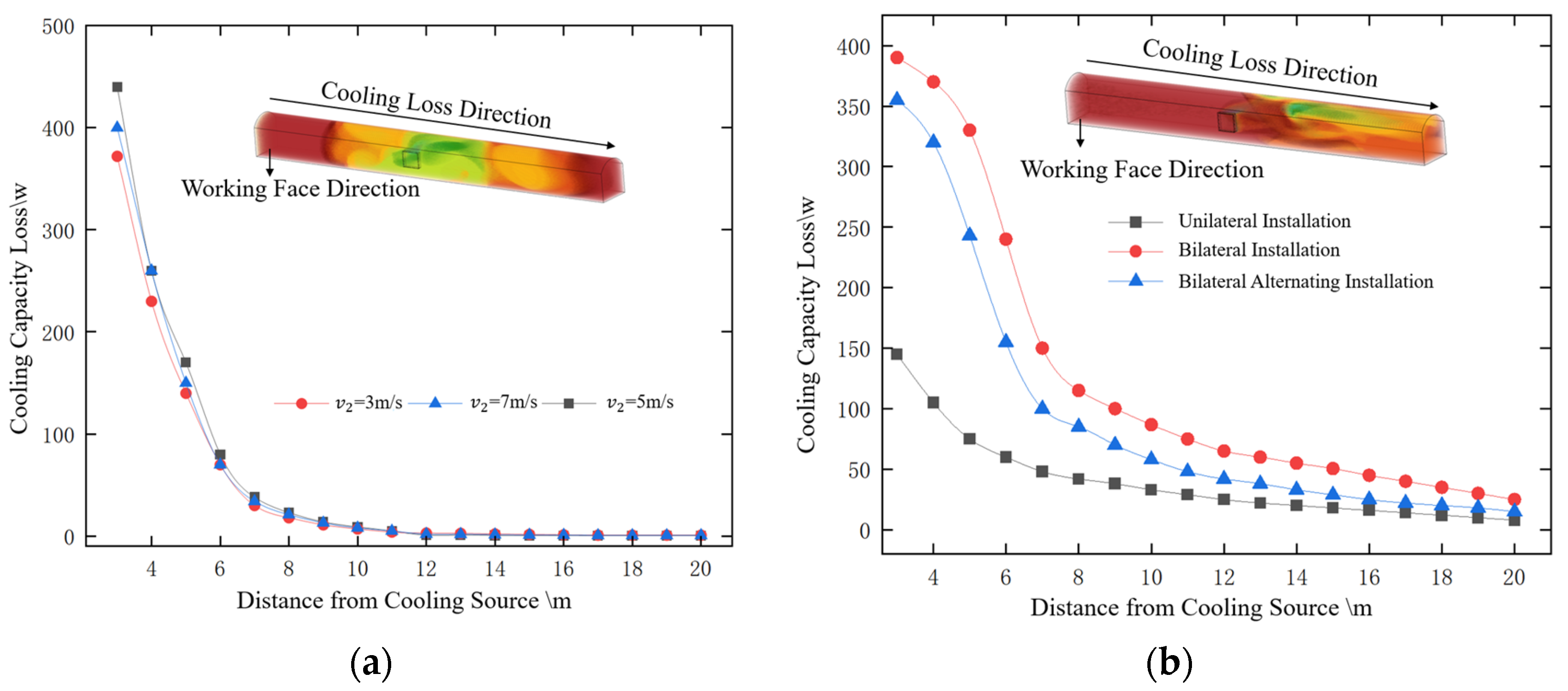
The dual-fan and flow-guiding baffle collaborative design successfully achieves the construction of a “microclimatic circulation zone”. The improved system exhibits a cooling capacity loss rate of only 3% at a 7 m distance, compared to 19.23% for the unimproved system, while simultaneously enhancing refrigeration power by approximately 19.83%.
(4)
Field application verification was conducted to analyze the compatibility of this system with the overall mine ventilation system. Results indicate that the system’s impact on the ventilation system is equivalent to a local obstruction, occupying only 15.6–19.8% of the tunnel cross-section. The main ventilation airflow normally divides after passing through the working face, flows to the sectional galleries, and finally converges into the return airways, maintaining a complete ventilation circuit. Airflow monitoring results from sectional galleries and main return airways show that system operation only reduces ventilation volume by 0.1–0.3%. Field verification demonstrates that system operation does not cause ventilation short-circuiting or airflow disturbance, ensuring the stability and safety of the mine ventilation system.
In conclusion, the microclimatic construction technology based on convection–radiation systems proposed in this study can effectively address cooling capacity loss issues, creating favorable thermal environment conditions for future adaptive optimization and intelligent control strategies to cope with mining operations under increasingly extreme conditions.

Author Contributions

Conceptualization, X.C.; methodology, X.C. and X.W.; software, X.C.; validation, X.C., H.W. and X.W.; formal analysis, X.C.; investigation, H.W.; resources, X.C.; data curation, X.C. and H.W.; writing—original draft preparation, X.C.; writing—review and editing, X.C. and X.W.; visualization, X.C.; supervision, X.W.; project administration, X.W.; funding acquisition, X.C. All authors have read and agreed to the published version of the manuscript.

Funding

This research received no external funding.

Data Availability Statement

The original contributions presented in the study are included in the article, further inquiries can be directed to the corresponding author.

Conflicts of Interest

The authors declare no conflict of interest.

Abbreviations

Heat Transfer Variables
SymbolDescriptionUnits
Q i n Cooling capacity input to the systemW
Q c w Heat transferred by the refrigerant waterW
Q p i p e Heat transferred through the pipe wallsW
Q r a d Heat transferred through the radiation panelW
Q f i n Heat transferred through the finsW
Q o u t External heat transferW
Q r a d , e n v Radiative heat exchange between radiation panel and environmentW
Q c o n v , r a d Convective heat transfer at radiation panel surfaceW
Q c o n v , l o u v e r Convective heat transfer at louver outletW
Q l o s s Cooling lossW
Q c o o l i n g Total system cooling powerW
Temperature Variables
SymbolDescriptionUnits
Δ T w Temperature variation of refrigerant waterK
T w Average temperature of refrigerant waterK
T p Inner wall temperature of the pipeK
T s Average surface temperature of radiation cooling panelK
T f Average outlet air temperatureK
T a Average air temperature inside the tunnelK
T w a l l the tunnel wall temperatureK
T w b Wet bulb temperatureK
T o Coil outer wall temperatureK
T i Coil inner wall temperatureK
T ¯ Average temperatureK
θ c Excess temperature of the finK
c Globe temperatureK
T a m b i e n t Ambient temperatureK
T s e c t i o n Average temperature at specified cross-sectionK
Flow and Velocity Variables
SymbolDescriptionUnits
m ˙ w Mass flow rate of refrigerant waterkg/s
v i Magnitude of velocity for the i-th fanm/s
v i x Velocity component along x-axism/s
v i y Velocity component along y-axism/s
V System’s resultant velocity vectorm/s
v i Velocity vector of the i-th fanm/s
V Magnitude of resultant airflow velocitym/s
V x Velocity component in x-directionm/s
V y Velocity component in y-directionm/s
u i , u j Velocity componentsm/s
Geometric Parameters
SymbolDescriptionUnits
d i Pipe internal diameterm
d o Pipe external diameterm
L Pipe lengthm
δ 2 Thickness of radiation panelm
w Fin center distancem
A f Louver outlet aream2
A Effective cross-sectional aream2
x i , x J Spatial coordinate componentsm
Angular Variables
SymbolDescriptionUnits
α i Outlet angle of the i-th fan°
α out Outlet angle after reflection°
α Incident angle of airflow°
β Exit angle of airflow; Direction angle of resultant airflow°
θ Angle between baffle and side wall°
Heat Transfer Coefficients
SymbolDescriptionUnits
h c Convective heat transfer coefficient inside pipeW/(m2·K)
h l Convective heat transfer coefficient of fin surface to airW/(m2·K)
h f Convective heat transfer coefficient of air in tunnelW/(m2·K)
k eff Effective thermal conductivityW/(m2·K)
Material Properties
SymbolDescriptionUnits
λ 1 Thermal conductivity of pipe wall materialW/(m·K)
λ 2 Thermal conductivity of radiation panel materialW/(m·K)
ρ Fluid density; Air densitykg/m3
c p Specific heat capacity of waterkJ/(kg·K)
μ t Turbulent dynamic viscosityPa·s
Efficiency and Performance Variables
SymbolDescriptionUnits
η f Fin efficiency
η l o s s Cooling loss percentage%
ε Surface emissivity
ζ Local resistance coefficient for airflow
e Direction recovery coefficient
Pressure Variables
SymbolDescriptionUnits
Δ p Local pressure lossPa
p PressurePa
Comfort Zone Variables
SymbolDescriptionUnits
W B G T Wet Bulb Globe Temperature°C
ϕ a d a p t Adapted worker comfort zone ratio%
ϕ n o n - a d a p t Non-adapted worker comfort zone ratio%
ϕ l i m i t Extreme thermal tolerance comfort zone ratio%
D 1 Distance satisfying WBGT < 28 °Cm
D 2 Distance satisfying WBGT < 26 °Cm
D 3 Distance satisfying WBGT < 29.11 °Cm
Z Total length of working facem
Fluid Mechanics Variables
SymbolDescriptionUnits
τ i j Stress tensor componentPa
g i Gravitational acceleration componentm/s2
F i External body force componentN/m3
H Total specific enthalpyJ/kg
H j Species specific enthalpyJ/kg
J j , i Species diffusive flux componentkg/(m2·s)
ψ w Water vapor mass fraction
D w Diffusion coefficient of water vapor in airm2/s
P r t Turbulent Prandtl number
θ T Thermal diffusion coefficientkg/(m·s·K)
Source Terms
SymbolDescriptionUnits
S mass Mass source termkg/(m3·s)
S H Energy source termW/m3
S w Water vapor source termkg/(m3·s)
Constants
SymbolDescriptionUnits
σ Stefan–Boltzmann constantW/(m2·K4)
i ^ , j ^ Unit vectors in x and y directions

References

  1. Cai, M.; Li, P.; Tan, W.; De Silva, R.V.; Wu, H.; Xu, S.; Feng, X. Key engineering technologies to achieve green, intelligent, and sustainable development of deep metal mines in China. Engineering 2021, 7, 1513–1517. [Google Scholar] [CrossRef]
  2. Ranjith, P.G.; Zhao, J.; Ju, M.; De Silva, R.V.K.; Rathnaweera, T.D.; Bandara, A.K.M.S. Opportunities and challenges in deep mining: A brief review. Engineering 2017, 3, 546–551. [Google Scholar] [CrossRef]
  3. Cai, M.; Ma, M.; Pan, J.; Gao, F.; Zhao, J.; Yu, S.; Wang, K.; Ding, W. Current status and prospects of co-exploitation models for mineral and geothermal resources. Chin. J. Eng. Sci. 2022, 44, 1669–1681. [Google Scholar]
  4. Aizawa, K.; Uyeshima, M.; Kitada, K.; Koyama, T.; Utsugi, M.; Hase, H.; Hashimoto, T.; Inoue, H.; Suzuki, A.; Koike, K.; et al. Magmatic fluid pathways in the upper crust: Insights from dense magnetotelluric observations around the Kuju volcanoes, Japan. Geophys. J. Int. 2022, 228, 755–772. [Google Scholar] [CrossRef]
  5. Krawczyk, J.; Ligęza, P.; Poleszczyk, E.; Skotniczny, P. Advanced hot-wire anemometric measurement systems in investigation of the air flow velocity fields in mine headings. Arch. Min. Sci. 2011, 56, 683–699. [Google Scholar]
  6. Xu, Y.; Li, Z.; Chen, Y.; Wu, Z.; Yang, G.; Feng, L.; Kong, Z.; Jiang, Q.; Liu, J. Synergetic mining of geothermal energy in deep mines: An innovative method for heat hazard control. Appl. Therm. Eng. 2022, 210, 118398. [Google Scholar] [CrossRef]
  7. Liu, H.F.; Zhang, J.X.; Rodriguez-Dono, A. Utilization of mine waste heat in phase change rechargeable battery. Appl. Therm. Eng. 2023, 233, 121136. [Google Scholar] [CrossRef]
  8. Xin, S.; Han, X.; Li, S.; Xiao, Y.; Yang, W. Application of Data Envelopment Analysis in the Ventilation and Cooling Efficiency Evaluation of Hot Development Headings. Processes 2022, 10, 1375. [Google Scholar] [CrossRef]
  9. Zhang, X.; Zhang, S.; Xin, S. Performance Test and Thermal Insulation Effect Analysis of Basalt-Fiber Concrete. Materials 2022, 15, 8236. [Google Scholar] [CrossRef]
  10. Wang, Y. An analytical study of unsteady heat transfer in the rock surrounding a deep airway. Int. J. Min. Sci. Technol. 2012, 22, 411–415. [Google Scholar] [CrossRef]
  11. Yuan, L. Research and practice on mine cooling in Huainan mining area. J. Min. Saf. Eng. 2007, 24, 298–301. (In Chinese) [Google Scholar]
  12. Wu, X.; Chen, F.; Wang, Y.; Liu, M.; Zhang, G. Cold loss of supply chilled air for level roadway drifting during mine construction. J. China Coal Soc. 2021, 46, 2593–2599. [Google Scholar]
  13. Li, X. Analysis and treatment technology of heat sources in the coal mining face of Bultai Coal Mine. Coal Technol. 2021, 40, 112–115. [Google Scholar]
  14. Miao, D.; Zhang, Y.; Sui, X. Optimization study on air cooler arrangement and cooling parameters of coal mining working face. Energy 2024, 291, 130175. [Google Scholar] [CrossRef]
  15. You, S.; Mi, L.; Wang, Y.; Shen, C.; Tang, W.; Hu, J.; Zeng, Z.; Zheng, W.; He, F. Unsteady hydraulic modeling and dynamic response analysis of a district heating network. J. Tianjin Univ. (Sci. Technol.) 2019, 52, 849–856. [Google Scholar]
  16. Hong, S.P.; Kim, T.; Lee, S. A precision pump schedule optimization for the water supply networks with small buffers. Omega 2019, 82, 24–37. [Google Scholar] [CrossRef]
  17. Gao, T.; Zhao, M.; Mao, Y. Analysis of valve closing schemes and key valves in water distribution networks. J. Harbin Inst. Technol. 2018, 50, 94–99. [Google Scholar]
  18. Zhou, X.; Liu, G.; Wang, X.; Li, M.; Song, J. Study on optimal adjustment method of second pipe network in central heating system based on dynamic hydraulic balance. J. Cent. South Univ. (Sci. Technol.) 2019, 50, 220–233. [Google Scholar]
  19. Rathod, M.K.; Banerjee, J. Thermal performance enhancement of shell and tube latent heat storage unit using longitudinal fins. Appl. Therm. Eng. 2015, 75, 1084–1092. [Google Scholar] [CrossRef]
  20. Jannesari, H.; Abdollahi, N. Experimental and numerical study of thin ring and annular fin effects on improving the ice formation in ice-on-coil thermal storage systems. Appl. Energy 2017, 189, 369–384. [Google Scholar] [CrossRef]
  21. William, S.J.; Gerald, S.J. Parametric study of heat transfer to an ice cylinder melting in air. Appl. Energy 1990, 36, 233–250. [Google Scholar]
  22. William, S.J.; Gerald, S.J. Natural convection heat transfer to ice spheres melting in air. In Proceedings of the ASME Heat Transfer Division 1997, Dallas, TX, USA, 16–21 November 1997; pp. 149–155. [Google Scholar]
  23. Han, Q.; Zhang, Y.; Li, K.; Li, Z.; Liu, M.; Peng, M. Computational evaluation of cooling system under deep hot and humid coal mine in China: A thermal comfort study. Tunn. Undergr. Space Technol. 2019, 90, 394–403. [Google Scholar]
  24. Engineers, R. ASHRAE Handbook: Refrigeration; American Society of Heating, Refrigerating and Air Conditioning Engineers: Atlanta, GA, USA, 1998. [Google Scholar]
  25. GB 16423-2020; Safety Regulation for Metal and Nonmetal Mines. State Administration for Market Regulation: Beijing, China, 2021.
  26. AQ 1028-2006; Coal Mine Ventilation Technical Condition. State Administration of Work Safety: Beijing, China, 2006.
  27. Wang, Y.; He, M.; Wang, Q.; Gao, Z.; Kang, Z.; Ren, W. Design of equipment system and surrounding rock control for N00 mining method without coal pillar left and roadway excavation. J. China Coal Soc. 2022, 47, 4011–4022. [Google Scholar]
  28. Corgnati, S.P.; Perino, M.; Fracastoro, G.V.; Nielsen, P.V. Experimental and numerical analysis of air and radiant cooling systems in offices. Build. Environ. 2009, 44, 801–806. [Google Scholar] [CrossRef]
  29. Zhao, M.; Kang, W.; Luo, X.; Zhang, Y.; Wang, J.; Yang, T. Performance comparison of capillary mat radiant and floor radiant heating systems assisted by an air source heat pump in a residential building. Indoor Built Environ. 2017, 26, 1292–1304. [Google Scholar] [CrossRef]
  30. Li, Z.; Wang, T.; Zhang, M. Construction of air flow heat transfer coefficient and calculation of airflow temperature in mine wet roadway. J. China Coal Soc. 2017, 42, 3176–3181. [Google Scholar]
Figure 1. Overall system concept and operating principle of the modular convection–radiation cooling system.
Energies 18 03029 g001
Figure 2. Field installation of the modular convection–radiation cooling system in underground mine tunnel: (a) field installation in underground mine tunnel; (b) detailed structure of the modular cooling unit.
Energies 18 03029 g002
Figure 3. Enhanced design concept with dual-fan configuration for microclimatic circulation zone.
Energies 18 03029 g003
Figure 4. Internal structure and heat transfer mechanism of the modular convection–radiation cooling system: (a) schematic of the fin-tube arrangement in the radiation panel; (b) thermal transfer mechanisms inside the cooling module; (c) three-dimensional structure of the modular convection–radiation cooling panel.
Energies 18 03029 g004
Figure 5. Temperature comparison between simulation results and field measurements.
Energies 18 03029 g005
Figure 6. Comprehensive workflow for numerical simulation study of modular convection–radiation cooling system.
Energies 18 03029 g006
Figure 7. Computational mesh and grid independence verification: (a) G2 mesh distribution (3.427 million cells) with local refinement in critical regions; (b) coolant outlet temperature variation with grid cell number.
Energies 18 03029 g007
Figure 8. Effect of refrigerant velocity (0.02–0.5 m/s) and inlet air velocity (0.3–1.2 m/s) on system performance: (a) outlet air temperature relationship; (b) radiation panel temperature relationship; (c) cooling capacity relationship.
Energies 18 03029 g008
Figure 9. Effect of outlet height (50–100 mm) and inlet velocity (0.3–1.2 m/s) on system performance: (a) outlet air temperature relationship; (b) radiation panel temperature relationship; (c) cooling capacity relationship.
Energies 18 03029 g009
Figure 10. Temperature field distribution contours under different outlet heights (50–100 mm).
Energies 18 03029 g010
Figure 11. Underground ventilation system: (a) multi-level airway network; (b) working face ventilation layout.
Energies 18 03029 g011
Figure 12. Vertical temperature distribution in tunnel with full-line deployment of cooling system.
Energies 18 03029 g012
Figure 13. Comparative analysis of temperature field distribution with system optimization.
Energies 18 03029 g013
Figure 14. Cooling capacity loss analysis: (a) dual-fan enhanced system cooling capacity loss; (b) conventional system cooling capacity loss.
Energies 18 03029 g014
Table 1. Safety limit values for hazardous gases and dust in mine environment [25].
Hazardous Gas NameLimit Value/%
Carbon Monoxide CO0.0024
Nitrogen Oxides (calculated as NO2)0.00025
Sulfur Dioxide SO20.0005
Hydrogen Sulfide H2S0.00066
NH30.004
Dust TypeFree Silica Content (%)Time-Weighted Average Concentration Limits (mg/m3)
Total DustRespirable Dust
Silica Dust10–5010.7
50–800.70.3
2800.50.2
Cement Dust<1041.5
Table 2. Multi-physics coupled simulation parameter settings in Ansys Fluent.
ItemParameter Setting
SolverPressure-based
Velocity FormulationAbsolute velocity
Time TypeSteady/Transient
Turbulence ModelStandard k-ε model
Wall FunctionStandard wall function
Species ModelSpecies transport
Radiation ModelDO
Wall Temperature306.75 K
Inlet Temperature305.55 K
Heat Flux11
Outlet Boundary TypePressure outlet
Spatial Discretization Scheme (Pressure)PRESTO
Table 3. Thermophysical properties of multi-physics coupled model.
Material NamePhysical ParameterParameter Value
Chilled WaterDensity/ρ998.2 kg/m3
Specific Heat Capacity/cp4219.9 J/(kg·K)
Thermal Conductivity/k0.561 W/(m·K)
Dynamic Viscosity/μ0.001792 kg/(m·s)
Packing MaterialDensity/ρ1750 kg/m3
Specific Heat Capacity/cp:837 J/(kg·K)
Thermal Conductivity/k:4.16 W/(m·K)
Radiation Panel (Air/vapor)Density/ρ2719 kg/m3
Specific Heat Capacity/cp871 J/(kg·K)
Thermal Conductivity/k202.4 W/(m·K)
Table 4. Parameters of four grid schemes in grid independence study.
Grid SchemeGrid Cell NumberBackground Mesh (m)Foreground Mesh
(m)
First Boundary Layer y+ ValueNumber of Boundary Layers
(G4)1,245,6320.250.0358.73
(G3)2,156,8470.20.0249.24
(G2)3,427,5360.10.01833.45
(G1)5,284,7190.90.01831.17
Table 5. Cooling performance evaluation of modular convection–radiation system under different installation configurations and mining depths.
Cooling Performance of Modular Convection–Radiation System
Equipment Installation Method25 m Unilateral Installation25 m Bilateral Alternating Installation40 m Alternating Installation25 m Bilateral Alternating Installation
Working Face1404 m Level1404 m Level1404 m Level1404 m Level1274 m Level1104 m Level924 m Level
ϕ a d a p t 10010098%99857560
ϕ n o n - a d a p t 727567%67604025
ϕ l i m i t 100100100100959085
Disclaimer/Publisher’s Note: The statements, opinions and data contained in all publications are solely those of the individual author(s) and contributor(s) and not of MDPI and/or the editor(s). MDPI and/or the editor(s) disclaim responsibility for any injury to people or property resulting from any ideas, methods, instructions or products referred to in the content.

