Article

Analysis of DFIG Interval Oscillation Based on Second-Order Sliding Film Damping Control

1
College of Electrical Engineering, Xinjiang University, Urumqi 830047, China
2
Xinjiang Branch, CGN New Energy Investment (Shenzhen) Co., Ltd., Urumqi 830011, China
*
Author to whom correspondence should be addressed.
Energies 2023, 16(7), 3091; https://doi.org/10.3390/en16073091
Submission received: 22 January 2023 / Revised: 28 February 2023 / Accepted: 27 March 2023 / Published: 28 March 2023
(This article belongs to the Special Issue Advancement in Wind Turbine Technology)

Abstract

:
This paper takes advantage of the high control flexibility and fast response time of the interfacing power electronic converter for doubly fed wind turbine grid-connected systems to address inter-area oscillations caused by inadequate system damping in power systems. A reactive-power-coordinated damping controller for a doubly fed induction generator (DFIG) is proposed, and it makes use of second-order sliding-mode technology. The suggested controller improves damping performance by controlling the reactive power. It provides benefits such as a quicker damping rate and resilience to modeling errors and parameter changes. The simulation results indicate the system’s improved performance in inter-area oscillation damping and the robustness of the suggested control technique over a broad range of functional areas.

1. Introduction

Clean and efficient new energy generation technologies continue to play a strong role in the context of the global environmental and energy crisis, with wind power accounting for the largest share of the global energy generation market and the largest increase, considering that double-fed induction wind turbines (DFIG) are one of the common variants and presently account for over 90% of installed capacity [1,2]. However, the ensuing large-scale grid integration of wind power has led to disruptions in grid voltage security and system stability [3] and even to system voltage collapse [4]. Ensuring the stability of the grid connection is currently a top priority in wind power research. The connection of large, double-fed wind farms to the grid may make the rotor angle of the power system lose stability [5].
For systems with high DFIG penetration, flexibility can be improved by using advanced power electronic converters in DFIG, i.e., coordinated control with reactive power compensation devices installed inside the wind farm, to dampen power system oscillations. For the improvement of inter-area oscillation damping, a DFIG damping controller based on root trajectory analysis was developed [6]. A reactive power support system employing DFIG stator side and grid side converter reactive-power-coordinated control is suggested in the literature [7] to enhance the reactive power damping modulation of its components. Root locus analysis served as the foundation for the creation of a damping controller for DFIG [8] and is utilized to improve inter-area oscillation damping. Regarding wind farms with doubly fed induction generators, heuristic dynamic programming controllers with target representation have also been developed to make the system more stable under transitory conditions when there is a malfunction [9]. For the addition of a sub-synchronous control interaction damping controller to the turbine’s static synchronous compensator (STATCOM), Essay [10] suggests a grid-side suppression method for the Goodyear wind farm. It was shown that the DFIG can contribute to damping through active and reactive power modulation. As active power modulation might result in shaft oscillations, the research in the literature [11] shows that damping control of the DFIG’s reactive power modulation is an alternate way. The dynamic response of system can also be improved by introducing intelligent algorithms [12]. In reality, both active and reactive power modulation may dampen the DFIG. Despite the fact that the electricity grid operates over time, the damping control of DFIG is based on a small-signal linearization technique created for a fixed operating point. Hence, these methods were not robust to altering parameters and system functioning. The stability of the system may be compromised by the controller in actual power system operation because of the unpredictable and stochastic character of the power system state [13,14].
We will attempt to design a reliable damping controller for doubly fed controllers for system uncertainty and parameter variation based on an improvement of slide mode control method. The algorithm is robust concerning parameter and uncertainty shifts in the system. The approach offers new prospects as a means of coping with growing levels of unpredictability. Sliding-mode control has the advantages of being relatively straightforward, simple to use, and requiring little computing work. The control can accommodate a wide range of inside and external perturbations, model uncertainties, and operating point variations. Static var compensator (SVC)–based reactive power control has been used previously, and the introduction of first-order sliding-mode algorithms in reactive power control has been used in multi-area power networks to dampen power fluctuations between zones [15]. Although DFIG cannot provide discrete reactive power outputs or achieve first-order sliding-mode control, discrete control actions are required. The report discusses a second-order sliding-mode damping controller for doubly fed inter-area oscillations that is given as a solution to the aforementioned issues. The approach effectively eliminates the need for discrete reactive power output by making use of the DFIG’s flexible reactive power modulation capabilities with the purpose of reducing power fluctuations. High resilience to time-varying systems and smooth control action are two benefits of the suggested second-order sliding-mode damping control. The efficiency of the suggested second-order sliding-mode damping controller in stifling inter-area power system oscillations is shown via simulations of a two-area power system.
For addressing oscillations across areas, a DFIG damping controller based on a second-order sliding mode is suggested in this paper. While disturbance-induced perturbations are present with in power system, the proposed damping modulation method was designed to stabilize the mechanism via the use of the DFIG’s reactive power modulation capabilities. The remaining portions continue as follows: Part 2 introduces the interregional oscillation issue and the simulation model. Part III offers a second-order damping control loop with accidental sliding-film control and a sliding-mode damping controller for a two-area power system. Section IV implements the damping controller in a two-area system. Part V contains the simulation findings and a full commentary. Section VI draws conclusions.

2. System Dynamic Modeling

We will talk about how the system responds to changes when DFIG is grid-connected from the classical two-area system modeling.
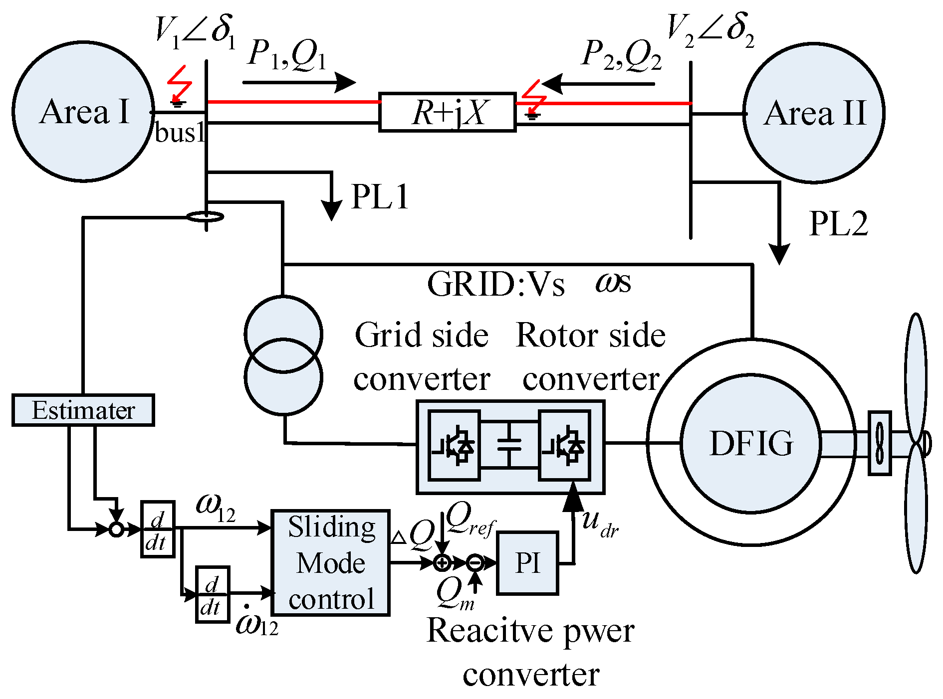
As shown in Figure 1, a two-area system containing a DFIG is considered in this section to illustrate inter-zone oscillations. With the use of a dual AC transmission line, the two zones are linked. The DFIG wind farm is considered to be incorporated in zone I for the purposes of this research.
The oscillating equation shown in (1), which is frequently used in [16,17], enable one to characterize the operation of a two-region system independent of wind power.
δ ˙ 12 = ω 12 ω ˙ 12 = 1 H 1 P m 1 P L 1 1 H 2 P m 2 P L 2 1 H 1 + 1 H 2 V 1 V 2 sin δ 12
where the generator rotor speed is given by the following formula, δ , and the generator rotor angle, ω , by the sign. The relative rotor angle and speed between the two zones are represented by the values ω 12 and δ 12 , respectively, with δ 12 = δ 1 δ 2 and ω 12 = ω 1 ω 2 . The total impedance of the dual circuit AC power lines makes up the reactance X . H 1 and H 2 represent the comparable inertia of region. Synchronous machine damping coefficient is ignored in (1). The damping coefficient is an uncertain factor in sliding-mode damping control design. The dynamic equation of the system composed of:
δ ˙ 12 = ω 12 ω ˙ 12 = 1 H 1 P m 1 + P w P L 1 1 H 2 P m 2 P L 2 1 H 1 + 1 H 2 V 1 V 2 sin δ 12
where Pw represents the power that the wind farm is actively producing. The angular difference between the two zones is linked to the active power delivered between them. Thus, reactive power transmitted from zone 1 to zone 2 is proportional to voltage, as seen in (3). For voltage fluctuations generated by reactive power, the bus voltage can be regulated by improving the way through the reactive power [18].
Q 1 = Q w + Q s 0 = V 2 2 V 1 V 2 cos δ 12 X
where reactive power Q 1 is the amount of energy moved from region 1 to region 2. Q w is the reactive power injected by DFIG, and Q s 0 is reactive power produced by capacitive compensators and synchronous generators. Under steady-state circumstances, both generators function simultaneously. Relative angle δ 12 and rotor speed ω 12 stay constant zero.
However, when there is a disturbance, the generator’s electrical and mechanical abilities become out of balance, causing power fluctuations in both areas. It is crucial to dampen such oscillations promptly to ensure the system’s stability. In this article, we implement a damping controller using a second-order sliding-mode control technique to change the amount of reactive power in DFIG.

3. Controller Design

For the most part, second sliding controllers are used to maintain zero relative degree 2 outputs or to prevent chattering while zeroing relative degree 1 outputs. To implement them effectively, one must take into account the first-time derivative of the output, which may make the method vulnerable to sampling disturbances. In this article, we examine these three issues and provide some common approaches to fixing them.

3.1. Selecting Variables

For dynamic systems such as the following:
x ˙ = a ( t , x ) + b ( t , x ) u , σ = σ ( t , x )
where x R n , u R is control; smooth functions a , b , σ and the dimension n are uncertain; and s is the sole output of n that can be measured. The expected relative degree is two [19]. The objective is to eliminate the output s in limited time and maintain σ 0 using a discontinuous, globally-bounded feedback control. For each finite input, system trajectories should be indefinitely extendible in time. The system is comprehended according to the Filippov sense [20].
Under these conditions, we compute the second derivative together with the trajectories of the two points (5).
σ ¨ = h ( t , x ) + g ( t , x ) u , h = σ ¨ u = 0 ,   g = u σ ¨ 0
where two unnamed smooth functions are g and h. Consider the circumstances of inputs and outputs.
0 < K m u σ ¨ K M ,   | σ ¨ | u = 0 | C
Be patient for some K m , K M , and C > 0. Keep in mind that (4) holds for any smooth system with the specified relative degree 2.
Evidently, the outlined issue cannot be resolved by a continuous feedback controller. Any continuous control u = φ ( σ , σ ˙ ) that allows for s and 0 has to satisfy the equality φ ( 0 , 0 ) = h ( t , x ) / g ( t , x ) whenever σ = σ ˙ = 0 holds. The simple autonomous linear system σ ¨ = c + k u ,   K m k K M ,   | c | C with φ ( 0 , 0 ) c / k will not respond to the controller.
The first-order derivative of the chosen sliding-mode variable as well as zeroing both are the goals of the second-order sliding-mode control algorithm. To assure control at = 0, the sliding variable is chosen based on the intended control aim. In this study, maintaining a constant angle between the two zones is referred to as damping power oscillations. In other words, it entails maintaining a zero value for the relative rotor speed ω 12 . Therefore, σ = ω 12 can be used as the sliding variable to establish the second-sliding mode σ = 0 . Assume that (3) is true universally. The differential inclusion is implied by (2) and (3).
σ ¨ [ C , C ] + K m , K M u
In most cases, a second-sliding controller may be seen as a controller for (4), where the goal is to reduce σ and σ ˙ to zero within some specified period. Consequently, the challenge lies in locating such feedback.
u = φ ( σ , σ ˙ )
The starting point of the phase plane is eventually reached by all paths starting at (7) and (8).
The Filippov notion of differential inclusion (7), (8) entails a particular enlargement of the right-hand vector set to meet specific convexity and semi-continuity constraints [21]. When σ continuous, Φ ( σ , σ ˙ ) is replaced by u in (7), which is being the convex closure of all feasible φ ( σ , σ ˙ ) limits obtained when the continuity point ( σ 1 , σ ˙ 1 ) approaches ( σ , σ ˙ ) . The function φ assumes Borel-measurability with a locally bounded domain. All sliding-mode control functions meet this criterion. Any absolutely continuous function ( σ ( t ) , σ ˙ ( t ) ) satisfying (4), (5) for almost all t is the solution.

3.2. Damping Controller Design

Modifying the DFIG’s active and reactive power changes bus voltage, including phase angle and magnitude. By supplying braking or accelerating torque in the opposite direction during the swing of synchronous machines, they may assist to attenuate oscillations if they are appropriately managed.
Through selecting the system dynamics for the two-zone power system shown in Figure 1, use angle 2 = 0 as the reference angle expressed in terms of the variables in Equation (1). The modulation variable is Qω. Thus, the system oscillation equation may be solved using the relationship shown in (3) in position of bus 1 voltage to obtain the results shown below.
ω ˙ 12 = 1 H 1 P m 1 P L 1 1 H 2 P m 2 P L 2 1 H 1 + 1 H 2 sin δ X cos δ V 2 2 sin δ cos δ Q w + Q s 0
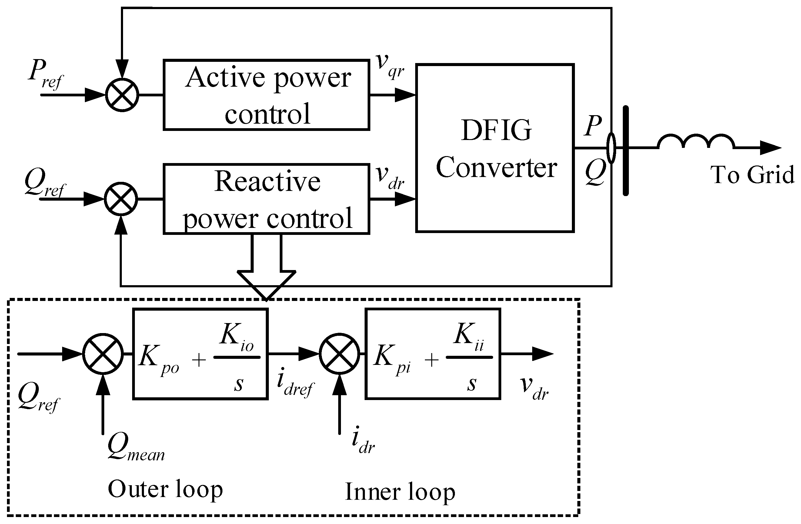
In this paper, reactive power Q w is modulated as a sliding-mode control variable for inter-area oscillations. The DFIG’s reactive power does not abruptly change because sliding-mode control calls for discrete control actions. As a result, it is not possible to perform direct control actions using reactive power. The reactive power is controlled using a dual-loop PI controller, which consists of an outer reactive power loop and an interior current loop [22]. Figure 2 depicts the control scheme that the DFIG reactive power reference Qref can be the actual control action used for the sliding damping control. If reactive power is used directly in the control loop, the relative degree can become significant. Therefore, the reactive power control loop’s dynamic variables use a first-order inertia loop. That allows the designed control to perform better in terms of control robustness to bounded systems.
The behavior of the first-order inertial response as it relates to dynamics used in the equivalent reactive control loop is equivalent to the dynamic behavior of a full-order model system [23]. As the doubly fed reactive control loop’s dynamic nature is shown, the whole system’s dynamic equations may be written as
δ ˙ = ω 12 ω ˙ 12 = 1 H 1 P m 1 P L 1 1 H 2 P m 2 P L 2 1 H 1 + 1 H 2 sin δ cos δ V 2 2 X Δ Q w Q w Q s 0 Δ Q ˙ w = u Δ Q w T
where u is the extra reactive power element (Qref) that is utilized to modify damping.
Qw is the wind farm’s rated reactive power in nominal operation. As a result, the wind farm’s reactive power is ΔQw + Qw. The degree of tsliding variable (σ = ω12) is 2, where
ω ¨ 12 = 1 H 1 + 1 H 2 V 2 2 X + Δ Q w + Q w + Q s 0 1 cos 2 δ ω 12 1 H 1 + 1 H 2 sin δ cos δ Δ Q w T + 1 H 1 + 1 H 2 sin δ T cos δ u = F ω 12 , δ , Δ Q w , t + G ( δ , t ) u F ω 12 , δ , Δ Q w , t = 1 H 1 + 1 H 2 sin δ cos δ Δ Q w T V 2 2 X + Δ Q w + Q w + Q s 0 1 cos 2 δ ω 12 G ( δ , t ) = 1 H 1 + 1 H 2 sin δ T cos δ
The objective of control is defined as selecting the variables u that brings the relative rotor speed and its first order to zero. Both the reactive power of the damping control (Qw) and the relative rotor ω 12 are zero in the steady state. Consequently, the fixed part F(0,δ,0,t) equals 0. Many second-order sliding-mode controllers can be utilized to 0 in unlimited time according to Equation (11). Such a controller is obviously resilient to any perturbation because Equation (11) ignores external disturbances. Therefore, the goal is to design a feedback control u that converges all trajectories in Equation (11) to the phase plane in finite time, at the origin σ = σ ˙ = 0 .
As can be seen from the above section, we need to select a second-order sliding control loop that can ensure that the parameters converge to zero in the phase plane of σ   and   σ ˙ . Consequently, the homogeneous analog of the terminal controller is an algorithm based on second-order sliding [24], and the control signal u can be chosen as
u = α σ ˙ + β | σ | 1 / 2 sign σ | σ ˙ | + β | σ | 1 / 2
The output of any uncertain single-input, single-output system may be controlled by a universal finite-time convergent controller with a known permanent relative degree. A control that is continuous everywhere and solely depends on σ = σ ˙ = = σ ( r 1 ) = 0 steers the tracking error to zero with the discontinuous function sign(σ) = 1 , σ > 0 1 , σ < 0 , where the variables α > 0 and β > 0 are the control gains. The terminal sliding-mode controller, which originally had a singularity at σ = 0, is a 2-sliding analog of this controller [25]. With the above control action, the second-order of sliding variable is described by
ω ¨ 12 = F ω 12 , δ , Δ Q w , t + G ( δ , t ) α sign σ ˙ + β | σ | 1 / 2 sign σ
To force and to zero in a finite period, the control gains must be greater than the size of the uncertainties in F and G.

4. Stability Derivation for Second-Order Sliding-Mode Controllers

In this section, the DFIG integration technique for a two-area power system is provided. Designing the damping controller for DFIG makes use of the second-order sliding mode.

4.1. Figures, Tables and Schemes

Assumptions on function conditions α, β > 0, αKmc > 0 and the inequality
α K m C 2 α K m β ρ + β 1 2 ρ 2 > 0
Controller (12) provides the second-sliding mode σ = 0 that holds for positive α > β , which is always the case for sufficiently huge α .
Denote ρ =σ/|σ|1/2. Then, the controller u is u = α(ρβ)/(|ρ| + β), and owing to the symmetry of the issue, it suffices to examine the situation in which σ > 0. ρ ˙ [ C , C ] K m , K M α ρ β | ρ | + β + 1 2 ρ 2 sign σ | σ | 1 / 2 , −∞ < ρ < ∞.
Due to the above assumptions, the rotational velocity ρ ˙ is always positive for negative or tiny positive ρ ; as a result, there is such a positive ρ 1 < β that the trajectories reach the area ρ 1 < ρ . It is now necessary to demonstrate that there is ρ 2 > β such that the inequality ρ ˙ < ρ 2 is true close to the point when ρ 2 = ρ . That is the precise circumstance (14). Therefore, conditions (14) allow for the creation and maintenance of the inequality ρ1 < ρ < ρ2.
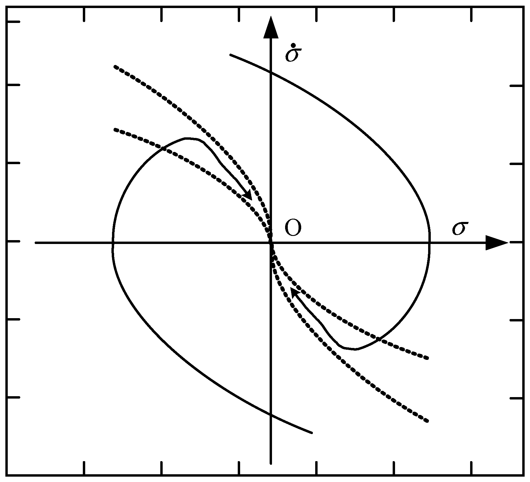
The only exception to this constant control is the origin. On the parabola σ ˙ + β | σ | 1 / 2 sign σ = 0 , it disappears. Each trajectory reaches the region between curves σ ˙ + β | σ | 1 / 2 sign σ = 0 and cannot exit it when an is large enough. These values are ρ 1 , ρ 2 and 0 < ρ1 < β < ρ2. The phase trajectory of the power system in the state space is shown in Figure 3. It is clear that the controlled system reached the sliding surface when both the sliding variable and its first order were set to zero.
Below is a description of the sequential impedance model for the power system, whereas the full-order DFIG model is employed in the simulation research. This model will be used in the simulation analysis part to demonstrate the efficacy of the developed sliding-mode-based DFIG damping controller in reducing power system oscillations.

4.2. Frequency Domain Analysis of DFIG

From the standpoint of the sequence impedance, we will study the effect of the control loop on the operational state of the DFIG and discuss the change in sequence impedance when the control parameters are changed.
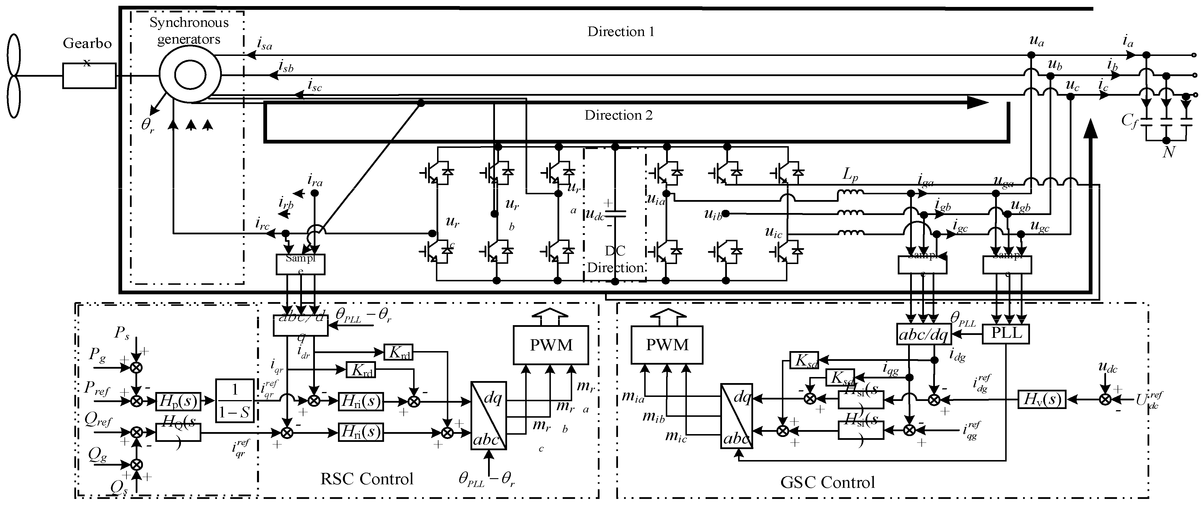
Figure 4 depicts the construction of the DFIG. The grid-side converter (GSC) is linked to the grid via the L-filter, whereas the rotor-side converter (RSC) is attached to the rotor of an asynchronous motor. Cdc and udc are the DC bus capacitance and voltage; U dc ref is the given DC bus voltage; ua, ub, uc and ia, ib, ic are the voltage and current at (point of common coupling)PCC; iga, igb, igc and uia, uib, uic are the output current and voltage at GSC port; isa, isb, isc are the generator stator side port currents; usa, usb, usc are the output modulation signals at RSC and GSC; and θpLL is the output modulation signal at RSC and GSC obtained by PLL sampling voltage locking at PCC. mra, mrb, mrc and mia, mib, mic are the output modulation signals of RSC and GSC, respectively; θpLL is the phase angle obtained by voltage locking at the PCC sampled by (phase-locked loop)PLL; and θr is the rotor electric angle measured by the position sensor. Hsi(s), Hri(s) are the GSC and RSC current loop PI control transfer functions, respectively, and Hu(s) is the voltage loop PI control transfer function. HP(s) and HQ(s) are the power loop PI control transfer functions, and Krd and Ksd are the current loop decoupling coefficients of RSC and GSC, respectively. The rotor rotational angular velocity is ωr differential angular velocity ωs = ω1 − ωr, and the differential rate is S = ωsr.
The system sequential resistance is shown below. The PCC steady-state operating voltage current ua = U1 and ia = I1 is overlaid with positive sequence voltage harmonics of frequency fp. Due to the dynamic DC bus procedure and the asymmetry of the dq control, harmonic small signal components will pass each other and couple multiple frequency harmonics within the unit [17,18]. The positive-sequence current harmonic Ip1 with fp and the negative-sequence current harmonic Îp2 with symmetric frequency fp − 2f1 about f1 are generated at the PCC and the voltage harmonic in the negative series Ûip2 with fp − 2f1 at the port, respectively. Define the voltage and current harmonics at the PCC as
u ^ a = 0 0 U ^ p 0 0 f p 2 f 1 f p f 1 f p f p + f 1 f p + 2 f 1 i ^ a = I ^ p 2 0 I ^ p 0 0 f p 2 f 1 f p f 1 f p f p + f 1 f p + 2 f 1
where Ûip2, φup and Ûp = Upe±jφup are the amplitude and phase, respectively, and the other variables are defined similarly.
Define the steady-state values of the GSC port output voltage and current as uia = Ui1, iga = Ig1, and the harmonics are
u ^ ia = U ^ ip 2 0 U ^ ip 0 0 f p 2 f 1 f p f 1 f p f p + f 1 f p + 2 f 1 i ^ ga = I ^ gp 2 0 I ^ gp 0 0 f p 2 f 1 f p f 1 f p f p + f 1 f p + 2 f 1
Due to the power balance on the DC bus, the network-side and machine-side current-voltage harmonics generate voltage harmonics of frequency f p f 1 on the DC bus, defining the DC voltage as the steady-state value Udc = U dc ref and harmonics u ^ dc :
u ^ dc = 0 U ^ dc 0 0 0 f p 2 f 1 f p f 1 f p f p + f 1 f p + 2 f 1
The RSC uses rotor voltage directional control with a rotor frequency of f r . The RSC port modulated voltage and current are affected by U ^ dc with positive sequence harmonics U ^ rp and I ^ rp with frequencies f p f r and negative sequence harmonics U ^ rp 2 and I ^ rp 2 with frequencies f p 2 f 1 + f r . The steady state values of RSC port current and voltage are defined as ura = Ur1, ira = Ir1 and harmonics as
u ^ ra = U ^ rp 2 0 U ^ rp 0 0 f p 2 f 1 + f r f p f 1 f r f p f r f p + f 1 + f r f p + 2 f 1 f r i ^ ra = I ^ rp 2 0 I ^ rp 0 0 f p 2 f 1 + f r f p f 1 f r f p f r f p + f 1 + f r f p + 2 f 1 f r
In constant conditions, the stator side current isa = Is1 and the harmonics are
i ^ sa = I ^ sp 2 0 I ^ sp 0 0 f p 2 f 1 f p f 1 f p f p + f 1 f p + 2 f 1

4.3. Asynchronous Induction Generator Impedance Modeling

Equations for the magnetic chain and voltage across the stator of a three-phase, statically connected asynchronous induction generator are
u sabc   = R s i sabc + d d t ψ sabc   u rabc K e = R r i rabc   K e + d d t ψ rabc   ψ sabc   = L ss i sabc + L sr i rabc K e ψ rabc   = L rs i sabc   + L rr   i rabc   K e
where Rs, Rr are the resistance values of each phase of the stator rotor winding; Ψsabc, Ψrabc are the three-phase magnetic chains of the stator-rotor; Lss, Lsr, Lrs, the stator-rotor winding’s mutual-inductance is denoted by Lrr; Ke is the stator-rotor turns ratio. Lss, Lsr, Lrs, Ke are the stator-rotor turns ratio. From the voltage equation and magnetic chain equation, we can obtain the generator. The impedance model is
i ^ ra = G 11 i ^ sa + G 12 u ^ a u ^ ra = G 21 i ^ sa + G 22 u ^ a
The modulation equation of GSC is
u ia = K gm u dc m ia
Consider the DC voltage outer-loop of GSC and obtain port output voltage. Then establish the relationship between GSC port output voltage. The relationship between the current is [17]
u ^ ia = P 1 u ^ dc + P 2 i ^ ga
The net-side filter inductor has the relationship on both sides.
u ^ ia = u ^ a + L i ^ ga
Where L = diag s L p , s j 2 ω 1 L p .
The current at the PCC can be expressed as
i ^ a i ^ ga i ^ sa
The impedance characteristics of the DFIG unit are shown by the voltage and current harmonics at the PCC point Y p , Y n , Y c and Y r . Y p and Y c are the positive sequence conductance, the negative sequence conductance, and the coupling conductance, and where Yp and Yc are
Y p ( s ) = I ^ p U ^ p Y c ( s ) = I ^ p 2 U ^ p
Meanwhile, the negative order conductance Yn and Yr can be obtained from Yp and Yc after discounting, obtained as:
Y r ( s ) = Y c * j 2 ω 1 s Y n ( s ) = Y p * ( s )

5. Simulation Research

In the following, we have carried out time-domain simulations from the power system to show how well the newly developed doubly fed motor damping controller for minimizing power system oscillations works in sliding mode. In the simulation, the DFIG drive train is modelled using the commonly used two-mass model.
In Figure 5, we see the first system under discussion, and a two-area power system with A 350 km transmission line connects the two locations. At steady state, there is 260 MW of transmitted electricity between the two locations. In Area I, a DFIG-based wind farm is linked to the grid as one aggregated DFIG. When the DFIG is producing at full capacity, its size is scaled down such that the whole system experiences no more than 10% wind penetration. The regulatory boundaries are 0.1 p.u. and the rated reactive power of DFIG is 0.5 p.u. The system parameters are shown in Table 1.
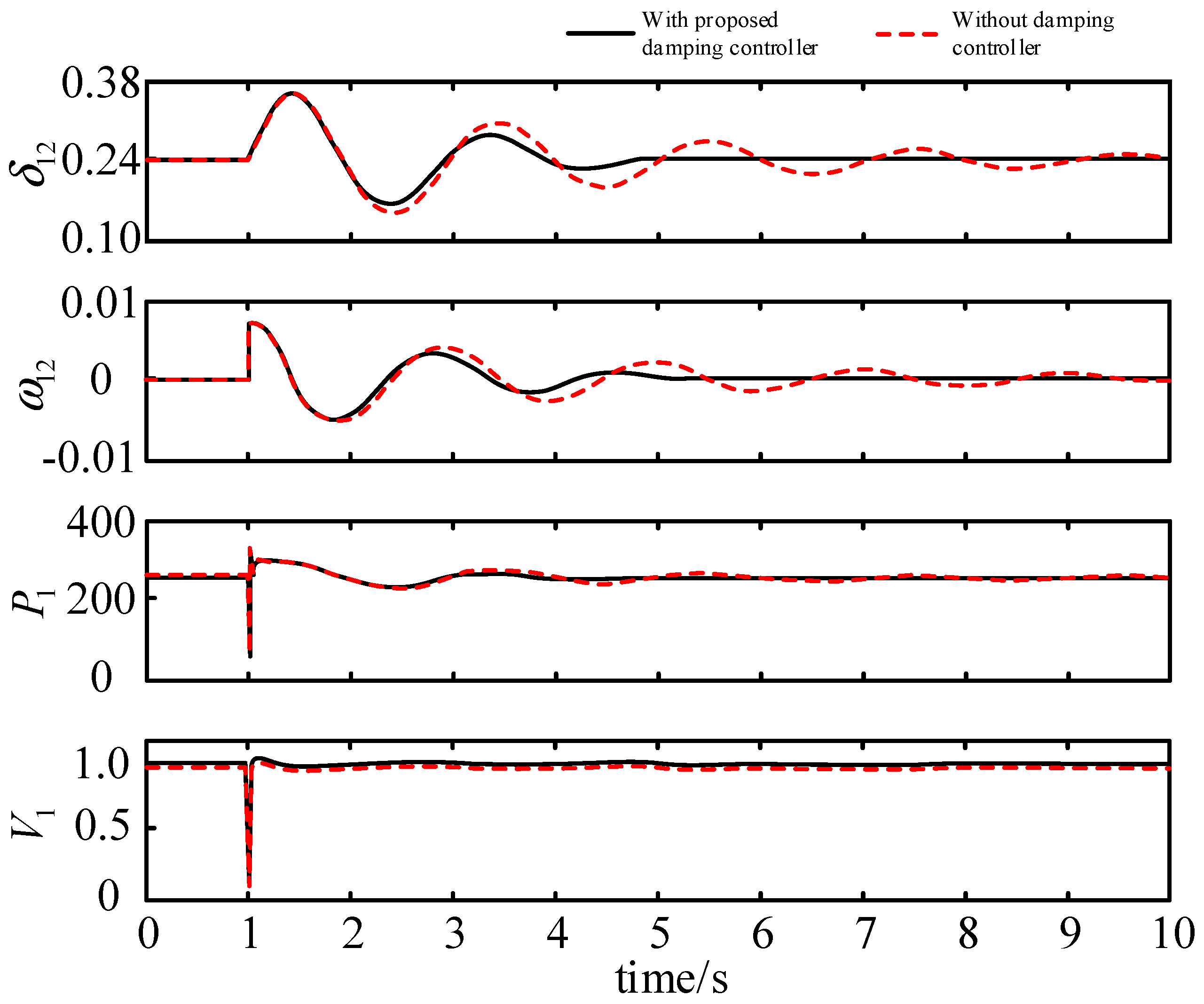
A three-phase fault is simulated which occurs at t = 1 s at a distance of 10 km from bus 1 and is cleared after 0.05 s. Inter-zone oscillations are caused by this fault. A damping control that utilized a sliding mode of second order was designed to be activated in reaction to the rotor angle differential produced at bus 1. Quickly stifling power oscillations is the job of the damping controller, which controls the DFIG’s reactive power.
Three symmetrical faults are set up in the system shown in Figure 5, with the fault point located at the midpoint of the contact line. Compare the transient response of the system when the DFIG has a damping controller and without a damping controller, as shown in Figure 6.
The above Figure 6 illustrates that reactive power oscillations are suppressed by injecting the DFIG’s modulated reactive power into the system through a sliding-mode dampening controller. Inter-area power oscillations caused by line failures have been effectively mitigated thanks to the upgraded DFIG.
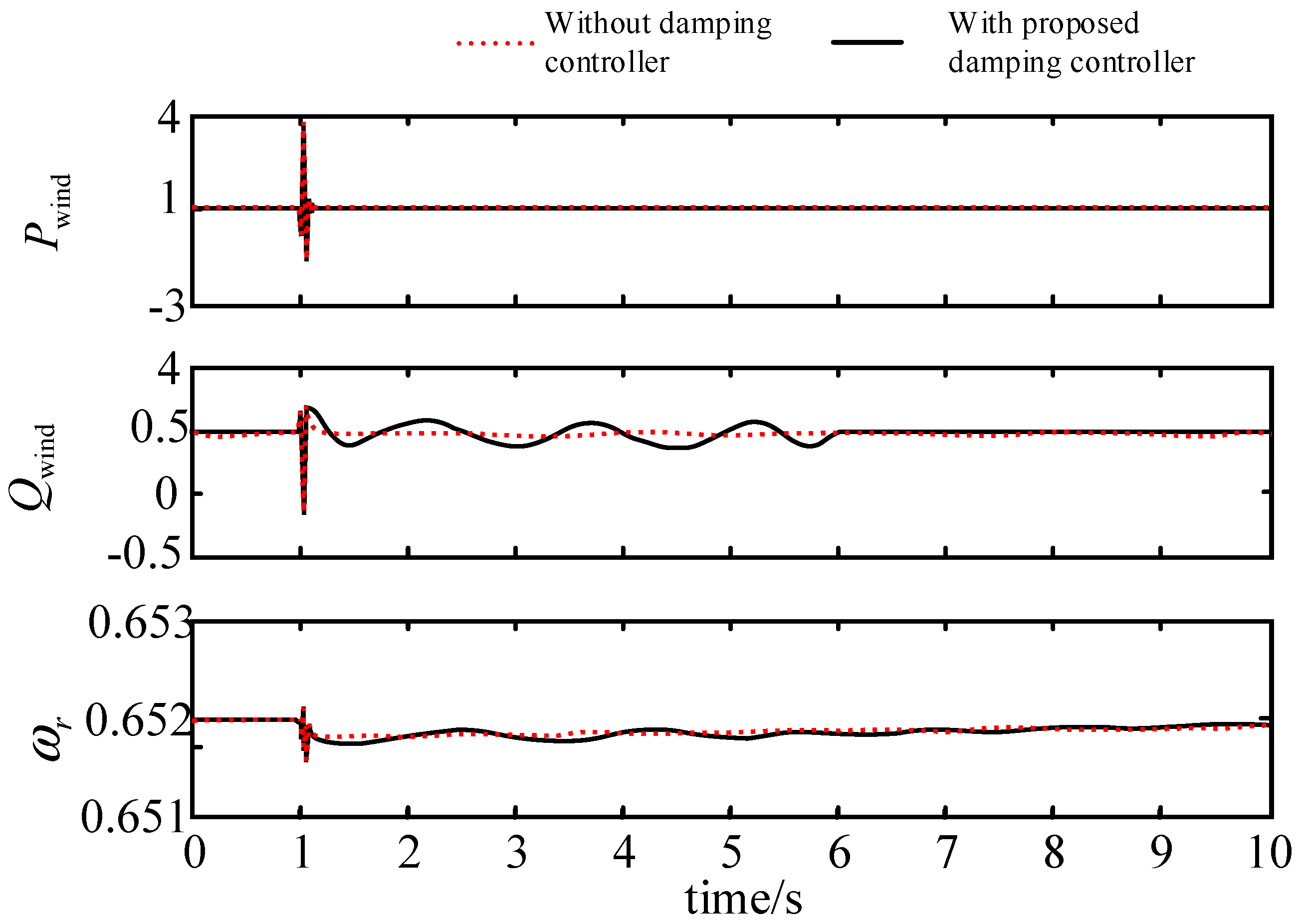
After adding reactive damping control, we examine the DFIG unit’s dynamic reaction to see how the unit’s output and stability performance change in the face of a problem.
Figure 7 depicts the transient performance of the DFIG, indicating that the proposed damping control scheme has essentially no influence on the active output power and motor torque of the DFIG.
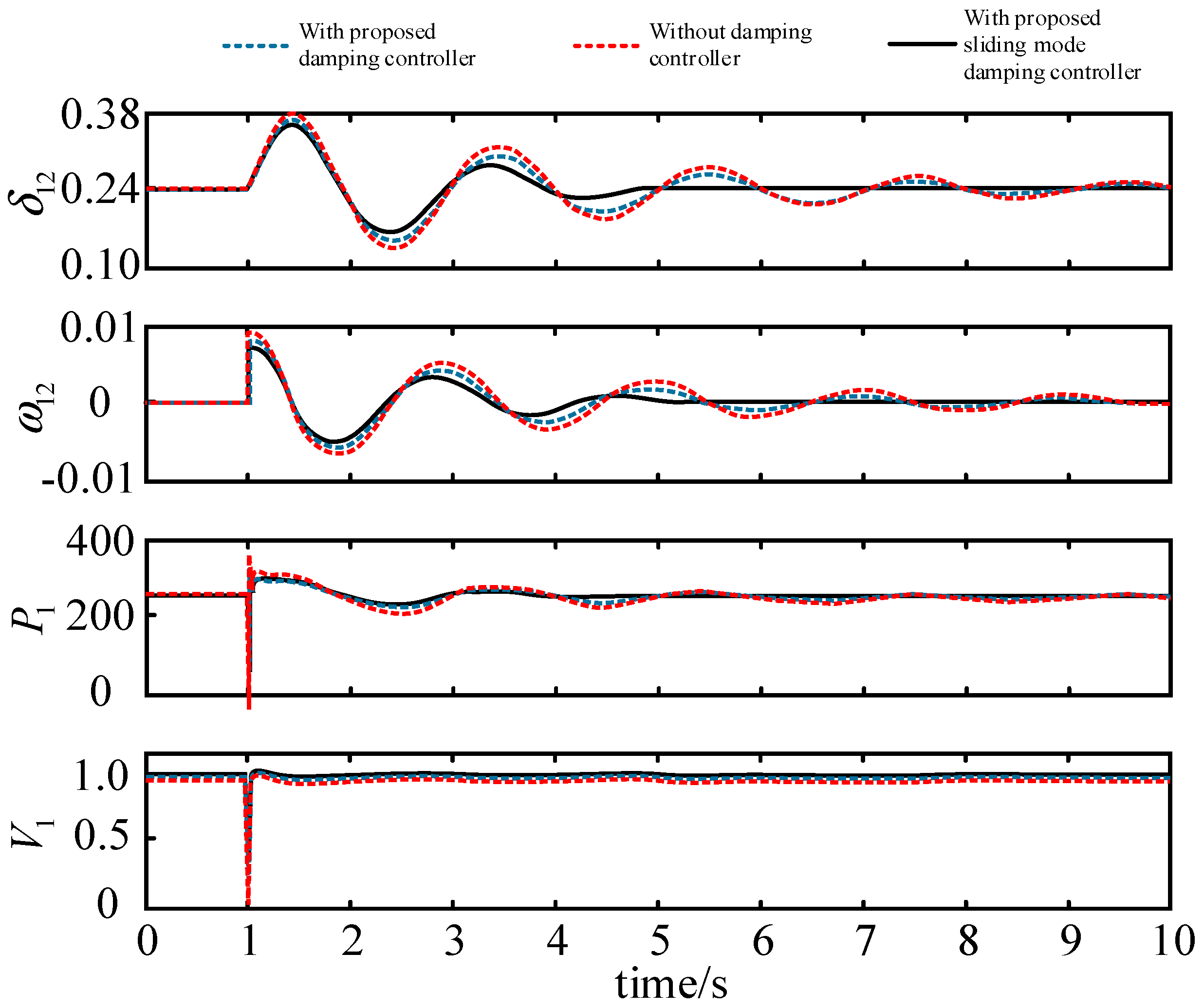
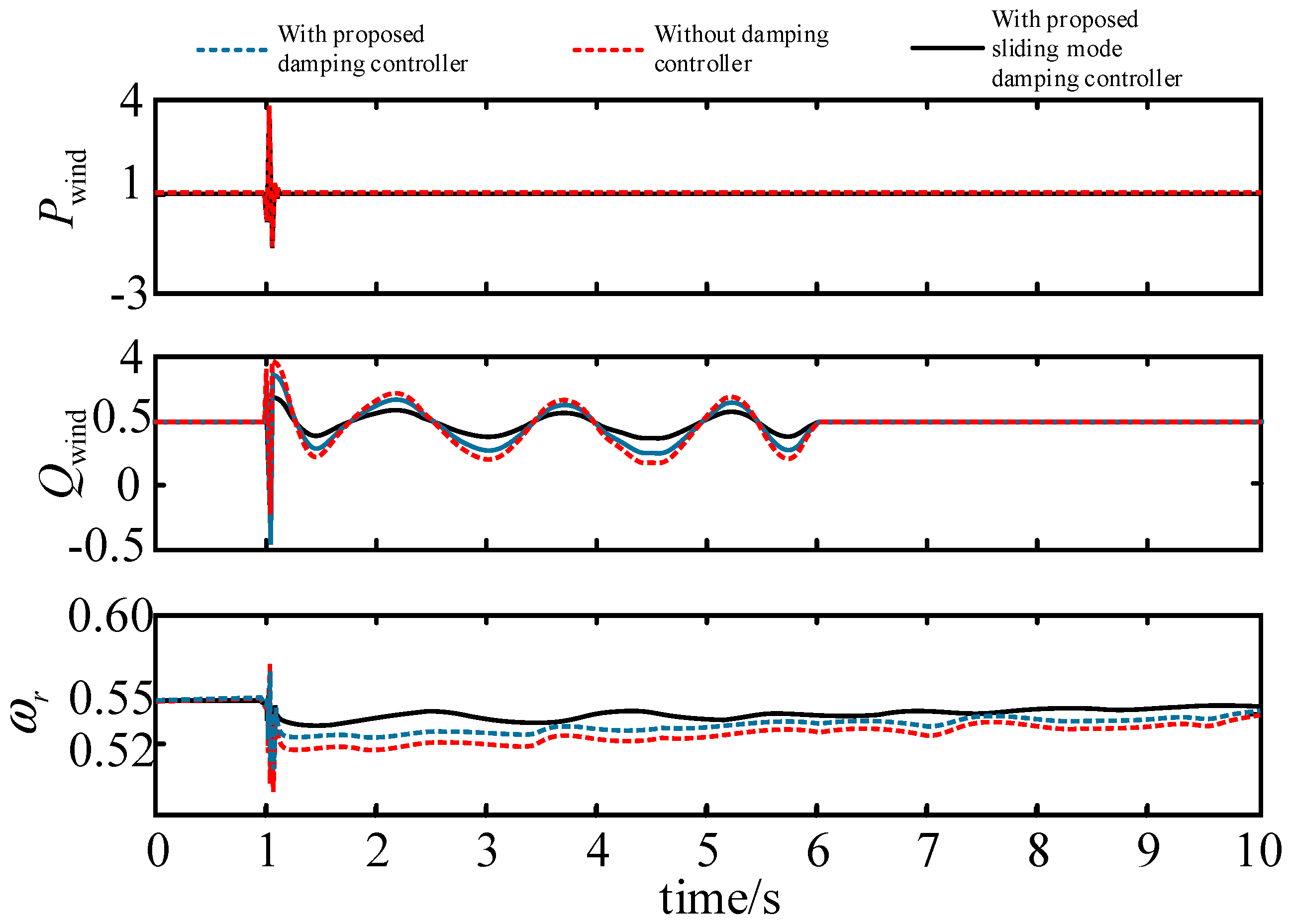
The above faults all occur close to the DFIG in the simulation model and are able to cause sufficient response from the DFIG step-down modeling loop. In the following, we study the faults that occur at the far end away from the DFIG equipment and vary the power transmitted by the contact line to verify the universality of the proposed control loop. The DFIG model with a damped control loop without a second-order sliding film is also introduced for comparison. When the three-phase short-circuit fault point occurs at two regional contact lines, the electrical quantities passing through the line and the power emitted by the DFIG are shown in Figure 8 and Figure 9.
From the dynamic responses in Figure 8 and Figure 9, it can be seen that the reactive power deficit in the system is significantly improved after the introduction of the damping control. However, the fluctuation time when returning to normal value in response to the dynamic response is not effective, while the time from the system to the return to stability is shortened after the introduction of the sliding mode improved damping control, which proves that the loop is effective in responding to the fluctuation of the system.
Even though the parameters of the control are within on reduced-order model of DFIG, simulation results on the full-order model simulations demonstrate that the proposed damping control is able to handle mechanism dynamic processes by unmodeled part failures. This is the case despite the fact that the reduced-order model of DFIG was used to design the parameters of the damping control loop.
The magnitude of the negative sequence impedance is less than the positive sequence impedance in the frequency range when the impedance is negatively resistive and capacitive. That is why all the publications focus on the positive kind of sequence impedance. Thus, only the positive sequence impedance is examined [26].
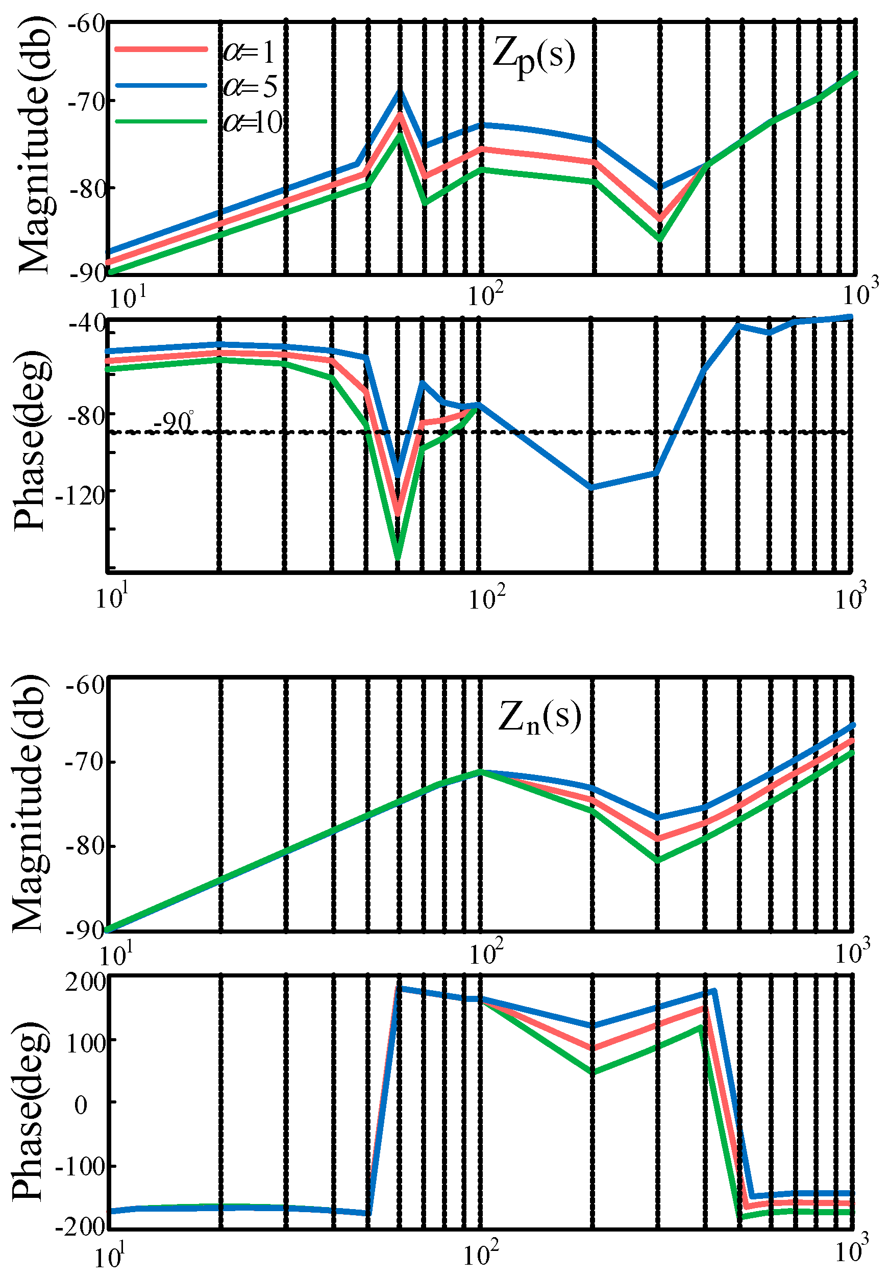
In the frequency range of 40–100 Hz, the phase shift between the positive and negative sequence impedances of doubly fed wind power systems is more than 90 degrees, which tends to interact with the inductive qualities of the weak grid and create oscillations throughout a broad frequency spectrum. Figure 10 shows the frequency response of the output impedance, with α varying from 1 to 10. A comparison shows that a larger leakage inductance increases the impedance amplitude and reduces the phase shift beyond 90° as the control parameter is varied from 1. However, when the parameter is chosen too large, too high an α causes a phase shift that makes the system unstable. This means that the α value should be chosen within a reasonable range.
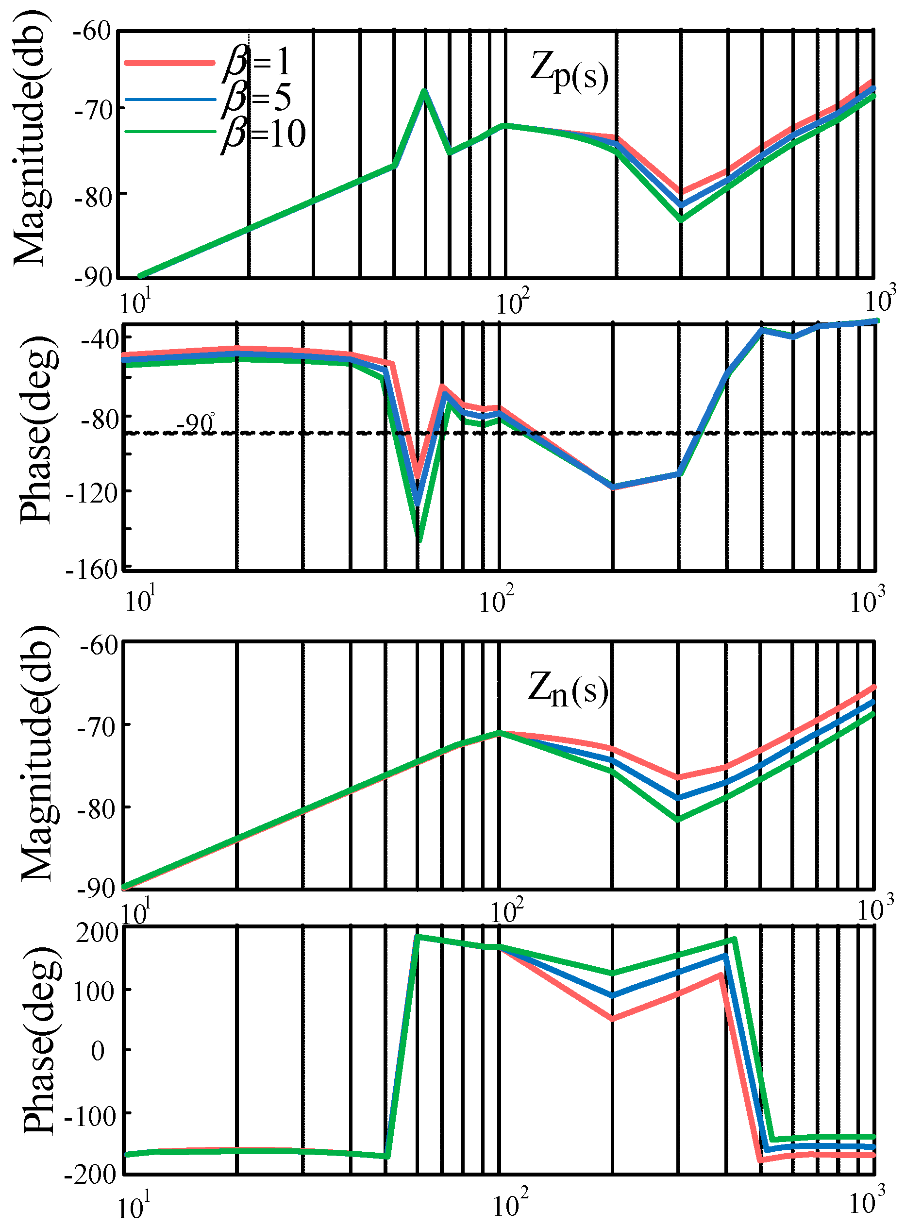
The frequency response of the output impedance is shown as a plot in Figure 11, where the value of goes from 1 all the way up to 10. Larger values increase both the impedance amplitude and the phase shift by more than ninety degrees when they are close to the fundamental frequency. The reliability of the system is compromised as a result. The values of α and β thus selected are given in Appendix A.

6. Conclusions

This article presents a DFIG-based damping control strategy for enhanced reactive power Q coordination. A reactive power modulation approach enhanced by a second-order sliding-mode algorithm is used by the control method. Changing the sliding mode of the second order gives the benefits of dither suppression and rapid reaction modifications. This maximizes the use of the DFIG’s damping control capacity, hence enhancing the damping performance. Using this damping controller, the stability of the system can be improved across a wide range of operating points and system parameters. This controller is better than traditional controllers because it can handle system uncertainty and unmodulated system dynamics better. The results of the simulation performed as part of a two-area power system study are then put through a sequential impedance analysis. The durability and efficiency of this damping controller are shown in the simulation results. The system power oscillations are dampened faster than they would have been without the damping controller. The simulation outcomes show that the proposed sliding-mode damping control controller on DFIG successfully drains the oscillation modes.

Author Contributions

Authors H.Z. and J.Y. understand the linguistic grammar of the thesis; authors H.W. and J.W. drew the graphics and made the formatting adjustments; and writer Q.L. was solely accountable for paper’s originality and composition. The whole team of writers has gone through the paper once again. All authors have read and agreed to the published version of the manuscript.

Funding

This research was funded by Natural Science Foundation of Xinjiang Autonomous Region, grant number 2020D01C068 and National Natural Science Foundation of China, grant number 52167016.

Data Availability Statement

The raw data suggest this study is accessible and will be made available with no restriction upon request by reaching the corresponding author.

Conflicts of Interest

The authors claim that they have no recognized conflicting economic interest or personal connections that may be seen as having influenced the research described in this study.

Nomenclature

DFIGdoubly fed induction generator
SSCIsub-synchronous control interaction
STATCOMstatic synchronous compensator
SVCstatic var compensator
δgenerator rotor angle
δ12relative rotor angle
ω12relative rotor speed
H1inertia of area 1
H2inertia of area 2
Pwwind farm power
Q1moved power
Qs0SG reactive power
QwDFIG reactive power
ssole output of n
a, b, σ smooth functions
GSCgrid side converter
RSCrotor side converter
PCCpoint of common coupling
CdcDC bus capacitance
UdcDC bus voltage
U dc ref given DC bus voltage
ua, ub, ucvoltage at PCC
ia, ib, iccurrent at PCC
iga, igb, igcoutput voltage at GSC port
uia, uib, uicoutput current at GSC port
isa, isb, iscgenerator stator side currents
usa, usb, uscgenerator stator side voltage
θpLLphase angle obtained by PLL
mra, mrb, mrcoutput modulation signals of RSC
mia, mib, micoutput modulation signals of GSC
Rs, Rrresistance values of winding
Yppositive sequence conductance
Ycnegative sequence conductance
HP(s), HQ(s)loop PI control transfer functions

Appendix A

The parameters of the designed sliding-mode damping controller are given below: α = 5.5; β = 0.01.

References

  1. Wu, C.; Zhang, X.-P.; Sterling, M. Wind power generation variations and aggregations. CSEE J. Power Energy Syst. 2022, 8, 17–38. [Google Scholar]
  2. Chen, P.; Qi, C.; Chen, X. Virtual inertia estimation method of DFIG-based wind farm with additional frequency control. J. Mod. Power Syst. Clean Energy 2021, 9, 1076–1087. [Google Scholar] [CrossRef]
  3. Ning, L.; Zhao, G.; Du, L.; Wang, S.; Chen, Y. Multi-Domain Optimal Scheduling of Wind Power Systems Based on Voltage Stability Constraints. In Proceedings of the 2020 International Conference on Artificial Intelligence and Electromechanical Automation (AIEA), Tianjin, China, 26–28 June 2020; pp. 1373–1384. [Google Scholar]
  4. Kunjumuhammed, L.; Pal, B.; Oates, C.; Dyke, K. Electrical oscillations in wind farm systems: Analysis and insight based on detailed modeling. IEEE Trans Sustain. Energy 2016, 1, 51–62. [Google Scholar] [CrossRef] [Green Version]
  5. Edrah, M.; Lo, K.L.; Anaya-Lara, O. Impacts of high penetration of DFIG wind turbines on rotor angle stability of power systems. IEEE Trans. Sustain. Energy 2015, 3, 759–766. [Google Scholar] [CrossRef] [Green Version]
  6. Qi, L.; Jiahui, W.; Haiyun, W.; Hua, Z.; Jian, Y. Effect of DFIG control parameters on small signal stability in power systems. Sci. Rep. 2023, 13, 2476. [Google Scholar] [CrossRef]
  7. Huang, H.; Nie, J.; Li, Z.; Wang, K. Distributed dynamic reactive power support system based on doubly-fed wind turbine. Power Syst. Prot. Control 2016, 44, 140–147. [Google Scholar]
  8. Mir, A.S.; Senroy, N. DFIG Damping Controller Design Using Robust CKF-Based Adaptive Dynamic Programming. IEEE Trans. Sustain. Energy 2020, 11, 140–147. [Google Scholar] [CrossRef]
  9. Tang, Y.; He, H.; Wen, J.; Liu, J. Power system stability control for a wind farm based on adaptive dynamic programming. IEEE Trans. Smart Grid. 2015, 6, 166–177. [Google Scholar] [CrossRef]
  10. Wang, X.; Liu, J.; Yang, P.; Ren, Z.; Zheng, B.; Chen, C.; Zhang, X. Mitigation of SSCI in the DFIG Based Large Scale Wind Power System with Optimized Multimode Damping Controller. In Proceedings of the 10th Renewable Power Generation Conference (RPG 2021), Online, 14–15 October 2021; pp. 666–671. [Google Scholar] [CrossRef]
  11. Benbouhenni, H.; Boudjema, Z.; Belaidi, A. Direct power control with NSTSM algorithm for DFIG using SVPWM technique. Iran. J. Electr. Electron. Eng. 2021, 17, 1–11. [Google Scholar]
  12. Surinkaew, T.; Ngamroo, I. Coordinated robust control of DFIG wind turbine and PSS for stabilization of power oscillations considering system uncertainties. IEEE Trans. Sustain. Energy 2014, 5, 51–62. [Google Scholar] [CrossRef]
  13. Wang, T.; Jin, M.; Li, Y.; Wang, J.; Wang, Z.; Huang, S. Adaptive Damping Control Scheme for Wind Grid-Connected Power Systems with Virtual Inertia Control. IEEE Trans. Power Syst. 2022, 37, 3902–3912. [Google Scholar] [CrossRef]
  14. Pourboghrat, F.; Farid, F.; Hatziadoniu, C.J.; Daneshdoost, M.; Mehdian, F. Local sliding control for damping interarea poweroscillations. IEEE Trans. Power Syst. 2004, 19, 1123–1134. [Google Scholar] [CrossRef]
  15. Darvish Falehi, A. An optimal second-order sliding mode based inter-area oscillation suppressor using chaotic whale optimization algorithm for doubly fed induction generator. Int. J. Numer. Model. Electron. Netw. Devices Fields 2021, 35, 2963. [Google Scholar] [CrossRef]
  16. Gebremedhin, A.; Mariona, Z. Power system analysis: The case of Albania. Int. J. Innov. Technol. Interdiscip. Sci. 2020, 3, 501–512. [Google Scholar]
  17. Kundur, P.S.; Malik, O.P. Power System Stability and Control; McGraw-Hill Education: New York, NY, USA, 2021. [Google Scholar]
  18. Hashmy, Y.; Yu, Z.; Shi, D.; Weng, Y. Wide-area measurement system-based low frequency oscillation damping control through reinforcement learning. IEEE Trans. Smart Grid. 2020, 11, 5072–5083. [Google Scholar] [CrossRef]
  19. Zehra, S.S.; Rahman, A.U.; Armghan, H.; Ahmad, I.; Ammara, U. Artificial intelligence-based nonlinear control of renewable energies and storage system in a DC microgrid. ISA Trans. 2022, 121, 217–231. [Google Scholar] [CrossRef] [PubMed]
  20. Filippov, A.F. Differential Equations with Discontinuous Righthand Sides: Control Systems; Springer Science & Business Media: Dordrecht, The Netherlands, 2013; p. 18. [Google Scholar]
  21. Xiong, X.; Kamal, S.; Jin, S. Adaptive gains to super-twisting technique for sliding mode design. Asian J. Control. 2021, 23, 362–373. [Google Scholar] [CrossRef] [Green Version]
  22. Yang, L.; Xu, Z.; Østergaard, J.; Dong, Z.Y.; Wong, K.P.; Ma, X. Oscillatory stability and eigenvalue sensitivity analysis of a dfig wind turbine system. IEEE Trans. Energy Convers. 2011, 26, 328–339. [Google Scholar] [CrossRef] [Green Version]
  23. Liao, K.; He, Z.; Xu, Y.; Chen, G.; Dong, Z.Y.; Wong, K.P. A Sliding Mode Based Damping Control of DFIG for Interarea Power Oscillations. IEEE Trans. Sustain. Energy 2017, 8, 258–267. [Google Scholar] [CrossRef]
  24. Mireles-Perez, C.; Gomez-Correa, M.; Cruz-Ortiz, D.; Ballesteros, M.; Salgado, I. First-order sliding mode control for second order systems with asymmetric constraints. In Proceedings of the 2022 10th International Conference on Systems and Control (ICSC), Marseille, France, 23–25 November 2022; pp. 227–232. [Google Scholar] [CrossRef]
  25. Pan, H.; Zhang, G.; Ouyang, H.; Mei, L. A novel global fast terminal sliding mode control scheme for second-order systems. IEEE Access 2020, 8, 22758–22769. [Google Scholar] [CrossRef]
  26. Xu, Y.; Nian, H.; Wang, T.; Chen, L.; Zheng, T. Frequency Coupling Characteristic Modeling and Stability Analysis of Doubly Fed Induction Generator. IEEE Trans. Energy Convers. 2018, 33, 1475–1486. [Google Scholar] [CrossRef]
Figure 1. DFIG grid-connected system.
Energies 16 03091 g001
Figure 2. DFIG reactive damping control strategy diagram.
Energies 16 03091 g002
Figure 3. Convergence trajectory of the second-order sliding-mode control.
Energies 16 03091 g003
Figure 4. Configuration and control of DFIG system.
Energies 16 03091 g004
Figure 5. Two-zone power system with DFIG sliding-mode control.
Energies 16 03091 g005
Figure 6. The dynamic reaction of line in case of a malfunction in bus 1.
Energies 16 03091 g006
Figure 7. The dynamic reaction of DFIG in case of a malfunction in bus 1.
Energies 16 03091 g007
Figure 8. The dynamic reaction of line in case of a malfunction in midpoint.
Energies 16 03091 g008
Figure 9. The dynamic reaction of DFIG in case of a malfunction in midpoint.
Energies 16 03091 g009
Figure 10. Frequency responses of output impedance as α changes.
Energies 16 03091 g010
Figure 11. Frequency responses of output impedance as β changes.
Energies 16 03091 g011
Table 1. Main parameters of the components.
Rated capacity S/MW1.5
DC voltage Udc/kV1.5
AC voltage V1/V563
Polar logarithm p2
Mutual inductance Lm(pu)4.1
Stator resistance rs(pu)0.007
Rotor resistance Rr(pu)0.005
Rotor inductance Llr(pu) 0.11
line inductor inductance XL/km0.25
line inductor resistance R/km0.023
line capacitance resistance nF /km12
Coupling inductor inductance L(pu)0.00178
Coupling inductor resistance R(pu)0.000929
Disclaimer/Publisher’s Note: The statements, opinions and data contained in all publications are solely those of the individual author(s) and contributor(s) and not of MDPI and/or the editor(s). MDPI and/or the editor(s) disclaim responsibility for any injury to people or property resulting from any ideas, methods, instructions or products referred to in the content.