Abstract
The heat extraction capacity of the self-circulation wellbore is usually small because of the limited heat exchange area. In the paper, the cluster horizontal well group technology was proposed to enhance the heat extraction capacity and decrease the unit cost. Based on the mathematical model of heat transfer, a numerical simulation model of wellbore self-circulation for heat extraction using cluster horizontal wells was established to study the influence of main factors on heat extraction capacity. The economic analysis of heat extraction and power generation was carried out according to the model of the levelized cost of energy. The results show that the enhancement of heat extraction capacity is limited after the injection rate exceeds 432 m3/d (1.59 MW/well). The inflection point of the injection rate can be determined as the design basis for injection-production parameters. When the thermal conductivity of formation increases from 2 to 3.5 W/(m·K), the heat extraction rate will increase 1.45 times, indicating that the sandstone reservoirs with good thermal conductivity can be preferred as the heat extraction site. It is recommended that the well spacing of cluster wells is larger than 50 m to avoid the phenomenon of thermal short circuit between wells, and the thermal conductivity of the tubing should be less than 0.035 W/(m·K) to reduce the heat loss of heat-carrying fluid in the tubing. Compared with a single well, a cluster horizontal well group can reduce the unit cost of heat extraction and power generation by 24.3% and 25.5%, respectively. The economy can also be improved by optimizing heat-carrying fluids and retrofitting existing wells.
1. Introduction
As clean and renewable energy, geothermal resources can be used as one of the important alternatives to fossil fuels in the future due to their vast reserves [1,2]. Hot dry rock (HDR) is widely distributed and has a high temperature, which is the most important field for future geothermal energy development [3]. The wellbore self-circulation technology is a potential method to extract heat from HDR. The heat-carrying fluid circulates in the enclosed space formed by the tubing and the annulus and is not in direct contact with the formation. It can avoid a series of problems of the EGS (enhanced geothermal system), such as the geochemical reactions between the heat transfer fluid and the geothermal reservoir and the fluid loss caused by hydraulic fracturing [4,5,6,7,8,9,10].
At present, the technologies for geothermal exploitation using a single well mainly include U-tube heat exchange technology [11] and wellbore self-circulation heat exchange technology (coaxial exchanger) [12]. However, compared with the wellbore self-circulation heat exchange technology, the U-tube heat exchangers are mostly used in the exploitation of shallow geothermal energy and have many problems such as large footprint, high thermal resistance, and low heat extraction rate [13]. Therefore, the U-tube heat exchangers are not suitable for the heat extraction of deep geothermal energy. Then, there have been many studies about the self-circulation wellbore for heat extraction in recent years. Beier et al. (2013) established an analytical model of a vertical temperature profile for a coaxial borehole heat exchanger and verified the results with experimental measurements [14]. Holmberg et al. (2016) established a numerical model of a coaxial borehole heat exchanger and compared the predicted results with the wellbore temperature profiles measured in the thermal response tests, and the influences of well depth, flow rate, and flow direction were studied [15]. Cui et al. (2017) analyzed the sensitivity of the new technology for self-circulation heat extraction in hot dry rock through numerical simulation and evaluated the economic feasibility of the new technology [16]. Gordon et al. (2018) built a vertical coaxial borehole heat exchanger using standard geothermal pipes, verified the semi-analytical model of coaxial heat exchangers, and compared the heat extraction capacities of heat exchangers with different inner diameters [17]. Dai et al. (2019) used a deep geothermal well in Tianjin to carry out a field heat extraction test using a coaxial open-loop design. The results show that the heat extraction capacity of this design was far greater than the theoretical value calculated by the heat transfer model [18]. Based on establishing a thermodynamic and economic evaluation model, Yildirim et al. (2019) conducted a parametric study on the influence of heat insulation tubing, temperature gradient, and other factors on heat extraction capacity and evaluated its economic performance for power generation [19]. Wang et al. (2021) proposed a novel multilateral-well coaxial closed-loop geothermal system (CCGS) that significantly improves the low heat extraction capacity but did not consider geothermal applications and cost calculations [20]. Pokhrel et al. (2021) studied the coaxial borehole heat exchanger system for geothermal power generation in Japan, and the results show that the thermal energy generated changes between 82 MWh and 194 MWh [21]. Based on the development of geothermal energy, some scholars have also conducted research on geothermal power generation. Alimonti et al. (2016) studied the heat extraction capability of water and heat transfer oil as heat-carrying fluids in wellbore heat exchangers and conducted a feasibility analysis of ORC power generation. The results show that the maximum thermal power is 1.5 MW and the net electric power is 134 kW [22]. Wang et al. (2019) studied the horizontal well technology for geothermal power generation, and the results show that the lowest power generation cost using isobutane as the heat-carrying fluid was 0.187 USD/(kW·h) [23]. Kurnia et al. (2021) studied the organic Rankine cycle (ORC) with abandoned oil wells to generate power and its economic analysis, but the cost of electricity was found to be almost double that of conventional geothermal technologies [24].
In summary, the current research on the wellbore self-circulation heat extraction technology has considered the influence of various factors, and the mathematical model and numerical simulation research on improving the heat extraction capacity have been constantly improved. However, the small contact area between wellbore and formation usually limits the thermal extraction capability. Therefore, a series of measures to improve the heat extraction capacity have been proposed, such as optimizing the heat-carrying medium and drilling horizontal wells. In addition, the feasibility analysis of geothermal power generation was carried out. Due to the high capital investment of wellbore self-circulation technology in HDR, increasing the heat extraction rate and reducing the unit heat extraction cost will be the key. However, there are few studies on economic analysis considering wellbore self-circulation heat extraction and the geothermal power generation of cluster horizontal wells, and there is no clear conclusion on the determination of wellbore spacing.
Therefore, based on the above problems, this study established a numerical simulation model according to the mathematical model of a cluster horizontal well for heat extraction. Secondly, the influence of key factors such as water injection rate, well spacing, and formation and tubing thermal conductivity on the heat extraction capacity and formation temperature field was studied. Finally, the economics of geothermal power generation by cluster horizontal wells were analyzed and evaluated.
2. Mathematical Model
Based on the principle of wellbore self-circulation for heat extraction, a mathematical model of unsteady heat exchange in the self-circulation wellbore for heat extraction was established. It includes wellbore continuity equations, wellbore pressure equations, and wellbore heat transfer equations. The influence of temperature and pressure changes on the physical properties of the heat-carrying fluid and the frictional heat between the heat-carrying fluid and the wellbore wall were also considered in the model.
2.1. Model Assumptions
In the model, it is assumed that only the heat conduction between formation and wellbore is considered. The initial temperature of the formation near the horizontal well section is uniform, and the initial temperature at the model boundary is constant. The influence of the inclined well section is neglected. The schematic of the heat transfer process in the self-circulation horizontal well is shown in Figure 1.
Figure 1.
Schematic diagram of typical wellbore section and heat transfer process. (a) Horizontal well; (b) local wellbore.
2.2. Governing Equations
2.2.1. Wellbore Continuity Equations
The heat-carrying fluid does not exchange with the formation fluid as it flows through the annulus and tubing. Therefore, at the same cross-section, the mass flow rate of the heat-carrying fluid is constant.
In the tubing, the continuity equation is as follows:
where qh is the mass flow rate of the heat-carrying fluid, kg/s; rtu1 is the inner radius of the tubing, m; l is the length of the well section, m; ρht is the density of the heat-carrying fluid in the tubing, kg/m3; vht is the flow rate of the heat-carrying medium in the tubing, m/s.
While in the annulus between the tubing and the casing, the continuity equation is as follows:
where rtu2 is the outer radius of the tubing, m; rca1 is the inner radius of the casing, m; ρha is the density of the heat-carrying fluid in the annulus, kg/m3; vha is the flow rate of the heat-carrying fluid in the annulus, m/s.
2.2.2. Wellbore Pressure Equations
The temperature and pressure of the heat-carrying fluid vary greatly in the flow, and the density and other parameters also change accordingly. Therefore, the mass flow rate of the fluid will also change, and the fluid is considered compressible fluid. According to the continuity equation and motion equation, the pressure distribution model of the heat-carrying fluid in annulus and tubing can be obtained, respectively.
In the tubing, the wellbore pressure equation is as follows [25]:
where pht is the pressure of the heat-carrying fluid in the tubing, Pa; dtu1 is the inner diameter of the tubing, m; t is the time, s; f is the hydraulic friction coefficient.
While in the annulus, the wellbore pressure equation is as follows:
where pha is the pressure of the heat-carrying fluid in the annulus, Pa; dca1 is the inner diameter of the casing, m; dtu2 is the outer diameter of the tubing, m.
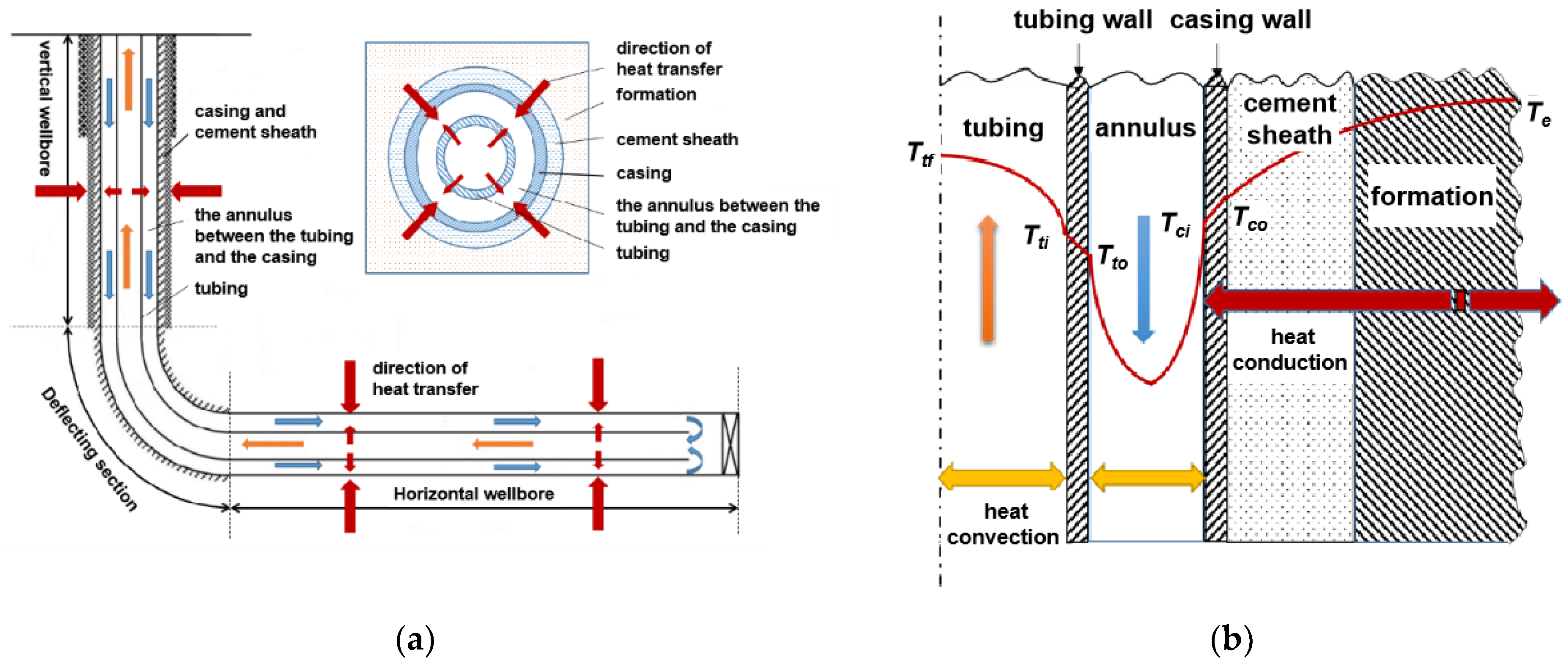
2.2.3. Wellbore Heat Transfer Equations
In the tubing, because the heat loss of the fluid cannot be completely interrupted by the heat insulation tubing, the heat change of the fluid in the tubing mainly includes: axially, the heat of the fluid flowing into and out of the control unit; radially, the heat loss of the fluid through convective heat transfer and the friction heat between the fluid and the inner wall of the tubing. According to the law of conservation of energy, the heat transfer equation is as follows:
where htu1,h is the convective heat transfer coefficient between the inner wall of the tubing and the fluid in the tubing, W/(m2·K); Tht is the temperature of the heat-carrying fluid in the tubing, K; Ttu is the wall temperature of the tubing, K; cht is the specific heat capacity of the heat-carrying fluid in the tubing, J/(kg·K); QF,tu is the heat power per unit length in the tubing, W [26].
On the tubing wall, the heat transfer equation is as follows:
where htu2,h is the convective heat transfer coefficient between the outer wall of the tubing and the annulus fluid, W/(m2·K); λtu is the thermal conductivity of the tubing, W/(m·K); Tha is the temperature of the heat-carrying fluid in the annulus, K; ρtu is the tubing density, kg/m3; ctu is the specific heat capacity of the tubing, J/(kg·K).
In the annulus, the heat change of the fluid mainly includes: axially, the heat of the fluid flowing into and out of the control unit; radially, the heat obtained by convection heat transfer between fluid and casing wall and tubing outer wall, and the friction heat between the fluid in annulus and wellbore wall. The heat transfer equation is as follows:
where hca1,h is the convective heat transfer coefficient between the inner wall of the casing and the annulus fluid, W/(m2·K); Tca is the temperature of the casing wall, K; cha is the specific heat capacity of the heat-carrying fluid in the annulus, J/(kg·K); QF,an is the heat power per unit length in the annulus, W.
In the cement sheath, there is no fluid flow between the cement sheath and the formation, and the main way of heat exchange is heat conduction. The heat transfer equation is as follows:
where rce1 is the inner radius of the cement sheath, m rce2 is the outer radius of the cement sheath, m; Tce is the temperature of the cement sheath, K; ρce is the density of the cement sheath, kg/m3; cce is the specific heat capacity of the cement sheath, kJ/(kg·K); λca,ce is the thermal conductivity of the casing and cement sheath, W/(m·K); λce,r is the composite thermal conductivity of cement sheath and formation, W/(m·K).
In the formation, the heat conductivity equation is a three-dimensional unsteady heat conductivity equation in cylindrical coordinates. When the thermal physical property parameters of the formation rock are constant, it is considered that the formation heat is mainly transferred to the wellbore in the radial direction. The heat transfer equation is as follows:
where Tr is the formation temperature, K; r is the radius of the formation around the wellbore, m; ρr is the formation density, kg/m3; cr is the specific heat capacity of the formation, kJ/(kg·K).
2.3. Initial and Boundary Conditions
In the real formation, the geothermal gradient is not constant. The geological model in this paper is simplified, assuming that the formation temperature increases linearly along the vertical direction. The initial formation temperature distribution is as follows:
where T0 is the ground surface temperature, °C; G is the geothermal gradient, °C/m; z is the vertical depth, m.
The formation boundary temperature is constant, and the boundary conditions of the formation are as follows:
where Tb is the boundary temperature of the formation around the wellbore and is constant, °C.
The contact surface between the casing wall and annulus fluid satisfies the following boundary conditions. In the circulation stage, the heat obtained through the annulus is equal to the heat conduction through the casing:
In the heat recovery stage, the heat flow out through the casing surface is equal to the heat flow into the annulus:
where λca is the thermal conductivity of the casing, W/(m·K); λha is the thermal conductivity of the heat-carrying fluid in the annulus, W/(m·K).
2.4. Solution and Validation
The heat exchange of a self-circulation wellbore in a single well can be calculated using a numerical solution method [22,27]. However, the solution cannot investigate the interaction of the near-wellbore temperature field between different wells in a well group. Hence, this study adopted the reservoir numerical simulation method, that is, the flexible well model of the CMG star module. This reservoir simulation module has the advantages of geological modeling and wellbore heat exchange calculation of multiple wells, which can simulate the inter-well interference on formation temperature [28]. To verify the prediction accuracy of the self-circulation wellbore using the flexible-well model, the HGP-A geothermal well in Hawaii, the United States, was selected for simulation and fitting [29]. The wellbore self-circulation for heat extraction in the HGP-A well was tested in 1991. The depth of the well was 876.5 m, the thermal conductivity of the formation was 1.6 W/(m·K), and the geothermal gradient is shown in Figure 2a. A heat insulation tubing was used in the wellbore, and its thermal conductivity was 0.06 W/(m·K). The water injection rate was 80 L/min, and the injection temperature was 30 °C. The measured and predicted wellbore temperatures after 93 h of fluid circulation are shown in Figure 2b. It can be seen that the simulated water temperature in the tubing fits well with the measured results by logging. The simulated and measured water temperatures at the wellhead are 46.27 °C and 45 °C, respectively. The error is 2.8%, indicating that the prediction accuracy of the simulation model is high.
Figure 2.
Fitting result of the wellbore temperature profile in geothermal well HGP-A. (a) Geothermal gradient; (b) wellbore temperature profile.
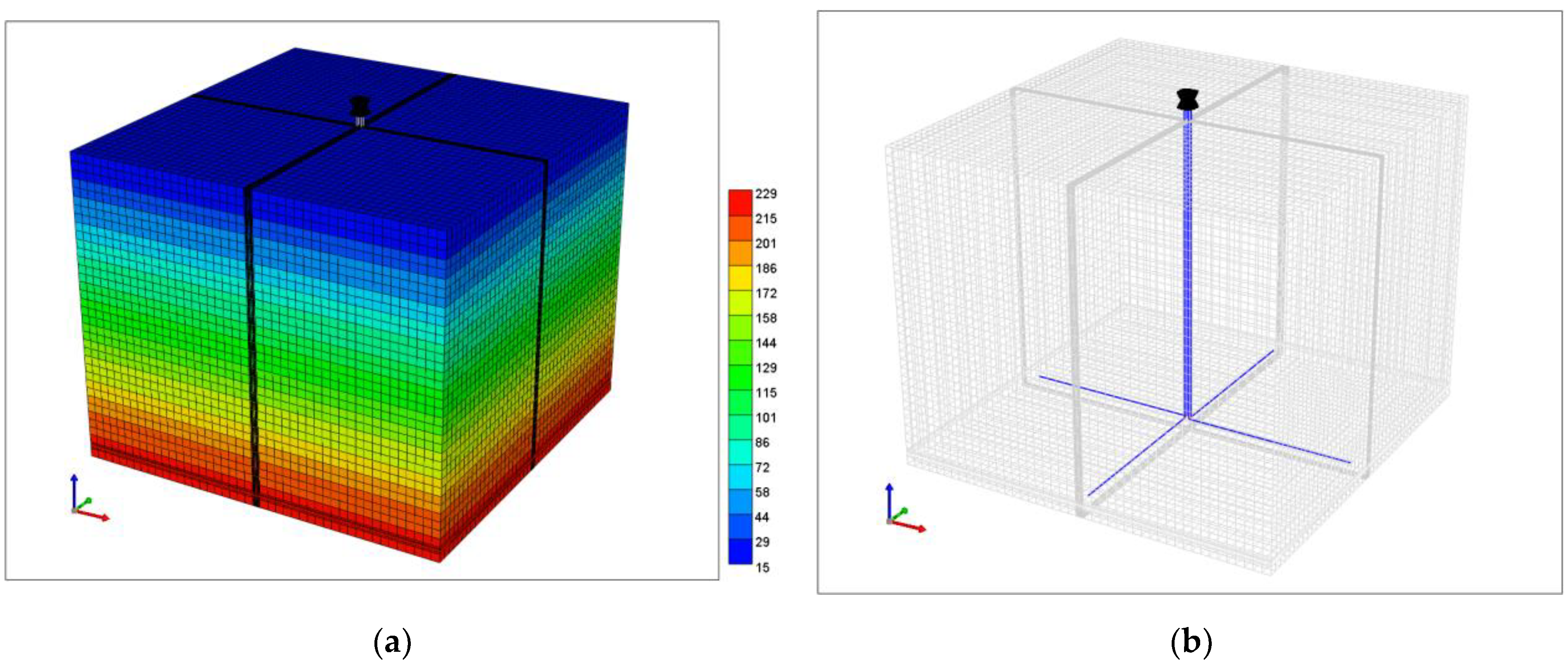
3. Numerical Simulation Model
3.1. Model Parameters
To investigate the feasibility and heat extraction characteristics of cluster horizontal well technology in deep geothermal energy development, a field-scale geological model was established according to the physical properties of a deep geothermal reservoir to simulate the wellbore self-circulation for heat extraction in HDR. In the geological model, there are two rock types. The upper part is a mudstone caprock with a thickness of 1500 m and a small thermal conductivity of 2.1 W/(m·K). The lower part is the HDR formation with a thickness of 2200 m and a large thermal conductivity of 3.2 W/(m·K). The porosity in the geological model was set to be 10%, and the permeability was set to 20 md. Other rock parameters of the formation are shown in Table 1.
Table 1.
Thermal physical properties of rock in the geological model.
The geological model size is 4500 m × 4500 m × 3700 m, which is divided into 67 × 67 × 49 grids. To accurately simulate the temperature field around the wellbore, the grids around the vertical wellbore and the horizontal wellbore are subdivided, and the grid size of the other parts is 100 m × 100 m × 100 m (Figure 3a). In the basic condition, there are four horizontal wells. The vertical well section is 3500 m with a spacing of 50 m. The horizontal well section is 2000 m and is perpendicular to each other (Figure 3b). The ground surface temperature in the model is 15 °C, the geothermal gradient is 0.06 °C/m, and the formation temperature near the horizontal well section is 221 °C. For each well, water was selected as the heat-carrying fluid, and the injection temperature and rate are 25 °C and 432 m3/d, respectively. The other parameters in the model are shown in Table 2.
Figure 3.
Geological model and cluster horizontal wells in the model. (a) Geological model (temperature field, °C); (b) cluster horizontal wells (the blue lines).
Table 2.
Parameters of wellbore self-circulation model.
3.2. Simulation Scheme
To assess the heat extraction performance of the self-circulation wellbore of cluster horizontal wells, the simulation scheme was designed. Sensitivity analysis of influencing factors such as injection rate, formation thermal conductivity, well spacing, and thermal conductivity of tubing was studied. The specific simulation scheme is shown in Table 3.
Table 3.
Numerical simulation scheme of self-circulation.
4. Simulation Results and Analysis
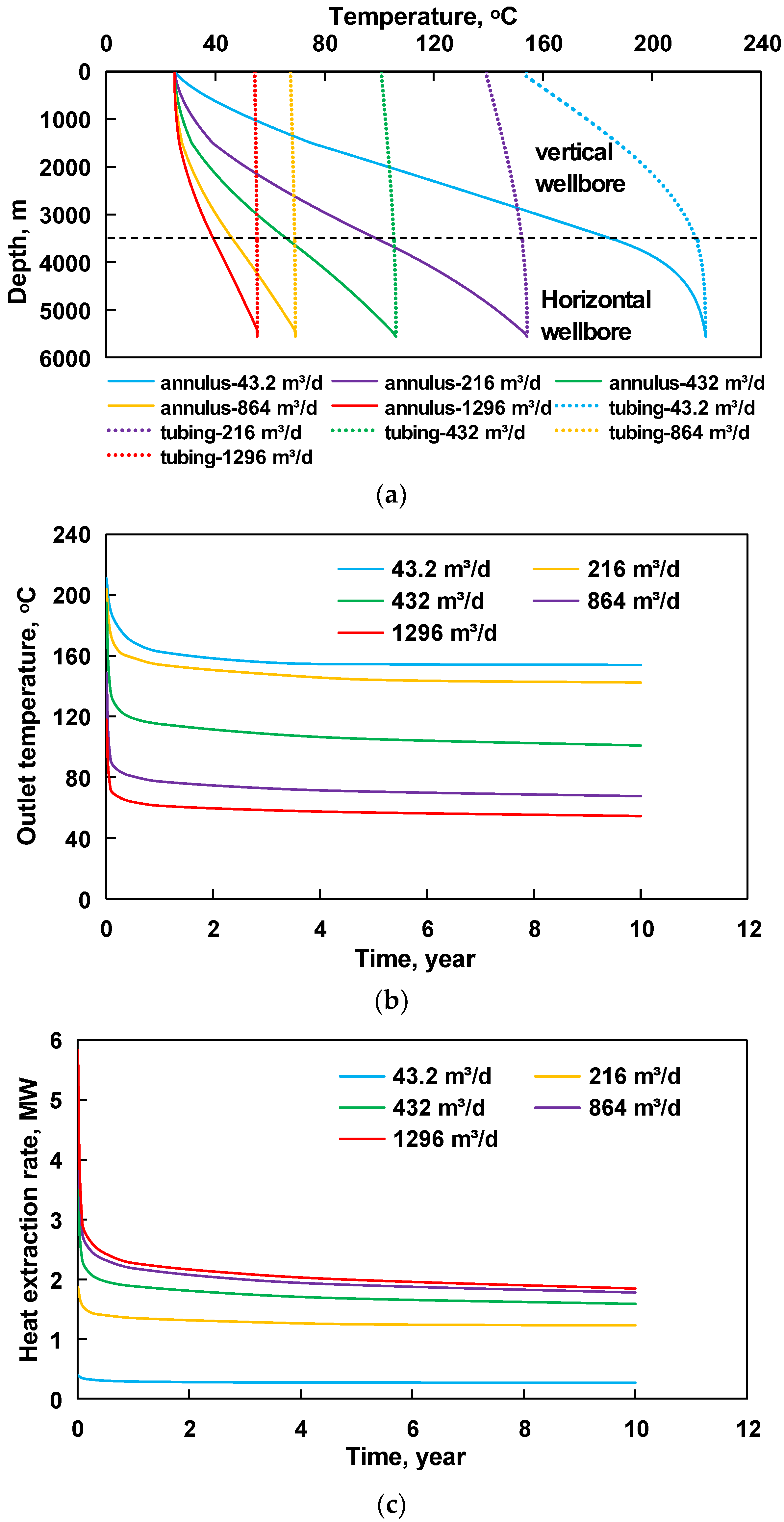
4.1. Water Injection Rate
Due to the symmetrical distribution of the four horizontal wells, only one well was taken as an example to analyze the heat extraction performance. The temperature distribution along the wellbore, the outlet temperature, and heat extraction rate at different injection rates are shown in Figure 4. It can be seen from Figure 4a that the injected water extracts heat from the geothermal reservoir in the annulus, and the water temperature gradually increases and reaches a peak at the bottom of the well. When the water returns to the surface through the tubing, a part of the heat in the water is lost to the annulus, and the wellhead temperature decreases. At a low injection rate, the outlet temperature is higher, but the heat loss in the tubing is relatively large. In contrast, an excessive water injection rate will lead to a lower outlet temperature, which is not conducive to geothermal utilization such as power generation. In addition, the outlet temperature drops rapidly in the initial stage and then tends to be stable, as shown in Figure 4b. The outlet temperature and heat extraction rate of a single well with an injection rate of 432 m3/d are 100.9 °C and 1.59 MW, respectively. When the injection rate exceeds 432 m3/d, the heat extraction rate increases slowly with the increase in the injection rate, indicating that there should be a reasonable fluid injection rate for heat extraction. The conclusion obtained is consistent with Cui’s research rule; that is, the heat extraction rate is essentially stable when the injection rate increases to a certain inflection point [16]. An excessive water injection rate is not necessary.
Figure 4.
Influence of water injection rate on heat extraction performance. (a) Wellbore temperature distribution; (b) outlet temperature; (c) heat extraction rate.
Figure 5 shows the formation temperature around the horizontal well after ten years of heat extraction at an injection rate of 432 m3/d. It can be seen that the formation temperature around the wellbore drops significantly, and the affected range is about 40 m.
Figure 5.
Formation temperature field around the horizontal well after 10 years.
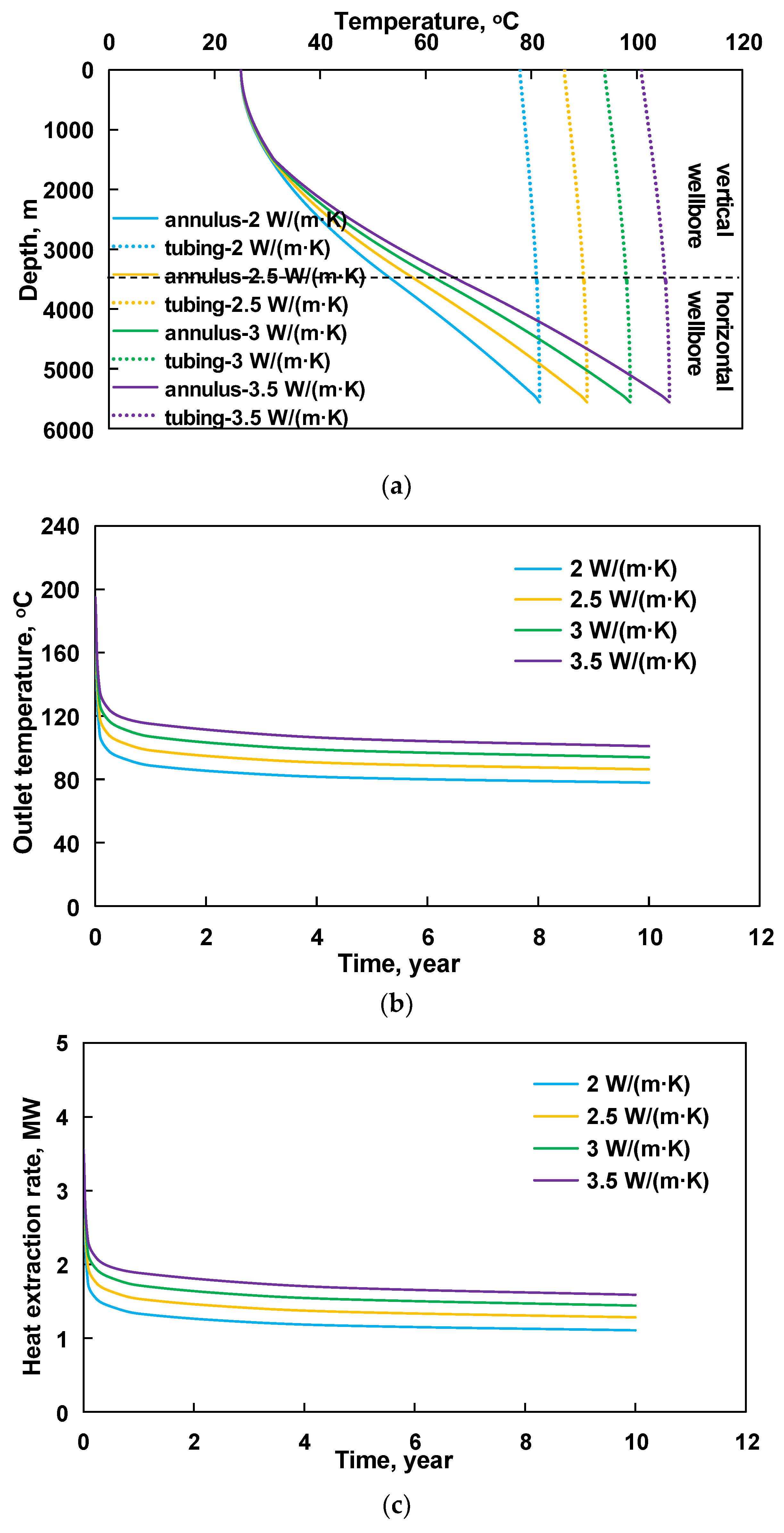
4.2. Thermal Conductivity of Formation
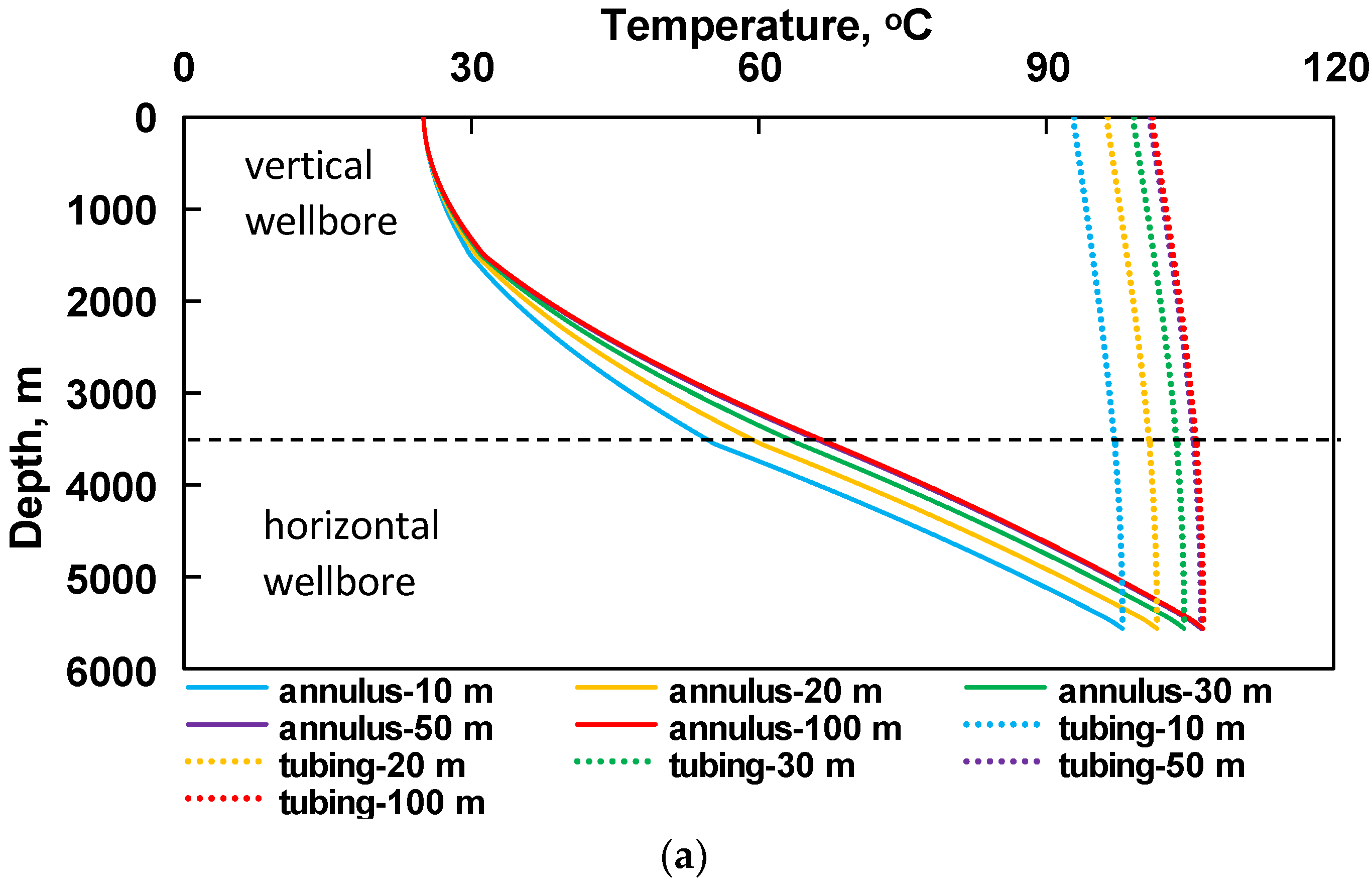
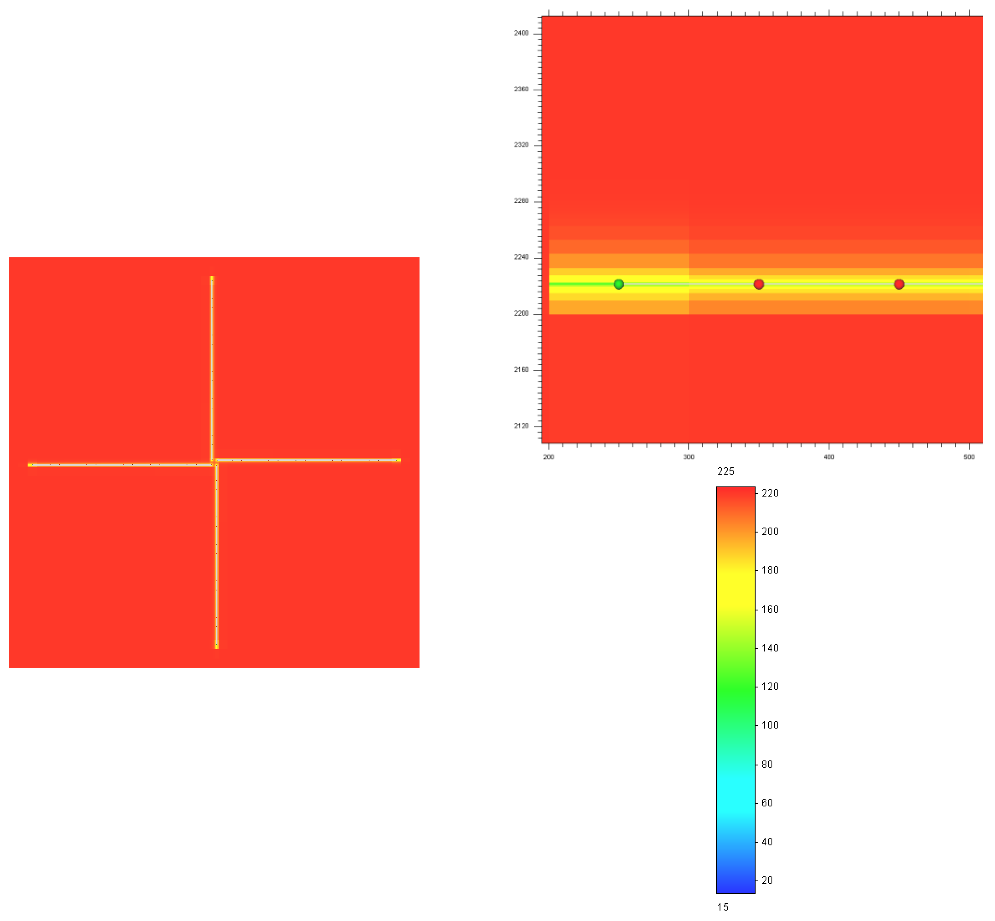
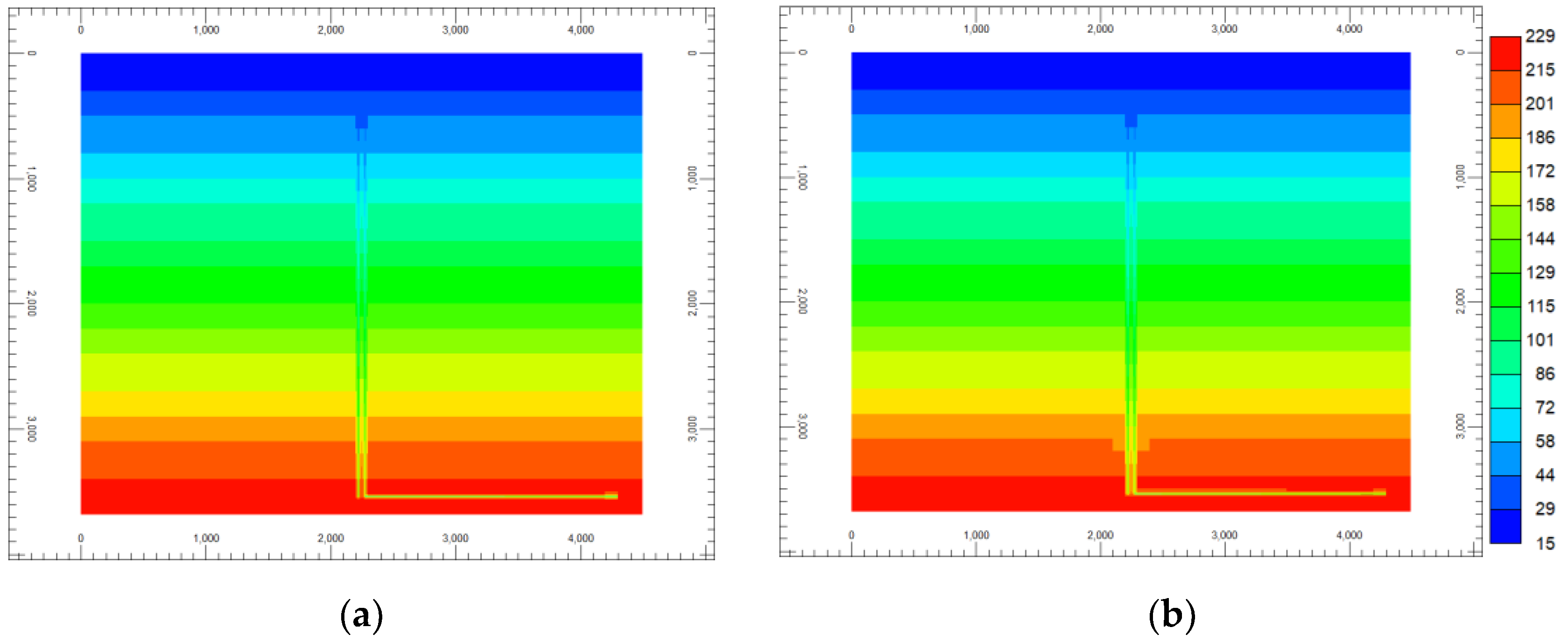
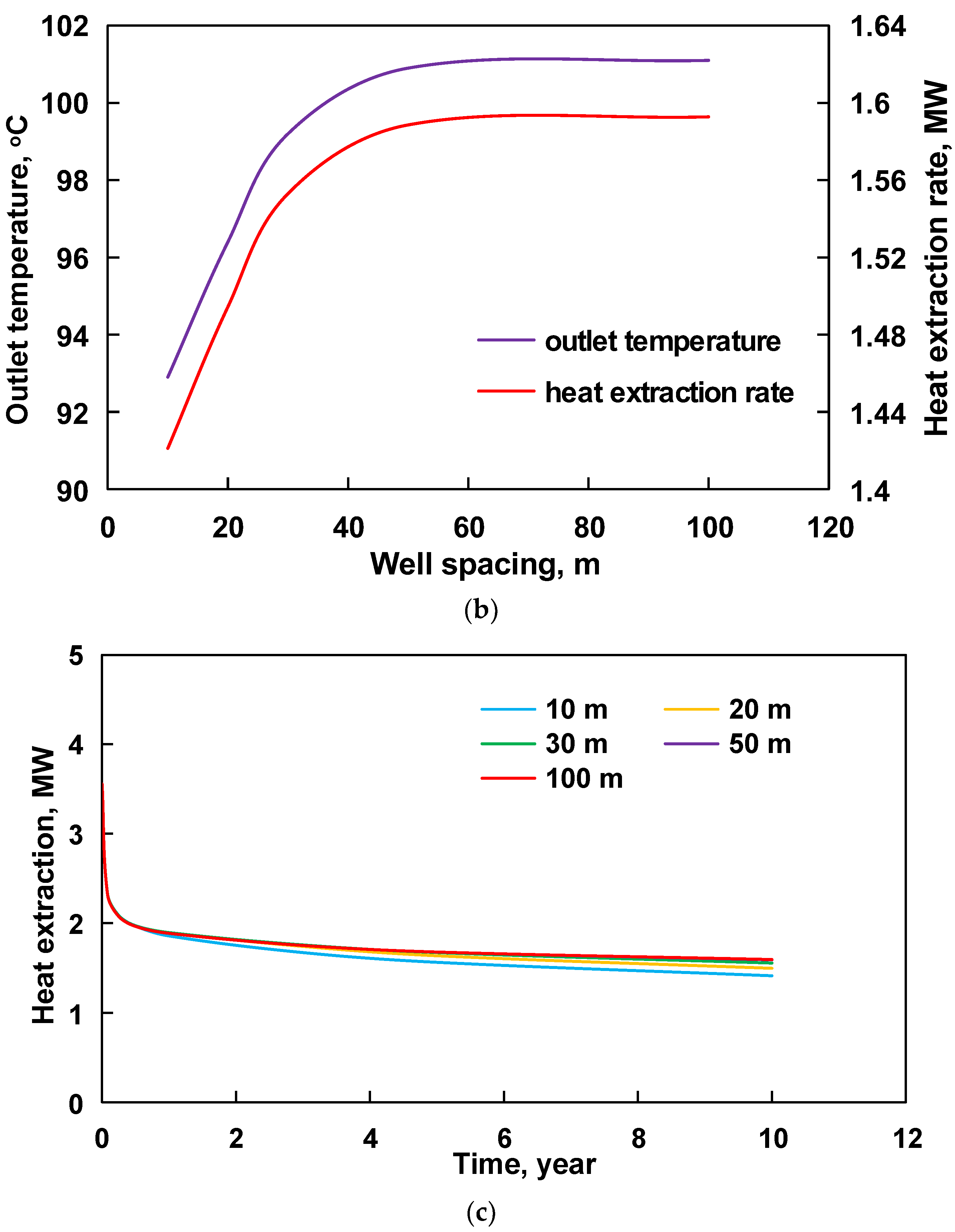
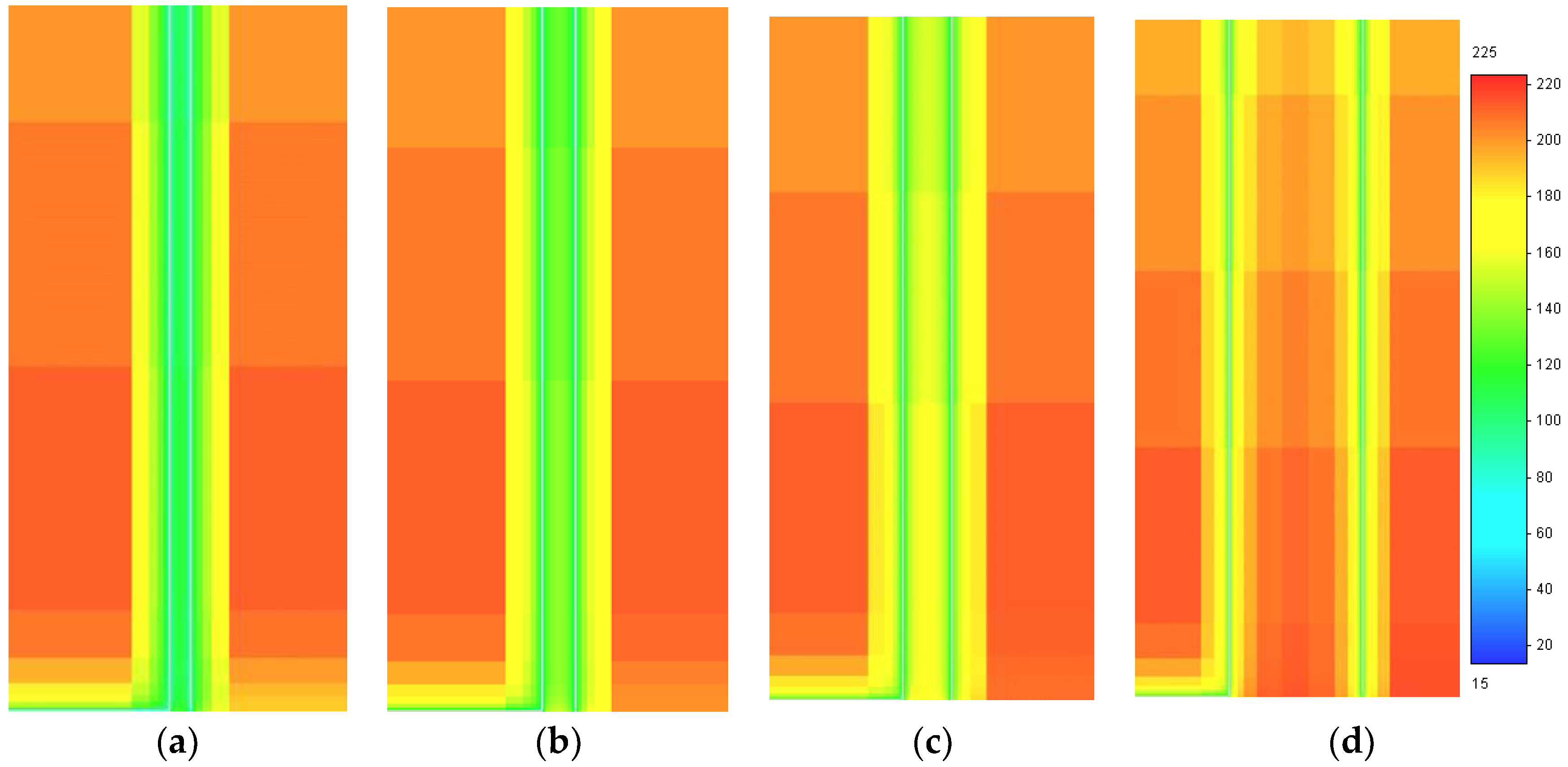
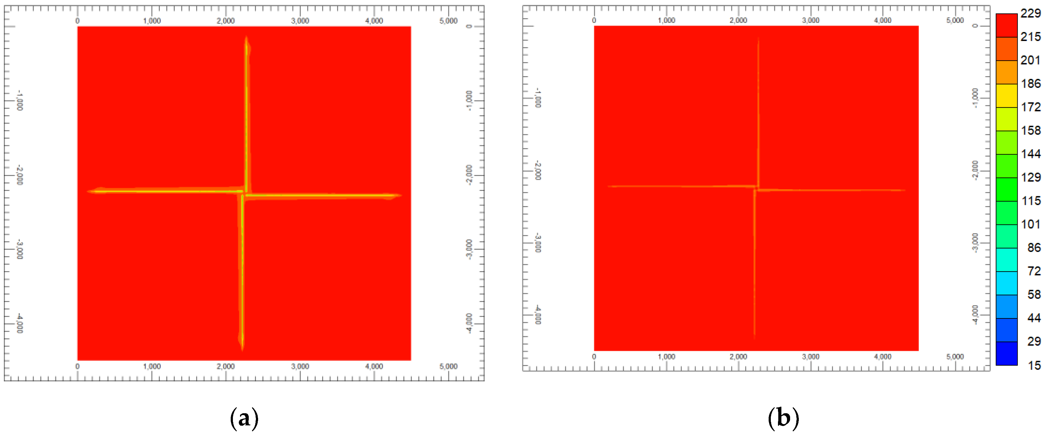
The HDR is widely distributed, and its lithology is mainly metamorphic rock or crystalline rock. Different types of HDRs have different thermal conductivity, which has an important effect on heat transfer. Figure 6 shows the wellbore temperature distribution, outlet temperature, and heat extraction rate at different formation thermal conductivity. With the increase in the formation thermal conductivity, the outlet temperature and heat extraction rate increase accordingly. The reason is that the formation with better thermal conductivity can timely replenish the lost heat around the wellbore. When the formation thermal conductivity is 2 W/(m·K), the outlet temperature and the single-well heat extraction rate are 77.9 °C and 1.1 MW, respectively, which are much lower than those at 3.5 W/(m·K) (100.9 °C and 1.59 MW). The heat extraction rate of the latter will be about 1.45 times the former. Figure 7 shows the formation temperature field at typical formation thermal conductivity. It can be seen that the formation with better thermal conductivity has a greater temperature drop around the wellbore. In a previous study, Song et al. compared the effect of formation rock thermal conductivity on geothermal exploitation [30]. The conclusion is that the thermal power of granite (4 W/(m·K)) is 132.35% higher than that of shallow soil (1 W/(m·K)), which indicates that the CBHE (coaxial borehole heat exchanger) system is more suitable for the development of deep geothermal resources. Therefore, according to the results in this section, it is feasible to develop HDR geothermal reservoirs with good thermal conductivity by using cluster horizontal wells.
Figure 6.
Influence of formation thermal conductivity on heat extraction performance. (a) Wellbore temperature distribution; (b) outlet temperature; (c) heat extraction rate.
Figure 7.
Formation temperature field at typical thermal conductivities of formation. (a) 2 W/(m·K); (b) 3.5 W/(m·K).
4.3. Well Spacing
Well spacing is a critical factor affecting the interference of the inter-well temperature field. As shown in Figure 8, the wellbore temperature will increase with the increase in the vertical wellbore spacing. The outlet temperature and single-well heat extraction rate with a well spacing of 10 m are 92.9 °C and 1.42 MW, respectively. When the well spacing is increased to 50 m, the outlet temperature and single-well heat extraction rate can reach 100.9 °C and 1.59 MW, respectively. It can be seen that the heat extraction rate can be increased by 12% (10 m to 50 m) with different well spacing. If the well spacing is small, the temperature range of the formation around the vertical wellbores will overlap after a short time of heat extraction, leading to a thermal short circuit of the inter-well. With the increase in the heat extraction time, the inter-well interference effect caused by the thermal short circuit becomes more significant, which has an important impact on the outlet temperature and the heat extraction rate. However, as the well spacing gradually increases, the effect of the thermal short circuit gradually decreases. The thermal-short-circuit effect with a well spacing of 30 m is relatively weak. When the well spacing is increased to 50 m, there is no effect on the heat extraction rate (Figure 9). Therefore, a reasonable well spacing should be determined according to the specific field conditions.

Figure 8.
Influence of well spacing on heat extraction performance. (a) Wellbore temperature distribution; (b) outlet temperature; (c) heat extraction rate.
Figure 9.
Formation temperature field around the wellbore at different well spacings. (a) 10 m; (b) 20 m; (c) 30 m; (d) 50 m.
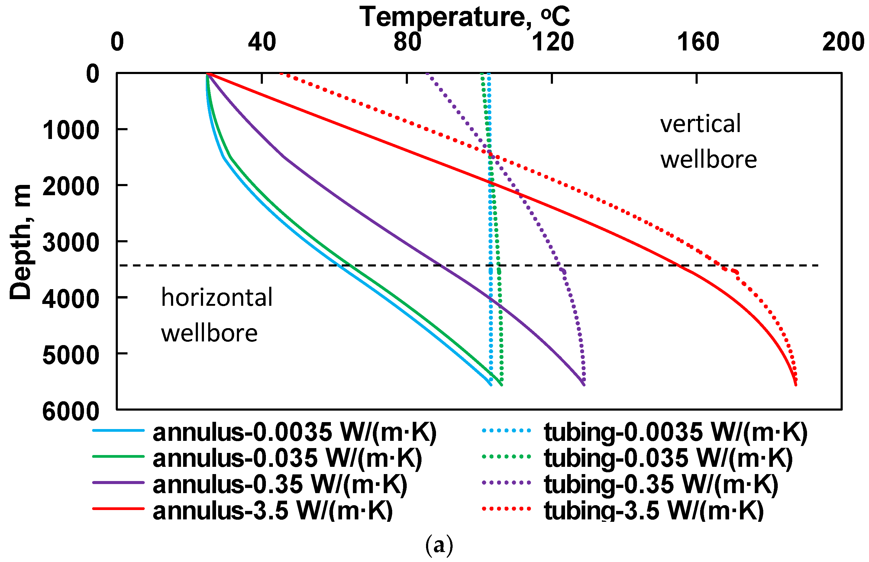
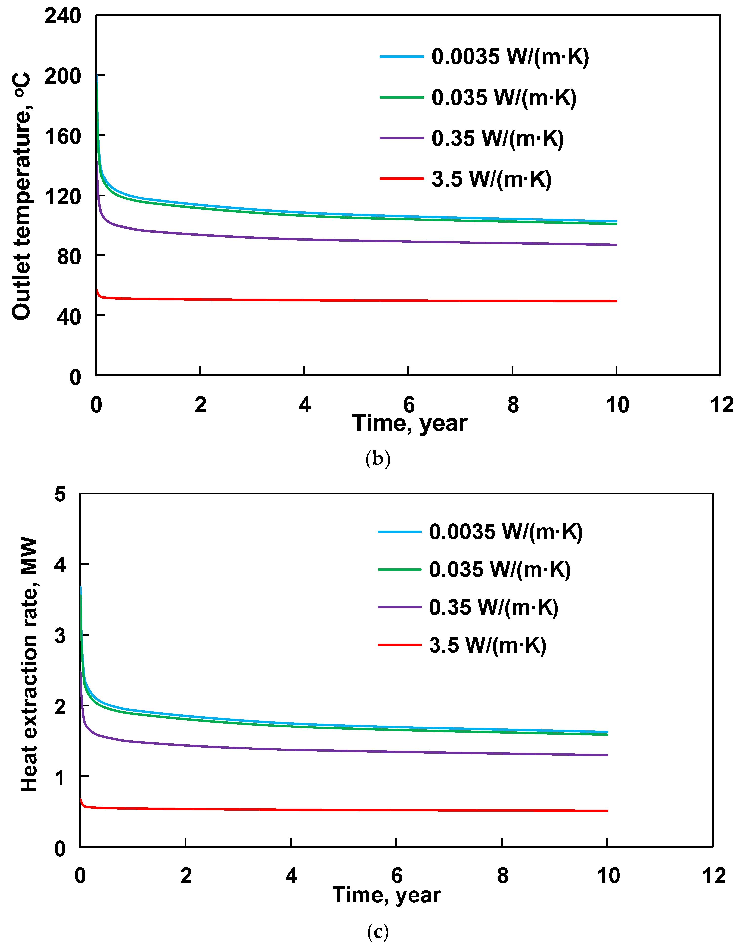
4.4. Thermal Conductivity of Tubing
The tubing thermal conductivity is an important factor to reduce water heat loss. As shown in Figure 10, when the thermal conductivity of the tubing is lower than 0.0035–0.035 W/(m·K), the temperature drop of water to the ground surface is small, indicating that heat loss in the tubing is lower. If the tubing thermal conductivity increases to 0.35 W/(m·K), the temperature of the water in the tubing will decrease sharply to 86.9 °C at the outlet from 128.9 °C at the bottom. When the tubing with thermal conductivity of 3.5 W/(m·K) is used, almost all the extracted heat is lost. In the previous study, Song et al. found that the length of the heat insulation tubing has a significant effect on the heat exchange of the circulation fluid and also found the phenomenon of “thermal short circuit” [30]. The heat exchange between the low-temperature fluid in the annulus and the high-temperature fluid in the tubing signally increases heat loss; thus the heat insulation tubing is necessary. Figure 11 is the formation temperature field around the wellbore at typical tubing thermal conductivity. Compared with heat insulation tubing, the thermal insulation performance of the oil pipe with better thermal conductivity is worse. Therefore, the heat loss ratio from the bottom of the well to the surface is larger, and the heat is not effectively extracted. Accordingly, the temperature change of the formation around the wellbore is not obvious. In summary, it is recommended to use heat insulation tubing with thermal conductivity below 0.035 W/(m·K) to prevent heat loss in the tubing.

Figure 10.
The influence of tubing thermal conductivity on heat extraction performance. (a) Wellbore temperature distribution; (b) outlet temperature; (c) heat extraction rate.
Figure 11.
Formation temperature field around the wellbore at typical tubing thermal conductivity. (a) 0.0035 W/(m·K); (b) 3.5 W/(m·K).
5. Economic Evaluation
5.1. Economic Evaluation Model
An economic evaluation model of wellbore self-circulation for heat extraction using a cluster well group was established based on the single-well economic evaluation model. The main difference is the calculation method of drilling cost. The cluster well group uses mobile drilling rigs for batch drilling. Many examples have proved that optimizing drilling operations through the accumulation of learning curves by repeated operations can significantly improve drilling efficiency and reduce construction costs [31]. To reduce the single-well cost, the cluster well group is the key factor to improve the economic feasibility of the technology using wellbore self-circulation for heat extraction in an HDR reservoir.
5.1.1. Levelized Cost of Energy (LCOE)
The levelized cost of energy (LCOE) is a common calculation method for the economic evaluation of geothermal projects. It is expressed by the ratio of cost to output power [32]. The cost of DHR geothermal development mainly includes initial investment cost, operation cost, and maintenance cost [33]. The equation for calculating LCOE is as follows:
where Atotal is the annualized total cost, USD; Ea is the average annual energy supply, kW·h; Oa is the annualized operation and maintenance cost, USD; Ia is the annualized initial investment cost, USD. Ia can be expressed as:
where i is the annual interest rate of bank loans; L is the geothermal project duration, years; Itotal is the total initial investment cost, including well construction cost and ground surface equipment cost, USD.
The average annual energy supply Ea is divided into Eah and Eap considering the two situations of heating and power generation. Under the heating condition, Eah can be expressed as:
where Q is the heat extraction rate in field conditions, kW.
There are two types of geothermal power generation, using a single working fluid (direct power generation system) and double working fluids (binary cycle power generation system). The schematic diagrams of these two power generation systems are shown in Figure 12. The single working-fluid power generation equipment is relatively simple. It requires a higher geothermal temperature and has a higher power generation efficiency. Dual working-fluid power generation equipment requires two working fluids. One fluid (e.g., water) obtains heat from the geothermal reservoirs and transfers heat to another fluid (e.g., organic working fluid). Then, the organic working fluid will expand and drive the turbine to generate electricity. The dual working-fluid power generation technology requires a low geothermal temperature and can generate electricity when the geothermal fluid temperature reaches 90 °C. Most of the temperatures from the simulation results in this article are not high. Therefore, the second type of a power generation system can be considered.
Figure 12.
Diagrams of different power generation systems. (a) Direct power generation system; (b) binary cycle power generation system.
When the water is used as the heat-carrying fluid, the outlet temperature of the self-circulation of the cluster well group may be lower than 100 °C. Therefore, the dual working-fluid power generation system was selected to calculate the power generation. Eap can be expressed as:
where hb,1 is the specific enthalpy at the inlet of the turbine, kJ/kg, and is calculated according to the fluid temperature and pressure by REFPROP software; hb,2 is the specific enthalpy at the outlet of the turbine, kJ/kg; qh is the mass flow rate of the heat-carrying fluid (water), kg/s; qo is the mass flow rate of the organic working fluid, kg/s, assuming the same as the mass flow rate of water; hb,3 is the specific enthalpy at the inlet of the booster pump, kJ/kg; hb,4 is the specific enthalpy at the outlet of the booster pump, kJ/kg; ηoi is the relative internal efficiency of steam turbine, fraction; ηme is the mechanical efficiency of steam turbine, fraction; ηpg is the efficiency of power generation, fraction; ηpump is the efficiency of the pump, fraction. The efficiency of each component in the power generation system is shown in Table 4.
Table 4.
Efficiency of each component in the power generation system.
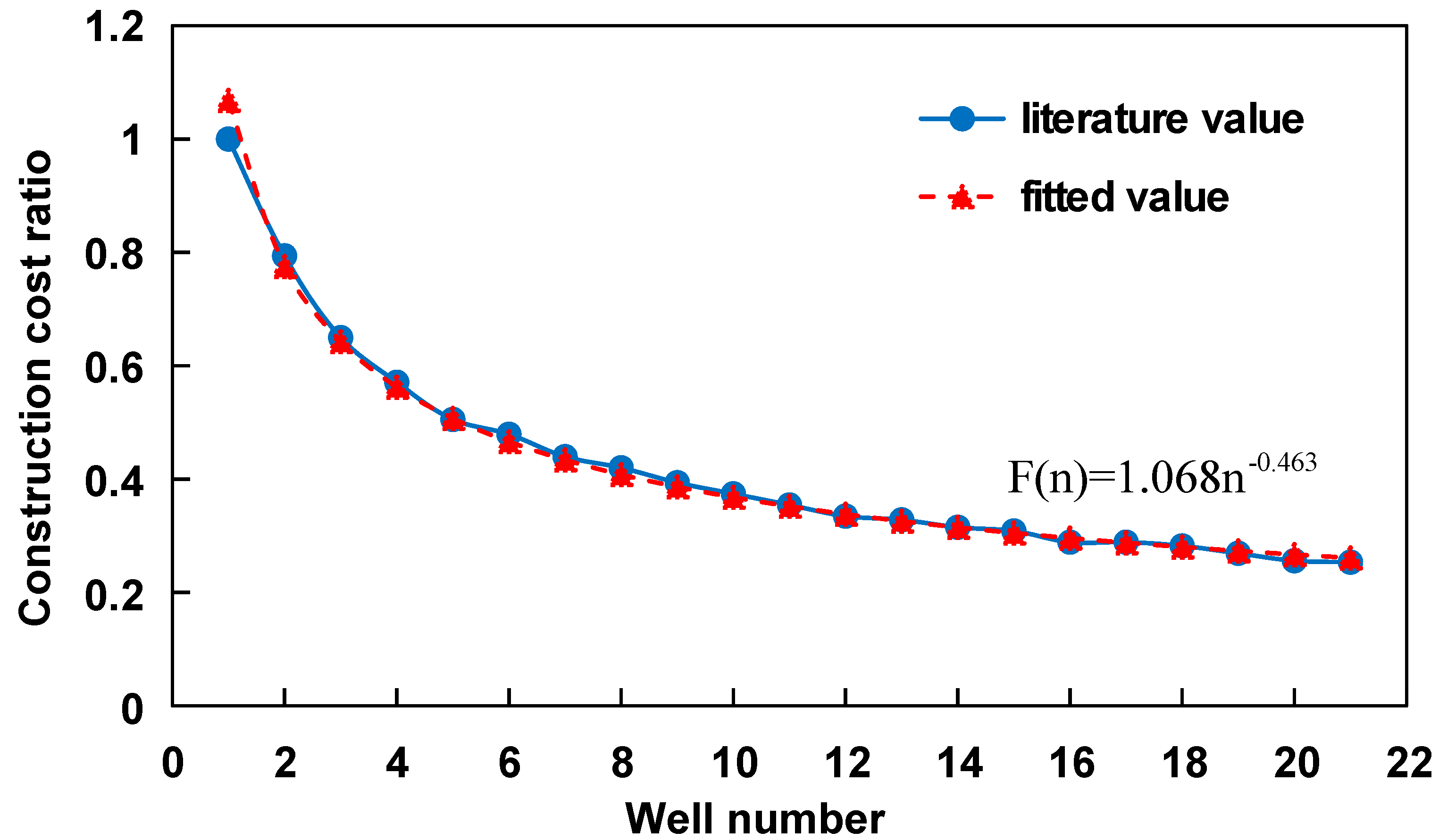
5.1.2. Well Construction Cost
- (1)
- Drilling cost
Drilling operation is a complicated and costly project. Drilling cost increases significantly with drilling depth. The single-well drilling cost can be calculated using the Fisher exponential function model [34]. The fitting relationship between drilling cost and well depth is as follows.
where y is the drilling cost, USD; x is the well depth, km.
Drilling cost usually consists of two parts: material cost and construction cost. Drilling material cost includes drilling fluid cost, drill bit cost, drilling tool cost, cement cost, cement additives cost, casing cost, casing accessories cost, oil cost, and other material costs. For the batch drilling of the cluster well group, it can be assumed that the material cost is equal to that in a single-well drilling case. However, the construction cost of batch drilling will be reduced as the number of drilled wells increases. Therefore, the drilling cost of batch drilling can be expressed as follows:
where yn is the drilling cost of the nth well in batch drilling, USD; f is the ratio of single-well material cost to drilling cost; F(n) is the ratio of the construction cost of the nth well to the construction cost of the first well.
Material cost accounts for a large proportion of drilling costs. Relevant drilling data show that material cost accounts for about 60% of the entire drilling cost on average. Therefore, the ratio of material cost to drilling cost (f) was set to 0.6. The learning curve of drilling operation can refer to the fitting curve of BP’s drilling operation in Atlantis, USA (Figure 13). The drilling operation time is equivalent to the construction cost during the drilling process, and the fitting relationship between F(n) and the well number is as follows:
Figure 13.
The learning curve of the construction cost of batch drilling in cluster well group.
According to Formulas (19) and (20), the relationship between the drilling cost and the well depth of the nth well in the cluster well group is as follows:
- (2)
- Heat insulation tubing cost
After drilling and completion, the heat insulation tubing should be installed to reduce the heat loss of the heat-carrying fluid from the bottom of the well to the wellhead. Compared with the common tubing, the cost of heat insulation tubing is higher. In this study, the price of heat insulation tubing is 70.77 USD/m [35].
- (3)
- Other costs
Other costs of well construction mainly include the initial exploration costs and the design costs of the entire project, which are set at 10% of the total drilling costs in this study.
5.1.3. Construction Cost of Ground Equipment
- (1)
- Ground power generation equipment
The ground power generation system is mainly composed of turbines, evaporators, condensers [36], and booster pumps. The initial investment cost can be expressed as follows [37]:
where Mplant is the total cost of ground power generation equipment, USD; Mevap is the evaporator cost, USD; Mcond is the condenser cost, USD; Mtu is the steam turbine cost, USD; Mpump is the booster pump cost, USD. The capital cost calculation model of each component is shown in Table 5:
Table 5.
Cost calculation model of main components of power generation system [37].
The heat exchange area in Table 5 can be calculated using the following equation [38]:
where Aevaporcond is the heat exchange area of the evaporator or condenser, m2; k is the total heat transfer coefficient, W/(m2·K); Δtm is the average temperature difference of the heat exchanger, K; Qevaporcond is the heat absorbed by the cold fluid or the heat released by the hot fluid, W; Wnet is the net power output, W; Wp is the power of the pump, W.
- (2)
- Ground heat exchange equipment
For the direct use of geothermal energy, water has the advantages of high heat extraction rate, economical availability, safety, and stability. The ground equipment includes the heat exchange station and the heating pipe network. Considering that the heating pipe network can use the coal-fired heating pipe network system that has been built in the city, the capital cost of the former is mainly considered in this study.
5.1.4. Operation and Maintenance Cost
Operation and maintenance costs mainly include personnel costs, material consumption costs, equipment maintenance costs, and other maintenance costs. In this study, the average annual operation and maintenance cost is 2% of the initial investment cost.
5.1.5. Investment Payback Time
- (1)
- Geothermal heating
Assuming that the annual interest rate of a bank loan i is 0.05, according to the above investment cost analysis and Equation (14), the calculation formula of heat extraction cost LCOEah is as follows:
where LCOEah is the annualized heat extraction cost, USD/(kW·h); ya is the annualized drilling cost, USD; Iatu is the annualized heat insulation tubing cost, USD; Iahe is the annualized heat exchange equipment cost, USD; Jah is the investment payback time of geothermal heating, years; Itu is the total cost of heat insulation tubing, USD; Ihe is the total cost of heat exchange equipment, USD.
- (2)
- Geothermal power generation
Assuming that the annual interest rate of bank loan i is 0.05, the calculation formula of power generation cost LCOEap is as follows:
where LCOEap is the annualized power generation cost, USD/(kW·h); Maplant is the annualized cost of ground power generation equipment, USD; Jap is the investment payback time of geothermal power generation, years.
After the project scheme is determined, the levelized cost (LCOEah or LCOEap) of the expected payback period (Jah or Jap) can be calculated according to the above formula. If the levelized cost in the expected payback time is lower than the price of geothermal heating or power generation, the project scheme is reasonable.
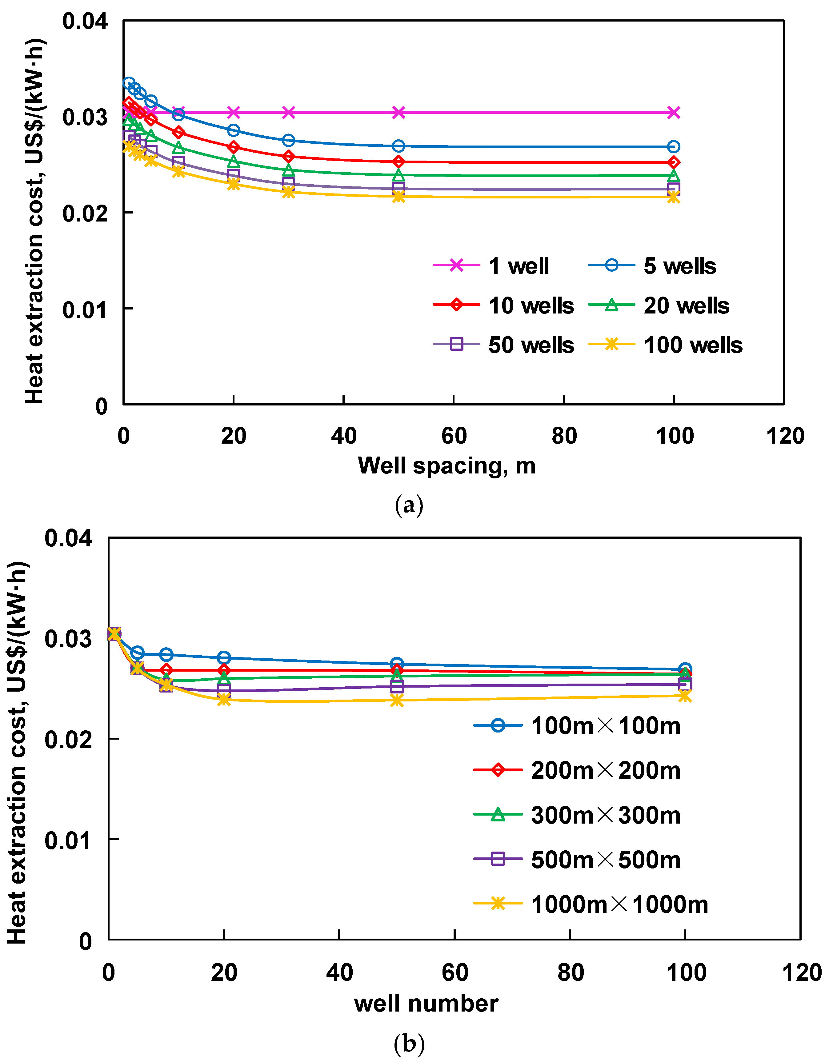
5.2. Heat Extraction Cost of Cluster Well Group
To evaluate the economic benefits of single-well self-circulation for heat extraction by the cluster well group, water is selected as the heat-carrying fluid, and a horizontal section is used. The length of the horizontal section is 2000 m. The injection rate is 5 kg/s, and the drilling cost of the horizontal section is twice that of the vertical section [39]. The operating time of the heating system is 30 years, and the bank loan interest rate is 5%. The calculation of heat extraction cost considers the two situations of unlimited well site area and limited well site area.
Figure 14 shows the unit heat extraction cost with different well spacing and well number. The number of wells is constant in Figure 14a, and the unit heat extraction cost decreases with the increase in the well spacing. However, the cost of heat extraction tends to be stable when the well spacing exceeds 30 m. In addition, increasing the number of wells in an unlimited well site area can also reduce the cost of drilling and reduce the cost per unit of heat extraction. Compared with a single well, the unit heat extraction cost can be reduced from 0.0303 USD/(kW·h) to 0.0229 USD/(kW·h), and the reduction is 24.3%. In Figure 14b, when the area of the well site is less than 200 m × 200 m, the cost of heat extraction decreases with the increase in the well number. If the area of the well site expands, the heat extraction cost first decreases and then slowly increases with the increase in the well number. It indicates that there is an optimal well number or well spacing when the well site area is constant. Table 6 shows the heat extraction costs of different expected investment payback times in typical well spacing and well numbers. It can be seen from the table that the cost decreases with the increase in the expected payback time. At present, the heating cost is about 0.0308 USD/(kW·h) in China; thus this technology has good economic benefits for heating.
Figure 14.
Heat extraction cost of cluster wells with different spacing and well numbers. (a) Unlimited well site area; (b) limited well site area.
Table 6.
Heat extraction costs of different expected investment payback times (USD/(kW·h)).
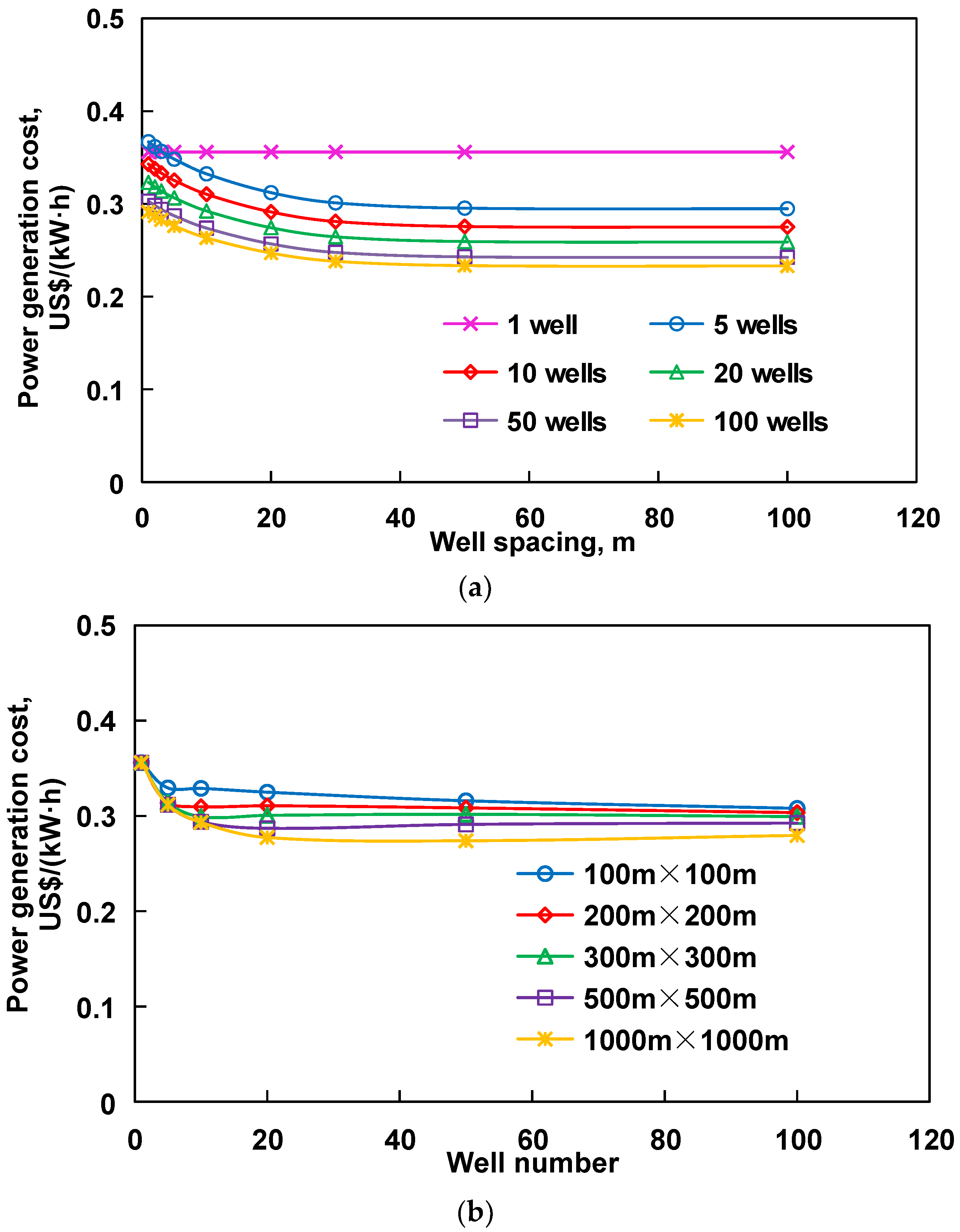
5.3. Power Generation Cost of Cluster Well Group
Figure 15 shows the unit power generation cost with different well spacing and well number. The thermal short-circuit effect of small well spacing is serious, and thus the heat extraction rate is small. The well spacing of five heat extraction wells is increased from 1 m to 50 m, and the unit power generation cost is reduced from 0.385 USD/(kW·h) to 0.311 USD/(kW·h). Compared with a single well, the unit power generation cost can be reduced from 0.355 USD/(kW·h) to 0.265 USD/(kW·h), and the reduction is 25.5% (30 m well spacing, 50 heat extraction wells). Table 7 shows the power generation costs of different investment payback times in typical well spacing and well numbers. It can be seen that the cost of power generation decreases with the increase in the expected payback time. At present, the cost of various clean power generation in China is 0.062 USD/(kW·h) for hydropower, 0.138 USD/(kW·h) for nuclear power, and 0.077 USD/(kW·h) for wind power. According to the above analysis, the unit cost of power generation using water as the heat-carrying medium is higher. In 2019, Wang et al. compared the cost of water and isobutane as the heat-carrying fluid for geothermal power generation, and the results show that isobutane has a lower power generation cost than water, with the lowest cost being only 0.187 USD/(kW·h) [23]. To sum up, using an organic medium as the heat-carrying fluid has a lower heat extraction rate, but it is more economical for power generation. Based on the above analysis, we can consider retrofitting the existing wells, using circulation organic fluids and extending the project time appropriately to save construction costs and reduce power generation costs.
Figure 15.
Power generation cost of cluster wells with different spacing and well numbers. (a) Unlimited well site area; (b) limited well site area.
Table 7.
Power generation costs of different expected investment payback times (USD/(kW·h)).
6. Conclusions
- (1)
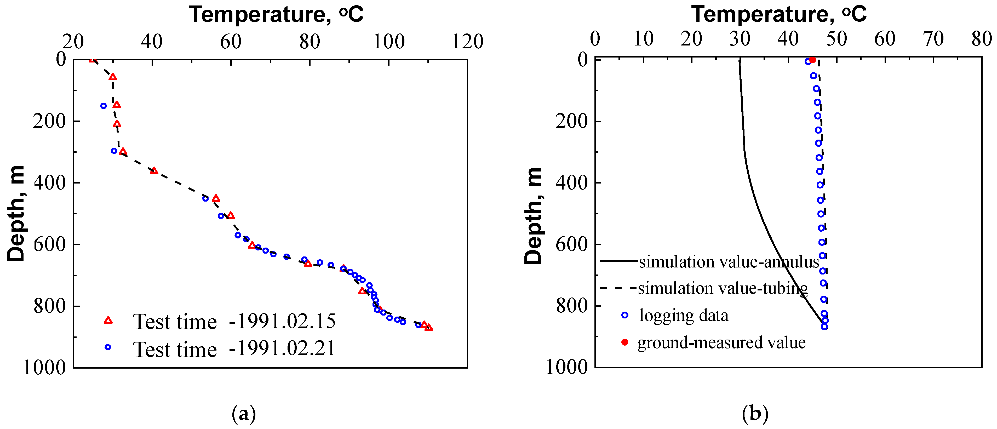
- The use of clustered horizontal well groups for geothermal production can enhance the heat extraction capacity of the self-circulating wellbore and reduce the drilling cost per well. A numerical simulation model of the self-circulation wellbore for heat extraction in hot dry rocks using cluster horizontal wells was established based on the mathematical model. The reliability of the model has been validated by fitting the published geothermal test data.
- (2)
- With the increase in water injection rate, the heat extraction rate of cluster wells will increase first and tend to be stable. The water injection rate is stable at 432 m3/d/well; the outlet temperature and the heat extraction rate per well after 10 years are 100.9 °C and 1.59 MW, respectively. When the thermal conductivity of formation increases from 2 to 3.5 W/(m·K), the heat extraction rate will increase 1.45 times. The thermal conductivity of tubing has important effects on the heat extraction rate. The installation of heat insulation tubing is necessary. The reasonable well spacing and well number should be determined according to the field conditions.
- (3)
- The use of a cluster well group can reduce the unit costs of heat extraction and power generation. Compared with a single well, the unit heat extraction cost can be reduced by 24.3% from 0.0303 USD/(kW·h) to 0.0229 USD/(kW·h), and the unit power generation cost can be reduced by 25.5% from 0.355 USD/(kW·h) to 0.265 USD/(kW·h).
- (4)
- If cluster horizontal wells are used for heat extraction on site, it is recommended to prioritize the location of areas with better formation thermal properties, and the inflection point of injection rate can be determined as the basis for the working system. In addition, the thermal conductivity of the tubing should be less than 0.035 W/(m·K) to reduce heat loss. In addition, the well spacing of cluster wells is recommended to be larger than 50 m to avoid thermal short-circuiting between wells. Geothermal power generation is feasible, but the cost of power generation can be further reduced by retrofitting existing wellbores and optimizing the heat-carrying fluids.
Author Contributions
Conceptualization, Z.Z., G.Q., H.C., L.Y., S.G., R.W., and L.Z.; methodology, Z.Z., G.Q., H.C., L.Y., S.G., R.W., and L.Z.; validation, Z.Z., G.Q., H.C., L.Y., S.G., R.W., and L.Z.; formal analysis, Z.Z., G.Q., H.C., and L.Y.; investigation, S.G.; resources, L.Z.; data curation, Z.Z., G.Q., H.C., L.Y., S.G., R.W., and L.Z.; writing—original draft preparation, Z.Z., G.Q., H.C., L.Y., S.G., R.W., and L.Z.; writing—review and editing, Z.Z., G.Q., and L.Y.; project administration, R.W. All authors have read and agreed to the published version of the manuscript.
Funding
This research was funded by the Basic Research Program Project of Qinghai Province, grant number No. 2020-ZJ-758.
Institutional Review Board Statement
Not applicable.
Informed Consent Statement
Not applicable.
Data Availability Statement
The data presented in this study are available on request from the corresponding author.
Acknowledgments
We appreciate the reviewers and editors for their constructive comments to make sure the paper is of high quality.
Conflicts of Interest
The authors declare no conflict of interest.
Abbreviations
| Nomenclature | |
| q | mass flow, kg/s |
| l | length of the well section, m |
| r | radius, m |
| ρ | density, kg/m3 |
| v | flow rate, m/s |
| g | acceleration of gravity, m/s2 |
| f | hydraulic friction coefficient |
| d | diameter, m |
| t | time, s |
| T | temperature, °C |
| Q | heat flux, W |
| c | specific heat capacity, J/(kg·K) |
| h | convective heat transfer coefficient, W/(m2·K) |
| λ | thermal conductivity, W/(m·K) |
| G | geothermal gradient, °C/m |
| z | vertical depth, m |
| A | annualized cost, USD; |
| E | energy supply, kW·h |
| O | operation and maintenance cost, USD |
| I | initial investment cost, USD |
| i | annual interest rate of bank loans |
| Qe | heat extraction rate under field conditions, kW |
| η | efficiency, fraction |
| y | drilling cost, USD |
| x | well depth, km |
| F(n) | the ratio of the construction cost of the nth well to the construction cost of the first well |
| M | cost, USD |
| A | heat exchange area, m2 |
| W | power, kW |
| k | total heat transfer coefficient, W/(m2·K) |
| J | investment payback time, years |
| Subscripts | |
| h | heat-carrying fluid |
| tu | tubing |
| ca | casing |
| ht | heat-carrying fluid in the tubing |
| ha | heat-carrying fluid in the annulus |
| tu1 | inner wall of the tubing |
| tu2 | outer wall of the tubing |
| ca1 | inner wall of the casing |
| ca2 | outer wall of the casing |
| F, tu | per unit length of the tubing |
| F, an | per unit length of the annulus |
| ca, ce | casing and cement sheath |
| ce | cement sheath |
| ce2 | outer wall of the cement sheath |
| r | formation |
| ce, r | cement sheath and formation |
| s | surface |
| b | boundary of formation |
| const | constant |
| a | annualized |
| to | total |
| ah | considering heating |
| ap | considering power generation |
| o | organic working fluid |
| b, 1 | inlet of the turbine |
| b, 2 | outlet of the turbine |
| oi | internal of steam turbine |
| me | mechanical |
| pg | power generation |
| pump | pump |
| plant | all the ground power generation equipment |
| evap | evaporator |
| cond | condenser |
| net | net |
| he | heat exchanger |
| n | the nth well |
| atu | annualized heat insulation tubing |
| ahe | annualized heat exchange equipment |
| he | heat exchange equipment |
| Superscripts | |
| L | geothermal project duration |
| Abbreviations | |
| LCOE | levelized cost of energy |
References
- Lu, C.; Wang, G. Current status and prospect of hot dry rock research. Sci. Technol. Rev. 2015, 33, 13–21, (In Chinese with English Abstract). [Google Scholar]
- Wang, J.; Hu, S.; Pang, Z.; He, L.; Zhao, P.; Zhu, C.; Rao, S.; Tang, X.; Kong, Y.; Luo, L.; et al. Estimate of geothermal resources potential for hot dry rock in the continental area of China. Sci. Technol. Rev. 2012, 30, 25–31, (In Chinese with English Abstract). [Google Scholar]
- Zeng, Y. Technical Progress and Thinking for development of hot dry rock (HDR) geothermal resources. Pet. Drill. Tech. 2015, 43, 1–7, (In Chinese with English Abstract). [Google Scholar]
- Liao, Z.; Wan, T.; Zhang, Z. The enhanced geothermal system (EGS): Huge capacity and difficult exploitation. Earth Sci. Front. 2015, 22, 335–344, (In Chinese with English Abstract). [Google Scholar]
- Sanyal, S.K.; Butler, S.J. An analysis of power generation prospects from enhanced geothermal systems. Geotherm. Resour. Counc. 2005, 29, 131–138. [Google Scholar]
- Wang, X.; Wu, N.; Su, Z.; Zeng, Y. Progress of the enhanced geothermal systems (EGS) development technology. Prog. Geophys. 2012, 27, 355–362, (In Chinese with English Abstract). [Google Scholar]
- Lu, S. A global review of enhanced geothermal system (EGS). Renew. Sustain. Energy Rev. 2018, 82, 2902–2921. [Google Scholar] [CrossRef]
- Brown, D.; Duteaux, R.; Kruger, P.; Swenson, D.; Yamaguchi, T. Fluid circulation and heat extraction from engineered geothermal reservoirs. Geothermics 1999, 28, 553–572. [Google Scholar] [CrossRef]
- Pruess, K. Enhanced geothermal systems (EGS) using CO2 as working fluid—A novel approach for generating renewable energy with simultaneous sequestration of carbon. Geothermics 2006, 35, 351–367. [Google Scholar] [CrossRef] [Green Version]
- Zhang, L.; Ezekiel, J.; Li, D.; Pei, J.; Ren, S. Potential assessment of CO2 injection for heat mining and geological storage in geothermal reservoirs of China. Appl. Energy 2014, 122, 237–246. [Google Scholar] [CrossRef]
- Spitler, J.D.; Javed, S.; Ramstad, R.K. Natural convection in groundwater-filled boreholes used as ground heat exchangers. Appl. Energy 2016, 164, 352–365. [Google Scholar] [CrossRef]
- Kujawa, T.; Władysław, N. Utilization of existing deep geological wells for acquisitions of geothermal energy. Energy 2006, 31, 650–664. [Google Scholar] [CrossRef]
- Wood, C.J.; Liu, H.; Saffa, B.R. Comparative performance of ‘U-tube’ and ‘coaxial’ loop designs for use with a ground source heat pump. Appl. Therm. Eng. 2012, 37, 190–195. [Google Scholar] [CrossRef]
- Beier, R.A.; Acuña, J.; Mogensen, P.; Palm, B. Borehole resistance and vertical temperature profiles in coaxial borehole heat exchangers. Appl. Energy 2013, 102, 665–675. [Google Scholar] [CrossRef]
- Holmberg, H.; Acuña, J.; Næss, E.; Sønju, O.S. Thermal evaluation of coaxial deep borehole heat exchangers. Renew. Energy 2016, 97, 65–76. [Google Scholar] [CrossRef]
- Cui, G.; Ren, S.; Zhang, L.; Ezekiel, J.; Enechukwu, C.; Wang, Y.; Zhang, R. Geothermal exploitation from hot dry rocks via recycling heat transmission fluid in a horizontal well. Energy 2017, 128, 366–377. [Google Scholar] [CrossRef]
- Gordon, D.; Bolisetti, T.; Ting, D.S.; Reitsma, S. Experimental and analytical investigation on pipe sizes for a coaxial borehole heat exchanger. Renew. Energy 2018, 115, 946–953. [Google Scholar] [CrossRef]
- Dai, C.; Li, J.; Shi, Y.; Zheng, L.; Lei, H. An experiment on heat extraction from a deep geothermal well using a downhole coaxial open loop design. Appl. Energy 2019, 252, 113–121. [Google Scholar] [CrossRef]
- Yildirim, N.; Parmanto, S.; Akkurt, G.G. Thermodynamic assessment of downhole heat exchangers for geothermal power generation. Renew. Energy 2019, 141, 1080–1091. [Google Scholar] [CrossRef]
- Wang, G.; Song, X.; Shi, Y.; Yang, R.; Yulong, F.; Zheng, R.; Li, J. Heat extraction analysis of a novel multilateral-well coaxial closed-loop geothermal system. Renew. Energy 2021, 163, 974–986. [Google Scholar] [CrossRef]
- Pokhrel, S.; Sasmito, A.P.; Sainoki, A.; Tosha, T.; Tanaka, T.; Nagai, C.; Ghoreishi-Madiseh, S.A. Field-scale experimental and numerical analysis of a downhole coaxial heat exchanger for geothermal energy production. Renew. Energy 2022, 182, 521–535. [Google Scholar] [CrossRef]
- Alimonti, C.; Soldo, E. Study of geothermal power generation from a very deep oil well with a wellbore heat exchanger. Renew. Energy 2016, 86, 292–301. [Google Scholar] [CrossRef]
- Wang, Y.; Zhang, L.; Cui, G.; Kang, J.; Ren, S. Geothermal development and power generation by circulating water and isobutane via a closed-loop horizontal well from hot dry rocks. Renew. Energy 2019, 136, 909–922. [Google Scholar] [CrossRef]
- Kurnia, J.C.; Putra, Z.A.; Muraza, O.; Ghoreishi-Madiseh, S.A.; Sasmito, A.P. Numerical evaluation, process design and techno-economic analysis of geothermal energy extraction from abandoned oil wells in Malaysia. Renew. Energy 2021, 175, 868–879. [Google Scholar] [CrossRef]
- Zeng, J. Research on Temperature and Pressure Field Model of Supercritical Carbon Dioxide Fracturing Wellbore. Master’s Thesis, Southwest Petroleum University, Chengdu, China, 2014. (In Chinese with English Abstract). [Google Scholar]
- Guo, J.; Zeng, J. A coupling model for wellbore transient temperature and pressure of fracturing with supercritical carbon dioxide. Acta Pet. Sin. 2015, 36, 203–209, (In Chinese with English Abstract). [Google Scholar]
- Cheng, W.; Li, T.; Nian, Y.; Xie, K. An analysis of insulation of abandoned oil wells reused for geothermal power generation. Energy Procedia 2014, 61, 607–610. [Google Scholar] [CrossRef] [Green Version]
- Wang, Y. Geothermal Exploitation via Circulating Fluid within a Closed-Loop Horizontal Well from Hot Dry Rocks. Master’s Thesis, China University of Petroleum (East China), Qingdao, China, 2019. (In Chinese with English Abstract). [Google Scholar]
- Morita, K.; Bollmeier, W.S. Mizogami, H. Analysis of the results from the downhole coaxial heat exchanger (DCHE) experiment in Hawaii. Geotherm. Resour. Counc. Trans. 1992, 16, 17–23. [Google Scholar]
- Song, X.; Wang, G.; Shi, Y.; Li, R.; Xu, Z.; Zheng, R.; Wang, Y.; Li, J. Numerical analysis of heat extraction performance of a deep coaxial borehole heat exchanger geothermal system. Energy 2018, 164, 1298–1310. [Google Scholar] [CrossRef]
- Han, L.; Xiang, X.; Yan, R.; Du, W.; Xiong, S.; Du, J. Low-cost batch drilling technology used to drill cluster wells. Drill. Prod. Technol. 2012, 35, 5–8, (In Chinese with English Abstract). [Google Scholar]
- Glassley, W.E. Geothermal Energy: Renewable Energy and the Environment; CRC Press: Boca Raton, FL, USA, 2014. [Google Scholar]
- Zou, Y. Drilling Cost Analysis of Oil Field Production Capacity Construction. Doctoral Dissertation, Southwest Petroleum University, Chengdu, China, 2013. (In Chinese with English Abstract). [Google Scholar]
- Fan, M.; Li, Z.; Feng, L. Cost forecast model study on oil and gas well operation. Nat. Gas Ind. 2007, 27, 134–136, (In Chinese with English Abstract). [Google Scholar]
- Li, J.; Wang, L.; Shi, S.; Li, J. Economic analysis of injection and production of vertical well with thermal insulation tubing in super heavy oil reservoir: A case study of Fengcheng Oilfield. Pet. Geol. Eng. 2014, 28, 137–140, (In Chinese with English Abstract). [Google Scholar]
- Strušnik, D.; Golob, M.; Avsec, J. Effect of non-condensable gas on heat transfer in steam turbine condenser and modelling of ejector pump system by controlling the gas extraction rate through extraction tubes. Energy Convers. Manag. 2016, 126, 228–246. [Google Scholar] [CrossRef]
- Yao, S.; Zhang, Y.; Yu, X. Thermo-economic analysis of a novel power generation system integrating a natural gas expansion plant with a geothermal ORC in Tianjin, China. Energy 2018, 164, 602–614. [Google Scholar] [CrossRef]
- Zhang, J.; Chang, H. Heat Transfer; Science Press: Beijing, China, 2015; (In Chinese with English Abstract). [Google Scholar]
- Joshi, S.D. Cost/Benefits of horizontal wells. In Proceedings of the SPE Western Regional/AAPG Pacific Section Joint Meeting, Long Beach, CA, USA, 19–24 May 2003. [Google Scholar]
Publisher’s Note: MDPI stays neutral with regard to jurisdictional claims in published maps and institutional affiliations. |
© 2022 by the authors. Licensee MDPI, Basel, Switzerland. This article is an open access article distributed under the terms and conditions of the Creative Commons Attribution (CC BY) license (https://creativecommons.org/licenses/by/4.0/).