Islanding Fault Detection in Microgrids—A Survey


1
Department of Electrical and Systems Engineering, Washington University in St. Louis, St. Louis, MO 63130-4899, USA
2
School of Electrical and Computer Engineering, College of Engineering, University of Tehran, Tehran 14395-515, Iran
*
Author to whom correspondence should be addressed.
Energies 2020, 13(13), 3479; https://doi.org/10.3390/en13133479
Submission received: 11 June 2020
/
Revised: 25 June 2020
/
Accepted: 2 July 2020
/
Published: 6 July 2020
(This article belongs to the Special Issue Microgrids and Fault-Tolerant Control)
Abstract
:This paper provides an overview of islanding fault detection in microgrids. Islanding fault is a condition in which the microgrid gets disconnected from the microgrid unintentionally due to any fault in the utility grid. This paper surveys the extensive literature concerning the development of islanding fault detection techniques which can be classified into remote and local techniques, where the local techniques can be further classified as passive, active, and hybrid. Various detection methods in each class are studied, and advantages and disadvantages of each method are discussed. A comprehensive list of references is used to conduct this survey, and opportunities and directions for future research are highlighted.

1. Introduction
Microgrids are defined as a cluster of loads, distributed energy generation units, and storage devices. Microgrids can be either connected to the utility grid or disconnected from it. When a microgrid is connected to the utility grid, the microgrid can inject power to the utility grid when there is a surplus power, and in the case of power shortage, the utility grid can help the microgrid to supply the demanded power. When the microgrid is disconnected from the microgrid, the generation units should continue supplying the loads by themselves.
Microgrids are the most promising solution for the current high rate of consumption of nuclear and fossil fuels, and for the need to reduce pollutant emission in electricity generation field. However, numerous problems should be addressed before their widespread usage in the power networks. These problems include frequency stabilization (e.g., model predictive control [1], passivity-based approach [2], and Lyapunov-based approach [3]), voltage stabilization (e.g., PI controller [4], fuzzy logic [5], droop control [6], and consensus-based approach [7]), robustness against uncertainties (e.g., optimization-based approach [8], load shedding-based approach [9], neural networks [10], and three phase improved magnitude phase locked loop [11]), and tolerance toward faults (e.g., reconfiguration-based approach [12], model predictive control [13], optimization-based approach [14], model-based techniques [15], and a consensus-based approach [16]).
Faults can happen either in the microgrid components or in the utility grid. Faults in the microgrid components usually change the operating points of the generation units and storage devices to supply the demanded power by the loads, for example, lubricant system fault in wind system [17], sensor fault in the wind system [18], shading fault in the solar system [19], inverter fault in the solar system [20], battery fault [21], ground fault [22], and converter switching faults [23]. See Reference [24] and references therein for a comprehensive study on the subject. However, faults on the grid side can cause a sequence of switching events which can eventually disconnect the microgrid from the utility grid [25].
Disconnection from the utility grid is called islanding, which can be either intentional (due to scheduled maintenance [26] or economical/management constraints [27]) or unintentional (due to faults or other uncertainties in the utility grid [28]). The latter case is called islanding fault, which poses the following drawbacks—(1) It is a hazard for personnel, as they may consider the systems as inactive while the generation units are feeding power to the loads [29]; (2) The voltage and frequency may not be maintained at a standard acceptable level [30]; and (3) Circuit reclosers reconnect the disconnected microgrid to the utility grid when out of phase [31]. Therefore, quick and accurate detection of the islanding fault is a very important issue that should be addressed properly. It is noteworthy that the IEEE Std 1547 [32], IEEE Std 929 [33], and IEC Std 61727 [34] specify that the islanding fault should be detected within 2 s.
Islanding fault detection techniques can be classified into two basic types [35]: remote and local techniques, where the local techniques can be further categorized as passive, active, and hybrid (see Figure 1). The core idea of all techniques is to monitor the microgrid parameters, and detect the occurrence of the islanding fault based on the changes in these parameters. It is reported in Reference [36] that from 1988 to 2012, 5% of the proposed methods was remote, 20% was passive, 41% was active, and 34% was hybrid.
In this paper, we survey several basic and more recent islanding fault detection methods. In particular, this paper has two main objectives—(1) to summarize research efforts related to the islanding fault detection in microgrids, including both remote and local techniques, and (2) to discuss potential research directions addressing some of the weaknesses of each technique. This paper is different from the existing ones in the literature, and our contributions are two-fold. First, instead of concentrating on one technique, we conduct a comprehensive survey focusing on both remote and local (including passive, active, and hybrid) techniques. Second, we discuss more recent and promising research outcomes in each covered research area. We believe that this paper provides sufficient breadth and depth on the subject, specifically for researchers who are new to this field.
The rest of this paper is organized in the following order. Section 2 surveys three common remote techniques; transfer trip scheme method in Section 2.1, power line carrier communication in Section 2.2, and system state monitoring in Section 2.3. Section 3 studies local techniques. In particular, nine passive methods are described in Section 3.1, where advantages and disadvantages of each method are discussed. In Section 3.2, some common active methods are studied. The pros and cons of active methods in comparison with passive methods are highlighted. Hybrid techniques are surveyed in Section 3.3. This section describes the main philosophy of the hybrid methods, their connection with passive and active methods, and their strengths and weaknesses. Finally, Section 4 provides concluding remarks.
2. Remote Techniques
Communication between the utility grid and the microgrid is the basis of remote techniques. More precisely, the main idea in the remote techniques is to share the information between the utility grid and the microgrid through a communication channel, and use signal processing techniques to detect the islanding fault. Three approaches along this line are surveyed below.
2.1. Transfer Trip Scheme
The transfer trip scheme (a.k.a. switch state monitoring [37] and Intertripping [38]) is developed based on monitoring the status of all the circuit breakers and reclosers. To do so, the transfer trip scheme needs to be incorporated with the Supervisory Control and Data Acquisition (SCADA) system to monitor the operation of all switches [39]. When a disconnection is detected in the microgrid, the transfer trip system can determine which area is disconnected from the utility grid, and sends appropriate commands to the corresponding control units to run the disconnected areas in islanding mode. A schematic of this method is depicted in Figure 2.
The transfer trip scheme has a negligible non-detection zone and usually provides a fast islanding fault detection. However, implementation cost and complexity of this method is considerably high, as it requires a thorough interaction between the utility grid and the microgrid.
2.2. Power Line Carrier Communication
This method (a.k.a. Power Line Signaling [40]) includes two types of devices: (1) a transmitter that uses the the power line to send a low-energy communication signal, and (2) receivers that are installed at the microgrid side at appropriate points. In this method, the transmitter broadcasts a signal toward the microgrid side, which is called anti-islanding signal. If any receiver does not sense the signal (caused by the opening of the circuit breakers) for certain duration, it is considered as an islanding fault in the corresponding area. A schematic of the power line carrier communication method is depicted in Figure 3.
As suggested in Reference [41], the signal should be a low-frequency signal (at or below 500 [Hz]), as high-frequency signals are strongly attenuated by the inductors in distribution transformers. A possible way to generate such signal is to use the waveform distortion technique [40]. The suggested pattern is to broadcast the signal for every four cycles, where the islanding fault is detected if the receiver does not sense the signal for two/three cycles.
The power line carrier communication method is reliable, has almost zero non-detection zone, and works effectively in microgrids with multiple areas. This method provides a fast detection, and has no impact on the power quality. However, the power line carrier communication method can be very expensive to implement, specially on small-scale microgrids.
2.3. System State Monitoring
This method, which is generally considered as a function of the SCADA system (hence, also called SCADA-based method [42]), utilizes microgrid parameters to detect the islanding fault. The parameters usually used in this method are voltage and frequency [43]. A schematic of the system state monitoring method is depicted in Figure 4, where dashed lines represent communication channels.
The system state monitoring method has been tested on microgrids with Photovoltaic (PV) systems as the generation units [44,45]. However, its applicability in microgrids with different types of generation units is still unknown and needs more investigation.
The key point of the system state monitoring method is that the parameters must be detectable from the disconnected areas, meaning that the microgrid must be properly instrumented, and adequately equipped with communication devices. Hence, this method can be a cumbersome process (particularly for large-scale microgrids), and can have a very high cost of implementation.
3. Local Techniques
The main idea of the local techniques is to monitor the parameters on the microgrid side. Local techniques can be classified into three types—(1) passive techniques, (2) active techniques, and (3) hybrid techniques. This section studies these types separately. For each type, recent and most promising methods presented in the literature will be surveyed, and advantages and disadvantages of each method will be discussed.
3.1. Passive Techniques
Passive techniques monitor parameters such as frequency, voltage, and harmonics in the microgrid, and compare them with predefined threshold values in order to detect the islanding fault. More precisely, passive techniques take advantage of the fact that some of the microgrid parameters vary greatly when the microgrid gets disconnected from the utility grid. In this section, the philosophy of nine very common passive techniques will be explained, and their merits and demerits will be discussed.
3.1.1. Rate of Change of Output Power
Consider the microgrid shown in Figure 5, where (expressed in [W]) is the injected power from the utility grid to the microgrid, (expressed in [W]), (expressed in [Var]), and (expressed in [A]) are respectively the active power, the reactive power, and the current generated by the generation units in the microgrid, (expressed in [W]), (expressed in [Var]), and (expressed in [A]) are respectively the active power, the reactive power, and the current demanded by the loads, V (expressed in [V]) is the voltage at the Point of Common Coupling (PCC), and f (expressed in [Hz]) is the frequency at PCC.
Suppose that the utility grid and the generation units are modelled by idealized generators of capacity and (expressed in [MW]) and with inertia constraints and (expressed in [MJ/MVA]), respectively. Let (expressed in [W]) be a change in the load. When the microgrid is connected to the utility grid, the load change will change the output power of the generation units as follows [38]
which means that . When the microgrid is disconnected from the utility grid, any load changes will have a direct effect on the generation units, that is, . Thus, since has a high value, the rate of change of output power (denoted by ) once the microgrid is isolated will be much greater than that of connected microgrid [36].
According to the mentioned discussion, the islanding fault can be detected by monitoring the change of the generated power by the generation units over a finite horizon. More precisely, assuming a horizon with length (expressed in [s]), the criterion for islanding fault detection at time t is (in this paper, time is discrete)
where (expressed in [W/s]) is the threshold value, usually chosen for a specific false detection rate. Note that should be less than the operating time of six cycles [39].
As discussed in Reference [46], islanding fault detection based on the rate of change of output power is more effective in the presence of unbalanced load rather than balanced load. This method provides a fast islanding fault detection, and is not affected by the small power mismatches between the generated and demanded powers [42]. However, it has a high error detection rate. The detection time of this method is 24–26 [ms], and this method has a small non-detection zone [47]. An operating point inside the associated non-detection zone of this method corresponds to the case where there is no sufficient available power to compensate the load change (e.g., the generation units were already operating at their maximum power point before disconnection). In this case, the change in the generated power by the generation units will be zero (i.e., ), meaning that the islanding fault cannot be detected by using this method.
3.1.2. Rate of Change of Frequency
This principle of this method is very similar to the method discussed in Section 3.1.1, but it detects the islanding fault based on the rate of change of frequency at PCC [48,49]. Consider the microgrid shown in Figure 5, and let be the load change. When the microgrid is connected to the utility grid, the rate of change of frequency can be computed as follows [50]
where f is the frequency at PCC. Now, suppose that the microgrid is isolated form the utility grid. In this case, the rate of change of frequency in the presence of the load change is
Since the denominator of (3) is greater than that of (4), it can be concluded that, in the presence of an equal load change, the rate of change of frequency in an isolated microgrid will be greater that that of a connected microgrid. This means that the islanding fault can be detected at time t by monitoring the change of frequency over a finite horizon, as follows
where (expressed in [s]) is the length of the detection horizon, and (expressed in [Hz/s]) is the threshold value. Note that should not exceed four to six cycles [42]. For small- and medium-sized microgrids, it is suggested in Reference [38] that should be 0.3 to 0.7 [s], and should be 0.3 [Hz/s].
Islanding fault detection based on the rate of change of frequency is effective, as if it fails to detect the islanding fault at the instant of the occurrence, any subsequent load change will generally lead to detection. This method works better when there is a large load change in the microgrid. However, its performance is not good when the capacity of the generation units matches the demanded load [51]. Islanding fault detection based on the rate of change of frequency cannot reliably discriminate between frequency changes due to islanding fault and due to other faults/disturbances [52]. The detection time of this method is around 24 [ms], and this method has a small non-detection zone [47].
3.1.3. Rate of Change of Frequency over Output Power
This method is a combination of the methods presented in Section 3.1.1 and Section 3.1.2, and enjoys the advantages of both. When the microgrid is connected to the utility grid, according to (1) and (3), the load change implies that
When the microgrid is isolated from the utility grid, according to (4) and since , the rate of change of frequency over output power in the presence of the load change is
According to (6) and (7), and since , it can be concluded that monitoring the change of frequency over change of output power of the generation units can be used as a criterion to detect the islanding fault occurrence. Thus, the islanding fault can be detected at time t through the following measure
where (expressed in [s]) is the length of the detection horizon, and (expressed in [Hz/W·s]) is the threshold value.
It is shown in Reference [53] that this method is effective even in the presence of small load changes. The detection time of this method is around 100 [ms], and this method has a very low error detection rate [47]. Also, the non-detection zone of this method is much smaller than that of the methods presented in Section 3.1.1 and Section 3.1.2.
3.1.4. Change of Impedance
Source impedance of the utility grid is considerably smaller than that of generation units in the microgrid. Thus, by continuously monitoring the source impedance, it is possible to detect the islanding fault [54]. More precisely, the source impedance of a connected microgrid will be lower than that of an isolated microgrid. This difference in the source impedance can be used as a criterion to detect the islanding fault.
One possible way to measure the source impedance is to impose a near short-circuit condition late in the main half-cycle and measure the the resulting current. For this purpose, a structure is proposed in Reference [55]. The resistor is very small (∼ 2 []), and the switch allows current late in a very short interval of the half-cycle (from 178° until the time that the current begins to reverse). See Figure 6 for more details.
When the microgrid is connected to the utility grid, since the source impedance is a parallel combination of the impedance of the utility grid and the generation units, the current (expressed in [A]) will have a high amplitude. While, when the microgrid is operating in islanding condition, the current will have a low amplitude, as the source impedance is equal to the impedance of the generation units which has a large value. Therefore, by monitoring the amplitude of the current , it is possible to detect the islanding fault occurrence.
This method has been experimentally approved in Reference [55] by applying it to a microgrid with a 1.1 [kw] induction machine as the generation unit. The detection time of this method is around 10 [ms]. This method has a small non-detection zone, and a low error detection rate [47]. The main drawback of this method is that in the case of large-scale microgrid with multiple areas, several source impedance measurement circuits are needed to be implemented, which is expensive, and is difficult to precisely synchronize the switching of all circuits. Furthermore, this method is only effective in microgrids with small generation units. In other words, microgrids with big generation units expose a small source impedance, which can be comparable with the source impedance of the utility grid.
3.1.5. Voltage Unbalance
This method is developed based on the fact that in isolated microgrids, due to changes in the topology and in the loading condition, the voltage unbalance varies [56]. Consider the microgrid shown in Figure 5, and let (which is unitless) be the voltage unbalance defined as
where and are the magnitude of negative and positive sequences of the voltage, respectively. Suppose that is the value of the voltage unbalance under normal loading condition and when the microgrid is connected to the utility grid. Let define the average voltage unbalance over a finite horizon as
where (expressed in [s]) is the length of the horizon. It is suggested in Reference [57] that the average voltage unbalance should be computed over one cycle, that is, [s] if the nominal frequency is 60 [Hz].
At this stage, the islanding fault can be detected by comparing the average voltage unbalance given in (10) with the reference value . As suggested in Reference [57], the comparison should be done every 4.17 [ms] (i.e., one quarter of a cycle if the nominal frequency is 60 [Hz]). Furthermore, in order to avoid inaccurate decisions during too short transient states, any abrupt changes in the average voltage unbalance above 0.05% should be discarded.
3.1.6. Harmonic Distortion
Islanding fault detection based on harmonic distortion relies on monitoring the variations of the harmonics caused by load changes in disconnected microgrids. More precisely, since in microgrids with inverter-based generation units the inverters induce certain harmonics [59], the islanding fault can be detected by measuring the harmonics in voltage or current.
One possible way of using harmonic distortions to detect the islanding fault is computing the Total Harmonic Distortion (THD) and track its variations. The THD (expressed in [%]) can be defined as
where is the Root Mean Square (RMS) value of the fundamental component of the load current , is the RMS value of the harmonic component h, and represents the maximum number of harmonic components. Suppose that is the value of the THD under normal loading condition and when the microgrid is connected to the utility grid. Let define the average THD over a finite horizon as follows
where (expressed in [s]) is the length of the horizon. The average THD should be computed over one cycle, that is, [s] if the nominal frequency is 60 [Hz].
The islanding fault can be detected by comparing the average THD given in (12) with the reference value . Since the depends on the load condition, its value should be updated according to variations to satisfy the load changes in the microgrid. To do so, first, let . Then, as suggested in Reference [57], if remains within −100% and +75% for one cycle, the is updated by the . Furthermore, in order to avoid inaccurate decisions during too short transient states, any abrupt changes in above 0.1% should be discarded. As suggested in Reference [57], the comparison should be done every 4.17 [ms] (i.e., one quarter of a cycle if the nominal frequency is 60 [Hz]). The detection time of this method is around 45 [ms]. This method has a large non-detection zone for high quality factor (a.k.a. Q factor), and has a high error detection rate [47]. It is noteworthy that a similar method has been also discussed in References [60,61,62,63,64].
Another method for the islanding fault detection is based on the voltage measurements and their harmonic analyses using discrete wavelet transform [65]. Even though this method yields an almost zero non-detection zone without deteriorating the output power quality, it is only effective in microgrids that all generation units are connected to the PCC via DC-AC inverters.
A harmonic-based method which is in the opposition of the mentioned methods is presented in Reference [66]. The idea is to use a filtering method to reduce the harmonics of the inverter output such that the harmonics of the utility grid are highlighted. Then, a set-membership filter can be utilized to estimate the voltage harmonics. As shown in Reference [66], the detection time of this method is 20 [ms], and this method has a zero non-detection zone.
3.1.7. Phase Jump Detection
The phase jump detection method is based on monitoring the phase differences between the voltage and current at the output terminals of the generation units. More precisely, in this method, the phase differences between V and are monitored to detect sudden phase jump (see Figure 5).
The first step is to add a Phase-Locked Loop (PLL) to the inverter of the generation units to detect the zero crossings of the PCC voltage (i.e., V). If the islanding fault occurs (i.e., the microgrid gets disconnected from the utility grid), the voltage at PCC deviates away from the utility voltage. However the inverter output current (i.e., ) remains unchanged as its waveform is comparable with the waveform of the PLL. This phenomenon creates a phase difference between V and at the next zero crossing of V [67]. If this phase difference exceeds a certain threshold value, it means that an islanding fault has been occurred [68,69,70].
Islanding fault detection based on phase jump is easy and cheap to implement, as it only requires a PLL by the inverter of the generation units [37]. This method does not affect the power quality of the inverter and can be used in multiple inverter systems [71]. This method has a large non-detection zone [42,47], as it fails to detect the islanding fault when the capacity of the generation units matches the demanded power by the loads. This method can be implemented using an analog or digital PLL [71]. The detection time of islanding fault detection based on phase jumps is 10–20 [ms], and this method has a low error detection rate [47].
3.1.8. Under/over Voltage and under/over Frequency
The under/over voltage and under/over frequency protections are well-known standard protective methods in microgrids. In these protective methods, the protection relays are used to determine the abnormal conditions during various microgrid operation modes [72]. More precisely, these methods ensure that the microgrid does not inject any power to the utility grid when the voltage at PCC (i.e., V) or the frequency at PCC (i.e., f) exceed a plausible interval [71].
Besides protection, the under/over voltage and under/over frequency protective methods can serve as an islanding fault detection method [73]. At the instant that the microgrid gets disconnected form the utility grid, since the generated active power by the generation units is less than the demanded active power by the loads (i.e., ), the voltage at PCC has to be increased to achieve the power balance. Similarly, if the demanded reactive power by the loads does not match the generated reactive power by the generation units (i.e., ), the frequency at PCC has to be regulated properly to fulfill the reactive power balance. These changes in the voltage and frequency at PCC can be detected by the the under/over voltage and under/over frequency relays, meaning that the occurrence of the islanding fault can be detected by means of the protection relays [74].
The detection time of islanding fault detection based on protection relays is from 4 [ms] to 2 [s], and this method has a low error detection rate [47]. The main weakness of this method is the large non-detection zone. According to the mentioned discussion, it is clear that if the difference between the generated power by the generation units before and after the islanding fault is small, this method is not effective. It should be remarked that as discussed in Reference [75], it is possible to reduce the non-detection zone by implementing a suitable control strategy.
3.1.9. Rate of Change of Voltage and Change of Power Factor
This method is based on continuously monitoring the rate of change of voltage and change of power factor at PCC. This method has been introduced in Reference [76], and has been investigated on a microgrid with ten 2.5 [MVA], 11 [kV] synchronous generators are used as generation units.
On one hand, it is shown that by using the rate of change of voltage it is possible to detect the islanding fault. However, the achieved non-detection zone is large, as loss of parallel feeder has the same effect on the rate of change of voltage. On the other hand, it is shown that the change of power factor can be a criterion to detect the islanding fault. However, any detection method based on the change of power factor will have a large non-detection zone, as a disturbance signal that mimics the behavior of the islanding fault can have the same effect on the change of power factor.
Based on the above mentioned discussion, it can be concluded that the combination of the rate of change of voltage and change of power factor can effectively detect the islanding fault. Note that this method has not been applied in different microgrids, with different topology and different generation units. Furthermore, its detection time is not reported.
3.2. Active Techniques
The core idea of the active detection techniques is to inject a perturbation to the system, which results in a significant change in microgrid parameters when the microgrid is disconnected from the utility grid, while it results in a negligible change when the microgrid is connected to the utility grid. The resulting change may take the form of a change in the magnitude or frequency of the voltage, generated power, or the relative phase angle. Some common active techniques will be discussed in this section, where the detection strategy, and pros and cons of each will be described separately.
3.2.1. Impedance Measurement
This method is very similar to the change of impedance method (discussed in Section 3.1.4) which monitors the change of source impedance. As discussed in Section 3.1.4, the source impedance of a connected microgrid is lower that that of an isolated microgrid
This method has two types—(1) direct method, and (2) indirect method. In the direct method, a shunt inductor is momentarily connected across the supply voltage occasionally to compute the power system source impedance [77,78]. Experimental results in a single-inverter microgrid revealed that the non-detection zone of the direct method is not zero [79]. Note that the effectiveness of the direct method in a single-inverter microgrid can be enhanced by adding a time-varying phase shift.
Indirect method injects a high frequency signal to the output terminal of the generation units [80]. As shown in Reference [54], this high frequency signal in isolated microgrids is more significant than connected microgrids, which means that it can be used as a criterion to detect the islanding fault occurrence. However, the threshold selection in the indirect method is a difficult task, which should be selected based on the strength of the injected signal [42]. The detection time of the indirect impedance measurement method is 0.77–0.95 [s], and this method has a low error detection rate [47]. The indirect method has a small non-detection zone, particularly in microgrids with single inverter-based generation units and large loads [81]. Note that the injection of the high frequency signal in the indirect method can produces harmonics [36], which can hamper the performance of this method.
3.2.2. Phase or Frequency Shift Methods
In the methods that detect the islanding fault based on the monitoring the phase or frequency shift, the main idea is to use positive feedback. When the microgrid is connected to the utility grid, the positive feedback will be compensated by the utility grid. However, when the microgrid is disconnected from the utility grid, the positive feedback will cause a significant change in the parameters of the microgrid. Note that these methods are applicable in the inverter-based microgrids, that is, the microgrids whose generation units are connected to the PCC via inverters. The main weakness of these methods is the power quality problems due to very high penetration levels and feedback loop gains [37]. Four approaches that work based on the mentioned strategy are discussed below.
Slip-mode Frequency Shift
This method applies positive feedback to the phase of the voltage at PCC, to shift the phase, and consequently to deviate the frequency [82]. Consider the microgrid shown in Figure 5. Let (expressed in [degree]) be the maximum phase angle (expressed in degree), and (expressed in [Hz]) be the corresponding frequency, that is, the frequency that occurs. The relation between the phase shift (expressed in [degree]) and the frequency deviation can be expressed as
where is the nominal frequency of the utility grid (in this paper, [Hz]). Assuming [degree] and [Hz], the resulting frequency shift curve is shown in Figure 7, where (expressed in [degree]) is the phase of the loads in the microgrid.
The phase displacement curve is designed such that the slope of is greater than that of in the region near the grid line frequency, which makes f an unstable operating point for the inverter. When the microgrid is connected to the utility grid, the frequency f will be stabilized at the nominal frequency of the utility grid, that is, [Hz]. When the microgrid is disconnected from the utility grid, a small perturbation will deviate f to the new intersection points of and , inside the stable regions (see Figure 7). Thus, islanding fault can be detected if the difference between the nominal frequency of the utility grid and the frequency at PCC (i.e., ) exceeds a predefined threshold value.
Note that if the slope of is greater than that of , this method cannot effectively detect the islanding fault [83]. Another issue with this method is the possible instability problems due to the variations of the nominal frequency in the utility grid [84].
The detection time of the slip-mode frequency shift method is approximately 0.4 [s], and this method has a low error detection rate [47]. As shown in Reference [85], the performance of this method for loads with high quality factor is similar to the under/over frequency method which is discussed Section 3.1.8. This means that the slip-mode frequency shift method has a small non-detection zone.
Active Frequency Drift
Active frequency drift method adds a short period of dead-time to the output current of the inverter [86]. See Figure 8 for more details. The duration of the dead-time is (expressed in [s]), which causes a phase shift of between the voltage at PCC V and the output current of the inverter . It is noteworthy that is called chopping fraction. When the islanding fault occurs, the frequency f will be deviated [87]. Thus, the islanding fault can be detected if the drift exceeds a predefined threshold value [88,89].
One of the advantages of this method is the the implementation of this method in microcontroller-based inverters [90]. However, all inverters must have an identical frequency drift. The detection time of the active frequency drift method is approximately 2 [s], and this method has a high error detection rate [47].
This method is very effective for pure resistance loads [91,92]. However, as discussed in Reference [93], it may fail for other types of loads. More precisely, the resonant frequency of a parallel RLC load satisfies
which means that the frequency f does not necessarily exceed the threshold value in the presence of the islanding fault. It should be remarked that two approaches are proposed in References [94,95] to enlarge the non-detection zone. A new version of this method has been also proposed in Reference [96], where, first, a phase shift generates third-harmonic component at PCC; then, the islanding fault is detected based on observing the third-harmonic component.
Sandia Frequency Shift
The Sandia frequency shift method (a.k.a. active frequency drift with positive feedback [97,98]) is an extension of the active frequency drift method, where positive feedback is used to increase the deviation of the frequency away from the nominal frequency of the utility grid [99]. This method modifies the dead-time as
where (expressed in [s/Hz]) is the accelerating gain.
When the microgrid is connected to the utility grid, is zero, as the utility grid will stabilize the frequency at PCC, that is, . When the microgrid is disconnected from the utility grid, the dead-time will cause a frequency drift, and this frequency drift will increase the dead-time according to (15). This process will continue until the time that the difference between f and exceeds the predefined threshold value.
The primary design issue of the Sandia frequency shift method is how to select the accelerating gain to deviate the frequency quickly from the nominal value during islanding (in order to enlarge the non-detection zone), while inverter stability during normal operation is maintained [84,100]. This issue has been studied in References [101,102] for single- and multi-inverter microgrids, respectively, where criteria to select optimal accelerating gains are provided.
The detection time of the Sandia frequency shift method is 0.5–1 [s], and this method has a low error detection rate [47]. This method can be easily implemented. However, as discussed in Reference [103], the control interfaces in the generation units can degrade the efficiency of this method. More precisely, when the generation units are connected via constant current-controlled inverters, the islanding fault can be detected even with a small acceleration gain (in particular, ). While, when the generation units are connected via constant power-controlled inverters, the acceleration gain should be sufficiently large to have an acceptable detection performance (in particular, ).
One of the disadvantages of the active frequency drift method and the Sandia frequency shift method is the power quality issues which are caused by the discontinuous waveform due to the dead-time. In order to cope with this problem, a new phase drift anti-islanding method is proposed in Reference [104]. This method applies a variation of the phase difference such that, when the microgrid is connected to the utility grid, is inphase with the phase of V and while it has a continuous waveform. However, when the microgrid is disconnected form the utility grid, the phase difference is increased by or , where is the accelerating gain. It is shown in Reference [104] that the applied phase difference can reduce the non-detection zone and minimize the deterioration of the power quality.
Sandia Voltage Shift
In the Sandia voltage shift method, a positive feedback is applied to the voltage amplitude at PCC. This method modifies the voltage at PCC as
where (expressed in [V/W]) is the acceleration gain.
When the microgrid is connected to the utility grid, the applied positive feedback has a negligible effect, as . However, when the microgrid is disconnected from the utility grid, there will be a significant reduction in the voltage at PCC, that is, V [105]. According to the impedance relation of the load, this reduction in the voltage will cause a reduction in the output current, and consequently reduction in the output power of the generation units, which will cause more reduction in the voltage [106]. This process will continue until the time that the difference between the nominal voltage and v exceeds a predefined threshold value.
The Sandia voltage shift method is the most efficient method among other methods that are based on positive feedback [107]. The detection time of the Sandia frequency shift method is 0.5 [s], and this method has a low error detection rate [47]. It is noteworthy that as discussed in Reference [90], a combination of Sandia voltage shift and Sandia frequency shift methods can significantly improve the effectiveness of the methods.
Automatic Phase Shift
The automatic phase shift method (a.k.a. improved slip-mode frequency shift method [108]) is a modified version of the slip-mode Frequency Shift method (discussed in Section 3.2.2.1), where an additional phase shift is introduced. It is shown that this additional phase shift can address the limitations posed by the classical slip-mode frequency shift method, for example, noise, measurement inaccuracy, and quantization error [37].
In this method, the relation between the phase shift and the frequency deviation given in (13) is updated as
where (expressed in [degree]) is the additional phases shift which is modified via the following difference equation
with (expressed in [degree/Hz]) as the accelerating gain, as the sign function, and (expressed in [Hz]) as the change of steady-state frequency [94]. The main advantage of this method is that the additional phase shift ensures continuous effect on the frequency until the time that exceeds the predefined threshold value.
Since the additional phase shift is not continuously added, the automatic phase shift method may act very slow, and may even fail in certain load conditions [51]. More precisely, when quality factor is greater than 2.5, depending on the values of and , the non-detection zone can be nonzero [108]. To cope with this problem, the adaptive logic phase-shift algorithm is proposed in Reference [109]. In this method, the primary phase shift (i.e., first term in (17)) is slightly modified so to produce a small phase shift when the microgrid is connected to the utility grid, and a large phase shift when the microgrid is disconnected from the utility grid.
3.2.3. Reactive Power Export Error Detection
In this method, the generation units in the microgrid are forced to generate a level of reactive power which should be flowed at PCC between the microgrid and the utility grid [50,55]. This contribution level can only be maintained when the microgrid remains connected to the utility grid [38]. When the microgrid is disconnected from the utility grid, there will be a difference between the reactive power set-point and the actual reactive power generated by the generation units, as the extra generated reactive power cannot be injected to the utility grid. Thus, the islanding fault can be detected if the difference exceeds a predefined threshold value [84].
The detection time of the reactive power export error detection method is 2 [s], meaning that this method is comparatively slow [47]. This method has a small non-detection zone, as it can detect the islanding fault even when there is no load change in the microgrid.
A new method for islanding fault detection based on monitoring the reactive power is proposed in Reference [110]. This method, which is suitable for microgrids with synchronous machine-based generation units, increases the internal induced voltage by a small percentage irregularly and monitors the changes of terminal voltage and reactive power at PCC (i.e., V and ). When the microgrid is connected to the utility grid, any change in V will cause change in the reactive power generated by the generation units. However, when the microgrid is disconnected from the utility grid, the reactive power will remain unchanged, despite the change in V. Thus, the islanding fault can be detected by monitoring the change of . This method is slow, and can be used as a backup detection method to fast methods. Moreover, it cannot be used in inverter-based microgrids, as a unit power factor is maintained.
3.2.4. Frequency Jump
The frequency jump method is a modification of the active frequency drift method. This method also injects the dead-time into the output current of the inverter, but not into each cycle [72]. Following the same arguments, the injected dead-time will cause a drift in the frequency f, and thus the islanding fault can be detected when the drift exceeds a predefined threshold value.
The detection time of the frequency jump method is 75 [ms], and this method has a low error detection rate [47]. This method has a small non-detection zone. This method is very effective in microgrids without multi-inverters in parallel; however, the detecting effectiveness is reduced in the presence of multiple inverters [72,111].
3.2.5. Variation of Active and Reactive Powers
This method is based on injecting extra active power by the generation units and observing the voltage at PCC, that is, V. Injection of the extra active power will increase the amplitude of the voltage at PCC. When the microgrid is connected to the utility grid, this increase will be compensated by the utility grid. However, when the microgrid is isolated, there will be a difference between the nominal voltage amplitude and the actual voltage amplitude. Thus, the islanding fault can be detected by monitoring the amplitude of V [112].
Similarly, injection of an extra reactive power by the generation units will increase the frequency at PCC, that is, f. This increase in frequency can be compensated only when the microgrid is connected to the utility grid. Thus, if the difference between the nominal frequency and the actual frequency at PCC is greater than a predefined threshold value, it means that the islanding fault has been occurred [113].
The detection time of detecting the islanding fault based on variation of active power is 0.3 [s], and based on variation of reactive power is less than 2 [s] [36]. These methods have a high error detection rate [47], and have a small non-detection zone. However, instability problems may appear, as the generation units are continuously injecting extra active/reactive power to the grid [106]. Note that the required extra active and reactive powers can be injected by controlling the operating point of the inverters of the generation units, for example, in solar systems by using the control scheme proposed in Reference [19], in wind systems by using the control scheme proposed in Reference [17], and in diesel generators by using the control scheme proposed in Reference [8].
3.2.6. Negative-Sequence Current Injection
In this method, a disturbance signal of negative-sequence current is injected to the PCC [114,115,116]. When the microgrid is connected to the utility grid, the negative-sequence current will flow to the utility grid. However, when the microgrid is disconnected from the utility grid, the negative-sequence current will flow to the load, causing an unbalance in V. Thus, the islanding fault can be detected by monitoring the voltage V. More precisely, if the corresponding negative-sequence voltage at PCC exceeds a threshold value, it means that the microgrid is isolated from the utility grid. The negative-sequence voltage at PCC can be detected through a unified three-phase signal processor. This processor is basically a modified PLL, which is robust against the noise, and can effectively detect even small magnitude negative-sequence voltage. See Reference [114] for details.
The detection time of the negative-sequence current injection method is 60 [ms], and this method has a low error detection rate [47]. Even though this method degrades the power quality, its non-detection zone can be reduced to zero. More precisely, as discussed in Reference [117], the non-detection zone of the negative-sequence current injection method can be eliminated by considering a periodic pulse signal as the reference signal of the negative-sequence current.
3.2.7. High-Frequency Signal Injection
This method, which has been proposed in References [118,119], detects the islanding fault by monitoring the variations of the high-frequency impedance. In this method, a master inverter injects a high-frequency signal to the PCC. Note that the master inverter should be selected such that it is close to the PCC as much as possible, while the magnitude of the injected signal does not become too small at the points of other inverters. See Reference [120] for a guideline on selecting the master inverter. In this method, the high-frequency impedance can be measured according to the output current and the measured output voltage of a LCL filter (see Reference [119] for details).
This method slightly degrades the power quality, as the magnitude of the injected signal is 0.3% of V, which results in a THD increase of ∼0.11%. This method is suitable for single- and multi-inverter microgrids [120], and has a very small non-detection zone. The detection time of the high-frequency signal injection method is in the range of a few milliseconds [36], and this method has a low error detection rate [47].
3.2.8. Virtual Capacitor
In the virtual capacitor method [121], the inverter of the generation units is controlled to act as a virtual capacitor. The operating frequency is slightly lower than the nominal frequency of the utility grid, that is, . When the microgrid is connected to the utility grid, the voltage and frequency at PCC will be stabilized by the utility grid. When the microgrid is disconnected from the utility grid, the virtual capacitor will cause a change in the voltage amplitude or frequency of the load. Thus, if the change exceeds a predefined threshold value, it means that the islanding fault has been occurred. As discussed in Reference [121], in general, the threshold value for frequency variation is [Hz], and for amplitude variation is 15%.
3.2.9. Virtual Inductor
The principle of this method is similar to the virtual capacitor method, which is discussed in Section 3.2.8. In this method, the inverter of the generation units is controlled to act as a virtual inductor. The operating frequency is slightly higher than the nominal frequency of the utility grid, that is, . As discussed in Reference [122], When the microgrid is connected to the utility grid, the voltage and frequency at PCC will be stabilized by the utility grid. However, when the microgrid is disconnected from the utility grid, there will be change in the voltage amplitude or frequency of the load, which can be used as a criterion to detect the islanding fault occurrence. As suggested in Reference [121], for a system with nominal voltage frequency 60 [Hz] and nominal voltage amplitude 120 [V], the acceptable variations in frequency range from 59.3 to 60.5 [Hz], and the acceptable variations in amplitude range from 106 to 132 [V].
The detection time of the virtual inductor method is 13–59 [ms]. This method has a low error detection rate, and has a small non-detection zone [47]. Note that the virtual inductor method slightly degrades the power quality of the system.
3.2.10. Virtual Resistor
Similar to the virtual capacitor and virtual inductor methods (discussed in Section 3.2.8 and Section 3.2.9, respectively), this method relies on the role of the inverter in the microgrid. More precisely, this method controls the inverter to act as a virtual resistor. The operating frequency is slightly higher or lower than the nominal frequency of the utility grid, that is, f [123]. When the microgrid is connected to the utility grid, the voltage and frequency at PCC will be stabilized by the utility grid, while there will be change in the voltage amplitude or frequency of the load when the microgrid is disconnected from the utility grid. Thus, if the change exceeds a predefined threshold value, it means that the islanding fault has been occurred. As suggested in Reference [123], for a system with nominal voltage frequency 60 [Hz] and nominal voltage amplitude 120 [V], the normal operation frequency interval is from 59.3 to 60.5 [Hz], and the normal operation amplitude interval is from 106 to 132 [V].
The detection time of the virtual resistor method is 39 [ms] for quality factor 2.5, and this method has a small non-detection zone [36]. This method is effective under various types of loads. However, it slightly degrades the power factor of the system.
3.2.11. Phase PLL Perturbation
The phase PLL perturbation method adds a current harmonic to the inverter current reference [124,125]. More precisely, in this method, a small second harmonic disturbance is added to the inverter current in the microgrid. When the microgrid is connected to the utility grid, the voltage at PCC (i.e., V) will be stabilized by the utility grid. However, when the microgrid is disconnected from the utility grid, V will follow the trend of the waveform of the injected current, meaning that the voltage at PCC will have a second harmonic component [126]. Thus, by measuring the second harmonic component of V, the islanding fault can be detected [127].
3.3. Hybrid Techniques
Hybrid techniques are developed from the combination of active and passive detection techniques. These techniques have two steps. In the first step, a passive technique is utilized to primarily detect the islanding fault. If the first step suspects an islanding fault, the second step employs an active technique to accurately detect the islanding fault. This section surveys five hybrid techniques which have received a high attention in the literature.
3.3.1. Voltage Unbalance and Frequency Set-Point
This method combines the voltage unbalance method (discussed in Section 3.1.5) and the positive feedback-based methods (discussed in Section 3.2.2). The first step in this method is to compute the average voltage unbalance through (10) by assuming [s]. As discussed in Section 3.1.5, changes in the system and in the load can cause voltage unbalance variation. In the second step, in order to discriminate between the voltage unbalance variation due to islanding fault and that due to other reasons, a positive-based method is employed. More precisely, when the measured voltage unbalance is greater than 35% of the average voltage unbalance, the frequency set-point is gradually lowered from 60 [Hz] to 59 [Hz]. It is suggested in Reference [128] to lower the frequency set-point in one second. If the frequency at PCC (i.e., f) maintains at the nominal frequency (i.e., ), it means that the variation in the voltage unbalance was not due to the islanding fault. However, if the frequency falls below 59.2 [Hz] within the next 1.5 s, it means that the microgrid is operating in the islanding mode, that is, the islanding fault has been occurred.
This method can work in the microgrid with low penetration of non-synchronous generation units. However, if there is a high penetration of non-synchronous generation units in the microgrid, since these non-synchronous units can stabilize the frequency at the nominal frequency, this method cannot effectively detect the islanding fault. It is noteworthy that the detection time of the voltage unbalance and frequency set-point method is 0.15–0.21 [s] [128].
3.3.2. Voltage Change and Power Shift
This method combines the rate of change of voltage method (discussed in Section 3.1.9) and the variation of active power method (discussed in Section 3.2.5). In this method, first, the average rate of change of voltage is computed over 5 cycles. When the microgrid is connected to the utility grid, the voltage magnitude will be stabilized by the utility grid; thus, the rate of change of voltage will be within a predefined interval. Therefore, the islanding fault is suspected, when the rate of change of voltage exceeds a predefined threshold value.
When the primary detection unit suspects the islanding fault, the second unit forces the generation units to inject an extra active power to the system. When the microgrid is connected to the utility grid, the extra active power will be compensated by the utility grid. However, when the microgrid is isolated, the extra active power will increase the voltage amplitude at PCC. More precisely, the extra active power will escalate the voltage amplitude drift, and will swing away the voltage level from the nominal value. Therefore, the islanding fault can be detected by monitoring the voltage at PCC [129].
This method is very effective, and can detect the islanding fault even when the capacity of the generation units closely matches the demanded load. However, this method may fail to detect the islanding fault for a perfect match of demand and generation. It is noteworthy that the detection time of this method is less than 0.5 [s].
A similar method has been proposed in Reference [130], where the second unit injects an extra reactive power. As discussed in Section 3.2.5, the extra reactive power will cause an increase in the frequency at PCC in isolated microgrids, while it will be compensated in the microgrids that are connected to the utility grid. Thus, the islanding fault can be detected if the difference between the nominal frequency and the acquired frequency (i.e., ) exceeds a predefined threshold value. The detection time of this method is less than 0.5 [s].
3.3.3. Voltage Fluctuation Injection
This method is based on the rate of change of frequency and the rate of change of voltage methods (discussed in Section 3.1.2 and Section 3.1.9, respectively), and the correlation between the voltage variations and a known injected perturbation [131]. More precisely, in the first step, the rate of change of frequency (i.e., f) and the rate of change of voltage (i.e., V) at PCC are monitored. If one of these rates exceeds a predefined threshold value, it means that the islanding fault might have been occurred.
Afterwards, the second step applies a periodically switching high-impedance load. When the microgrid is connected to the utility grid, the voltage perturbation due to the switching load will be compensated by the utility grid, meaning that the variation in V has a small correlation with the voltage perturbation source (i.e., the switching high-impedance load). However, when the microgrid is disconnected from the utility grid, the effect of the periodic perturbation can be seen in the voltage at PCC. In other words, in isolated microgrids, the variation in V has a large correlation with the voltage perturbation source. Therefore, by monitoring the periodic perturbation of V, it is possible to detect the islanding fault.
The detection time of the voltage fluctuation injection method (a.k.a. voltage/frequency and load switching method [78]) for different types of loads is less than 0.216 [s]. One of the advantages of this method is that it does not depend on the quality factor. However, it might be less effective in microgrids with large-scale generation units (typically more than 1 [kW]) [37].
3.3.4. Hybrid Sandia Frequency Shift and Method
This method aims at reducing the non-detection zone of the Sandia frequency shift method. The optimal gain in the Sandia frequency shift method mainly depends on the quality factor of the load. More precisely, as the quality factor increases, the optimal increases too, such that for the quality factor greater than 5, the optimal is too large that can increase false detection rate and can even cause instability issues.
To cope with this problem, Reference [132] proposes to keep the gain is a safe value, and then to add droop curve method to maintain the effectiveness. The core idea of the droop curve method is to monitor the change of frequency for islanding fault detection. When the microgrid is connected to the utility grid, the demanded reactive power is supplied by the utility grid. However, when the islanding fault occurs, there will be a difference between the actual frequency and the nominal frequency, as the generation units are set to produce zero reactive power. It is noteworthy that the detection time of this method is 1.4 [s].
3.3.5. Rate of Change of Reactive Power and Load-Connecting Strategy
This method has two steps [133]. The first step uses the changes of reactive power to instantiate the probability of the islanding fault occurrence. In the second step, an appropriate load is connected to the microgrid to change the demanded reactive power.
Consider the microgrid shown in Figure 5. When the microgrid is connected to the utility grid, the utility grid regulates the reactive power at PCC. This means that in connected microgrids the rate of change of reactive power is small (i.e., ). When the microgrid gets disconnected from the utility grid, any load change will cause a change in the generated reactive power by the generation units. This means that the rate of change of reactive power can be used as a criterion to detect the islanding fault.
In the case of small load change, the resulting change of the reactive power will be too small, and maybe insufficient to distinguish between the islanding fault and other events. To cope with this problem, the second step connects an extra load to the microgrid. If the microgrid is disconnected, the extra load will increase the difference between the demanded and generated reactive power; while in connected microgrids this imbalance will be compensated by the utility grid.
This method is fast (detection time is 40 [ms]), and can effectively detect the islanding fault even in the presence of a small load change. However, selecting the amount of the extra load is not straightforward, as it should be small to keep viability of the microgrid, and at the same time sufficient enough to discriminate between the islanding fault and other disturbances. It should be noted that this method has a very small, but nonzero non-detection zone.
4. Concluding Remarks
This paper presented a comprehensive review of various islanding fault detection techniques. It was discussed that the proposed islanding fault detection techniques can be classified into two basic types—(1) remote techniques, and (2) local techniques.
Remote techniques shares the information between the utility grid and the microgrid via a communication channel, and detects the islanding fault by monitoring the shared information. These techniques are reliable and effective, as they have zero non-detection zone. These techniques can be even applied to multi-inverter microgrids. In general, the remote techniques are fast, and do not degrade the power quality. However, they are complex and expensive, which might not be economical particularly for small-size microgrids.
Local techniques can be classified as—(1) passive techniques, (2) active techniques, and (3) hybrid techniques. Passive techniques monitor microgrids parameters, and detect the islanding fault based on their changes.Passive techniques are fast and they do not degrade the power quality. However, they have a relatively large non-detection zone. Implementation cost of the passive techniques is low, as only monitoring equipment need to be installed, which are not expensive in general. However, selecting the threshold values is not straightforward, which may hamper the reliability of these techniques. Furthermore, the effectiveness of the passive methods depends on the loading condition, that is, the difference between the capacity of the generation units and the demanded power by the loads.
Active detection techniques inject a perturbation to the system. The injected perturbation can lead to a large change in the microgrid parameters when the microgrid is disconnected from the utility grid, while its effect on the parameters is negligible when the microgrid is connected to the utility grid. The main problem with active techniques is that they inject perturbations to the system, which may degrade the power quality. Note that the perturbations are introduced even in the connected operating mode, which is unnecessary. Furthermore, in order to inject perturbations, additional equipment/devices are needed, which increases the complexity and implementation cost. Note that, in general, the implementation cost of the active techniques is less than that of remote techniques. However, in comparison to passive techniques, active techniques have a smaller non-detection zone and a lower error detection rate.
Hybrid techniques are developed from the combination of passive and active detection techniques, where the passive technique is the primary detection unit, and the active techniques is the secondary detection unit which is active only if the primary unit suspects the islanding fault. The hybrid techniques possess very small non-detection zone. Moreover, they degrade the power quality much more lower than active techniques, as the perturbation is introduced only when the islanding fault is detected with the primary detection unit (i.e., the passive technique). However, the combination of passive and active techniques increases the complexity and implementation cost of the hybrid techniques, as devices of both passive and active techniques need to be installed.
Table 1 summarizes the islanding fault detection techniques, and their advantages and disadvantages.
Future Research Topics
While the subject of islanding fault detection has been researched for over thirty years, a variety of research directions can be identified. A possible direction is to continue research into synergistic combinations of different detection techniques, in order to build new hybrid techniques. Insightful combinations can reduce the non-detection zone, reduce the false detection rate, and improve the detection performance.
Utilizing the available signal processing techniques and learning algorithms is another research topic. In particular, they can be used to compute the parameters of the islanding fault detection techniques. For instance, advanced signal processing tools combined with machine learning algorithms can help the designers to compute the optimal value of the thresholds of local detection techniques.
Another research direction is to investigate the applicability and practicality of the techniques proposed hitherto in the future smart grids. Smart grids are going to replace the traditional concept of electrical networks, however, islanding fault detection in smart grids has not been widely studied till date. Thus, there is a research opportunity on this concept. For instance, smart metering components that are available in smart grids can be deployed for islanding fault detection purposes. Such utilization can significantly reduce the implementation cost and complexity.
Author Contributions
M.H. conducted the survey and wrote the manuscript. F.R.S. reviewed the manuscript. Both authors have read and agreed to the published version of the manuscript.
Funding
This research received no external funding.
Acknowledgments
The authors would like to thank all the cited and non-cited researchers around the world, who contributed to the field of islanding fault detection.
Conflicts of Interest
The authors declare no conflict of interest.
Abbreviations
The following abbreviations are used in this manuscript:
| PCC | Point of common coupling |
| PLL | Phase-locked loop |
| PV | Photovoltaic |
| RMS | Root mean square |
| SCADA | Supervisory control and data acquisition |
| THD | Total harmonic distortion |
References
- Chen, M.R.; Zeng, G.Q.; Dai, Y.X.; Lu, K.D.; Bi, D.Q. Fractional-Order Model Predictive Frequency Controlof an Islanded Microgrid. Energies 2018, 12, 84. [Google Scholar] [CrossRef] [Green Version]
- Nahata, P.; Ferrari-Treeate, G. Passivity-based Voltage and Frequency Stabilization in AC microgrids. In Proceedings of the 18th European Control Conference, Naples, Italy, 25–28 June 2019. [Google Scholar]
- Yang, D.; Kang, M.; Muljadi, E.; Gao, W.; Hong, J.; Choi, J.; Kang, Y.C. Short-Term Frequency Response of a DFIG-Based Wind Turbine Generator for Rapid Frequency Stabilization. Energies 2017, 10, 1863. [Google Scholar] [CrossRef] [Green Version]
- Hosseinzadeh, M.; Salmasi, F.R. Power management of an isolated hybrid AC/DC micro-grid with fuzzy control of battery banks. IET Renew. Power Gener. 2015, 9, 484–493. [Google Scholar] [CrossRef]
- Asghar, F.; Talha, M.; Kim, S.H. Robust Frequency and Voltage Stability Control Strategy for Standalone AC/DC Hybrid Microgrid. Energies 2017, 10, 760. [Google Scholar] [CrossRef] [Green Version]
- Simpson-Porco, J.W.; Dorfler, F.; Bullo, F. Voltage Stabilization in Microgrids via Quadratic Droop Control. IEEE Trans. Autom. Control 2017, 62, 1239–1253. [Google Scholar] [CrossRef]
- Fan, B.; Guo, S.; Peng, J.; Yang, Q.; Liu, W.; Liu, L. A Consensus-Based Algorithm for Power Sharing and Voltage Regulation in DC Microgrids. IEEE Trans. Ind. Inform. 2020, 16, 3987–3996. [Google Scholar] [CrossRef]
- Hosseinzadeh, M.; Salmasi, F.R. Robust Optimal Power Management System for a Hybrid AC/DC Micro-Grid. IEEE Trans. Sustain. Energy 2015, 6, 675–687. [Google Scholar] [CrossRef]
- Hosseinzadeh, M.; Salmasi, F.R. Supervisory control of a hybrid AC/DC micro-grid with load shedding based on the bankruptcy problem. AUT J. Model. Simul. 2016, 48, 3–12. [Google Scholar]
- Huang, C.; Cao, L.; Peng, N.; Li, S.; Zhang, J.; Wang, L.; Luo, X.; Wang, J.H. Day-Ahead Forecasting of Hourly Photovoltaic Power Based on Robust Multilayer Perception. Sustainability 2018, 10, 4863. [Google Scholar] [CrossRef] [Green Version]
- Sharma, R.; Kewat, S.; Singh, B. Robust 3IMPL Control Algorithm for Power Management of SyRG/PV/BES-Based Distributed Islanded Microgrid. IEEE Trans. Ind. Electron. 2019, 66, 7765–7777. [Google Scholar] [CrossRef]
- Venkatesh, B.; Ranjan, R.; Gooi, H.B. Optimal reconfiguration of radial distribution systems to maximize loadability. IEEE Trans. Power Syst. 2004, 19, 260–266. [Google Scholar] [CrossRef]
- Prodan, I.; Stoican, F.; Zio, E. On a fault tolerant strategy for efficient energy management in microgrid systems. In Proceedings of the 5th IFAC Conference on Nonlinear Model Predictive Control NMPC, Seville, Spain, 17–20 September 2015; pp. 458–463. [Google Scholar]
- Hosseinzadeh, M.; Salmasi, F.R. Fault-tolerant power management system for a DC micro-grid in the presence of shading fault. In Proceedings of the IEEE 24th International Symposium on Industrial Electronics, Rio de Janeiro, Brazil, 3–5 June 2015; pp. 739–744. [Google Scholar]
- Hosseinzadeh, M.; Salmasi, F.R. Fault-tolerant supervisory controller for a hybrid AC/DC micro-grid. IEEE Trans. Smart Grid 2018, 9, 2809–2823. [Google Scholar] [CrossRef]
- Shahab, M.A.; Mozafari, B.; Soleymani, S.; Dehkordi, N.M.; Shourkaei, H.M.; Guerrero, J.M. Distributed Consensus-Based Fault Tolerant Control of Islanded Microgrids. IEEE Trans. Smart Grid 2020, 11, 37–47. [Google Scholar] [CrossRef]
- Hosseinzadeh, M.; Salmasi, F.R. Analysis and detection of a wind system failure in a micro-grid. J. Renew. Sustain. Energy 2016, 8, 043302. [Google Scholar] [CrossRef]
- Wang, X.; Shen, Y. Fault-Tolerant Control Strategy of a Wind Energy Conversion System Considering Multiple Fault Reconstruction. Appl. Sci. 2018, 8, 794. [Google Scholar] [CrossRef] [Green Version]
- Hosseinzadeh, M.; Salmasi, F.R. Determination of Maximum Solar Power under Shading and Converter Faults—A Prerequisite for Failure-Tolerant Power Management Systems. Simul. Model. Pract. Theory 2016, 62, 14–30. [Google Scholar] [CrossRef]
- Tur, M.R.; İlhami, C.; Bayindir, R. Effect of Faults in Solar Panels on Production Rate and Efficiency. In Proceedings of the International Conference on Smart Grid, Nagasaki, Japan, 4–6 December 2018; pp. 287–293. [Google Scholar]
- Pillai, D.S.; Blaabjerg, F.; Rajasekar, N. A Comparative Evaluation of Advanced Fault Detection Approaches for PV Systems. IEEE J. Photovolt. 2019, 9, 513–527. [Google Scholar] [CrossRef]
- Lu, X.; Wang, J.; Guerrero, J.M.; Zhao, D. Virtual-Impedance-Based Fault Current Limiters for Inverter Dominated AC Microgrids. IEEE Trans. Smart Grid 2018, 9, 1599–1612. [Google Scholar] [CrossRef] [Green Version]
- Manohar, M.; Koley, E.; Ghosh, S. Enhancing resilience of PV-fed microgrid by improved relaying and differentiating between inverter faults and distribution line faults. Int. J. Electr. Power Energy Syst. 2019, 108, 271–279. [Google Scholar] [CrossRef]
- Hosseinzadeh, M. Fault-Tolerant Power Management of Hybrid AC/DC Micro-Grids. Ph.D. Thesis, University of Tehran, Tehran, Iran, 2016. [Google Scholar]
- Katiraei, F.; Iravani, M.R.; Lehn, P.W. Micro-grid autonomous operation during and subsequent to islanding process. IEEE Trans. Power Deliv. 2005, 20, 248–257. [Google Scholar] [CrossRef]
- Jiayi, H.; Chuanwen, J.; Rong, X. A review on distributed energy resources and MicroGrid. Renew. Sustain. Energy Rev. 2008, 12, 2472–2483. [Google Scholar] [CrossRef]
- Katiraei, F.; Iravani, R.; Hatziargyriou, N.; Dimeas, A. Microgrids management. IEEE Power Energy Mag. 2008, 6, 54–65. [Google Scholar] [CrossRef]
- Lopes, J.A.P.; Moreira, C.L.; Madureira, A. Defining control strategies for MicroGrids islanded operation. IEEE Trans. Power Syst. 2006, 21, 916–924. [Google Scholar] [CrossRef] [Green Version]
- Wu, Z.; Yang, F.; Luo, Z.; Hang, Q.L. A novel active islanding fault detection based on even harmonics injection and set-membership filtering. In Proceedings of the 11th World Congress on Intelligent Control and Automation, Shenyang, China, 29 June–4 July 2014; pp. 3683–3689. [Google Scholar]
- Llaria, A.; Curea, O.; Jimenez, J.; Camblong, H. Survey on microgrids: Unplanned islanding and related inverter control techniques. Renew. Energy 2011, 36, 2052–2061. [Google Scholar] [CrossRef]
- Walling, R.A.; Miller, N.W. Distributed generation islanding-implications on power system dynamic performance. In Proceedings of the IEEE Power Engineering Society Summer Meeting, Chicago, IL, USA, 21–25 July 2002; pp. 92–96. [Google Scholar]
- IEEE Standard for Interconnecting Distributed Resources with Electric Power Systems; IEEE Std 1547-2003; IEEE: Piscataway, NJ, USA, 2003; pp. 1–28.
- IEEE Recommended Practice for Utility Interface of Photovoltaic (PV) Systems; IEEE Std 929-2000; IEEE: Piscataway, NJ, USA, 2000.
- Photovoltaic (PV) Systems- Characteristics of the Utility Interface; IEC Std 61727; IEC: Geneva, Switzerland, 2004.
- Voglitsis, D.; Valsamas, F.; Rigogiannis, N.; Papanikolaou, N. On the Injection of Sub/Inter-Harmonic Current Components for Active Anti-Islanding Purposes. Energies 2018, 11, 2183. [Google Scholar] [CrossRef] [Green Version]
- Ahmad, K.N.E.K.; Selvaraj, J.; Rahim, N.A. A review of the islanding detection methods in grid-connected PV inverters. Renew. Sustain. Energy Rev. 2013, 21, 756–766. [Google Scholar] [CrossRef]
- Khamis, A.; Shareef, H.; Bizkevelci, E.; Khatib, T. A review of islanding detection techniques for renewable distributed generation systems. Renew. Sustain. Energy Rev. 2013, 28, 483–493. [Google Scholar] [CrossRef]
- Chowdhury, S.P.; Chowdhury, S.; Crossley, P.A. Islanding protection of active distribution networks with renewable distributed generators: A comprehensive survey. Electr. Power Syst. Res. 2009, 79, 984–992. [Google Scholar] [CrossRef]
- Redfern, M.A.; Usta, O.; Fielding, G. Protection against loss of utility grid supply for a dispersed storage and generation unit. IEEE Trans. Power Deliv. 1993, 8, 948–954. [Google Scholar] [CrossRef]
- Xu, W.; Zhang, G.; Li, C.; Wang, W.; Wang, G.; Kliber, J. A Power Line Signaling Based Technique for Anti-Islanding Protection of Distributed Generators- Part I: Scheme and Analysis. IEEE Trans. Power Deliv. 2007, 22, 1758–1766. [Google Scholar] [CrossRef]
- Ropp, M.E.; Aaker, K.; Haigh, J.; Sabbah, N. Using power line carrier communications to prevent islanding [of PV power systems]. In Proceedings of the Conference Record of the 28th IEEE Photovoltaic Specialists Conference, Anchorage, AK, USA, 15–22 September 2000; pp. 1675–1678. [Google Scholar]
- Kim, M.S.; Haider, R.; Cho, G.J.; Kim, C.H.; Won, C.Y.; Chai, J.S. Comprehensive Review of Islanding Detection Methods for Distributed Generation Systems. Energies 2019, 12, 837. [Google Scholar] [CrossRef] [Green Version]
- Balaguer-Álvarez, I.J.; Ortiz-Rivera, E.I. Survey of Distributed Generation Islanding Detection Methods. IEEE Lat. Am. Trans. 2010, 8, 565–570. [Google Scholar] [CrossRef]
- Bower, W.I.; Ropp, M. Evaluation of Islanding Detection Methods for Utility-Interactive Inverters in Photovoltaic Systems; Technical Report; US Department of Energy: Washington, DC, USA, 2020.
- Timbus, A.; Oudalov, A.; Ho, C.N.M. Islanding detection in smart grids. In Proceedings of the IEEE Energy Conversion Congress and Exposition, Atlanta, Georgia, 12–16 September 2010; pp. 3631–3637. [Google Scholar]
- Redfern, M.A.; Barrett, J.; Usta, O. A new microprocessor based islanding protection algorithm for dispersed storage and generation units. IEEE Trans. Power Deliv. 1995, 10, 1249–1254. [Google Scholar] [CrossRef]
- Raza, S.; Mokhlis, H.; Arof, H.; Laghari, J.A.; Wang, L. Application of signal processing techniques for islanding detection of distributed generation in distribution network: A review. Energy Convers. Manag. 2015, 96, 613–624. [Google Scholar] [CrossRef] [Green Version]
- Freitas, W.; Xu, W.; Affonso, C.M.; Huang, Z. Comparative analysis between ROCOF and vector surge relays for distributed generation applications. IEEE Trans. Power Deliv. 2005, 20, 1315–1324. [Google Scholar] [CrossRef]
- Salles, D.; Freitas, W.; Vieira, J.C.M.; Venkatesh, B. A Practical Method for Nondetection Zone Estimation of Passive Anti-Islanding Schemes Applied to Synchronous Distributed Generators. IEEE Trans. Power Deliv. 2015, 30, 2066–2076. [Google Scholar] [CrossRef]
- Warin, J.; Allen, W.H. Loss of mains protection. In Proceedings of the ERA Conference on Circuit Protection for industrial and Commercial Installations, London, UK, 17 January 1990; pp. 1–12. [Google Scholar]
- Mahat, P.; Chen, Z.; Bak-Jensen, B. Review of islanding detection methods for distributed generation. In Proceedings of the 3rd International Conference on Electric Utility Deregulation and Restructuring and Power Technologies, Nanjing, China, 6–9 April 2008; pp. 2743–2748. [Google Scholar]
- Bright, C.G. COROCOF: Comparison of rate of change of frequency protection. A solution to the detection of loss of mains. In Proceedings of the 7th International Conference on Developments in Power System Protection, Amsterdam, The Netherlands, 9–12 April 2001; pp. 70–73. [Google Scholar]
- Pai, F.S.; Huang, S.J. A detection algorithm for islanding-prevention of dispersed consumer-owned storage and generating units. IEEE Trans. Energy Convers. 2001, 16, 346–351. [Google Scholar] [CrossRef]
- O’Kane, P.; Fox, B. Loss of mains detection for embedded generation by system impedance monitoring. In Proceedings of the 6th International Conference on Developments in Power System Protection, Nottingham, UK, 25–27 March 1997; pp. 95–98. [Google Scholar]
- Hopewell, P.D.; Jenkins, N.; Cross, A.D. Loss-of-mains detection for small generators. IEE Proc. Electr. Power Appl. 1996, 143, 225–230. [Google Scholar] [CrossRef]
- Jang, S.I.; Kim, K.H. Development of a logical rule-based islanding detection method for distributed resources. In Proceedings of the IEEE Power Engineering Society Winter Meeting, New York, NY, USA, 27–31 January 2002; pp. 800–806. [Google Scholar]
- Jang, S.I.; Kim, K.H. An islanding detection method for distributed generations using voltage unbalance and total harmonic distortion of current. IEEE Trans. Power Deliv. 2004, 19, 745–752. [Google Scholar] [CrossRef]
- Jang, S.I.; Kim, K.H. A new islanding detection algorithm for distributed generations interconnected with utility networks. In Proceedings of the 8th IEE International Conference on Developments in Power System Protection, Amsterdam, The Netherlands, 5–8 April 2004; pp. 571–574. [Google Scholar]
- Abo-Khalil, A.G.; Al-Qawasmi, A.; Aly, O.A.M. A novel islanding detection method for three-phase photovoltaic generation systems. In Proceedings of the IEEE Jordan Conference on Applied Electrical Engineering and Computing Technologies, Amman, Jordan, 3–5 December 2013. [Google Scholar]
- Kobayashi, H.; Takigawa, K.; Hashimoto, E.; Kitamura, A.; Matsuda, H. Method for preventing islanding phenomenon on utility grid with a number of small scale PV systems. In Proceedings of the Conference Record of the 22nd IEEE Photovoltaic Specialists Conference, Las Vegas, NV, USA, 7–11 October 1991; pp. 695–700. [Google Scholar]
- Hudson, R.M.; Thorne, T.; Mekanik, F.; Behnke, M.R.; Gonzalez, S.; Ginn, J. Implementation and testing of anti-islanding algorithms for IEEE 929-2000 compliance of single phase photovoltaic inverters. In Proceedings of the Conference Record of the 29th IEEE Photovoltaic Specialists Conference, New Orleans, LA, USA, 19–24 May 2002; pp. 1414–1419. [Google Scholar]
- Zeineldin, H.; Marei, M.I.; El-Saadany, E.F.; Salama, M.M.A. Safe controlled islanding of inverter based distributed generation. In Proceedings of the IEEE 35th Annual Power Electronics Specialists Conference, Aachen, Germany, 20–25 June 2004; pp. 2515–2520. [Google Scholar]
- Mango, F.D.; Liserre, M.; Dell’Aquila, A.; Pigazo, A. Overview of Anti-Islanding Algorithms for PV Systems. Part I: Passive Methods. In Proceedings of the 12th International Power Electronics and Motion Control Conference, Portoroz, Slovenia, 30 August–1 September 2006; pp. 1878–1883. [Google Scholar]
- Kumari, A.; Pachauri, R.K.; Chauhan, Y.K. Passive islanding detection approach for inverter based DG using harmonics analysis. In Proceedings of the IEEE 1st International Conference on Power Electronics, Intelligent Control and Energy Systems, Delhi, India, 4–6 July 2016. [Google Scholar]
- Hanif, M.; Dwivedi, U.D.; Basu, M.; Gaughan, K. Wavelet based islanding detection of DC-AC inverter interfaced DG systems. In Proceedings of the 45th International Universities Power Engineering Conference, Cardiff, Wales, UK, 31 August–3 September 2010. [Google Scholar]
- Wu, Z.; Yang, F.; Han, Q. A novel islanding fault detection for distributed generation systems. Int. J. Robust Nonlinear Control 2014, 24, 1431–1445. [Google Scholar] [CrossRef]
- Singam, B.; Hui, L.Y. Assessing SMS and PJD Schemes of Anti-Islanding with Varying Quality Factor. In Proceedings of the IEEE International Power and Energy Conference, Putra Jaya, Malaysia, 28–29 November 2006; pp. 196–201. [Google Scholar]
- Xu, W.; Martel, S.; Mauch, K. An Assessment of Distributed Generation Islanding Detection Methods and Issues for Canada; Technical Report; US Department of Energy: Washington, DC, USA, 2004.
- Laverty, D.M.; Morrow, D.J.; Best, R.J.; Crossley, P.A. Differential ROCOF relay for Loss-of-Mains protection of Renewable Generation using phasor measurement over Internet Protocol. In Proceedings of the CIGRE/IEEE PES Joint Symposium Integration of Wide-Scale Renewable Resources into the Power Delivery System, Calgary, AB, Canada, 29–31 July 2009. [Google Scholar]
- Aljankawey, A.S.; Morsi, W.G.; Chang, L.; Diduch, C.P. Passive method-based islanding detection of Renewable-based Distributed Generation: The issues. In Proceedings of the IEEE Electrical Power & Energy Conference, Halifax, NS, Canada, 25–27 August 2010. [Google Scholar]
- Teoh, W.Y.; Tan, C.W. An Overview of Islanding Detection Methods in Photovoltaic Systems. Int. J. Electr. Comput. Eng. 2011, 5, 1341–1349. [Google Scholar]
- Li, C.; Cao, C.; Cao, Y.; Kuang, Y.; Zeng, L.; Fang, B. A review of islanding detection methods for microgrid. Renew. Sustain. Energy Rev. 2014, 35, 211–220. [Google Scholar] [CrossRef]
- Doumbia, M.L.; Agbossou, K.; Bose, T.K. Islanding protection evaluation of inverter-based grid-connected hybrid renewable energy system. In Proceedings of the Canadian Conference on Electrical and Computer Engineering, Niagara Falls, ON, Canada, 2–5 May 2004; pp. 1081–1084. [Google Scholar]
- Skocil, T.; Gomis-Bellmunt, O.; Montesinos-Miracle, D.; Galceran-Arellano, S.; Rull-Duran, J. Passive and active methods of islanding for PV systems. In Proceedings of the 13th European Conference on Power Electronics and Applications, Barcelona, Spain, 8–10 September 2009. [Google Scholar]
- Zeineldin, H.H.; El-Saadany, E.F.; Salama, M.M.A. Impact of DG interface control on islanding detection and nondetection zones. IEEE Trans. Power Deliv. 2006, 21, 1515–1523. [Google Scholar] [CrossRef]
- Salman, S.K.; King, D.J.; Weller, G. New loss of mains detection algorithm for embedded generation using rate of change of voltage and changes in power factors. In Proceedings of the 7th International Conference on Developments in Power System Protection, Amsterdam, The Netherlands, 9–12 April 2001; pp. 82–85. [Google Scholar]
- Sumner, M.; Palethorpe, B.; Thomas, D.W.P.; Zanchetta, P.; Piazza, M.C.D. A technique for power supply harmonic impedance estimation using a controlled voltage disturbance. IEEE Trans. Power Electron. 2002, 17, 207–215. [Google Scholar] [CrossRef]
- Mahat, P.; Chen, Z.; Bak-Jensen, B. Review on islanding operation of distribution system with distributed generation. In Proceedings of the IEEE Power and Energy Society General Meeting, Detroit, MI, USA, 24–28 July 2011. [Google Scholar]
- Ropp, M.; Ginn, J.; Stevens, J.; Bower, W.; Gonzalez, S. Simulation and Experimental Study of the Impedance Detection Anti-Islanding Method in the Single-Inverter Case. In Proceedings of the IEEE 4th World Conference on Photovoltaic Energy Conference, Waikoloa, HI, USA, 7–12 May 2006; pp. 2379–2382. [Google Scholar]
- Hamzeh, M.; Farhangi, S.; Farhangi, B. A new control method in PV grid connected inverters for anti-islanding protection by impedance monitoring. In Proceedings of the 11th Workshop on Control and Modeling for Power Electronics, Zurich, Switzerland, 17–20 August 2008. [Google Scholar]
- Tran, T.S.; Nguyen, D.; Fujita, G. Islanding Detection Method Based on Injecting Perturbation Signal and Rate of Change of Output Power in DC Grid-Connected Photovoltaic System. Energies 2018, 11, 1313. [Google Scholar] [CrossRef] [Green Version]
- Smith, G.A.; Onions, P.A.; Infield, D.G. Predicting islanding operation of grid connected PV inverters. IEE Proc. Electr. Power Appl. 2000, 147, 1–6. [Google Scholar] [CrossRef]
- Ropp, M.E.; Begovic, M.; Rohatgi, A.; Kern, G.A.; Bonn, R.H.; Gonzalez, S. Determining the relative effectiveness of islanding detection methods using phase criteria and nondetection zones. IEEE Trans. Energy Convers. 2000, 15, 290–296. [Google Scholar] [CrossRef]
- Yin, J.; Chang, L.; Diduch, C. Recent developments in islanding detection for distributed power generation. In Proceedings of the Large Engineering Systems Conference on Power Engineering, Halifax, NS, Canada, 28–30 July 2004; pp. 124–128. [Google Scholar]
- Akhlaghi, S.; Akhlaghi, A.; Ghadimi, A.A. Performance analysis of the Slip mode frequency shift islanding detection method under different inverter interface control strategies. In Proceedings of the IEEE Power and Energy Conference at Illinois, Urbana, IL, USA, 19–20 February 2016. [Google Scholar]
- Mango, F.D.; Liserre, M.; Dell’Aquila, A. Overview of Anti-Islanding Algorithms for PV Systems. Part II: Active Methods. In Proceedings of the 12th International Power Electronics and Motion Control Conference, Portoroz, Slovenia, 30 August–1 September 2006; pp. 1884–1889. [Google Scholar]
- Kern, G.A. SunSine300, utility interactive AC module anti-islanding test results. In Proceedings of the Conference Record of the 26th IEEE Photovoltaic Specialists Conference, Anaheim, CA, USA, 29 September–3 October 1997; pp. 1265–1268. [Google Scholar]
- Kotsopoulos, A.; Duarte, J.L.; Hendrix, M.A.M.; Heskes, P.J.M. Islanding behaviour of grid-connected PV inverters operating under different control schemes. In Proceedings of the IEEE 33rd Annual IEEE Power Electronics Specialists Conference, Cairns, Qld., Australia, 23–27 June 2002; pp. 1506–1511. [Google Scholar]
- Hanif, M.; Basu, M.; Gaughan, K. A discussion of anti-islanding protection schemes incorporated in a inverter based DG. In Proceedings of the 10th International Conference on Environment and Electrical Engineering, Rome, Italy, 8–11 May 2011. [Google Scholar]
- Kunte, R.S.; Gao, W. Comparison and review of islanding detection techniques for distributed energy resources. In Proceedings of the 40th North American Power Symposium, Calgary, AB, Canada, 28–30 September 2008. [Google Scholar]
- Lopes, L.A.C.; Sun, H. Performance assessment of active frequency drifting islanding detection methods. IEEE Trans. Energy Convers. 2006, 21, 171–180. [Google Scholar] [CrossRef]
- Liu, F.; Kang, Y.; Duan, S. Analysis and optimization of active frequency drift islanding detection method. In Proceedings of the 22nd Annual IEEE Applied Power Electronics Conference and Exposition, Anaheim, CA, USA, 25 February–1 March 2007; pp. 1379–1384. [Google Scholar]
- Ropp, M.E.; Begovic, M.; Rohatgi, A. Analysis and performance assessment of the active frequency drift method of islanding prevention. IEEE Trans. Energy Convers. 1999, 14, 810–816. [Google Scholar] [CrossRef]
- Hung, G.K.; Chang, C.C.; Chen, C.L. Automatic phase-shift method for islanding detection of grid-connected photovoltaic inverters. IEEE Trans. Energy Convers. 2003, 18, 169–173. [Google Scholar] [CrossRef]
- Yafaoui, A.; Wu, B.; Kouro, S. Improved Active Frequency Drift Anti-islanding Detection Method for Grid Connected Photovoltaic Systems. IEEE Trans. Power Electron. 2012, 27, 2367–2375. [Google Scholar] [CrossRef]
- Bei, T.Z. Accurate active islanding detection method for grid-tied inverters in distributed generation. IET Renew. Power Gener. 2017, 11, 1633–1639. [Google Scholar] [CrossRef]
- Yu, G.J.; So, J.H.; Jung, Y.S.; Choi, J.Y.; Jeong, S.G.; Kim, K.H.; Lee, K.O. Boundary conditions of reactive-power-variation method and active-frequency-drift method for islanding detection of grid-connected photovoltaic inverters. In Proceedings of the Conference Record of the 21st IEEE Photovoltaic Specialists Conference, Lake Buena Vista, FL, USA, 3–7 January 2005; pp. 1785–1787. [Google Scholar]
- Jung, Y.; Choi, J.; Yu, B.; So, J.; Yu, G.; Choi, J. A Novel Active Frequency Drift Method of Islanding Prevention for the grid-connected Photovoltaic Inverter. In Proceedings of the IEEE 36th Power Electronics Specialists Conference, Recife, Brazil, 16 June 2005; pp. 1915–1921. [Google Scholar]
- Sanchis, P.; Marroyo, L.; Coloma, J. Design methodology for the frequency shift method of islanding prevention and analysis of its detection capability. Prog. Photovolt. 2005, 13, 409–428. [Google Scholar] [CrossRef]
- Jung, Y.S.; Choi, J.H.; Yu, G.J. A Novel Active Anti-islanding Method for Grid-connected Photovoltaic Inverter. J. Power Electron. 2007, 7, 64–71. [Google Scholar]
- Zeineldin, H.H.; Kennedy, S. Sandia Frequency-Shift Parameter Selection to Eliminate Nondetection Zones. IEEE Trans. Power Deliv. 2009, 24, 486–487. [Google Scholar] [CrossRef]
- Zeineldin, H.H.; Conti, S. Sandia frequency shift parameter selection for multi-inverter systems to eliminate non-detection zone. IET Renew. Power Gener. 2011, 5, 175–183. [Google Scholar] [CrossRef]
- Wang, X.; Freitas, W.; Xu, W.; Dinavahi, V. Impact of DG Interface Controls on the Sandia Frequency Shift Antiislanding Method. IEEE Trans. Energy Convers. 2007, 22, 792–794. [Google Scholar] [CrossRef]
- Yoo, C.H.; Jang, D.H.; Han, S.K.; Oh, D.S.; Hong, S.S. A new phase drift anti-islanding method for grid-connected inverter system. In Proceedings of the 8th International Conference on Power Electronics, Jeju, Korea, 30 May–3 June 2011; pp. 902–906. [Google Scholar]
- Robitaille, M.; Agbossou, K.; Doumbia, M.L. Modeling of an islanding protection method for a hybrid renewable distributed generator. In Proceedings of the Canadian Conference on Electrical and Computer Engineering, Saskatoon, SK, Canada, 1–4 May 2005; pp. 1477–1481. [Google Scholar]
- Velasco, D.; Trujillo, C.L.; Garcerá, G.; Figueres, E. Review of anti-islanding techniques in distributed generators. Renew. Sustain. Energy Rev. 2010, 14, 1608–1614. [Google Scholar] [CrossRef]
- Trujillo, C.L.; Velasco, D.; Figueres, E.; Garcerá, G. Analysis of active islanding detection methods for grid-connected microinvertersfor renewable energy processing. Appl. Energy 2010, 87, 3591–3605. [Google Scholar] [CrossRef] [Green Version]
- Liu, F.; Kang, Y.; Zhang, Y.; Duan, S.; Lin, X. Improved SMS islanding detection method for grid-connected converters. IET Renew. Power Gener. 2010, 4, 36–42. [Google Scholar] [CrossRef]
- Yin, J.; Chang, L.; Diduch, C. A New Adaptive Logic Phase-Shift Algorithm for Anti-Islanding Protections in Inverter-Based DG Systems. In Proceedings of the IEEE 36th Power Electronics Specialists Conference, Recife, Brazil, 16 June 2005; pp. 2482–2486. [Google Scholar]
- Kim, J.E.; Hwang, J.S. Islanding detection method of distributed generation units connected to power distribution system. In Proceedings of the International Conference on Power System Technology, Perth, WA, Australia, 4–7 December 2000; pp. 643–647. [Google Scholar]
- Ye, Z.; Kolwalkar, A.; Zhang, Y.; Du, P.; Walling, R. Evaluation of anti-islanding schemes based on nondetection zone concept. IEEE Trans. Power Electron. 2004, 19, 1171–1176. [Google Scholar] [CrossRef]
- Jeraputra, C.; Enjeti, P.N.; Hwang, I.H. Development of a robust antiislanding algorithm for utility interconnection of distributed fuel cell powered generation. In Proceedings of the 19th Annual IEEE Applied Power Electronics Conference and Exposition, Anaheim, CA, USA, 22–26 February 2004; pp. 1534–1540. [Google Scholar]
- Jeong, J.B.; Kim, H.J.; Back, S.H.; Ahn, K.S. An improved method for anti-islanding by reactive power control. In Proceedings of the International Conference on Electrical Machines and Systems, Nanjing, China, 27–29 September 2005; pp. 965–970. [Google Scholar]
- Karimi, H.; Yazdani, A.; Iravani, R. Negative-Sequence Current Injection for Fast Islanding Detection of a Distributed Resource Unit. IEEE Trans. Power Electron. 2008, 23, 298–307. [Google Scholar] [CrossRef]
- Li, P.; Sheng, Y.; Zhang, L.; Yang, X.; Zhao, Y. A novel active islanding detection method based on current-disturbing. In Proceedings of the International Conference on Electrical Machines and Systems, Tokyo, Japan, 15–18 November 2009. [Google Scholar]
- Tuyen, N.D.; Fujita, G. Negative-sequence Current Injection of Dispersed Generation for Islanding Detection and Unbalanced Fault Ride-through. In Proceedings of the 46th International Universities’ Power Engineering Conference, Soest, Germany, 5–8 September 2011. [Google Scholar]
- Bahrani, B.; Karimi, H.; Iravani, R. Nondetection Zone Assessment of an Active Islanding Detection Method and its Experimental Evaluation. IEEE Trans. Power Deliv. 2011, 26, 517–525. [Google Scholar] [CrossRef]
- Reigosa, D.; Briz, F.; Blanco, C.; García, P.; Guerrero, J.M. Active islanding detection using high frequency signal injection. In Proceedings of the IEEE Energy Conversion Congress and Exposition, Phoenix, AZ, USA, 17–22 September 2011; pp. 2183–2190. [Google Scholar]
- Reigosa, D.; Briz, F.; Charro, C.B.; García, P.; Guerrero, J.M. Active Islanding Detection Using High-Frequency Signal Injection. IEEE Trans. Ind. Appl. 2012, 48, 1588–1597. [Google Scholar] [CrossRef]
- Reigosa, D.; Briz, F.; Blanco, C.; García, P.; Guerrero, J.M. Active Islanding Detection for Multiple Parallel-Connected Inverter-Based Distributed Generators Using High-Frequency Signal Injection. IEEE Trans. Power Electron. 2014, 29, 1192–1199. [Google Scholar] [CrossRef] [Green Version]
- Chiang, W.J.; Jou, H.L.; Wu, J.C. Active islanding detection method for inverter-based distribution generation power system. Int. J. Electr. Power Energy Syst. 2012, 42, 158–166. [Google Scholar] [CrossRef]
- Jou, H.L.; Chiang, W.J.; Wu, J.C. Virtual inductor-based islanding detection method for grid-connected power inverter of distributed power generation system. IET Renew. Power Gener. 2007, 1, 175–181. [Google Scholar] [CrossRef]
- Chiang, W.J.; Jou, H.L.; Wu, J.C.; Wu, K.D.; Feng, Y.T. Active islanding detection method for the grid-connected photovoltaic generation system. Electr. Power Syst. Res. 2010, 80, 372–379. [Google Scholar] [CrossRef]
- Ciobotaru, M.; Agelidis, V.; Teodorescu, R. Accurate and less-disturbing active anti-islanding method based on PLL for grid-connected PV Inverters. In Proceedings of the IEEE Power Electronics Specialists Conference, Rhodes, Greece, 15–19 June 2008; pp. 4569–4576. [Google Scholar]
- Ciobotaru, M.; Agelidis, V.G.; Teodorescu, R.; Blaabjerg, F. Accurate and Less-Disturbing Active Antiislanding Method Based on PLL for Grid-Connected Converters. IEEE Trans. Power Electron. 2010, 25, 1576–1584. [Google Scholar] [CrossRef]
- Velasco, D.; Trujillo, C.L.; Garcerá, G.; Figueres, E.; Carranza, O. An active anti-islanding method based on phase-PLL perturbation. In Proceedings of the IEEE International Symposium on Industrial Electronics, Bari, Italy, 4–7 July 2010; pp. 2199–2204. [Google Scholar]
- Velasco, D.; Trujillo, C.; Garcera, G.; Figueres, E. An Active Anti-Islanding Method Based on Phase-PLL Perturbation. IEEE Trans. Power Electron. 2011, 26, 1056–1066. [Google Scholar] [CrossRef] [Green Version]
- Menon, V.; Nehrir, M.H. A Hybrid Islanding Detection Technique Using Voltage Unbalance and Frequency Set Point. IEEE Trans. Power Syst. 2007, 22, 442–448. [Google Scholar] [CrossRef]
- Mahat, P.; Chen, Z.; Bak-Jensen, B. A Hybrid Islanding Detection Technique Using Average Rate of Voltage Change and Real Power Shift. IEEE Trans. Power Deliv. 2009, 24, 764–771. [Google Scholar] [CrossRef] [Green Version]
- Yin, J.; Chang, L.; Diduch, C. A new hybrid anti-islanding algorithm in grid connected three-phase inverter system. In Proceedings of the 37th IEEE Power Electronics Specialists Conference, Jeju, Korea, 18–22 June 2006. [Google Scholar]
- Chang, W.Y. A hybrid islanding detection method for distributed synchronous generators. In Proceedings of the International Power Electronics Conference, Sapporo, Japan, 21–24 June 2010; pp. 1326–1330. [Google Scholar]
- Vahedi, H.; Noroozian, R.; Jalilvand, A.; Gharehpetian, G.B. Hybrid SFS and Q-f Islanding Detection Method for inverter-based DG. In Proceedings of the IEEE International Conference on Power and Energy, Kuala Lumpur, Malaysia, 29 November–1 December 2010; pp. 672–676. [Google Scholar]
- Laghari, J.A.; Mokhlis, H.; Bakar, A.H.A.; Karimi, M. A new islanding detection technique for multiple mini hydro based on rate of change of reactive power and load connecting strategy. Energy Convers. Manag. 2013, 76, 215–224. [Google Scholar] [CrossRef]
Figure 1.
Islanding fault detection techniques.

Figure 2.
Schematic of the transfer trip scheme for islanding fault detection.

Figure 3.
Schematic of the power line carrier communication method for islanding fault detection.

Figure 4.
Schematic of the system state monitoring method for islanding fault detection, where dashed lines represent communication channels.
Figure 4.
Schematic of the system state monitoring method for islanding fault detection, where dashed lines represent communication channels.

Figure 5.
Schematic of a typical microgrid.

Figure 6.
Firing angle of the switch in the source impedance measurement circuit.

Figure 7.
Phase response of the inverter and the local load.

Figure 8.
Output current of the inverter by using the active frequency drift method.


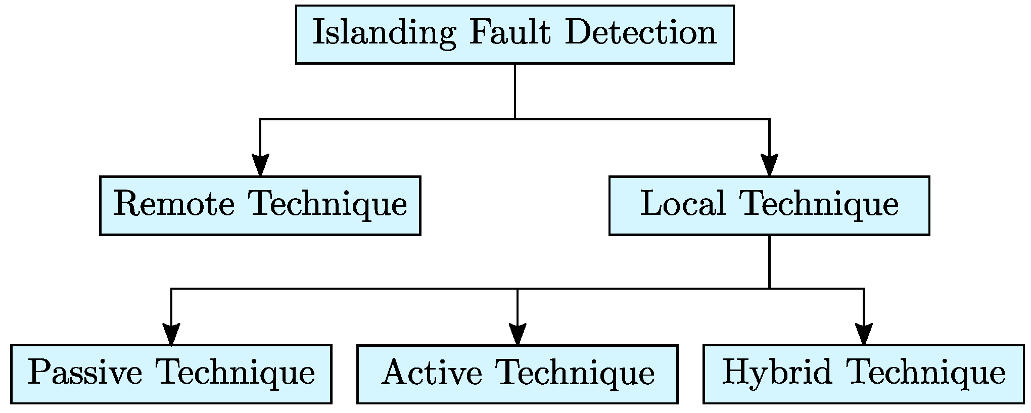
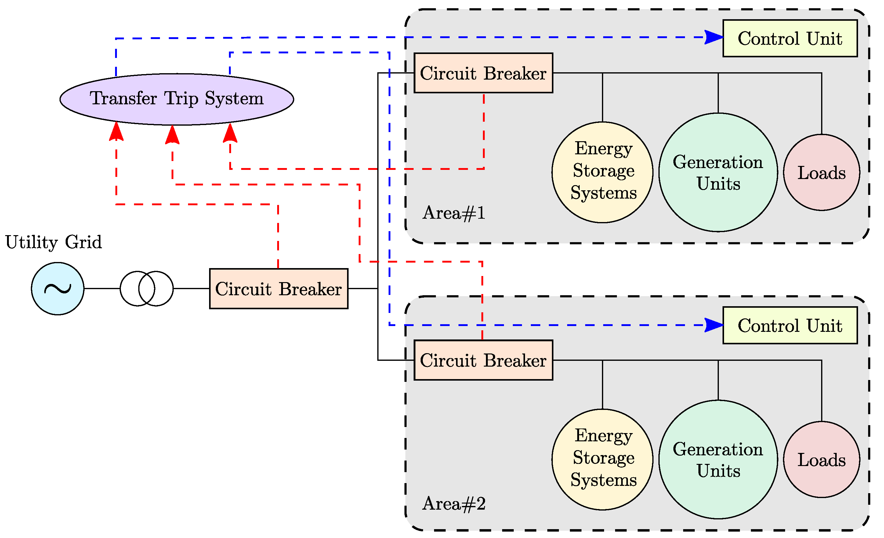
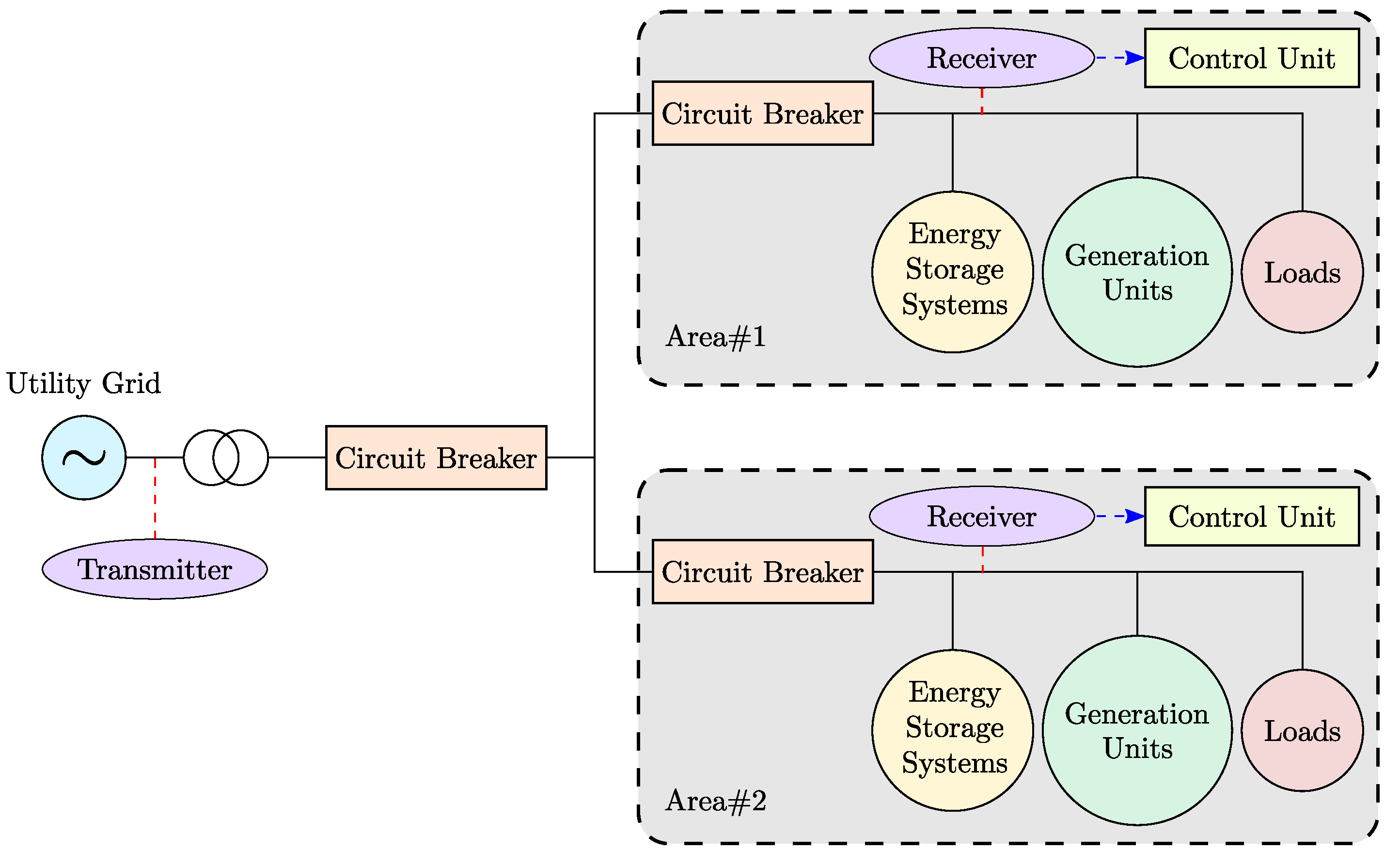
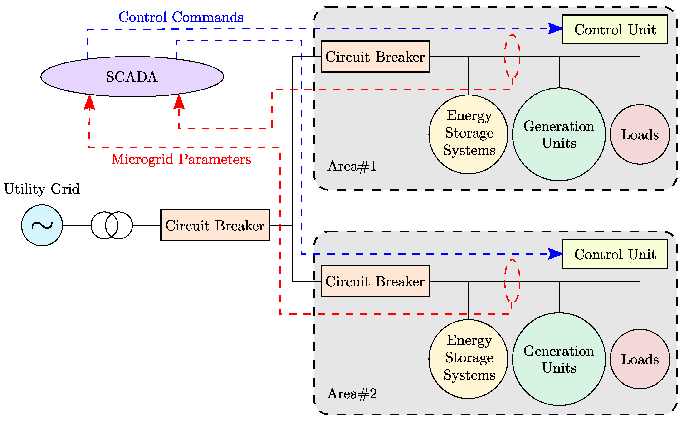
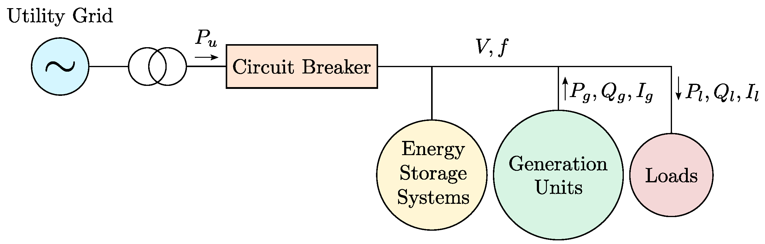
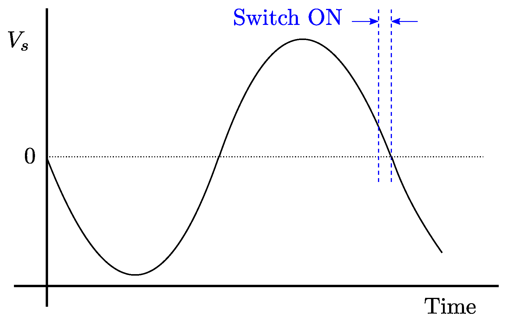
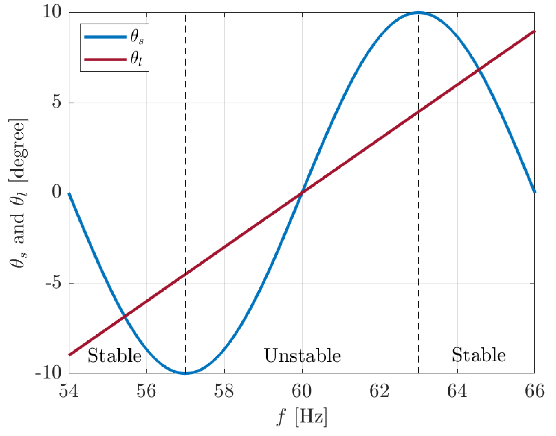
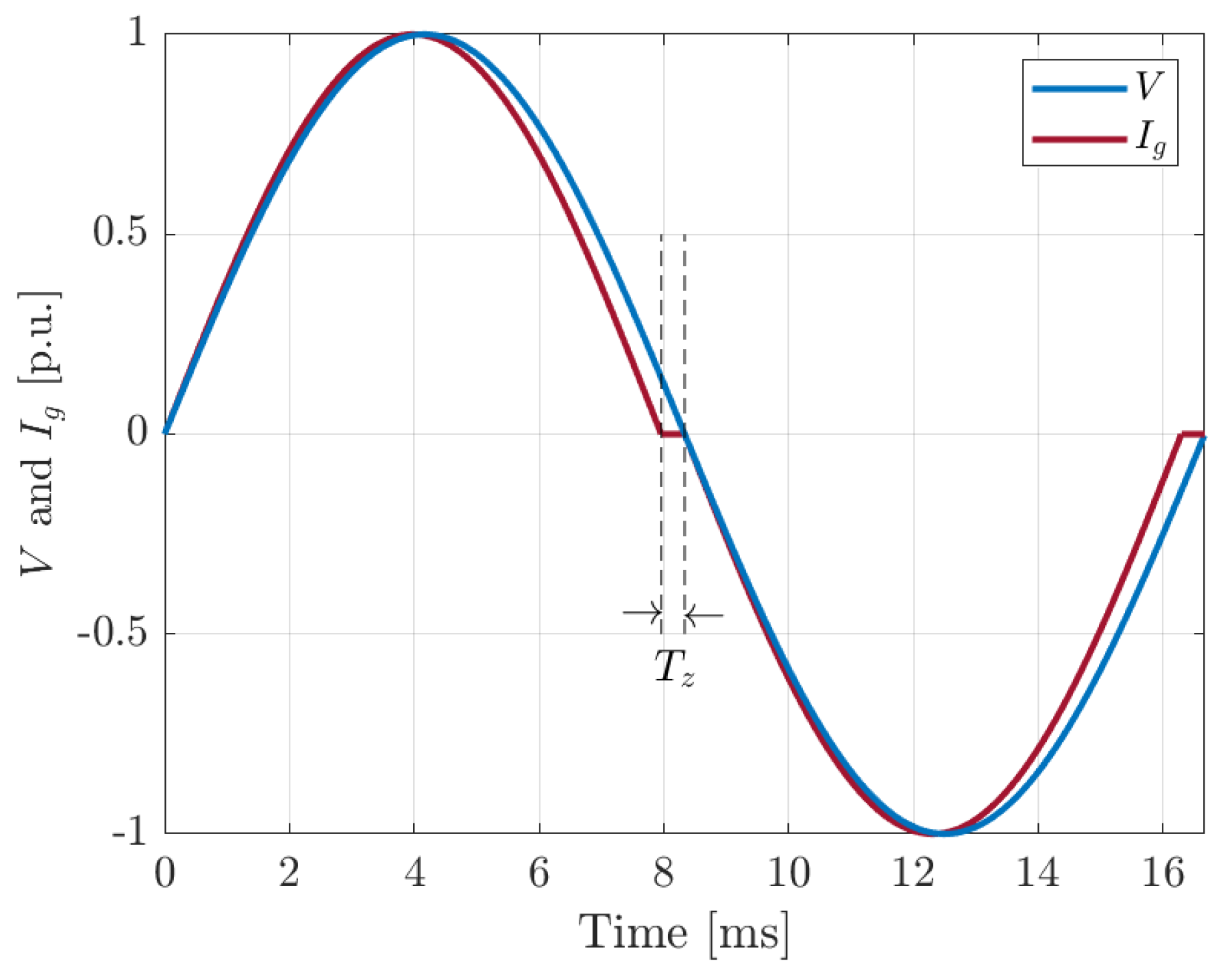
Table 1.
Comparison of islanding fault detection techniques.
| Detection Technique | Detection Principle | Advantages | Disadvantages |
|---|---|---|---|
| Remote Techniques | Sharing the information between the utility grid and the microgrid via a communication channel |
|
|
| Passive Techniques | Monitoring microgird parameters and comparing them with predefined threshold values |
|
|
| Active Techniques | Injecting a perturbation to the system and monitoring the resulting changes in microgrid parameters |
|
|
| Hybrid Techniques | Combining a passive method as the primary detection unit with an active method as the secondary detection unit |
|
|
© 2020 by the authors. Licensee MDPI, Basel, Switzerland. This article is an open access article distributed under the terms and conditions of the Creative Commons Attribution (CC BY) license (http://creativecommons.org/licenses/by/4.0/).
Share and Cite
MDPI and ACS Style
Hosseinzadeh, M.; Rajaei Salmasi, F. Islanding Fault Detection in Microgrids—A Survey. Energies 2020, 13, 3479. https://doi.org/10.3390/en13133479
AMA Style
Hosseinzadeh M, Rajaei Salmasi F. Islanding Fault Detection in Microgrids—A Survey. Energies. 2020; 13(13):3479. https://doi.org/10.3390/en13133479
Chicago/Turabian StyleHosseinzadeh, Mehdi, and Farzad Rajaei Salmasi. 2020. "Islanding Fault Detection in Microgrids—A Survey" Energies 13, no. 13: 3479. https://doi.org/10.3390/en13133479
Note that from the first issue of 2016, this journal uses article numbers instead of page numbers. See further details here.