A Three-Phase Transformerless T-Type- NPC-MLI for Grid Connected PV Systems with Common-Mode Leakage Current Mitigation


 , and
, and
Abstract
:1. Introduction
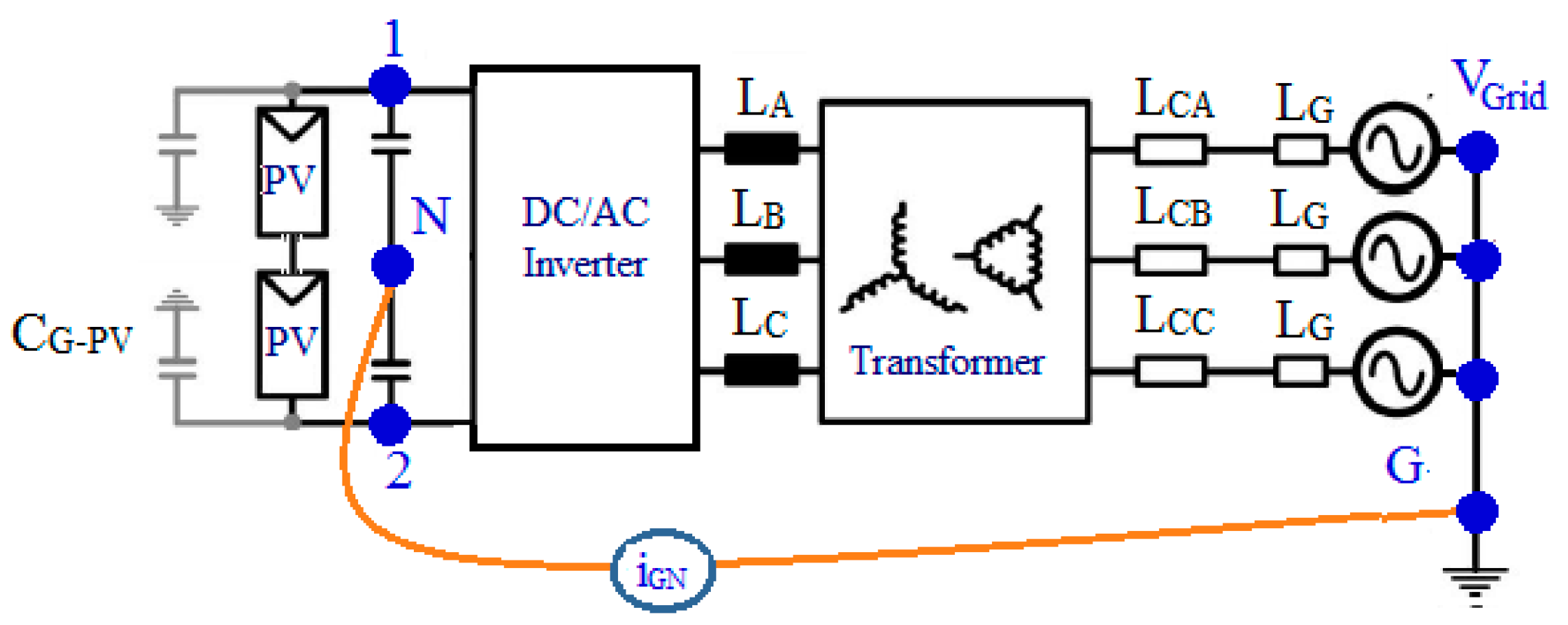
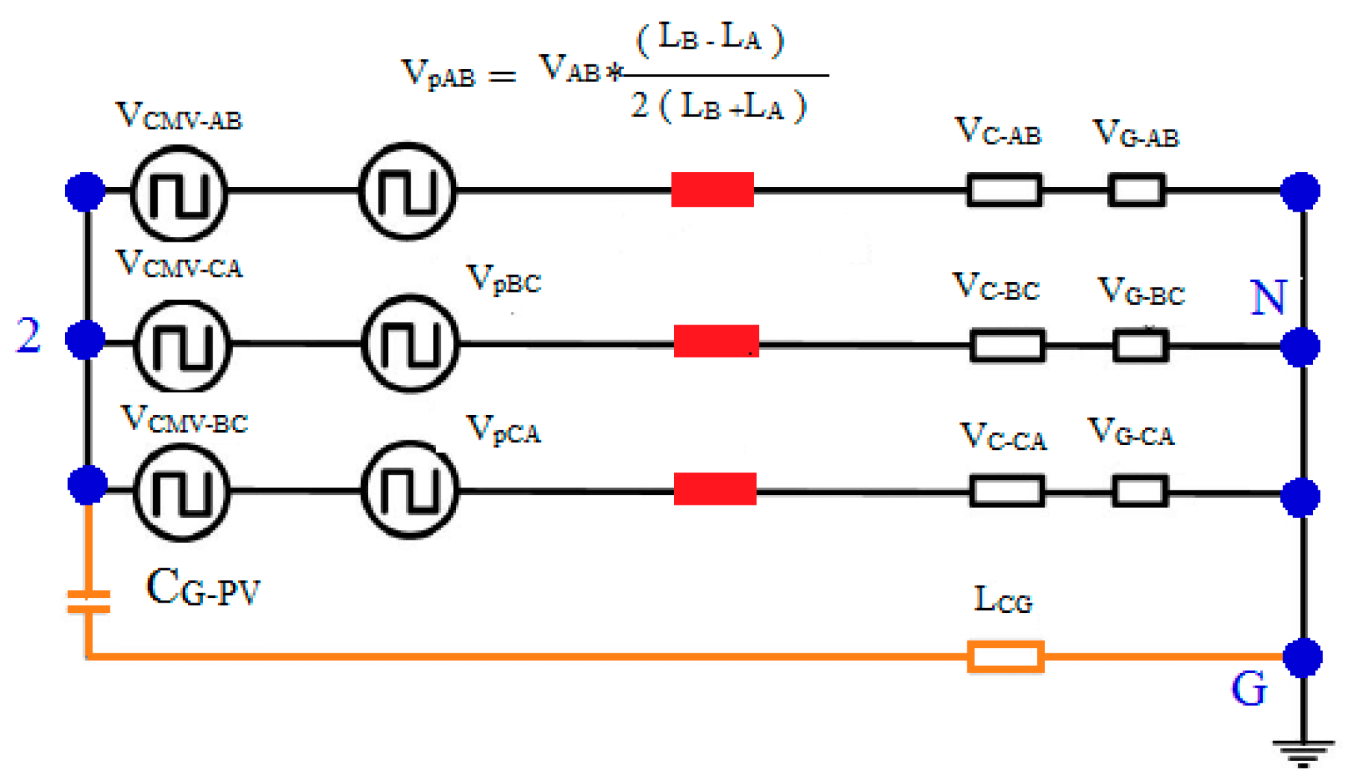
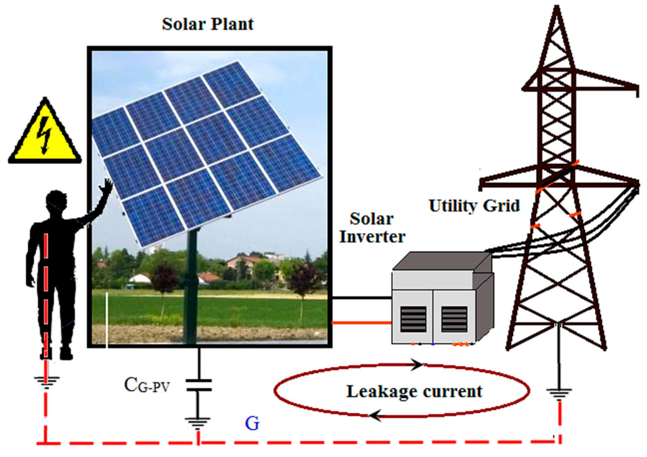
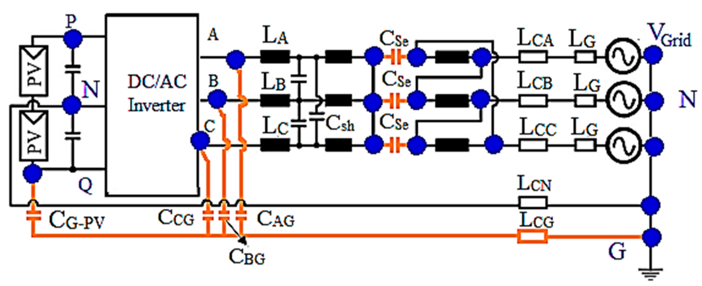
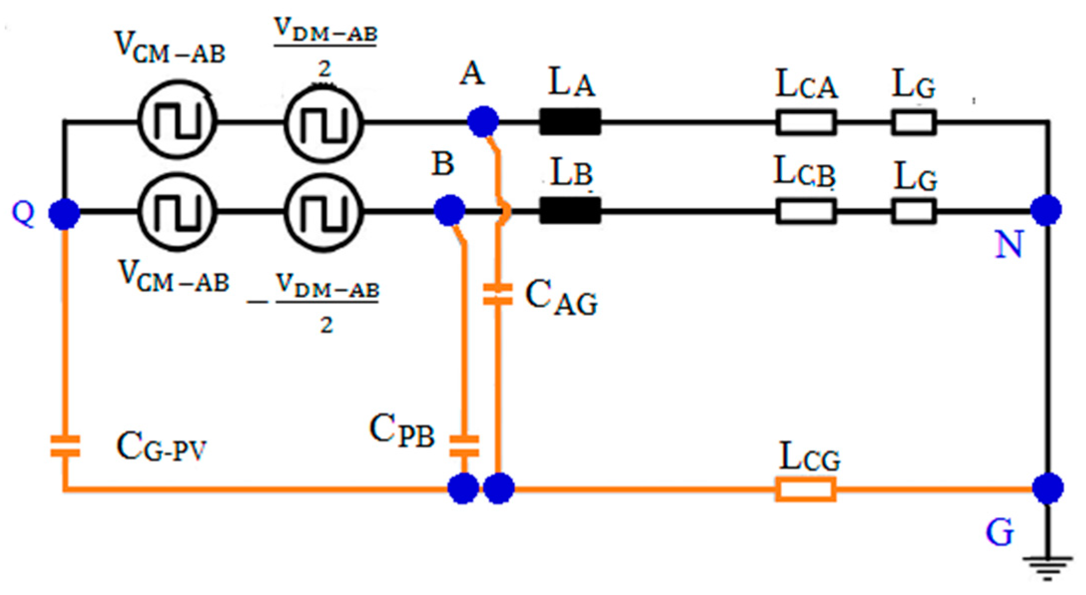
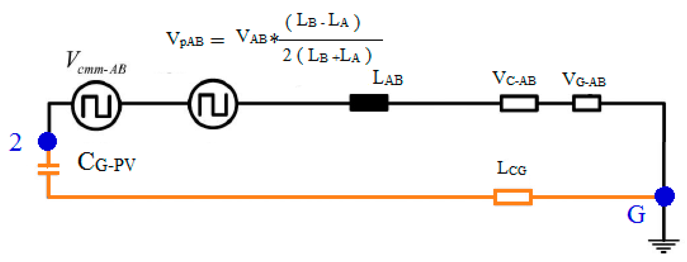
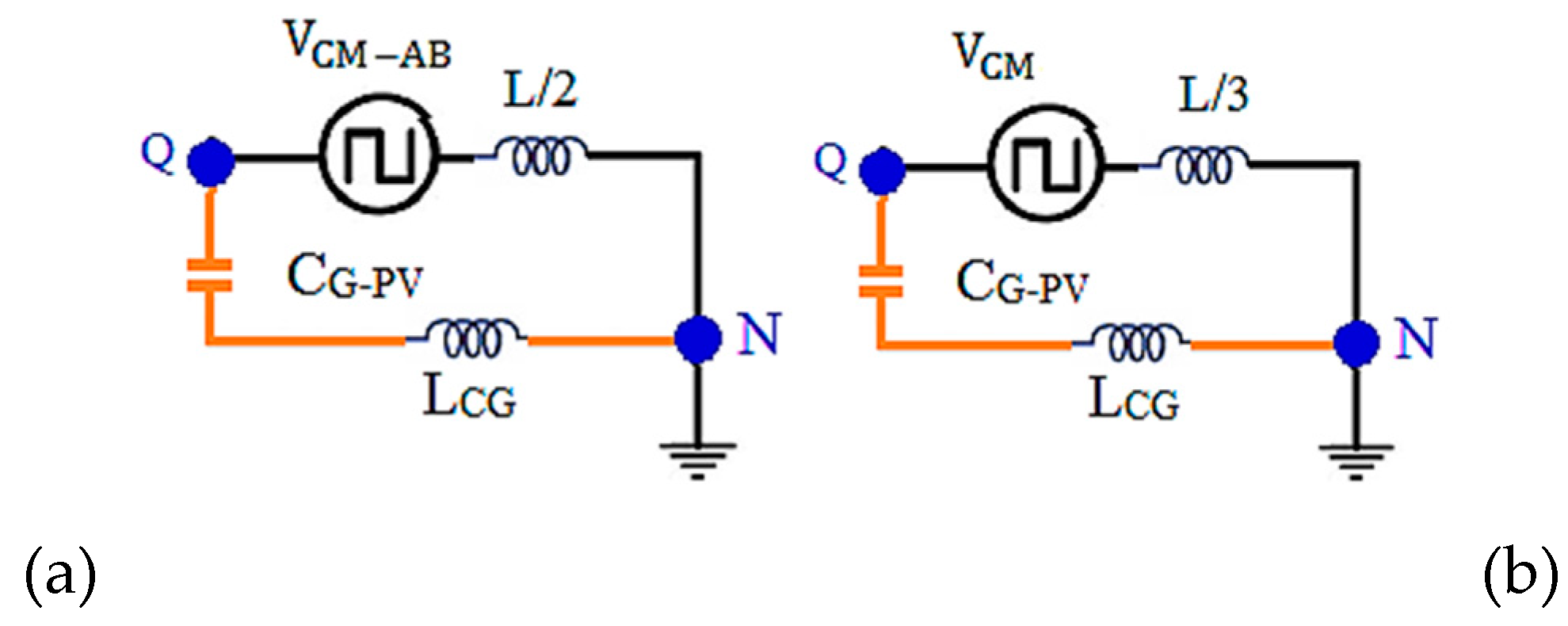
2. Leakage Current Analysis Transformerless PV Inverter System
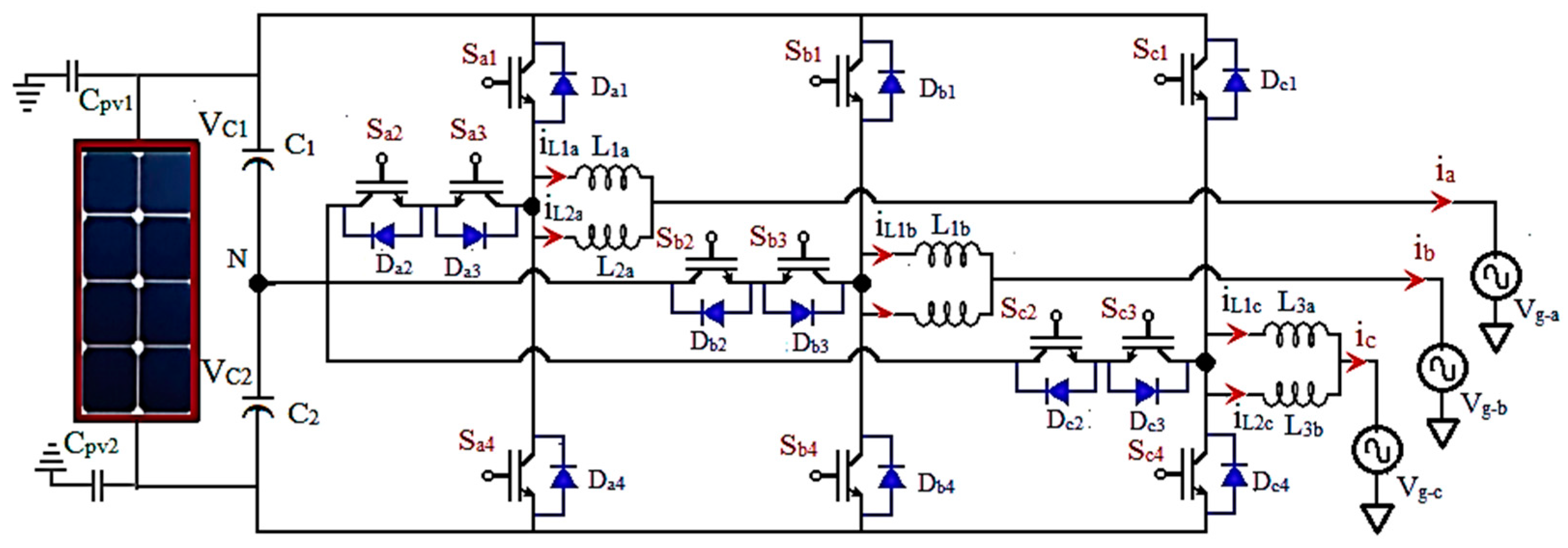
3. Proposed PV Tied Three-Phase Three-Level TL-TNPC-MLI for Grid Connected System with Leakage Current Reduction
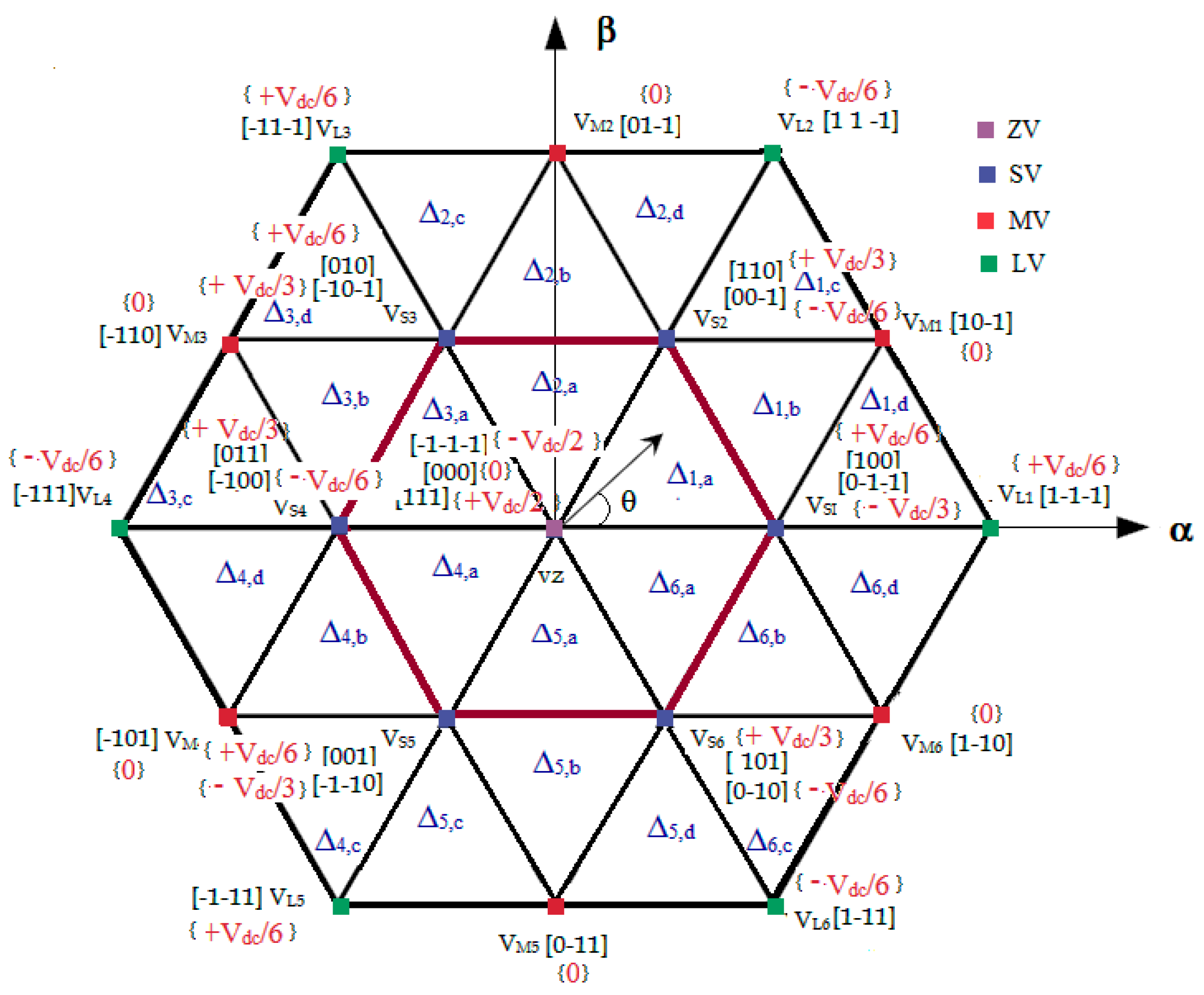
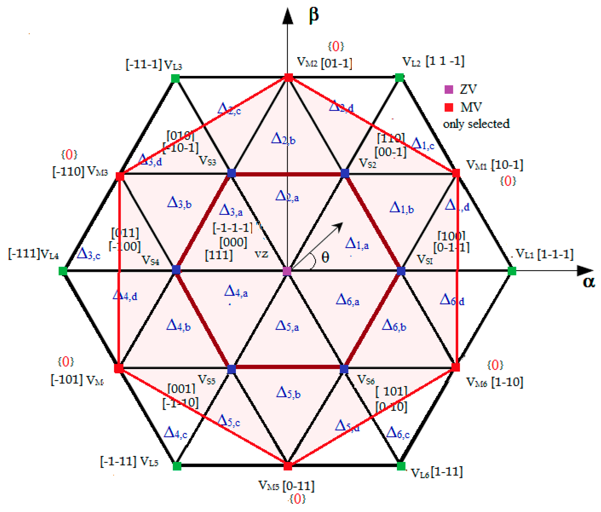
3.1. TL-TNPC-MLI Operation for Zero CMV.
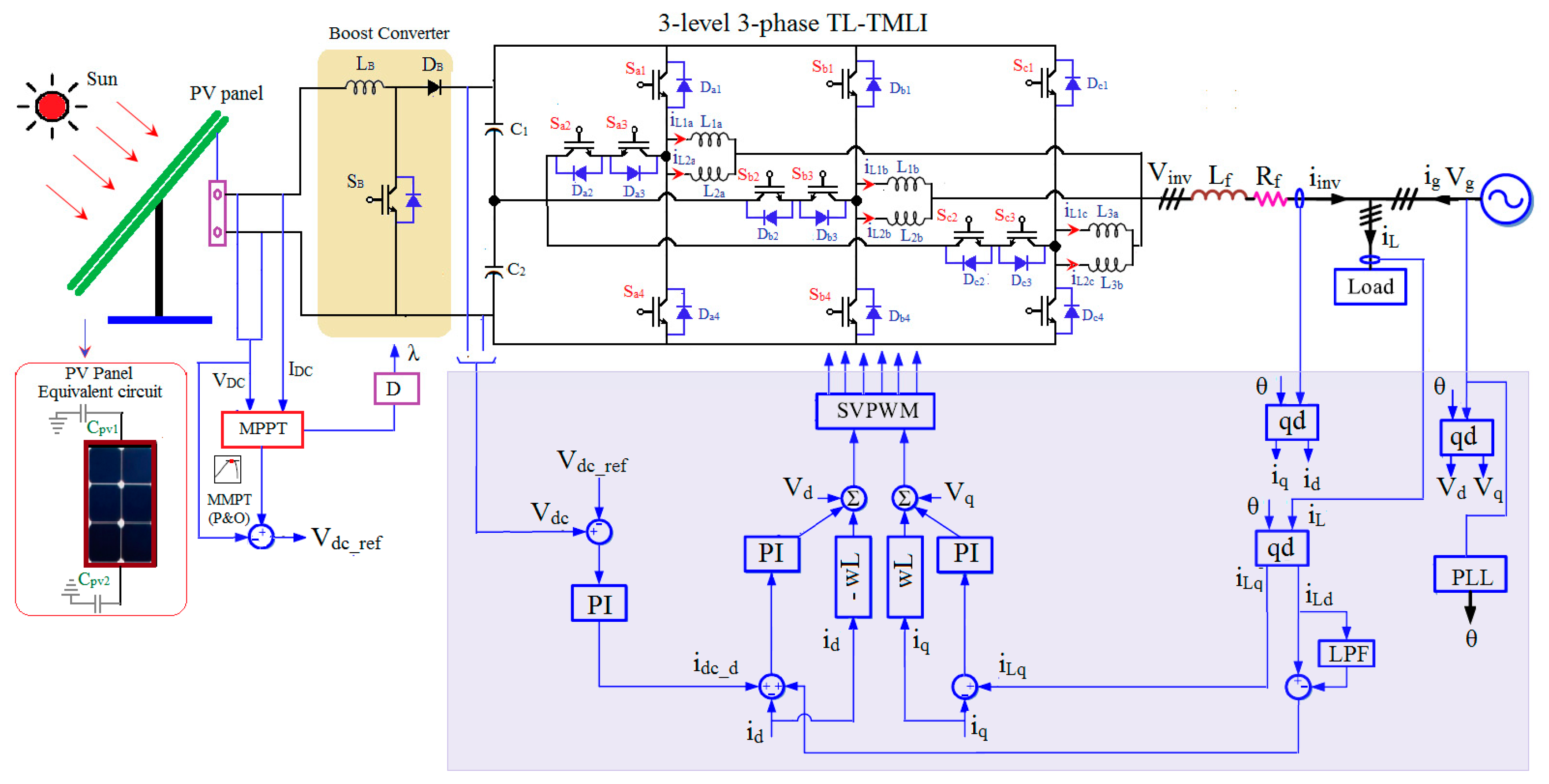
3.2. Proposed Close Loop Grid Connected TL-TNPC-MLI
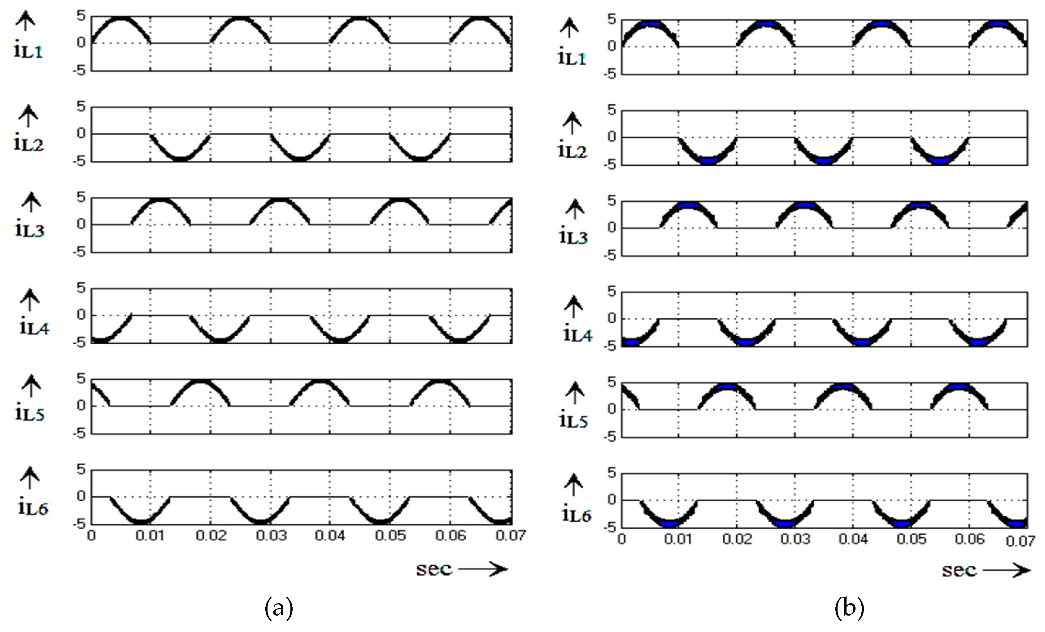
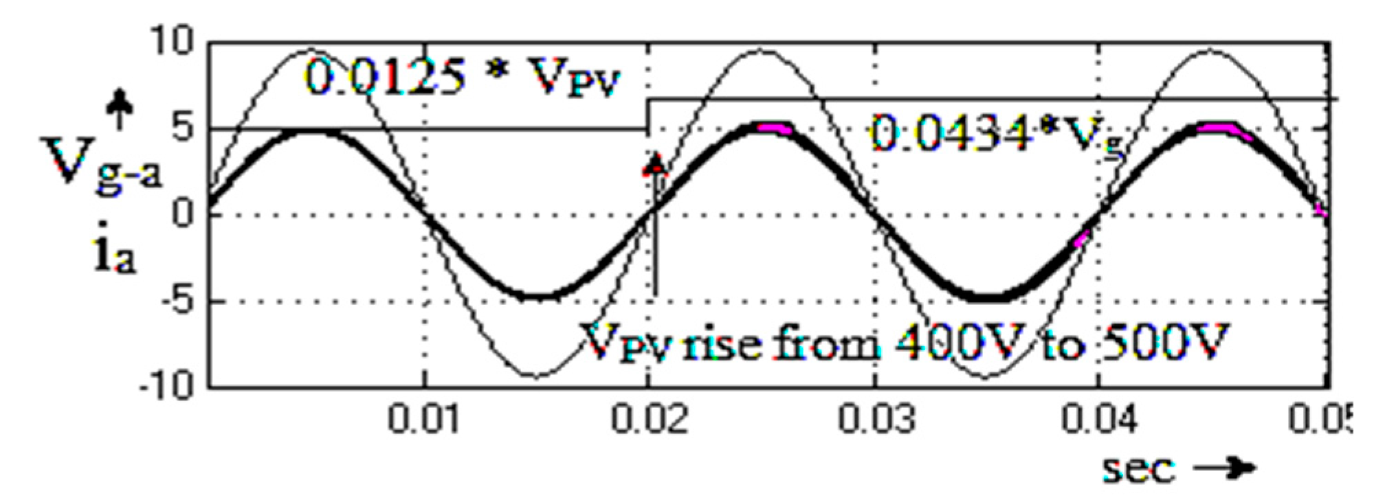
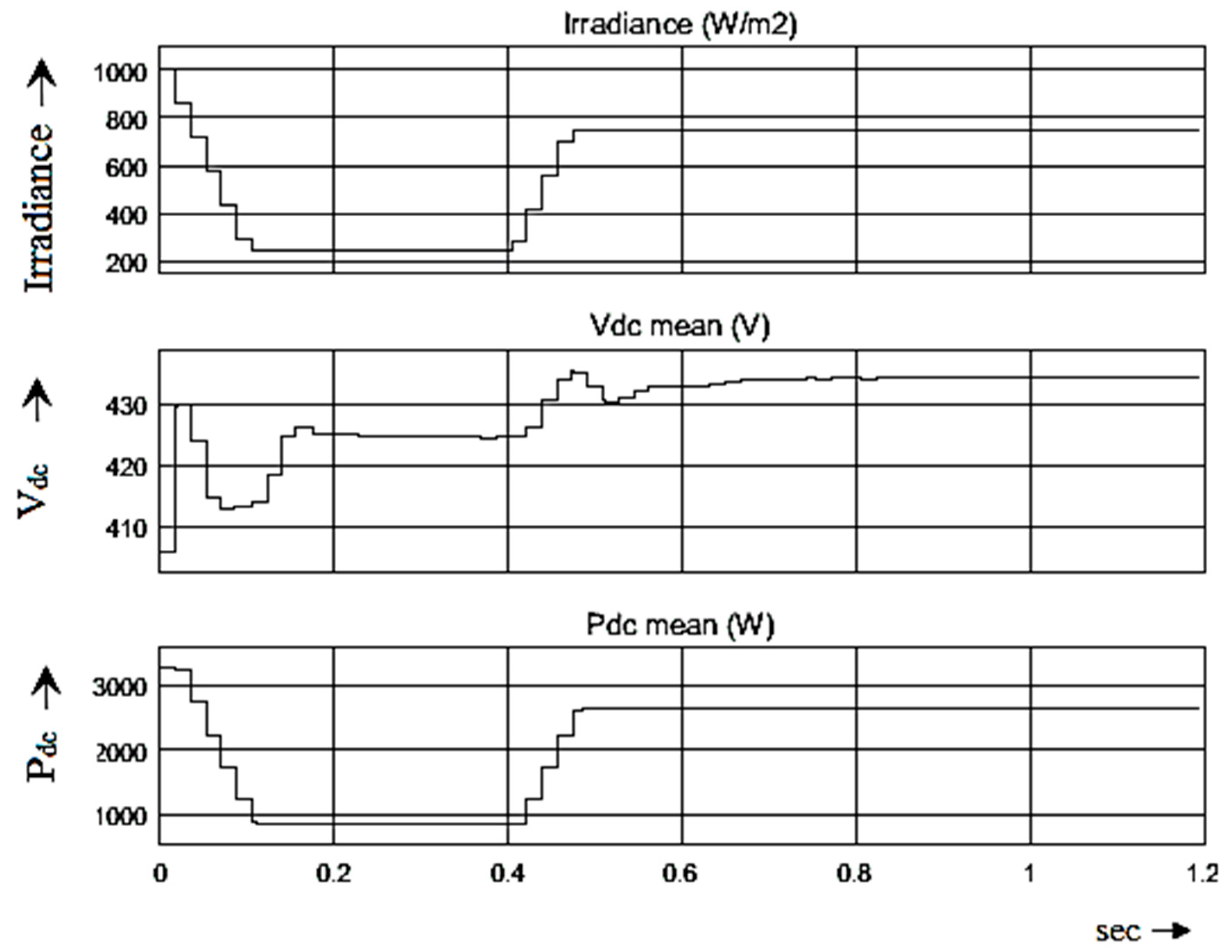
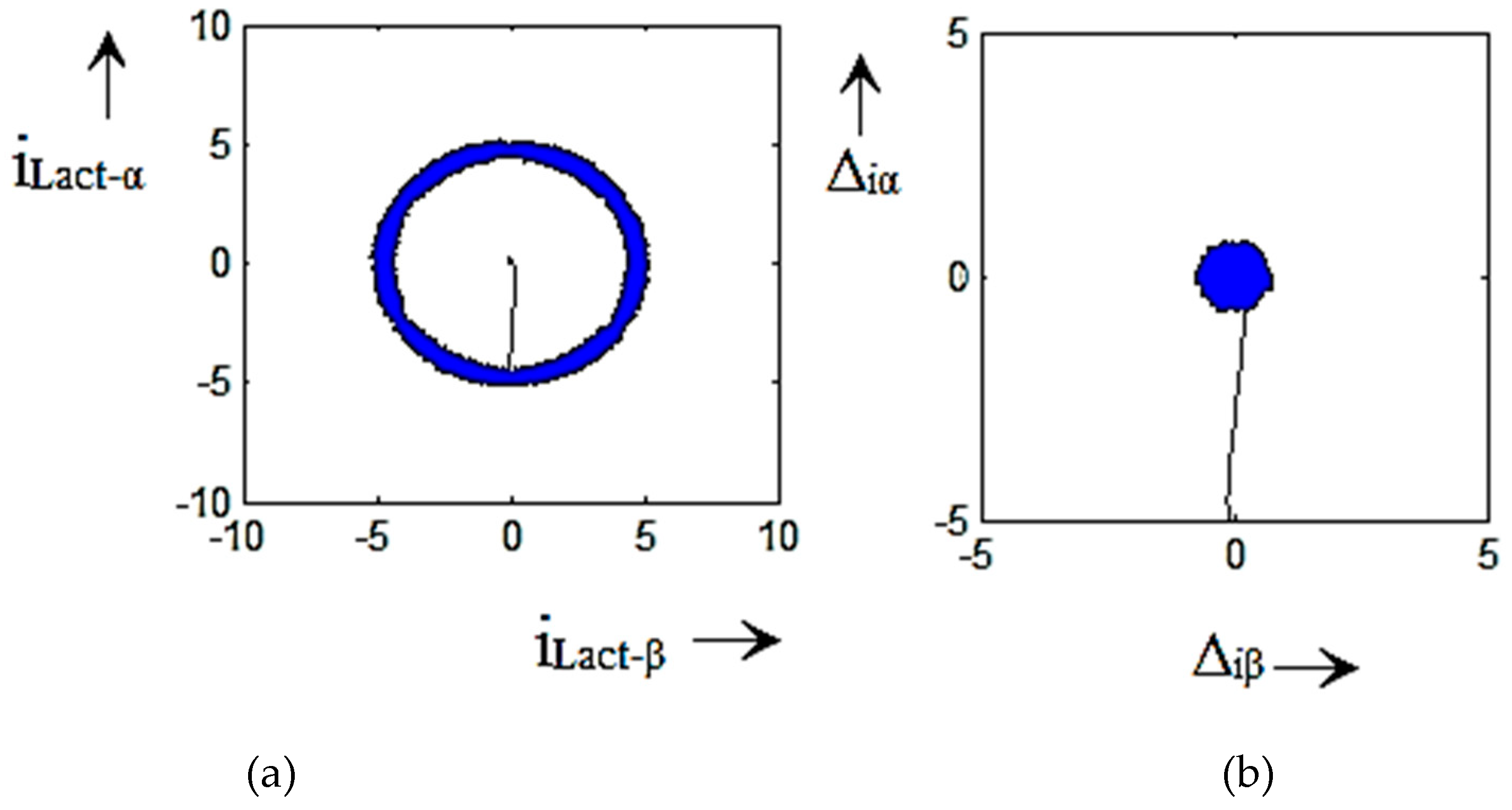
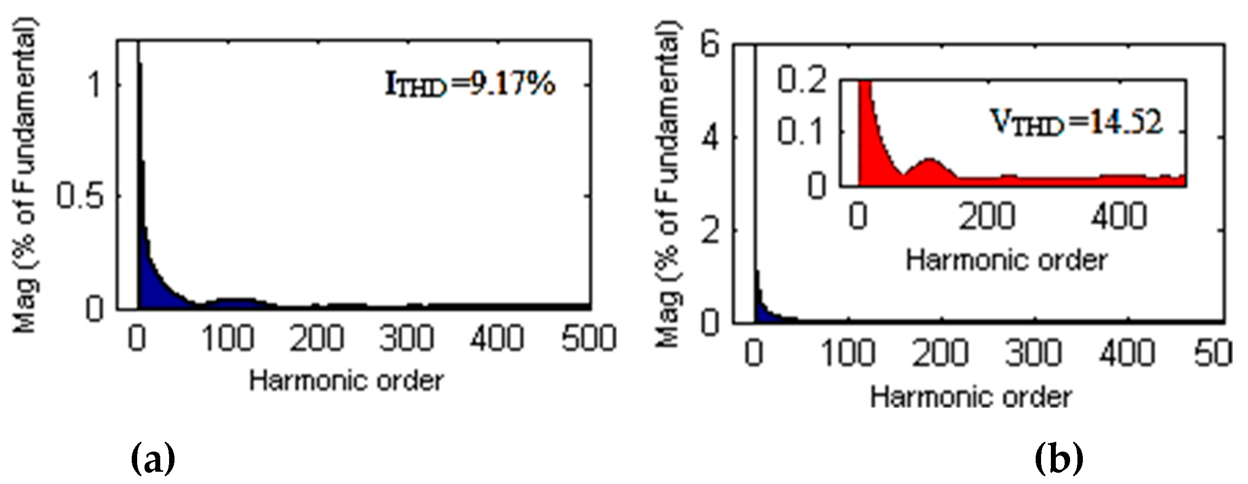
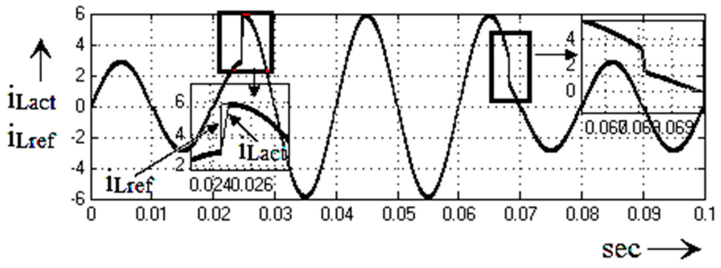
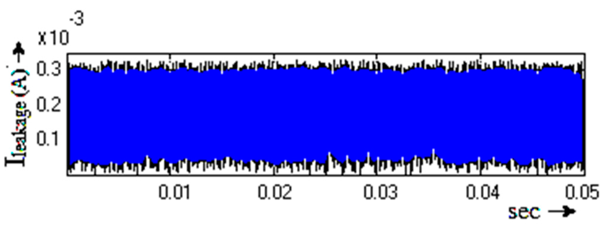
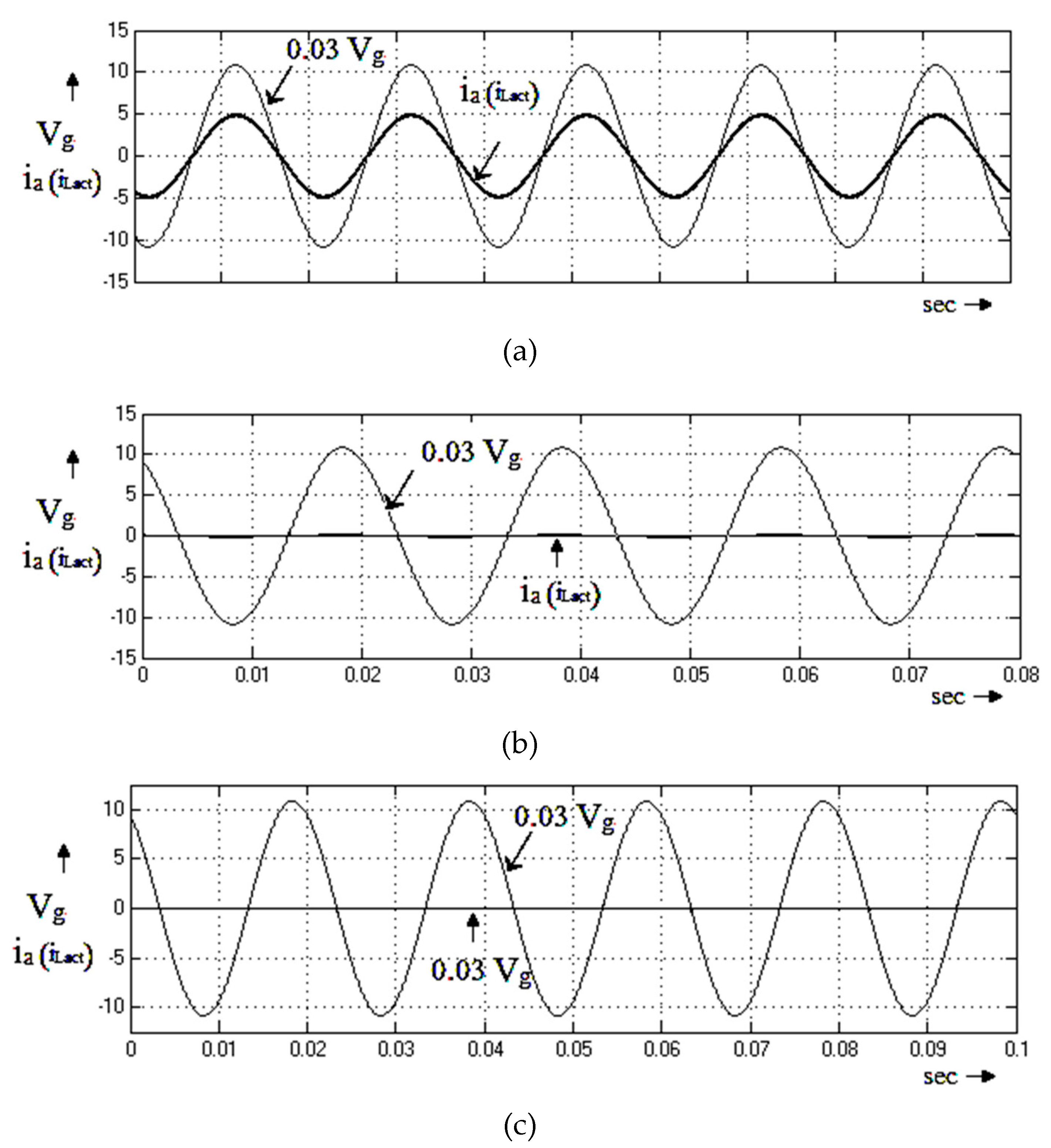
4. Simulation Validation
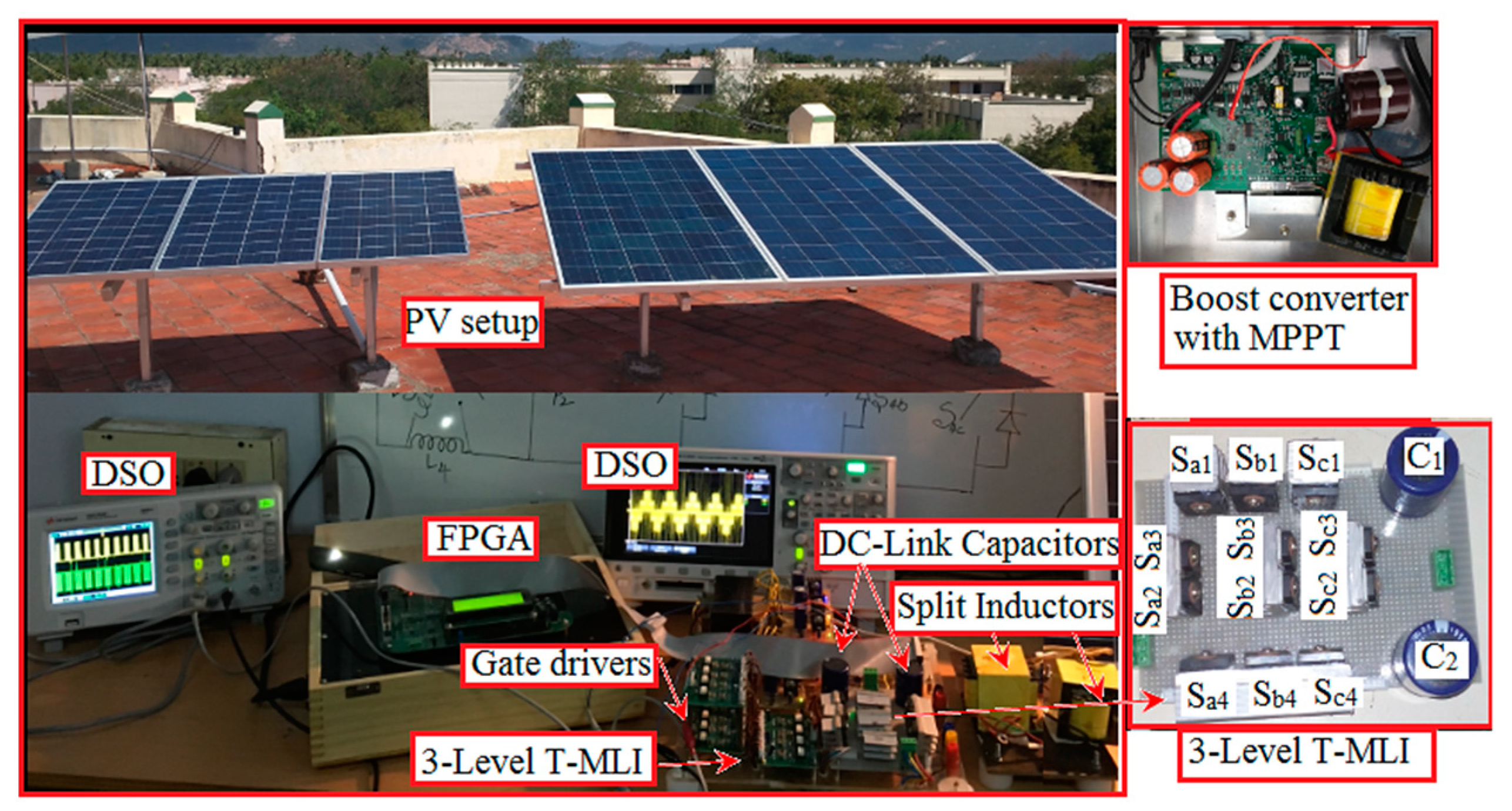
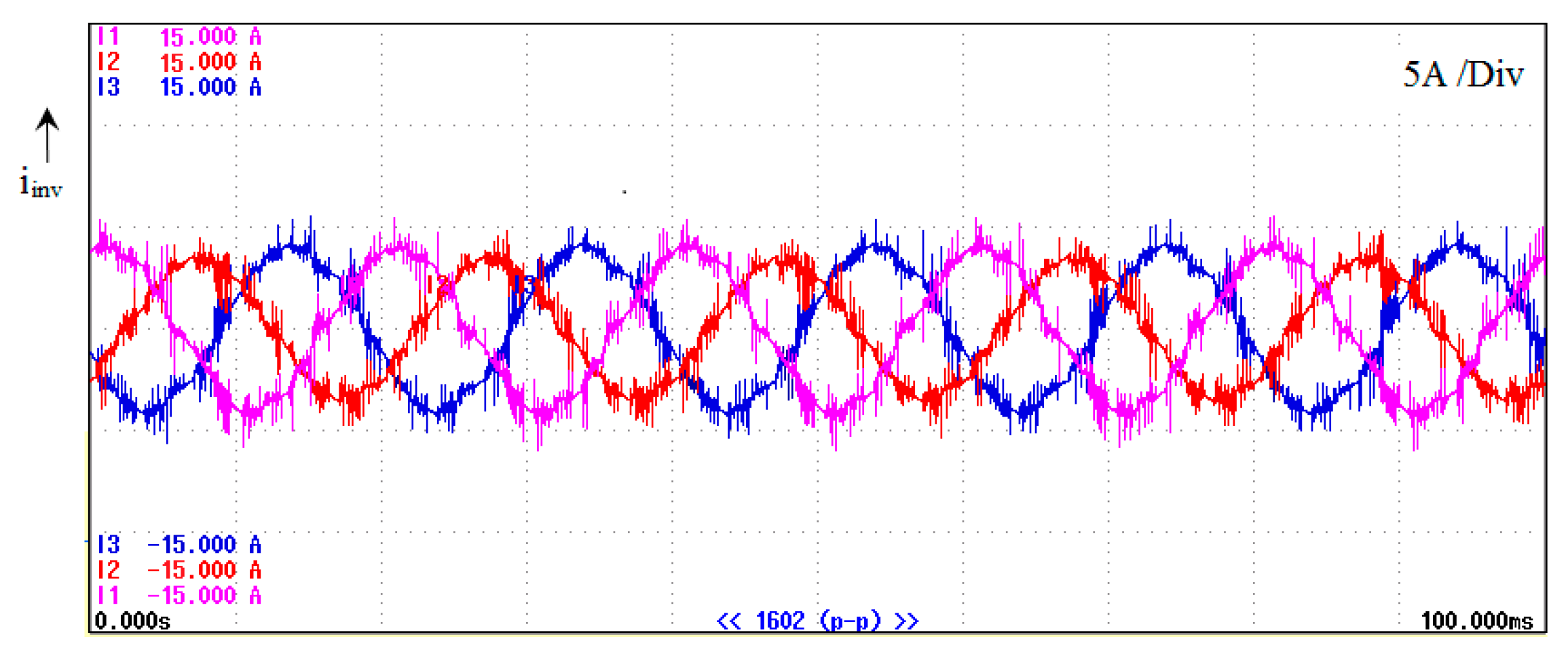
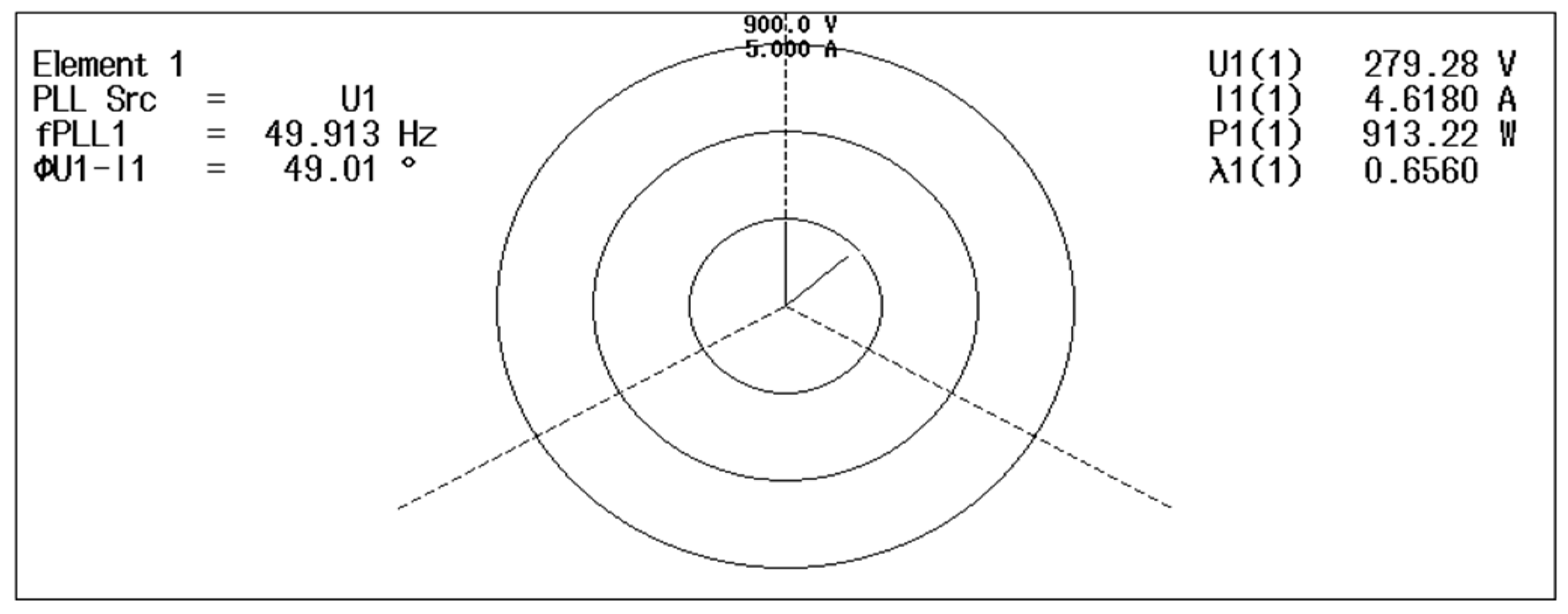
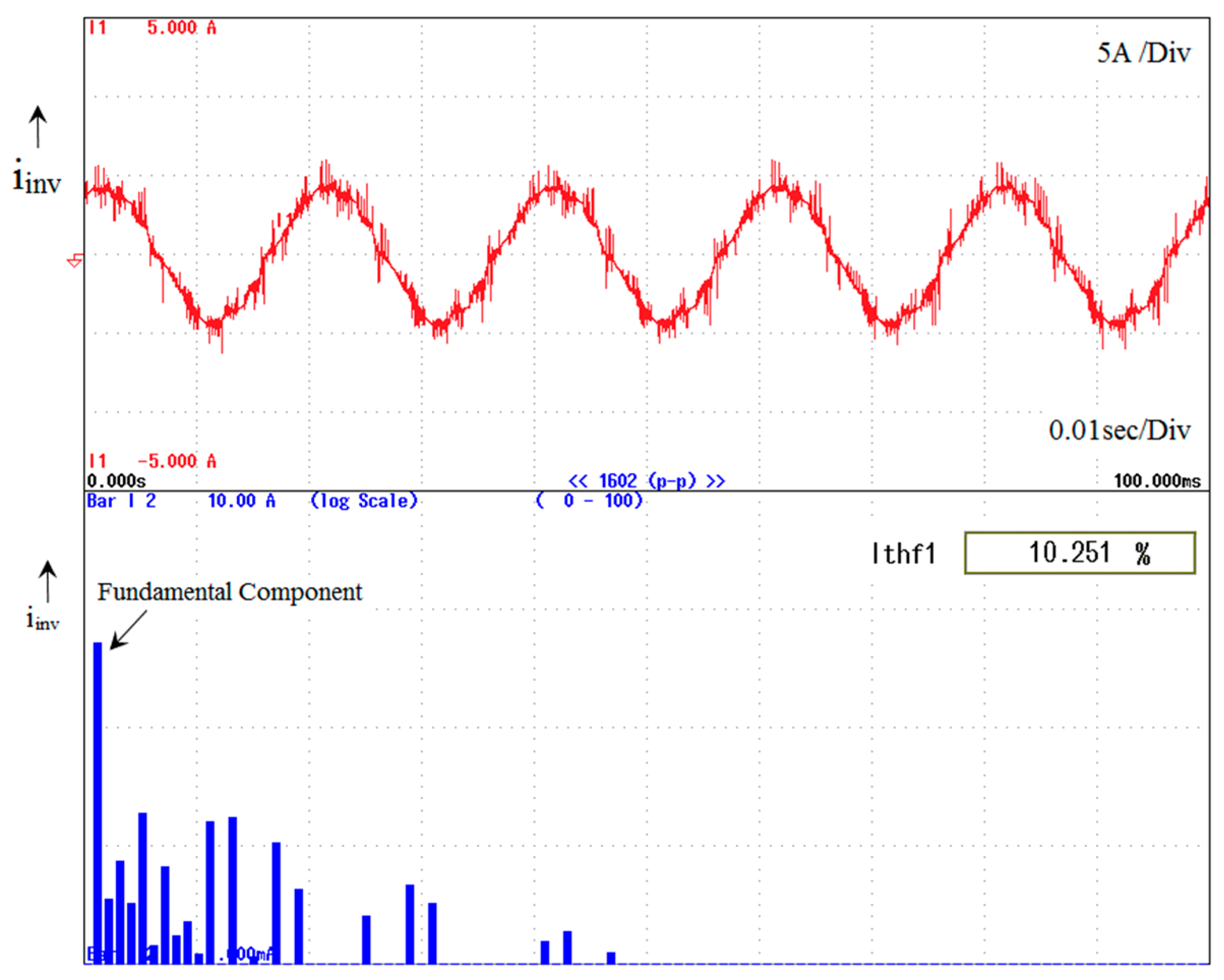
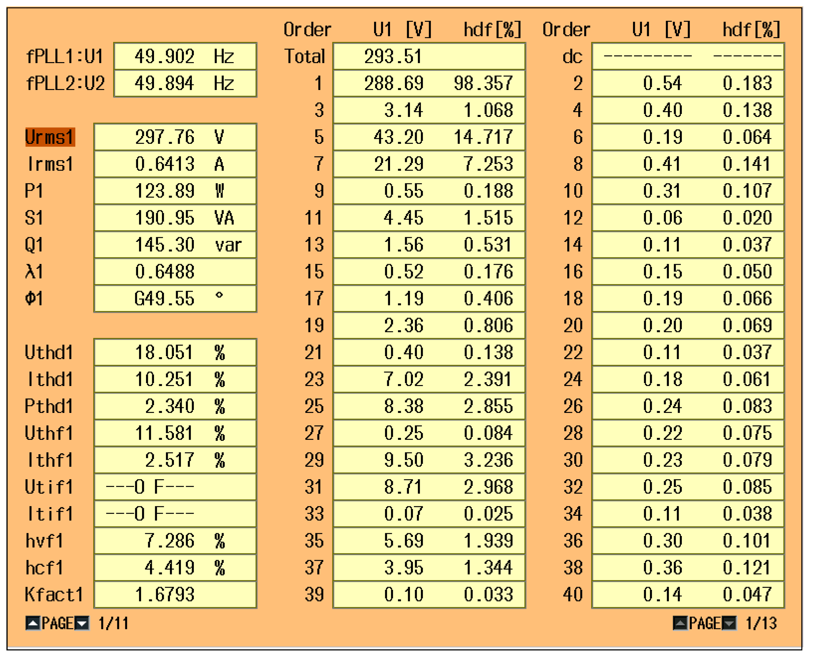
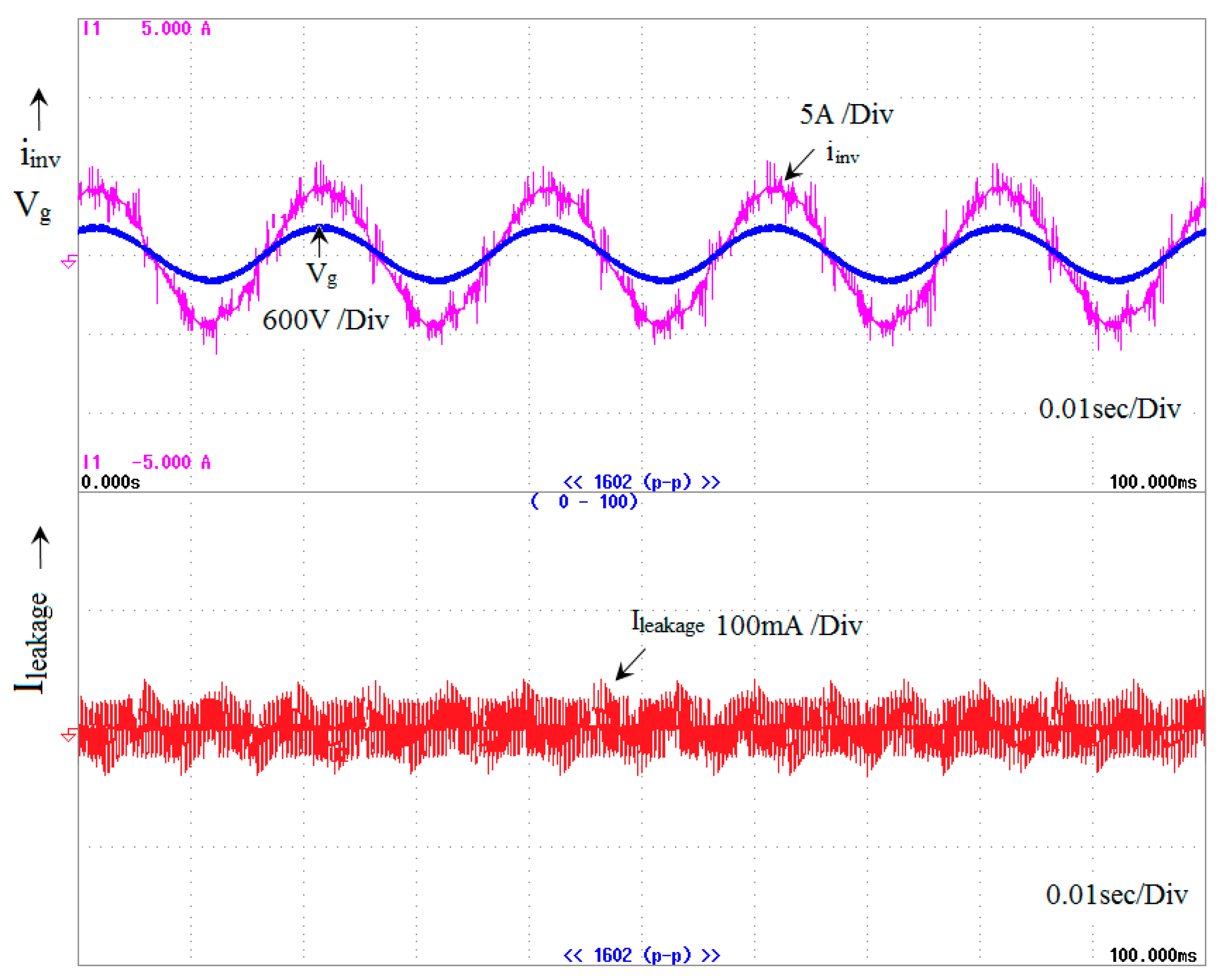
5. Experimental Result
6. Conclusions
Author Contributions
Funding
Conflicts of Interest
Abbreviations
| CG-PV | parasitic capacitances |
| VCM | Common mode voltage |
| VDC | DC-link voltage |
| ICM | Leakage current |
| V* | SVM Reference voltage |
| VZ | Zero voltage vector |
| VS | Small voltage vector |
| VM | Medium voltage vector |
| VZ | Large voltage vector |
| ITCM | Total leakage current |
| Vα and Vβ | α and β SVM coordinated voltage |
| iref | Reference current |
| iact | Actual current |
| Error current | |
| u(t)) | Control input |
| ma | Modulation index |
| fs | Frequency inverter switching pulse |
| f | Grid frequency inverter switching pulse |
| Vg | Grid voltage |
| ∆ei | current error |
| TL | Transformerless inverter |
| TNP-MLI | Neutral point multilevel inverter |
| SVM | Space vector modulation |
| DMV | Common mode voltage |
| SVD | Space vector diagram |
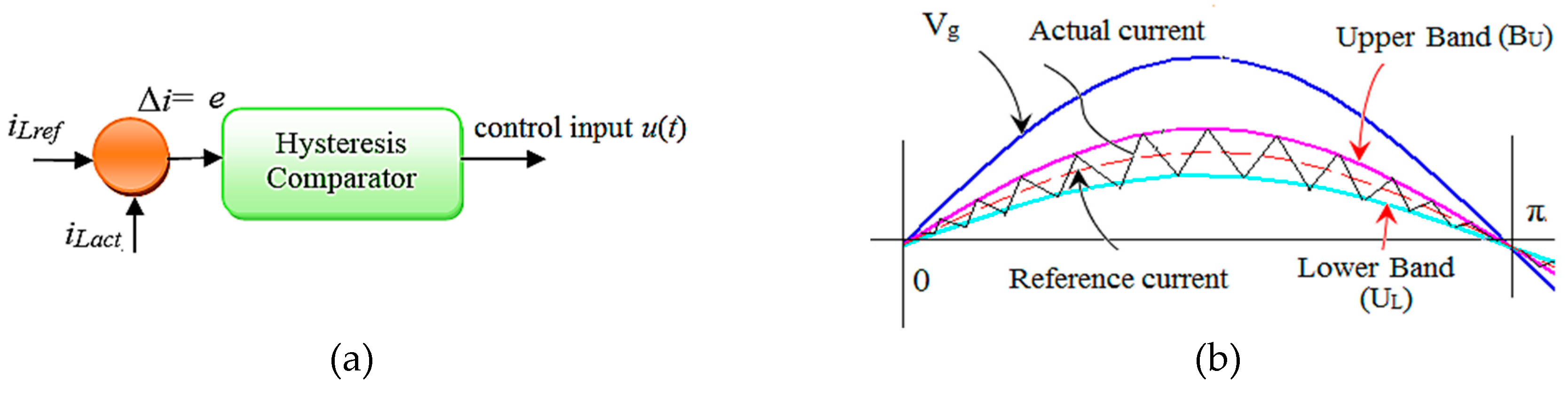
| HCC | hysteresis current control |
| HSVCC | hysteresis Space vector current control |
| MMPT | Maximum power point tracking |
References
- Global Status Report. Renewables; REN21: Paris, France, 2018; ISBN 978-3-9818911-3-3. [Google Scholar]
- Zsiborács, H.; Baranyai, N.H.; Csányi, S.; Vincze, A.; Pintér, G. Economic Analysis of Grid-Connected PV System Regulations: A Hungarian Case Study. Electronics 2019, 8, 149. [Google Scholar] [CrossRef]
- Zsiborács, H.; Baranyai, N.H.; Csányi, S.; Vincze, A.; Pintér, G. Economic and Technical Aspects of Flexible Storage Photovoltaic Systems in Europe. Energies 2018, 11, 1445. [Google Scholar] [CrossRef]
- Sahan, B.; Vergara, A.N.; Henze, N.; Engler, A.; Zacharias, P. A single stage PVmodule integrated converter based on a low-power current source inverter. IEEE Trans. Ind. Electron. 2008, 55, 2602–2609. [Google Scholar] [CrossRef]
- Li, Q.; Wolfs, P. A review of the single phase photovoltaic module integrated converter topologies with three different dc link configuration. IEEE Trans. Power Electron. 2008, 23, 1320–1333. [Google Scholar]
- Lopez, O.; Freijedo, F.D.; Yepes, A.G.; Fernandez Comesana, P.; Malvar, J.; Teodorescu, R.; Doval Gandoy, J. Eliminating ground current in atransformerless photovoltaic application. IEEE Trans. Energy Convers. 2010, 25, 140–147. [Google Scholar] [CrossRef]
- Xiao, H.; Xie, S. Leakage current analytical model and applicationin single-phase transformerless photovoltaic grid-connected inverter. IEEE Trans. Electromagn. Compat. 2010, 52, 902–913. [Google Scholar] [CrossRef]
- VDE-AR-N. 4105: Power Generation Systems Connected to the Low-Voltage Distribution Network—Technical Minimum Requirements for the Connection to and Parallel Operation with Low-Voltage Distribution Networks; DIN_VDE Normo: Berlin, Germany, 2011. [Google Scholar]
- DIN VDE V 0126-1-1. Automatic Disconnection Device between a Generator and the Public Low-Voltage Grid; DIN VDE V 0126-1-1. Berlin, Germany, 2006. Available online: https://www.hylaw.eu/database/national-legislation/germany/din-vde-v-012611-automatic-disconnection-device-between-a-generator-and-the-public-lowv (accessed on 24 June 2019).
- IEEE Application Guide for Std. 1547, IEEE Standard for Interconnecting Distributed Resources with Electric Power Systems; IEEE Standard 1547.2-2008; IEEE: Piscataway, NJ, USA, 2009. [Google Scholar]
- IEC 61727. Photovoltaic (PV) Systems—Characteristics of the Utility Interface; IEC 61727; IEC: Geneva, Switzerland, 2004. [Google Scholar]
- UL 1741. Standard for Inverters, Converters, Controllers, and Interconnection System Equipment for Use with Distributed Energy Resources; UL 1741; UL: Northbrook, IL, USA, 2010. [Google Scholar]
- EN 61000-3-2. Electromagnetic Compatibility (EMC)—Part 3-2: Limits—Limits for Harmonic Current Emissions (Equipment Input Current Under 16 A Per Phase); EN 61000-3-2: Brussels, Belgium, 2006. [Google Scholar]
- Steca Grid. Available online: www.steca.com (accessed on 24 June 2019).
- Goodway. Available online: www.goodwe.com (accessed on 24 June 2019).
- Goodrich, A.; James, T.; Woodhouse, M. Residential, Commercial, Utility-Scale Photovoltaic (PV) System Prices in the United States: Current drivers and Cost-Reduction Opportunities; Nat. Renewable Energy Lab.: Golden, CO, USA, 2012.
- Feldman, D.; Margolis, R.; Bolinger, M.; Chung, D.; Fu, R.; Seel, J.; Wiser, R. Photovoltaic System Pricing Trends: Historical, RecentNear-Term Projections, 2013th ed.; U.S. Dept. Energy: Oak Ridge, TN, USA, 2013.
- Koutroulis, E.; Blaabjerg, F. Design optimization of transformerless grid-connected PV inverters including reliability. IEEE Trans. Power Electron. 2013, 28, 325–335. [Google Scholar] [CrossRef]
- Rodriguez, J.; Bernet, S.; Steimer, P.K.; Lizama, I.E. A survey on neutral-point-clamped inverters. IEEE Trans. Ind. Electron. 2010, 57, 2219–2230. [Google Scholar] [CrossRef]
- Bharatiraja, C.; Jeevananthan, S.; Munda, J.L.; Latha, R. Improved SVPWM vector selection approaches in OVM region to reduce common-mode voltage for three-level neutral point clamped inverter. Int. J. Electr. Power Energy Syst. 2016, 79, 285–297. [Google Scholar] [CrossRef]
- Selvaraj, R.; Chelliah, T.R.; Khare, D.; Bharatiraja, C. Fault Tolerant Operation of Parallel-Connected 3L-Neutral-Point Clamped Back-to-Back Converters Serving to Large Hydro-Generating Units. IEEE Trans. Ind. Appl. 2018, 54, 5429–5443. [Google Scholar] [CrossRef]
- Maheshwari, R.; Munk-Nielsen, S.; Busquets-Monge, S. Design of neutral-point voltage controller of a three-level NPC inverter with small DC-link capacitor. IEEE Trans. Ind. Electron. 2013, 60, 1861–1871. [Google Scholar] [CrossRef]
- Bharatiraja, C.; Jeevananthan, S.; Latha, R. FPGA based practical implementation of NPC-MLI with SVPWM for an autonomous operation PV system with capacitor balancing. Int. J. Electr. Power Energy Syst. 2014, 61, 489–509. [Google Scholar] [CrossRef]
- Bharatiraja, C.; Jeevananthan, S.; Latha, R. Vector Selection Approach-based Hexagonal Hysteresis Space Vector Current Controller for a Three-phase Diode Clamped MLI with Capacitor Voltage Balancing. IET Power Electron. 2016, 9, 1350–1361. [Google Scholar] [CrossRef]
- Yong Wang, W.W.; Shi, N.X.; Wang, C.M. Diode-Free T-Type Three-Level Neutral-Point-Clamped Inverter for Low-Voltage Renewable Energy System. IEEE Trans. Ind. Electron. 2014, 61, 6168–6174. [Google Scholar] [CrossRef]
- Schweizer, M.; Kolar, J.W. Design and implementation of a highly efficient three-level T-type converter for low-voltage applications. IEEE Trans. Power Electron. 2013, 28, 899–907. [Google Scholar] [CrossRef]
- Chokkalingam, B.; Bhaskar, M.S.; Padmanaban, S.; Vigna, K.R.; Iqbal, A. Investigations of Multi-Carrier Pulse Width Modulation Schemes for Diode Free Neutral Point Clamped Multilevel Inverters. J. Power Electron. 2019, 19, 702–713. [Google Scholar]
- Bharatiraja, C.; Sanjeevikumar, P.; Blaabjerg, F. Critical Investigation and Comparative Analysis of Advanced PWM Techniques for Three-Phase Three-Level NPC-MLI Drives. Electr. Power Compon. Syst. 2018, 46, 258–269. [Google Scholar]
- Bharatiraja, C.; Jeevananthan, S.; Munda, J.L. Timing Correction Algorithm for SVPWM Based Diode-Clamped MLI Operated in overmodulation Region. IEEE J. Sel. Top. Power Electron. Appl. 2018, 6, 233–245. [Google Scholar] [CrossRef]
- Santhakumar, C.; Shivakumar, R.; Bharatiraja, C.; Sanjeevikumar, P. Carrier shifting algorithms for the mitigation of circulating current in diode clamped MLI fed induction motor drive. Int. J. Power Electron. Drive Syst. 2017, 8, 844–852. [Google Scholar] [CrossRef]
- Bharatiraja, C.; Raghu, S.; Rao, K.R.S. Comparative analysis of different PWM techniques to reduce the common mode voltage in three-level neutral-point- clamped inverters for variable speed induction drives. Int. J. Power Electron. Drive Syst. 2013, 3, 105–116. [Google Scholar]
- Lyu, J.G.; Wang, J.D.; Hu, W.B.; Wu, Z.F. Research on the Neutral-Point Voltage Balance for NPC Three-Level Inverters under Non-Ideal Grid Conditions. Energies 2018, 11, 1331. [Google Scholar] [CrossRef]
- Wang, Y.; Xu, Q.; Ma, Z.; Zhu, H. An Improved Control and Energy Management Strategy of Three-Level NPC Converter Based DC Distribution Network. Energies 2017, 10, 1635. [Google Scholar] [CrossRef]
- Chen, Z.; Yu, W.; Ni, X.; Huang, A. A new modulation technique to reduce leakage current without compromising modulation index in PV systems. In Proceedings of the 2015 IEEE Energy Conversion Congress and Exposition (ECCE), Montreal, QC, Canada, 20–24 September 2015. [Google Scholar]
- Zhang, L.; Sun, K.; Feng, L.; Wu, H.; Xing, Y. A Family of Neutral Point Clamped Full-Bridge Topologies for Transformerless Photovoltaic Grid-Tied Inverters. IEEE Trans. Power Electron. 2013, 28, 730–739. [Google Scholar] [CrossRef]
- Hashempour, M.M.; Yang, M.Y.; Lee, T.L. An Adaptive Control of DPWM for Clamped-Three-Level Photovoltaic Inverters With Unbalanced Neutral-Point Voltage. IEEE Trans. Ind. Appl. 2018, 54, 6133–6148. [Google Scholar] [CrossRef]
- Cavalcanti, M.C.; Farias, A.M.; Oliveira, K.C.; Neves, F.A.S.; Afonso, J.L. Eliminating leakage currents in neutral point clamped inverters for photovoltaic system. IEEE Trans. Ind. Electron. 2012, 59, 435–443. [Google Scholar] [CrossRef]
- Araujo, S.; Zacharias, P.; Mallwitz, R. Highly efficient single-phase transformerless inverters for grid-connected photovoltaic systems. IEEE Trans. Ind. Electron. 2010, 57, 3118–3128. [Google Scholar] [CrossRef]
- Albalawi, H.; Zaid, S.A. An H5 Transformerless Inverter for Grid Connected PV Systems with Improved Utilization Factor and a Simple Maximum Power Point Algorithm. Energies 2018, 11, 2912. [Google Scholar] [CrossRef]
- Selvamuthukumaran, R.; Garg, A.; Gupta, R. Hybrid Multicarrier Modulation to Reduce Leakage Current in a Transformerless Cascaded Multilevel Inverter for Photovoltaic Systems. IEEE Trans. Power Electron. 2015, 30, 1779–1783. [Google Scholar] [CrossRef]
- Lopez, O.; Teodorescu, R.; Doval-Gandoy, J. Multilevel transformerless topologies for single-phase grid-connected converters, 32nd Annual Conf. onIEEE Industrial Electronics. IECON 2006, 1, 5191–5196. [Google Scholar]
- Kwon, J.M.; Nam, K.H.; Kwon, B.H. Photovoltaic power conditioning system with line connection. IEEE Trans. Ind. Electron. 2006, 53, 1048–1054. [Google Scholar] [CrossRef]
- Bharatiraja, C.; Padmanaban, S.; Siano, P.; Leonowicz, Z.; Iqbal, A. A hexagonal hysteresis space vector current controller for single Z-source network multilevel inverter with capacitor balancing. In Proceedings of the 2017 IEEE International Conference on Environment and Electrical Engineering and 2017 IEEE Industrial and Commercial Power Systems Europe, Milan, Italy, 6–9 June 2017. [Google Scholar]
- Wang, J.; Zhai, F.; Wang, J.; Jiang, W.; Li, J.; Li, L.; Huang, X. A Novel Discontinuous Modulation Strategy with Reduced Common Mode Voltage and Removed DC Offset on Neutral Point Voltage for Neutral Point Clamped Three Level Converter. IEEE Trans. Power Electron. 2018, 6, 1966–1978. [Google Scholar] [CrossRef]
- Bae, Y.; Kim, R.Y. Suppression of Common-Mode Voltage Using a Multicentral Photovoltaic Inverter Topology With Synchronized PWM. IEEE Trans. Ind. Electron. 2014, 61, 4722–4733. [Google Scholar] [CrossRef]
- Hu, X.; Ma, P.; Gao, B.; Zhang, M. An Integrated Step Up Inverter Without Transformer and Leakage Current for Grid-Connected Photovoltaic System. IEEE Trans. Power Electron. 2019. [Google Scholar] [CrossRef]
- Lee, J.S.; Lee, K.-B. New Modulation Techniques for a Leakage Current Reduction and a Neutral-Point Voltage Balance in Transformerless Photovoltaic Systems Using a Three-Level Inverter. IEEE Trans. Power Electron. 2014, 29, 1720–1732. [Google Scholar] [CrossRef]


| State | Vout | Sa1 | Sa2 | Sa3 | Sa4 |
|---|---|---|---|---|---|
| DC+ | +Vdc/2 | ON | ON | OFF | OFF |
| N | 0 | OFF | ON | ON | OFF |
| DC- | -Vdc/2 | OFF | OFF | ON | ON |
| Groups | Groups | Switching Mode |
|---|---|---|
| G-1 | Zero Vector (ZV) switching | (000),(111),(-1-1-1) |
| G-2 | Small Vector (SV) switching | {(100),(011)},{(110),(001),{(010),(101)}{(011),(100),{(001), (110)},{(101),(0-10)} |
| G-3 | Medium Vector (MV) switching | (10-1), (01-1), (-110), (-101), (0-11), (1-10) |
| G-4 | Large Vector (LV) switching | (1-1-1), (11-1), (-11-1), (-111), (-1-11), (1-11) |
| Group | Switching States of 3-Level Inverter | CMV Generated |
|---|---|---|
| A | (111) | Vdc/2 |
| B | (110), (101), (011) | Vdc/3 |
| C | (1-11), (11-1),(-111), (001), (010), (100) | Vdc/6 |
| D | (000), (01-1), (0 –11), (10-1), (1-10), (–101), (–110) | 0 |
| E | (– 1–11),( –11 –1), (1 –1 –1), (00 –1), (0–10), (–1 00) | –Vdc/6 |
| F | (– 10 –1), (0 –1 –1), (0 –1 –1) | –Vdc/3 |
| G | (–1 –1 –1) | –Vdc/2 |
© 2019 by the authors. Licensee MDPI, Basel, Switzerland. This article is an open access article distributed under the terms and conditions of the Creative Commons Attribution (CC BY) license (http://creativecommons.org/licenses/by/4.0/).
Share and Cite
Madasamy, P.; Suresh Kumar, V.; Sanjeevikumar, P.; Holm-Nielsen, J.B.; Hosain, E.; Bharatiraja, C. A Three-Phase Transformerless T-Type- NPC-MLI for Grid Connected PV Systems with Common-Mode Leakage Current Mitigation. Energies 2019, 12, 2434. https://doi.org/10.3390/en12122434
Madasamy P, Suresh Kumar V, Sanjeevikumar P, Holm-Nielsen JB, Hosain E, Bharatiraja C. A Three-Phase Transformerless T-Type- NPC-MLI for Grid Connected PV Systems with Common-Mode Leakage Current Mitigation. Energies. 2019; 12(12):2434. https://doi.org/10.3390/en12122434
Chicago/Turabian StyleMadasamy, P., V. Suresh Kumar, P. Sanjeevikumar, Jens Bo Holm-Nielsen, Eklas Hosain, and C. Bharatiraja. 2019. "A Three-Phase Transformerless T-Type- NPC-MLI for Grid Connected PV Systems with Common-Mode Leakage Current Mitigation" Energies 12, no. 12: 2434. https://doi.org/10.3390/en12122434