Dynamic Modeling and Structural Optimization of a Bistable Electromagnetic Vibration Energy Harvester
by
 , , and
Bei Zhang
1, 
Qichang Zhang
1,
Wei Wang
1,*,
Jianxin Han
2,
Xiaoli Tang
3,
Fengshou Gu
3 and
and
Andrew D. Ball
3
1
Tianjin Key Laboratory of Nonlinear Dynamics and Control, School of Mechanical Engineering, Tianjin University, Tianjin 300350, China
2
Tianjin Key Laboratory of High Speed Cutting and Precision Machining, School of Mechanical Engineering, Tianjin University of Technology and Education, Tianjin 300222, China
3
School of Computing and Engineering, Huddersfield University, Queensgate, Huddersfield HD 1 3DH, UK
*
Author to whom correspondence should be addressed.
Energies 2019, 12(12), 2410; https://doi.org/10.3390/en12122410
Submission received: 21 May 2019
/
Revised: 19 June 2019
/
Accepted: 20 June 2019
/
Published: 23 June 2019
(This article belongs to the Special Issue Modeling and Analysis of Energy Harvesters)
Abstract
:A novel bistable electromagnetic vibration energy harvester (BEMH) is constructed and optimized in this study, based on a nonlinear system consisting mainly of a flexible membrane and a magnetic spring. A large-amplitude transverse vibration equation of the system is established with the general nonlinear geometry and magnetic force. Firstly, the mathematical model, considering the higher-order nonlinearities given by nonlinear Galerkin method, is applied to a membrane with a co-axial magnet mass and magnetic spring. Secondly, the steady vibration response of the membrane subjected to a harmonic base motion is obtained, and then the output power considering electromagnetic effect is analytically derived. On this basis, a parametric study in a broad frequency domain has been achieved for the BEMH with different radius ratios and membrane thicknesses. It is demonstrated that model predictions are both in close agreement with results from the finite element simulation and experiment data. Finally, the proposed efficient solution method is used to obtain an optimizing strategy for the design of multi-stable energy harvesters with the similar flexible structure.
1. Introduction
With the rapid development of society, the issue of energy shortage and environmental pollution is becoming more and more concerned, which highlights the importance of energy harvesting technologies. Energy harvesting technology is to collect and convert environmental energy, such as vibration mechanical energy, magnetic energy, friction energy, temperature difference energy, wind energy, ocean energy, solar energy and so on [1,2], which are contained in the external environment or human body, into electricity through power generation devices to meet the energy supply of micro-electronic devices [3]. In the new micro-energy devices, the vibration energy harvester does not need the external power supply, and the energy required for working is fully self-sufficient. It has the advantages of long service life, no frequent replacement and high reliability [4], which provides a solution to the energy supply problem of micro-electronic systems [5,6,7]. The subject has been extensively studied by scholars from different countries [8,9]. According to different working principles, the current vibration energy harvesters are mainly divided into piezoelectric, electromagnetic, capacitive, and magnetostrictive [10,11,12,13,14,15,16]. The electromagnetic vibration energy harvester is composed of a permanent magnet, inductive coil winding and elastic elements. Under external excitation, the relative motion between a permanent magnet and the coil results in the change of magnetic flux through the coil, which generates inductive electromotive force [17]. Due to its low-frequency, simple structure, low-cost and no power-supply, the electromagnetic vibration energy harvester has wide application prospects, and attracts high research attention [18,19].
In the development of vibration energy harvester, different scholars have various research emphases, but their goal is always to expand working bandwidth and improve output power [20,21,22,23]. Traditional vibration energy harvesters are generally monostable systems with the shortcomings of the single resonance mode, narrow bandwidth and insufficient power output. Nonlinear energy harvesters with mono-stable, bi-stable, tri-stable, quad-stable and even penta-stable characteristics [24,25,26,27] have been extensively studied such as to improve the harvesting performance in natural environments. For example, the bistable energy harvesting system can achieve large-amplitude, broadband periodic and even chaotic vibrations under non-resonant excitation compared with monostable system so that the output power of the bistable energy harvesting system can be significantly improved [28]. Dhakar L et al. [29] studied the piezoelectric energy harvesting device with composite cantilever beam, which shows that the nonlinear effect can improve the energy harvesting efficiency of the device at a certain frequency. The influence of nonlinear effect on the piezoelectric and electromagnetic structure under random excitation is studied by De Paula A S et al. [30], who find that the nonlinear effect strengthen the performance of bistable energy harvesting system. Zhou S et al. [31] designed a tristable energy harvesting device with shallow potential well, and the result shows that the tristable energy harvester has a wide working bandwidth and collects energy well. The nonlinear electromagnetic force is a substitute for the traditional spring force to research a nonlinear electromagnetic vibration energy harvester [32]. A nonlinear energy harvester is designed with permanent magnets for the sake of covering a wider frequency range, and the simulation results are verified by experiments [33]. The bistable energy harvester with an additional linear oscillator is studied by Harne R L et al. [34], who also find that the device can increase the response amplitude to improve the harvesting power, and the differences of mass ratio and frequency modulation ratio have a great influence on the response characteristics of the system. Although the theoretical and experimental objects of the mentioned bistable vibration energy harvesting system are different, the simplified mechanical models are basically single-degree-of-freedom systems based on spring-mass model. These models can simplify the vibration equation of the system, and provide general technique opinions [35,36,37]. However, they may cause error in case of large-amplitude vibration of continuum structure, in which the influence of higher-order modes on structural vibration should not be neglected [38]. In related researches on the vibration of membranes, many studies are the small-amplitude vibration of membranes [39,40]. For the large deflection of membranes, the general researches consider the deformation of membranes under different loads, which belongs to the static problem [41,42,43]. However, there has been little research considering the large-amplitude vibration response of membranes with co-axial mass. In that case, higher-order components become necessary for computation. If the higher-order nonlinearities are not taken into account under large-amplitude vibration, the complex dynamic behaviors of the system may be evaluated imprecisely and the corresponding subsequent calculation results may also lead to larger deviations [44].
In order to study the nonlinear dynamic characteristics and reliable power optimization criteria for the energy harvester, this paper combines a flexible membrane with a magnetic spring to establish a distributed parameter model for the bistable electromagnetic vibration energy harvester (BEMH). A reduced-order model of the peripheral fixed-supported membrane with a co-axial magnet is obtained using the nonlinear Galerkin method to take into account the effect of higher-order vibration mode. It is verified that the vibration characteristics and power output of this proposed model are more consistent with that of the finite element simulation results than traditional Galerkin model. Along with the high computational efficiency of the model allows the variation characteristics of output power are investigated under different variants of main structural parameters: the radius ratio and membrane thickness, resulting in a general rule for power output optimization.
2. BEMH Configuration and Modeling
2.1. BEMH Architecture and Mathematical Model of the Main System
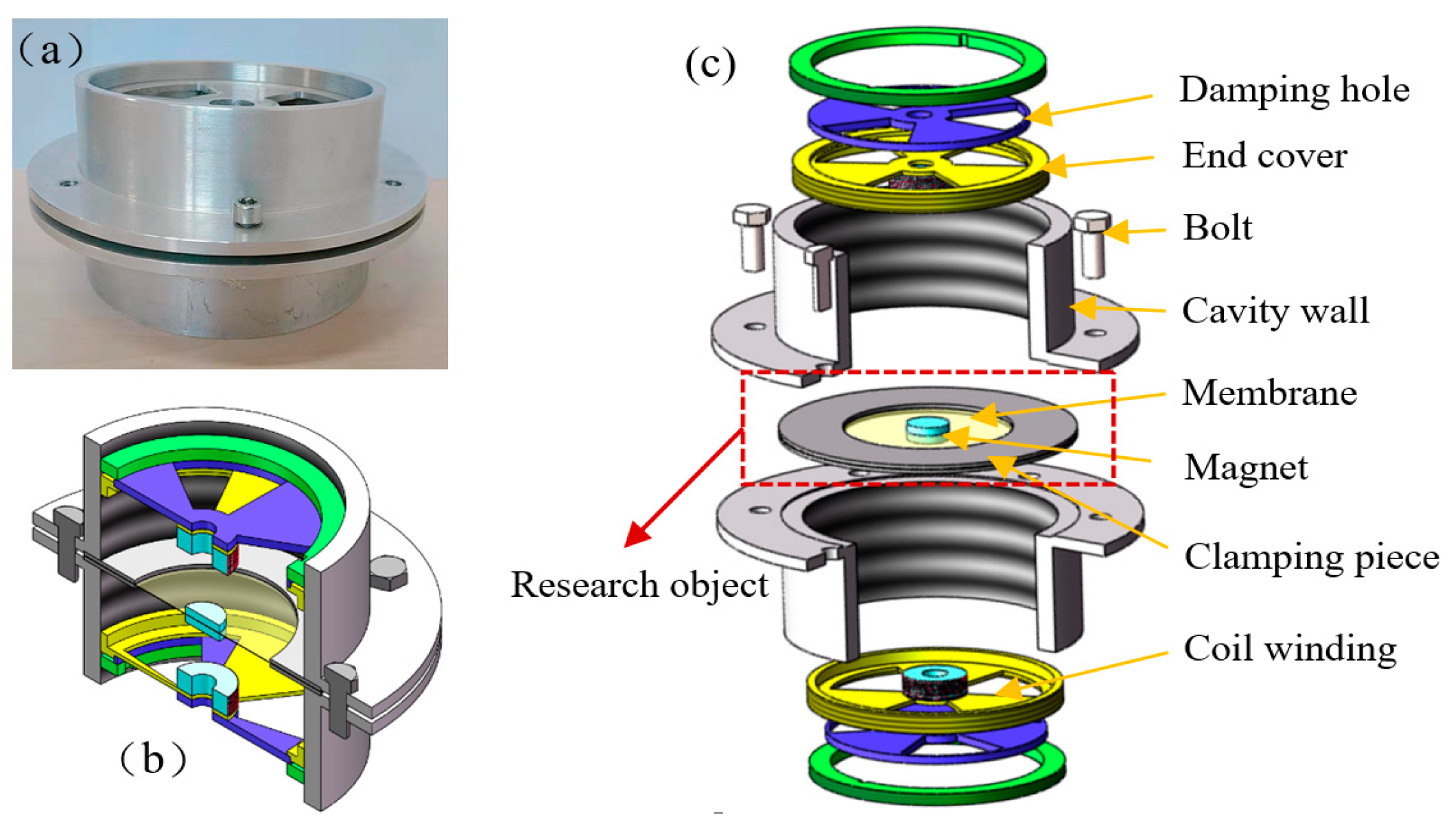
The configuration of BEMH is outlined in Figure 1, which is mainly composed of a membrane, a rigid magnet, two iron coil windings and a cavity wall. The polyimide membrane is bonded to the clamp by epoxy resin, and the NdFeB magnet is adsorbed on both sides of the polyimide membrane. The iron coil windings which are composed of highly conductive enameled wires are fixed to the upper and lower end covers by epoxy resin. The cavity wall is made of non-magnetic aluminum material in order to prevent magnetic leakage from reducing output power. The stiffness of the magnetic spring is adjustable through moving the upper and lower end covers. In addition, it has adjustable sector damping holes which can be used to study the effect of air damping on output power.
The working principle of the BEMH is that the co-axial permanent magnet driven by the membrane vibrates up and down in the cavity wall, which changes the magnetic flux of the conductive coil windings around the upper and lower end covers to generate inductive electromotive force. If the polyimide membrane is replaced by piezoelectric membrane, the energy harvester will become a hybrid vibration energy harvester.
The BEMH studied in this paper can be simplified to the mechanical model shown in Figure 2, which is composed of a membrane surrounding with a co-axial magnet. The membrane radius and thickness are and , respectively. The radius and mass of the magnet are and , respectively.
If the magnetic force is large enough, the effect of co-axis mass gravity on the system can be neglected. The energy harvesting efficiency of the BEMH can be investigated by setting a cosine excitation as a simple representative of the harmonic base motion. Mechanical vibration input for the system is achieved through:
where and are respectively the amplitude and angular frequency of excitation acceleration. To represent the large-amplitude axisymmetric vibrations of the plate, the vibration governing equations are written in the form of Berger equations [45]:
where is bending stiffness of the circular plate. From the stress-strain relations, the time-dependent function may be expressed as , where and represent radial and tangential stress, respectively.
Different from the generally employed Berger equations, in this article, it takes the transverse inertia term, foundation excitation, the mass inertia of the co-axial magnet, the mechanical damping, and the action of the nonlinear magnetic spring into consideration. Considering that the thickness of the membrane is small, the bending stiffness is neglected, i.e., . To describe the forced lateral axisymmetric vibration of a circular membrane with a center magnet, the governing equations can be written in the form like:
where , is the Kronecker delta, is the transverse displacement, is the radial displacement, is the elasticity modulus, is Poisson’s ratio, is the tension of the membrane, is the density of the membrane, and is the damping coefficient.
When the rigid magnet sustains an up-down symmetric transverse vibration, a vertical force is given in Figure 3. The Equations (4) and (5) are subjected to the following boundary conditions:
Based on the cubic nonlinear magnetic force, the magnetic force between magnets and iron cores is expressed as follows [46]:
where and represent the linear stiffness coefficient and the nonlinear stiffness coefficient provided by the magnetic spring, respectively.
Equation (5) can be rewritten in the equivalent form:
Because is only a time-dependent function, one may thus multiply Equation (8) by and integrate from the radius to the outside radius :
When the membrane is clamped, the radial displacement vanishes at the boundaries and . The left side of Equation (9) may be integrated by parts and expressed in the alternate form:
The time-dependent function can be obtained by Equation (10). Based on the standard method of separation of variables, the relative vibration response of the membrane can be separated to the spatial and temporal functions as the following series form:
where is the time-dependent response, and is the i-th mode function of vibration of the membrane.
To investigate the dynamic response of the BEMH system, the natural frequencies of the membrane and associated mode eigenfunction are obtained by the undamped free vibration Equation of the membrane, as follows [47]:
Substituting Equation (11) into Equation (12), the mode function is given by:
The associated boundary conditions can be formulated as:
where is the undamped natural frequency of the th vibration mode, and the eigenvalue of th vibration mode is given by:
Using the differential eigenvalue problem, the eigenfunction is expressed as [48]:
where the coefficient is given by:
Regarding the eigenfunction and the boundary conditions, the eigenequation of the differential eigenvalue problem can be obtained as follows:
It should be noted that, according to the orthogonality conditions, the eigenfunction can be mass normalized and stiffness normalized respectively as followed [49]:
where is the Kronecker delta, and the coefficient can be calculated by using the above orthogonality relations.
Then, substituting Equations (1), (7) and (10) into Equation (4), the distributed parameter model of transverse vibration for the BEMH can be given by:
Substituting Equation (11) into Equation (21), multiplying both sides by and integrating over the radius of the membrane, and considering the orthogonality relations of Equations (19) and (20), the following ordinary differential equation is obtained:
where the parameters in Equation (22) are:
and the mechanical damping ratio of the th mode of vibration can be obtained by experimental measurement and is the equivalent mass of the membrane and the magnet. For large deflection vibration of the membrane, the influence of higher-order nonlinear components on dynamic characteristics of the system should not be neglected. However, the traditional Galerkin discretization method usually ignores the influence of higher-order components, and obtains the lower-order model by its reduction is inaccurate in the case of large-amplitude vibration of the membrane, which will lead to greater deviations in power optimization analysis based on reduced-order model. Therefore, the nonlinear Galerkin method is chosen to reduce the order of the model, considering higher-order nonlinearities when the membrane undergoes large-amplitude vibration.
2.2. Reduced-Order Model
Many practical structures are infinite-dimensional systems, which usually have the characteristics of dense and continuous modes. In order to discuss the vibration of the structures, order reduction methods are often used to obtain a lower-order model but sufficient precision.
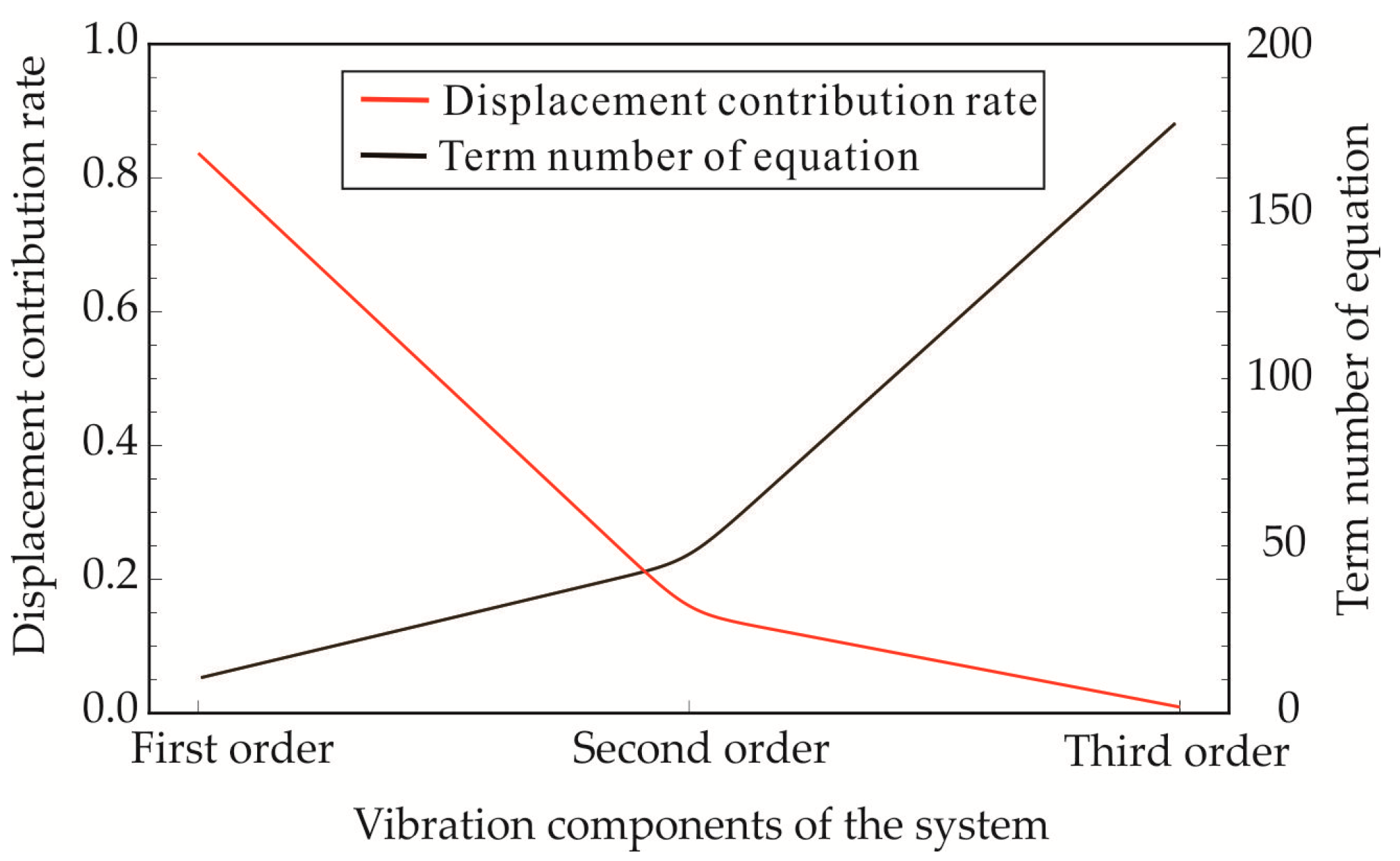
Convergence problem is the primary concern when dealing with continuum model by dimension reduction method. The first three-order vibration modes are intercepted for analysis. As shown in Figure 4, the contribution of the first order component is 84%, the second order component is 14%, and the third order component is only 0.9%. However, the computational complexity is increasing rapidly. To guarantee the accuracy and convergence rate of calculation of the system, the second-order truncation is chosen to calculate and analyze the model.
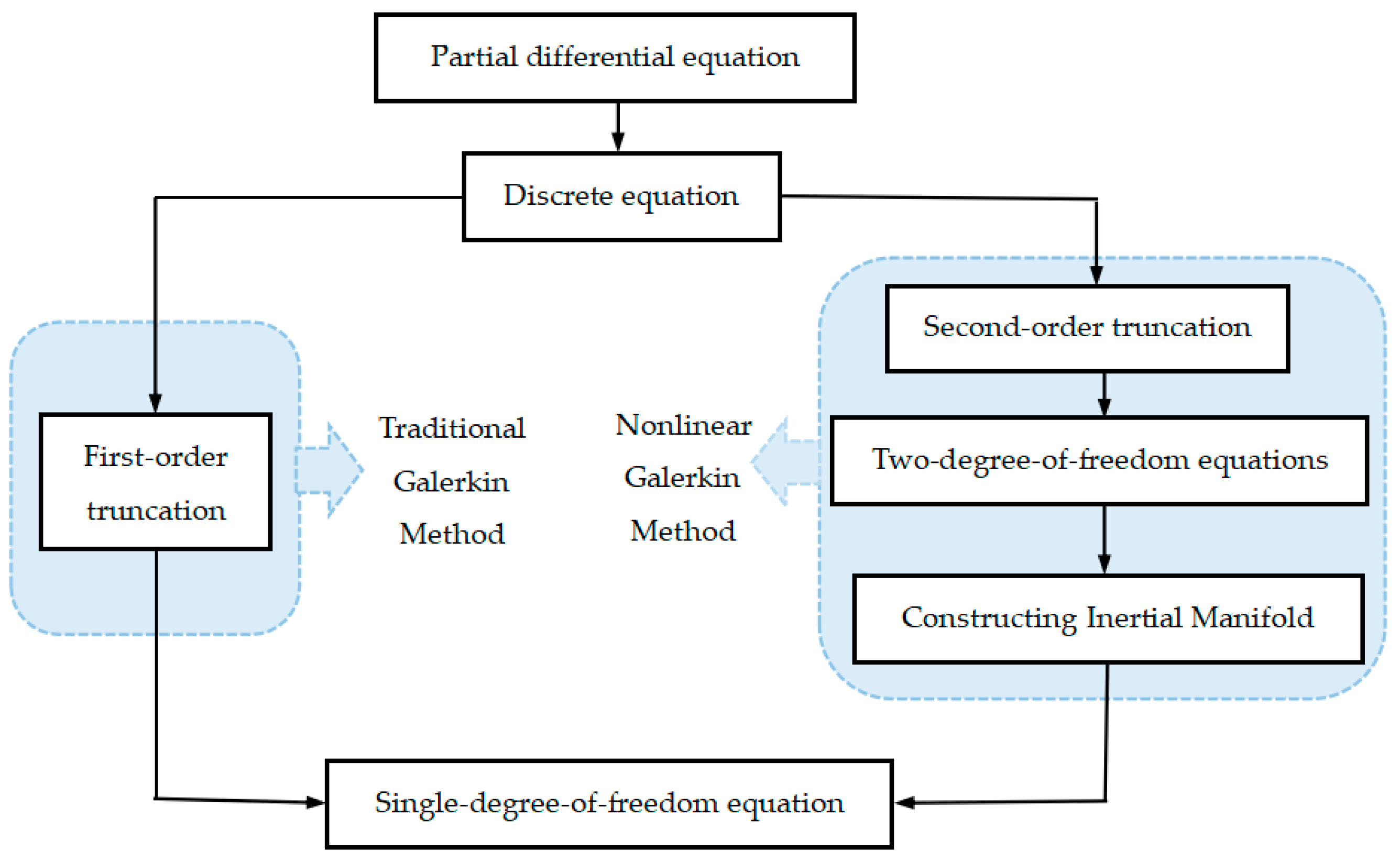
In traditional Galerkin method, the low-order model is often based on experience interception directly, without considering the influence of higher-order components. However, there is a drawback of the direct truncation method, ignoring the higher-order components influences on structure, and getting the imprecise conclusions for a nonlinear system when a large-amplitude vibration occurs. Therefore, Marion and Temam [50] proposed the nonlinear Galerkin method based on the traditional Galerkin method to refine the reduced-model. Referring to the construction of the approximate inertial manifold, the key issue of the nonlinear Galerkin method is to describe the original system with the low-order model and consider the influence of higher-order components in the same order equation. Accordingly, it has higher accuracy and better convergence speed than the traditional method. The major difference between the two methods can be found in the flowchart of Figure 5.
The traditional Galerkin method usually truncates Equation (22) directly to obtain the reduced-order model without considering the influence of higher-order components. For example, when , the reduced-order single-degree-of-freedom (SDOF) system is given by:
In contrast, the reduced-order SDOF equation obtained by nonlinear Galerkin method includes not only lower-order components but also higher-order components of the system. In particular, the higher-order components are taken as second-order modes, i.e., . For , the two-degree-of-freedom differential equations are as follows:
Where and . Equations (25) and (26) can be written in the matrix form as follows:
Where
Equation (27) can be rewritten in the matrix form:
The approximate inertial manifold reflecting the relation between and is solved by means of the fixed point method. Because is a small quantity, considering that the derivative of high frequency components for time is very small, let and , ignoring the second-order and above infinitesimals of , the result is given by:
Substituting Equation (30) into Equation (25), the reduced-order model solved by nonlinear Galerkin method is obtained. Because this SODF equation is very large and complex, it is not listed separately here.
3. Model Validation and Result Analysis
3.1. The Output Displacement Response and Power of the BEMH
The transverse vibration displacement response of the system, that is, the approximate solution of Equation (21) can be obtained by numerical solution of the reduced-order SODF equation as follows:
Involving the electromagnetic damping, the mechanical energy of the vibration system can be converted into electric energy. The instantaneous output power and average output power over one vibration period, transferred from the vibration source to the electromagnetic damping, can be expressed respectively as [51]:
where is the vibration velocity of the magnet, and the electromagnetic damping coefficient can be expressed as:
where is coil resistance, is external resistance, and is the commonly assumed as the electromagnetic coupling constant [52] between the moving magnet and coil windings, which reflects the strength of electromagnetic interaction. Electric power is usually considered to be the output power, which is upon the assumption: .
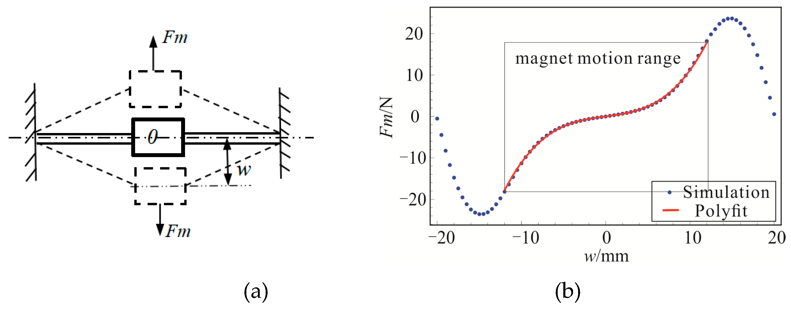
In the structure of the BEMH, the distance between the co-axial magnet and the upper and lower iron cores are variable to adjust the magnetic force on the co-axial magnet by changing the relative position between the upper and lower end covers. The energy harvester is still a monostable system with small magnetic force, and turns to a bistable model as the magnetic force increases to a certain range. Adjusting the stiffness of magnetic spring to keep the system in bistable state and fixing the upper and lower iron cores, the magnetic force of the co-axial levitated magnet is obtained using Ansoft Maxwell software for finite element analysis of the electromagnetic field in this paper. According to the vibration range of the magnet, the magnetic simulation and polynomial fit results are shown in Figure 6.
In order to analyze the vibration response characteristics and the generated electric power across the resistive load of the EBMH under different harmonic excitations, the numerical comparison is carried out for the reduced-order system via the traditional Galerkin method and nonlinear Galerkin method. Then the dynamic characteristics obtained by the mathematical models are comparatively analyzed with the finite element simulation results. In this system, the physical parameters in numerical solution and simulation analysis are designated consulting the entity structure as shown in Table 1.
3.2. Finite Element Simulation Validations and Numerical Results
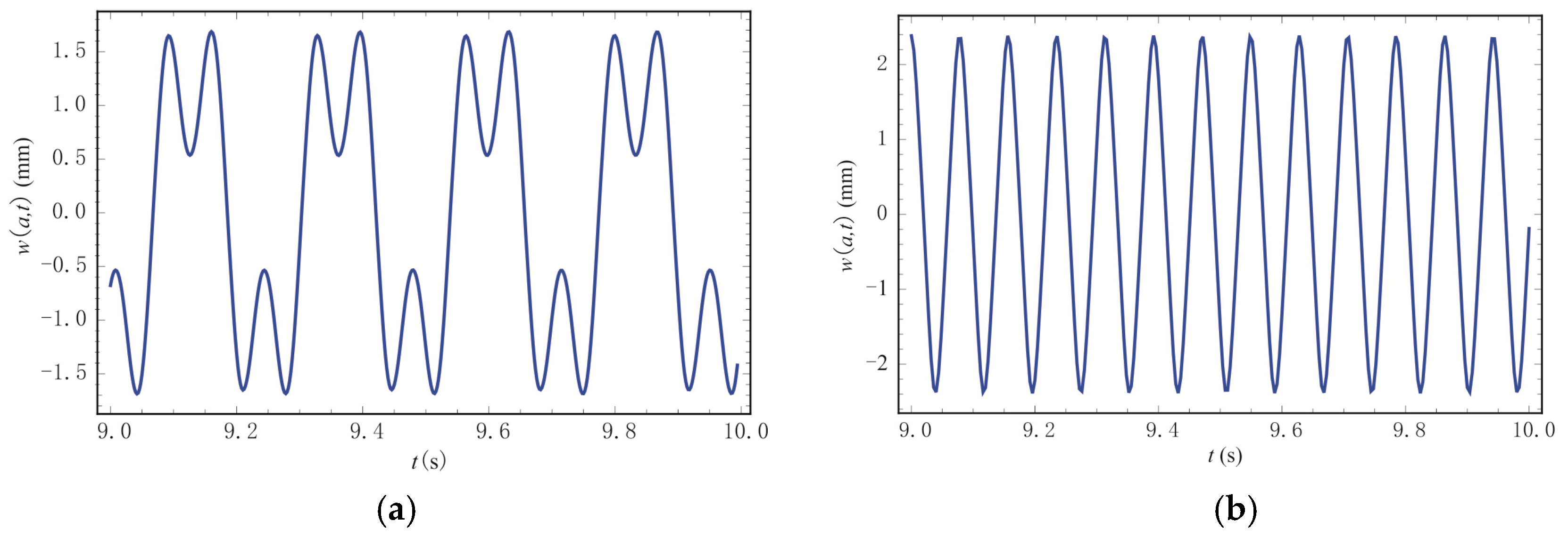
The bifurcation diagram of amplitude-frequency response relation is obtained, calculating the dynamic displacement response of the reduced-order model based on the nonlinear Galerkin method at different frequencies, as shown in Figure 7. Through the dynamic analysis of the theoretical model, we know that under the excitation amplitude of 5 m/s2, the system cannot obtain enough energy at a small excitation frequency. In this stage, the system makes small-amplitude vibration near one of its equilibrium points as shown in Figure 8a. With the increase of excitation frequency, the system gains enough energy from the excitation and begins to transfer from the bistable movement to large-amplitude steady vibration. Among them, the critical frequency value of the bistable movement is 6 Hz as shown in Figure 8b. Then, as the excitation frequency continues to increase, the system begins to vibrate substantially and steadily as shown in Figure 8c. That results verify the low frequency character of the membrane harvester, and the advantage of bistable movement in improving the output performance. Accordingly, the architecture model in this article is very suitable for the common engineering applications.
In order to verify the theoretical model, the finite-element simulation model of the membrane-magnet is established by using the finite-element software ANSYS Workbench. The transient dynamic analysis of the model under different excitation conditions is carried out. The results of vibration response are shown in Figure 9. As the excitation frequency reaches 6 Hz, the system undergoes the bistable vibration. Then, the system generates large-amplitude stable vibration with the increase of excitation frequency.
For the comparison between the results in Figure 8 and Figure 9, the excitation frequency calculated by the mathematical model is basically coherent with the finite-element calculation result, at which the BEMH begins to be the bistable vibration under the same excitation amplitude. When = 6 m/s2 and = 13 Hz, the amplitude of large periodic motion of the system is also similar to the finite-element result. Therefore, the obtained computational dynamics model is effective to analyze the dynamic behavior of the BEMH.
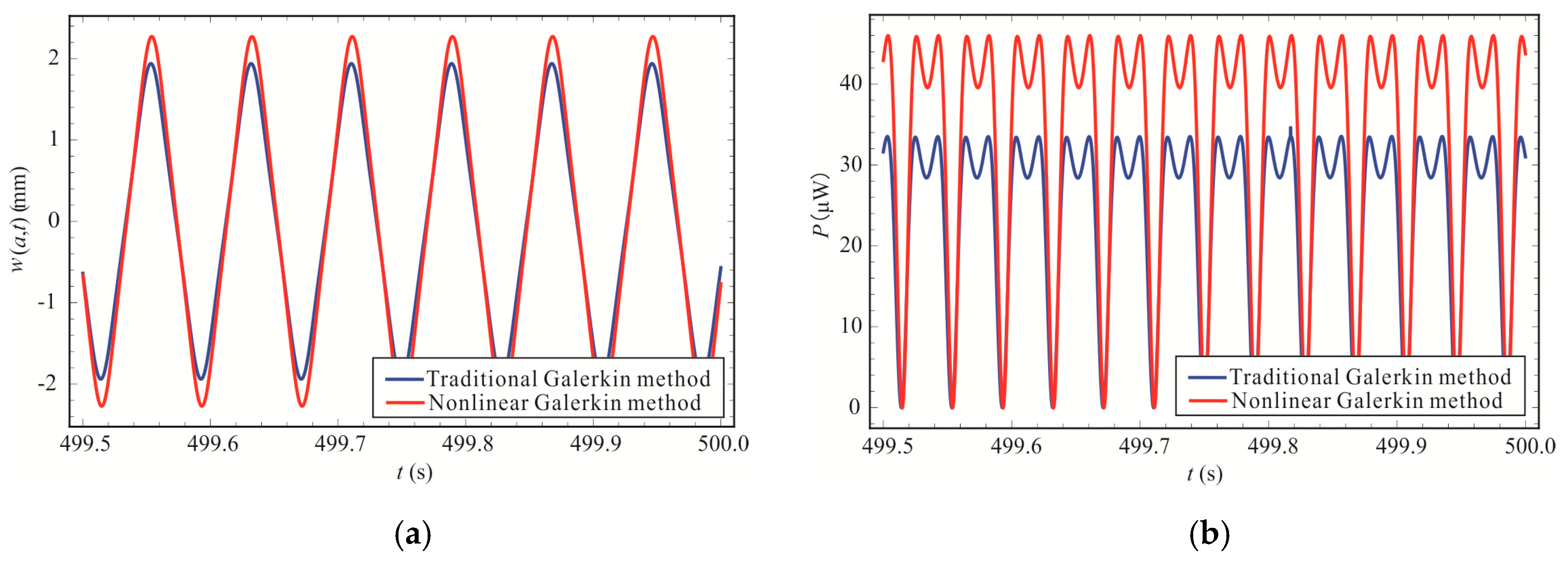
The dynamic characteristics of large-amplitude vibration and power output of the membrane and magnetic spring system are numerically studied by nonlinear Galerkin methods and traditional Galerkin method under same excitation amplitude of 5 m/s2 and frequency of 13 Hz. The BEMH generates large-amplitude and steady vibration under this condition, and the vibration displacement and instantaneous output power of the two models are compared as shown in Figure 10. It is found that the displacement responses and instantaneous output powers of the two models are quite different, and the deviations of instantaneous powers are non-negligible.
Within the excitation frequency range of the large-amplitude and stable vibration of the system, the vibration displacement and average output power are calculated by different methods. Figure 11 shows that the amplitude results obtained by the model of traditional Galerkin method are within 18.5% error of the finite-element simulation results, and the results analyzed by the model of nonlinear Galerkin method is within 4.6% error. Therefore, the calculation model using nonlinear Galerkin method is closer to the finite-element model.
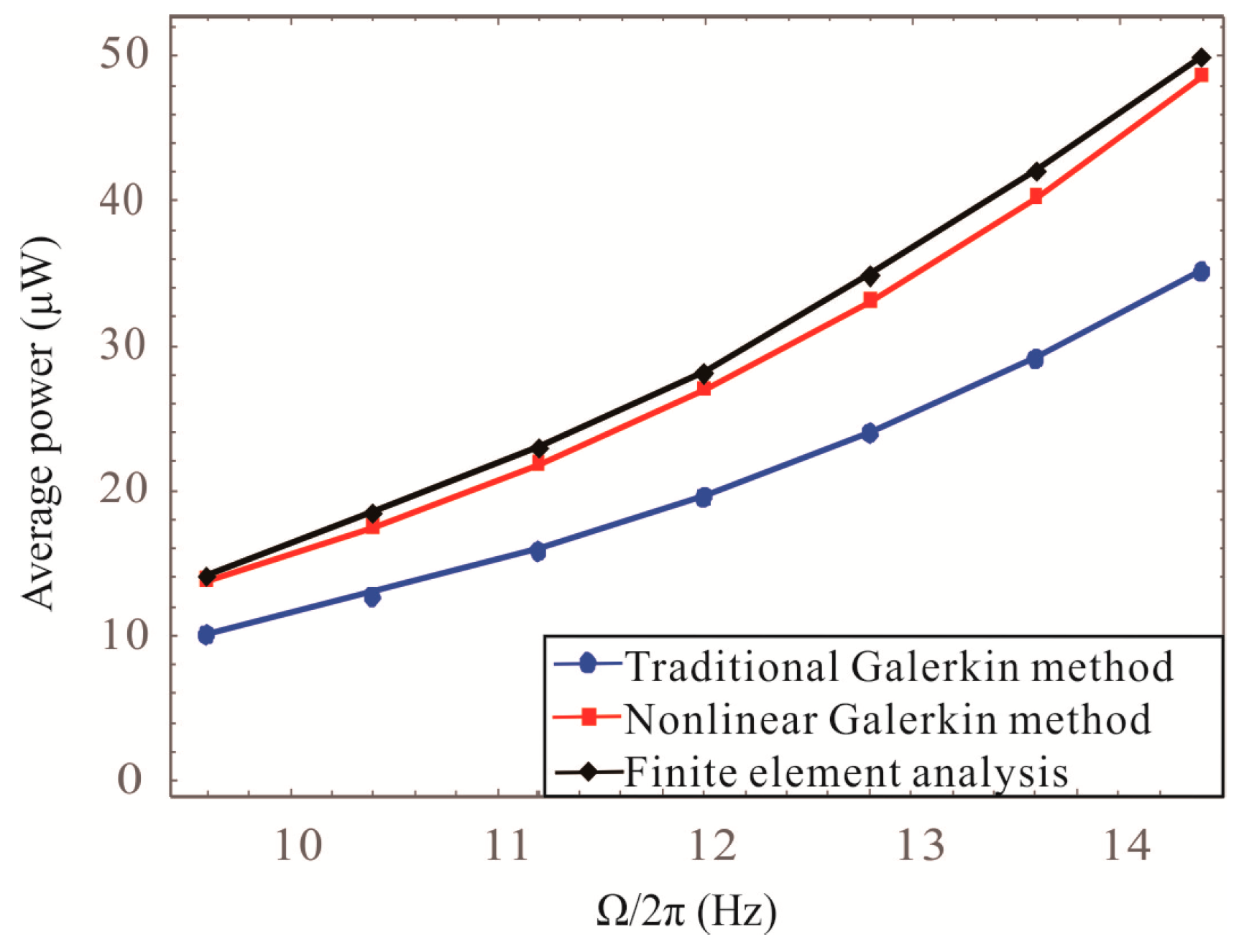
As is shown in Figure 10b, the instantaneous output powers of the BEMH obtained by the model of traditional Galerkin method and nonlinear Galerkin method also have major differences. The average power generated by the BEMH in one vibration period is calculated utilizing three models as shown in Figure 12, in which the maximum calculation errors gained by the models of traditional Galerkin method and nonlinear Galerkin method are 31.1% and 5.4% respectively, compared with the results of the finite-element analysis. In conclusion, the dynamic model reduced via nonlinear Galerkin method is more accurate and available for the dynamic analysis of the large-amplitude vibrations on membrane structures.
3.3. Experimental Results
The main objective of the experiment is to validate the theoretical model and investigate the both quantitative comparison between the theoretical model and qualitative agreement with numerical simulation predictions. The laboratory-scale experimental devices and the prototype of energy harvester as shown in Figure 13 are designed and fabricated, whose geometry property is listed in Table 1. The experimental devices are mainly composed of signal generator (Tektronix AFG3102C), power amplifier (SPEKTRA APS 125), shaker table (SPEKTRA APS 113), laser displacement sensor (KEYENCE 1L-100), charge amplifier (Brüel & Kjær 2692), data acquisition device (Brüel & Kjær 3560B/C/D ), etc. The shaker table is used to provide the periodic excitation, whose value is controlled and monitored by the accelerometer. The output voltage are recorded through the data acquisition device to display on the personal computer.
In the signal generator, the input frequency is 6 Hz, and the voltage is 3 V. According to the previous numerical calculation, the system can produce bistable motion only in a certain interval. Therefore, the gain knob of the signal amplifier makes the amplitude of the sinusoidal motion of the prototype increase from zero until bistable vibration occurs. The amplitude and the frequency of the excitation signal is recorded under bistable vibration. The bistable signal generated by the system is shown in Figure 14. In that case, the power converted from the measured voltage is very close to the theoretical value.
Under different excitation frequencies, the excitation amplitudes are different required for the system to achieve bistable vibration. As can be seen from Table 2, the model obtained by this nonlinear Galerkin method can be used to solve the bifurcation parameters of the system in which the bistable vibration occurs.
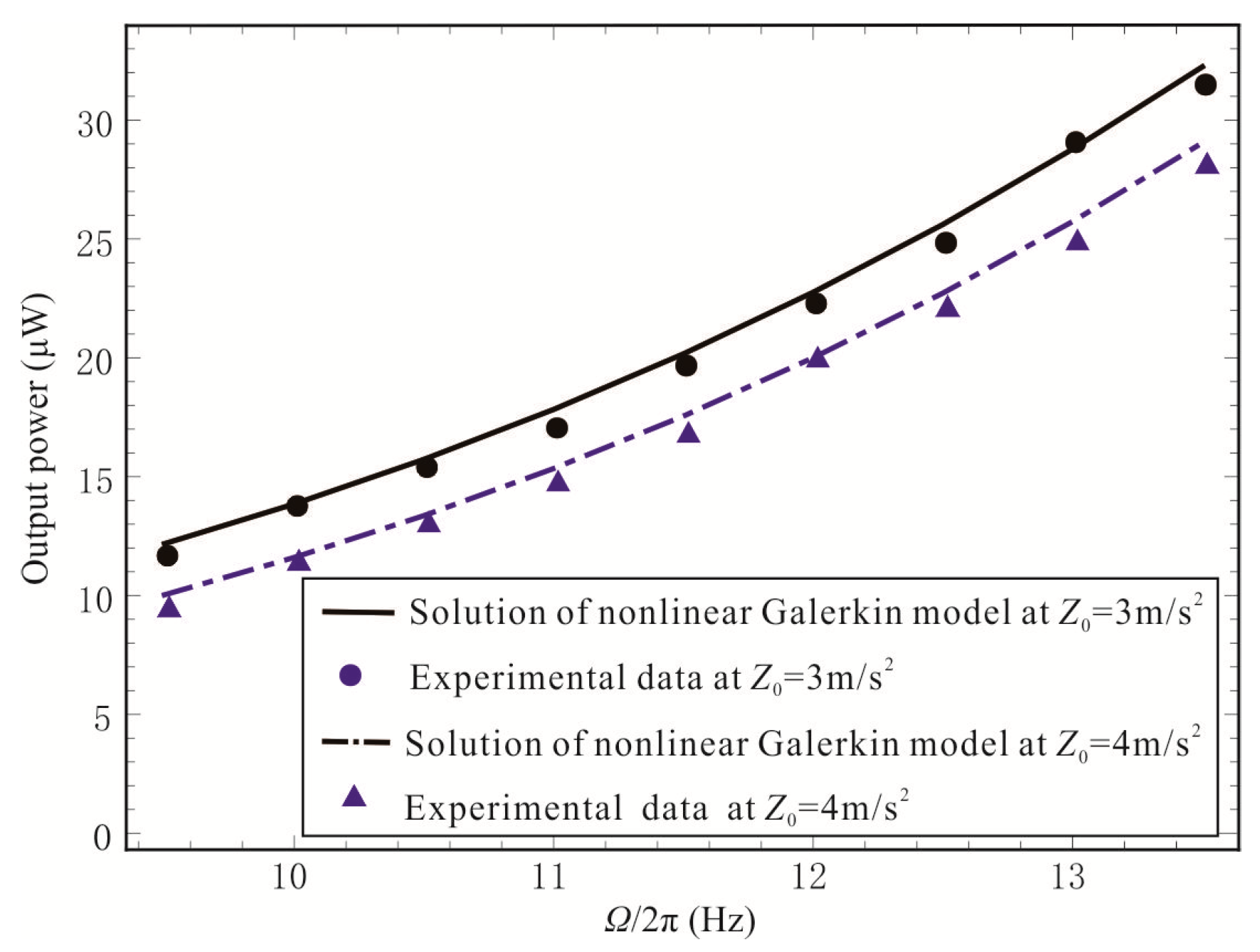
Within the excitation frequency range of the large-amplitude and stable vibration of the system. Figure 15 shows measured output power of the system at two different accelerations, i.e., 3 m/s2 and 4 m/s2, respectively. It also compares the higher-order nonlinear model predictions of output power against measured data. In general, at both accelerations, 3 m/s2 and 4 m/s2, experiment and mathematical model show similar trends.
4. Parametric Study of the BEMH
With the validated model of the nonlinear Galerkin method, further numerical computations are performed to reveal the vibration response and average output power of the BEMH under periodic excitations. Amongst other factors, structure radius ratio and membrane thickness affect more significantly on the dynamic response of the system in the vibration of a circular membrane with a co-axis mass [53]. This paper mainly concerns the changing rules of the corresponding amplitude and the output power with the variation of these two parameters. When the parameters of the center magnet are determined, the radius ratio a/b of the system can be adjusted by changing the radius of the membrane structure.
Figure 16 and Figure 17 show that under the same excitation condition, the amplitude and average output power of the BEMH decrease with the increase of the radius ratio. Especially, when radius ratios are 0.05 to 0.1, the amplitude and average output power of the BEMH change significantly. Then the change is relatively slower when the radius ratio is greater than 0.1. In addition, with the radius ratio of 0.05, the system has a maximum error of 30.7% in amplitude and 52.9% in average power through comparing the calculated results of the two models. Furthermore, the resulted error decreases with the increase of the radius ratio.
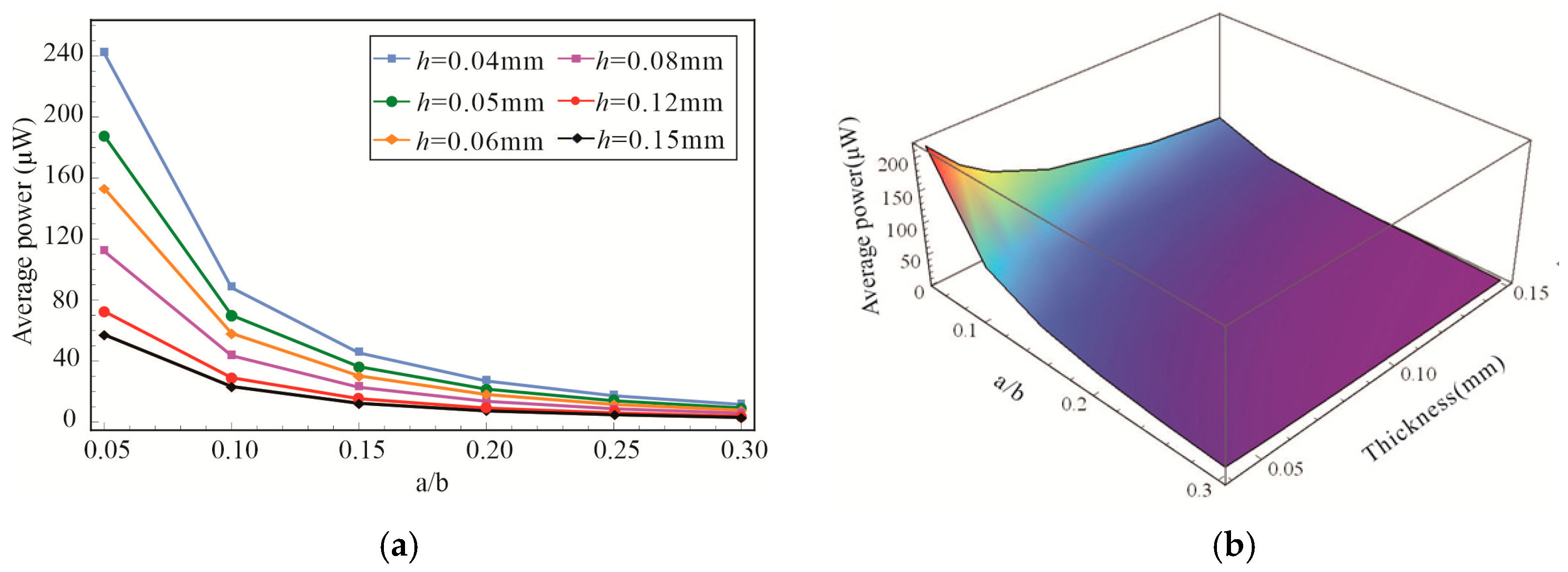
Additionally, the thickness of the membrane also affects the vibration response and the average output power of the BEMH. As shown in Figure 18 and Figure 19, both the vibration amplitude and the average output power will decrease with the increase of membrane thickness. In the change of radius ratios from 0.05 to 0.3, the analysis results have the largest decline with the membrane thickness of 0.04 mm that the amplitude falls by up to 75.3% and the average power reduces by 93.3%. In the change of membrane thickness from 0.04 mm to 0.12 mm, the analysis results have the largest decline with the radius ratio of 0.05 that the amplitude falls by up to 49.8% and the average power reduces by 74.3%. When the radius ratio is 0.3, the influence of membrane thickness on the output power of energy harvesting system is negligible. To sum up, the BEMH model acquired by nonlinear Galerkin method leads to more accurate results. Moreover, the output power of the energy harvester can be improved by decreasing the radius ratio of the structure and the membrane thickness, which provides a theoretical reference for optimizing the structure parameters.
5. Conclusions
In this paper, a novel architecture of BEMH is proposed to collect the mechanical energy characterized by low frequency and small amplitude environmental vibration. The nonlinear distributed parameter model is established for the large deflection transverse vibration membrane attached with a co-axial magnet mass. The low-order vibration equation is obtained via the nonlinear Galerkin method to cope up with the higher-order geometrical and magnetic nonlinearities. It provides an efficient foundation for considering the influence of higher-order nonlinearity, such as the nonlinearity caused by the geometric deformation of large-amplitude vibration or nonlinear magnetic force. Accordingly, the vibration characteristics and output power of the system under different excitation conditions can be accurately analyzed, thus providing an efficient theoretical basis to optimize the power output performance of the BEMH. The conclusions are as follows:
1. The proposed BEMH can harvest low-frequency and small-amplitude vibration energy in a broad bandwidth. It can carry out bistable vibration, thereby increasing the vibration displacement and improving the efficiency of energy acquisition.
2. By taking the higher-order components as second-order modes via the nonlinear Galerkin method, the model order is reduced, which allows the model to be solved efficiently. Moreover, the nonlinear Galerkin method gives a solution both close agreeable with that of FE result and experiment data.
3. With this efficient and accurate approach, it has been verified that both the radius ratio and the membrane thickness show a significant improvement on the output power with a lower value. The influence of the membrane thickness on output power is negligible when the radius ratio reaches a certain value. This finding provides a theoretical basis for designing the structure in order to obtain a higher power output.
Author Contributions
Conceptualization, W.W.; Data curation, B.Z.; Formal analysis, B.Z.; Funding acquisition, Q.Z. and W.W.; Investigation, X.T.; Methodology, B.Z. and J.H.; Project administration, Q.Z. and W.W.; Resources, B.Z., F.G. and A.D.B.; Software, J.H.; Supervision, Q.Z., W.W. and A.D.B.; Validation, B.Z.; Visualization, B.Z.; Writing—original draft, B.Z.; Writing—review & editing, Q.Z., W.W., J.H., X.T. and F.G..
Funding
This research was funded by the National Natural Science Foundation of China, grant 11872044, 11772218 and 11702192; the International Exchanges Cost Share 2018 China (NSFC-RS) award (IEC\NSFC\181496); the Tianjin Research Programme of Application Foundation and Advanced Technology grant 17JCYBJC18900 and the National Key Research and Development Program of China grant 2018YFB0106200.
Conflicts of Interest
The authors declare no conflict of interest.
References
- Ranjith, B.; Halder, P.; Samad, A. High-performance ocean energy harvesting turbine design—Detailed flow analysis with blade leaning strategy. Proc. Inst. Mech. Eng. Part A J. Power Energy 2018, 233, 379–396. [Google Scholar] [CrossRef]
- White, A.J.; McTigue, J.D.; Markides, C.N. Analysis and optimisation of packed-bed thermal reservoirs for electricity storage applications. Proc. Inst. Mech. Eng. Part A J. Power Energy 2016, 230, 739–754. [Google Scholar] [CrossRef]
- Qiu, Q.; Xiao, L.Y.; Xin, S.Q.; Huang, T.B. Research progress of vibration micro-generator. J. Vib. Shock 2010, 29, 191–195. [Google Scholar]
- Yen, K.T. Energy Collection of Autonomous Sensor System: Design, Analysis and Practical Application; China Machine Press: Beijing, China, 2014. [Google Scholar]
- Chang, S.; Wang, Q.; Hu, H.; Ding, Z.; Guo, H. An NNwC MPPT-Based Energy Supply Solution for Sensor Nodes in Buildings and Its Feasibility Study. Energies 2019, 12, 101. [Google Scholar] [CrossRef]
- Gunduz, D.; Stamatiou, K.; Michelusi, N.; Zorzi, M. Designing Intelligent Energy Harvesting Communication Systems. IEEE Commun. Mag. 2014, 52, 210–216. [Google Scholar] [CrossRef]
- Akbari, S. Energy Harvesting for Wireless Sensor Networks Review. Com. SIS Consortium 2014, 2, 987–992. [Google Scholar]
- Elvin, N.G.; Elvin, A.A. Vibrational Energy Harvesting From Human Gait. IEEE/ASME Trans. Mechatron. 2013, 18, 637–644. [Google Scholar] [CrossRef]
- Orphée, C.; Jérôme, D.; Raisigel, H. Permanent magnet planar micro-generators. Sens. Actuators A Phys. 2006, 30, 438–444. [Google Scholar]
- Abdelmoula, H.; Sharpes, N.; Abdelkefi, A.; Lee, H.; Priya, S. Low-frequency Zigzag energy harvesters operating in torsion-dominant mode. Appl. Energy 2017, 204, 413–419. [Google Scholar] [CrossRef]
- Cooley, C.G. Vibration properties of and power harvested by a system of electromagnetic vibration energy harvesters that have electrical dynamics. Mech. Syst. Sig. Process. 2017, 94, 237–252. [Google Scholar] [CrossRef] [Green Version]
- Truong, B.D.; Le, C.P.; Halvorsen, E. Analysis of Electrostatic Energy Harvesters Electrically Configured as Bennet’s Doublers. IEEE Sens. J. 2017, 17, 5180–5191. [Google Scholar] [CrossRef]
- Wang, C.; Zhang, Q.C.; Wang, W. Low-frequency wideband vibration energy harvesting by using frequency up-conversion and quin-stable nonlinearity. J. Sound Vib. 2017, 399, 169–181. [Google Scholar] [CrossRef]
- Wu, Y.P.; Ji, H.L.; Qiu, J.H.; Zhang, H. Nonlinear piezoelectric vibration energy harvester with the adjustable resonance frequency. J. Vib. Shock 2017, 36, 12–16. [Google Scholar]
- Li, H.T.; Qin, W.Y.; Deng, W.Z.; Lan, H.B.; Tian, R.L. Dynamics and coherent resonance of composite bistable energy acquisition system. J. Vib. Shock 2016, 35, 119–124. [Google Scholar]
- 16 Yao, M.H.; Li, Y.B.; Zhang, W. Nonlinear dynamics of longitudinal auxiliary magnetism bistable piezoelectric cantilever beam. J. Beijing Univ. Technol. 2015, 41, 1756–1760. [Google Scholar]
- Naifar, S.; Bradai, S.; Viehweger, C.; Kanoun, O. Survey of electromagnetic and magnetoelectric vibration energy harvesters for low frequency excitation. Measurement 2017, 106, 251–263. [Google Scholar] [CrossRef]
- Zhu, D.; Beeby, S.; Tudor, J.; Harris, N. Increasing output power of electromagnetic vibration energy harvesters using improved Halbach arrays. Sens. Actuators A Phys. 2013, 203, 11–19. [Google Scholar] [CrossRef] [Green Version]
- Ayala-Garcia, I.N.; Mitcheson, P.D.; Yeatman, E.M.; Zhu, D.; Tudor, J.; Beeby, S.P. Magnetic tuning of a kinetic energy harvester using variable reluctance. Sens. Actuators A Phys. 2013, 189, 266–275. [Google Scholar] [CrossRef]
- Abdelmoula, H.; Zimmerman, S.; Abdelkefi, A. Accurate modeling, comparative analysis, and performance enhancement of broadband piezoelectric energy harvesters with single and dual magnetic forces. Int. J. Nonlinear Mech. 2017, 95, 355–363. [Google Scholar] [CrossRef]
- Spreemann, D.; Manoli, Y. Electromagnetic Vibration Energy Harvesting Devices. Advanced Microelectronics; Springer: Berlin/Heidelberg, Germany, 2012. [Google Scholar]
- Zhang, L.B.; Abdelkefi, A.; Dai, H.L.; Naseer, R.; Wang, L. Design and experimental analysis of broadband energy harvesting from vortex-induced vibrations. J. Sound Vib. 2017, 408, 210–219. [Google Scholar] [CrossRef]
- Zhu, J.; Wang, A.; Hu, H.; Zhu, H. Hybrid Electromagnetic and Triboelectric Nanogenerators with Multi-Impact for Wideband Frequency Energy Harvesting. Energies 2017, 10, 2024. [Google Scholar] [CrossRef]
- Huang, D.; Zhou, S.; Litak, G. Theoretical analysis of multi-stable energy harvesters with high-order stiffness terms. Commun. Nonlinear Sci. 2019, 69, 270–286. [Google Scholar] [CrossRef]
- Naseer, R.; Dai, H.L.; Abdelkefi, A.; Wang, L. Piezomagnetoelastic energy harvesting from vortex-induced vibrations using monostable characteristics. Appl. Energy 2017, 203, 142–153. [Google Scholar] [CrossRef]
- Yan, B.; Zhou, S.; Litak, G. Nonlinear Analysis of the Tristable Energy Harvester with a Resonant Circuit for Performance Enhancement. Int. J. Bifurcation Chaos. 2018, 28, 1850092. [Google Scholar] [CrossRef]
- Zhou, S.; Cao, J.; Litak, G.; Lin, J. Numerical analysis and experimental verification of broadband tristable energy harvesters. Tm-Tech. Mess 2018, 85, 521–532. [Google Scholar] [CrossRef]
- Daqaq, M.; Masana, R.; Erturk, A.; Quinn, D.D. Closure: On the Role of Nonlinearities in Energy Harvesting: A Critical Review and Discussion. Appl. Mech. Rev. 2014, 66, 046001. [Google Scholar] [CrossRef]
- Dhakar, L.; Liu, H.; Tay, F.E.H.; Lee, C. A new energy harvester design for high power output at low frequencies. Sens. Actuators A Phys. 2013, 199, 344–352. [Google Scholar] [CrossRef]
- Paula, A.S.D.; Inman, D.J.; Savi, M.A. Energy harvesting in a nonlinear piezomagnetoelastic beam subjected to random excitation. Mech. Syst. Sig. Process. 2015, 54–55, 405–416. [Google Scholar] [CrossRef]
- Zhou, S. Harmonic balance analysis of nonlinear tristable energy harvesters for performance enhancement. J. Sound Vib. 2016, 373, 223–235. [Google Scholar] [CrossRef]
- Mann, B.P.; Owens, B.A. Investigations of a nonlinear energy harvester with a bistable potential well. J. Sound Vib. 2010, 329, 1215–1226. [Google Scholar] [CrossRef]
- Kremer, D.; Liu, K. A nonlinear energy sink with an energy harvester: Transient responses. J. Sound Vib. 2014, 333, 4859–4880. [Google Scholar] [CrossRef]
- Harne, R.L.; Thota, M.; Wang, K.W. Bistable energy harvesting enhancement with an auxiliary linear oscillator. Smart Mater. Struct. 2013, 22, 125028. [Google Scholar] [CrossRef]
- Fan, K.; Tan, Q.; Liu, H.; Zhang, Y.; Cai, M. Improved energy harvesting from low-frequency small vibrations through a monostable piezoelectric energy harvester. Mech. Syst. Sig. Process. 2019, 117, 594–608. [Google Scholar] [CrossRef]
- Mofidian, S.M.M.; Bardaweel, H. A dual-purpose vibration isolator energy harvester: Experiment and model. Mech. Syst. Sig. Process. 2019, 118, 360–376. [Google Scholar] [CrossRef]
- Wang, C.; Zhang, Q.; Wang, W.; Feng, J. A low-frequency, wideband quad-stable energy harvester using combined nonlinearity and frequency up-conversion by cantilever-surface contact. Mech. Syst. Sig. Process. 2018, 112, 305–318. [Google Scholar] [CrossRef]
- Man, X.B.; Wu, X.H.; Sun, Q. Research on order reduction of flexible beam model by nonlinear Galerkin method. J. Xi’an Jiaotong Univ. 2015, 49, 113–119. [Google Scholar]
- Mirkhalaf, M.; Najafizadeh, M.M. Vibration analysis of circular plates with an eccentric circular perforation with a free edge and attached concentrate. Aust. J. Basic Appl. Sci. 2016, 12, 3052–3058. [Google Scholar]
- Lin, W.J.; Chen, S.H. Finite element analysis of transverse vibration of membranes. J. Appl. Mech. 2011, 28, 44–49. [Google Scholar]
- Rubin, M.B.; Nadler, B. An Eulerian Formulation for Large Deformations of Elastically Isotropic Elastic-Viscoplastic Membranes. J. Mech. Mater. Struct. 2016, 11, 197–216. [Google Scholar] [CrossRef]
- Yamada, S.; Ijima, K.; Obiya, H.; Zakaria, M.N.; Abd Rahman, N.; Mohd Jaini, Z.; Yunus, R.; Rahmat, S.N. An Orthotropic Membrane Model for the Large Deformation Analysis and Snapping Phenomena of the Dome Inflated. MATEC Web Conf. 2016. [Google Scholar] [CrossRef]
- Hansbo, P.; Larson, M.G.; Larsson, F. Tangential differential calculus and the finite element modeling of a large deformation elastic membrane problem. Comput. Mech. 2015, 56, 87–95. [Google Scholar] [CrossRef]
- Nguyen, C.H.; Halvorsen, E. Harmonic-Balance Analysis of Nonlinear Energy Harvester Models. In Proceedings of the IEEE International Symposium on Circuits and Systems (ISCAS), Melbourne, VIC, Australia, 1–5 June 2014. [Google Scholar]
- Berger, H.M. A new approach to the analysis of large deflections of plates. Ph.D. thesis, California Institute of Technology, Pasadena, California, 1954. [Google Scholar]
- Pennisi, G.; Mann, B.P.; Naclerio, N.; Stephan, C.; Michon, G. Design and experimental study of a Nonlinear Energy Sink coupled to an electromagnetic energy harvester. J. Sound Vib. 2018, 437, 340–357. [Google Scholar] [CrossRef]
- Zheng, Z.L.; Guo, J.J.; Song, W.J.; He, X.T.; Lu, F.M.; Xie, C.X.; Sun, J.Y. Nonlinear free vibration analysis of axisymmetric polar orthotropic circular membranes under the fixed boundary condition. Math. Prob. Eng. 2014, 651356. [Google Scholar] [CrossRef]
- Wang, C.Y. Vibration of an annular membrane attached to a free, rigid core. J. Sound Vib. 2003, 260, 776–782. [Google Scholar] [CrossRef]
- Alper, E.; Daniel, J.I. Piezoelectric Energy Harvesting; National Defense Industry Press: Beijing, China, 201; pp. 308–312. [Google Scholar]
- Marion, M.; Temam, R. Nonlinear Galerkin methods: The finite elements case. Numer. Math. 1990, 57, 205–226. [Google Scholar] [CrossRef]
- Alevras, P.; Theodossiades, S.; Rahnejat, H. On the dynamics of a nonlinear energy harvester with multiple resonant zones. Nonlinear Dyn. 2018, 92, 1271–1286. [Google Scholar] [CrossRef] [Green Version]
- Priya, S.; Inman, D.J. Energy Harvesting Technologies; Spring US: New York, NY, USA, 2009; pp. 84–89. [Google Scholar]
- Soares, R.M.; Gonçalves, P.B. Nonlinear vibrations and instabilities of a stretched hyperelastic annular membrane. Int. J. Solids Struct. 2012, 49, 514–526. [Google Scholar] [CrossRef] [Green Version]
Figure 1.
Schematic diagram of the BEMH: (a) assembly diagram; (b) profile; (c) internal structure diagram.
Figure 1.
Schematic diagram of the BEMH: (a) assembly diagram; (b) profile; (c) internal structure diagram.

Figure 2.
Mechanical model of the BEMH.
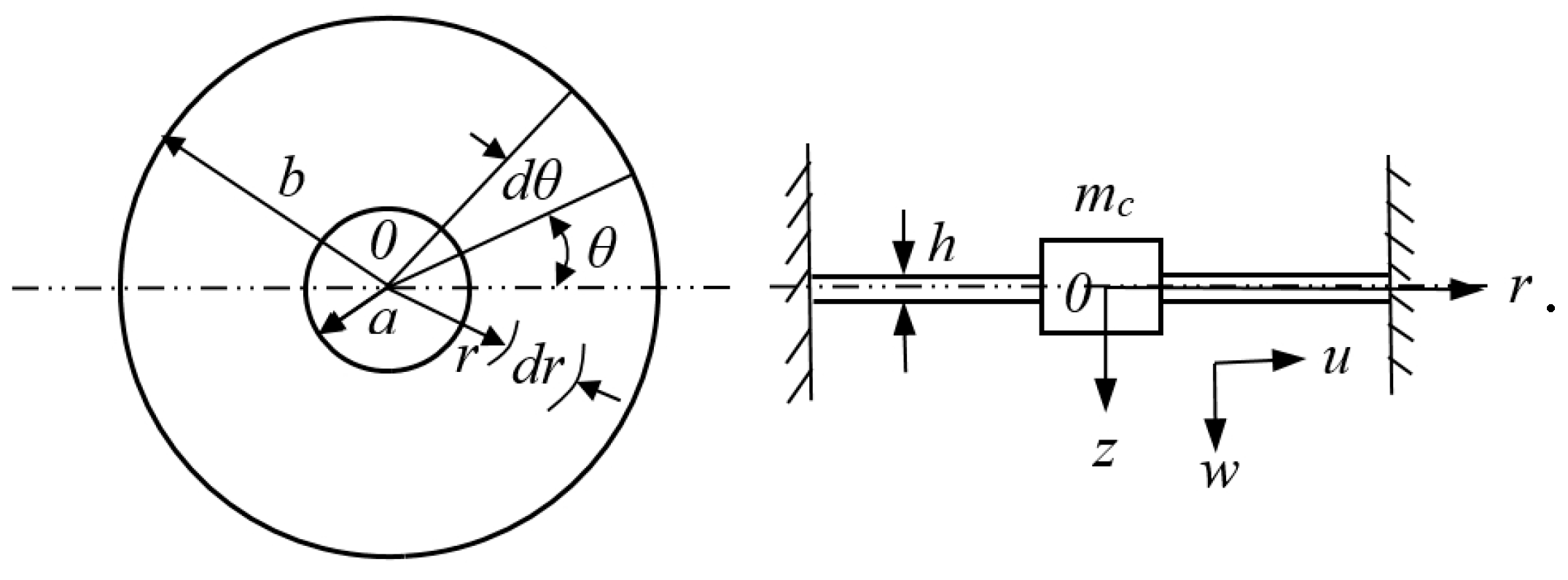
Figure 3.
The circular membrane with a rigid magnet and forces in symmetric vibration.
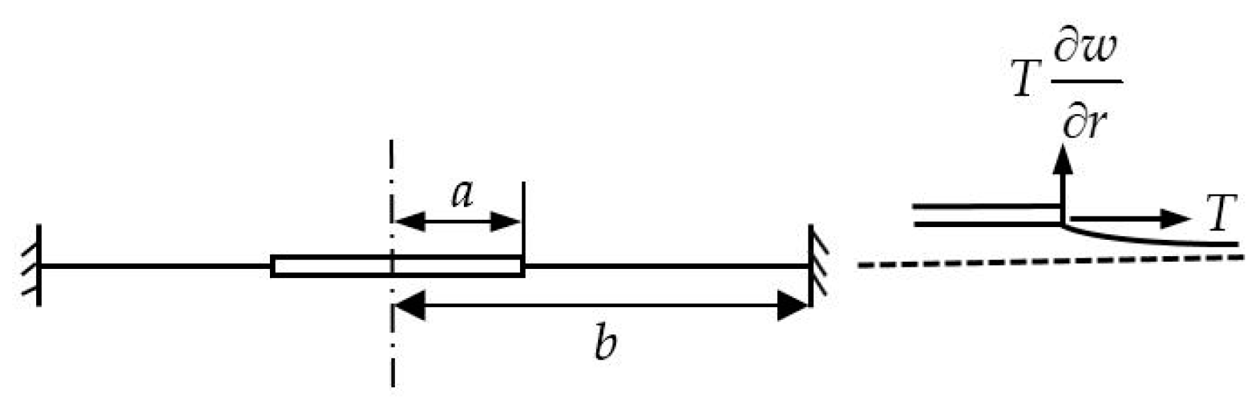
Figure 4.
Analysis results of third-order modal truncation.

Figure 5.
The difference between two methods of dimension reduction.

Figure 6.
(a) The vibration range of the magnet; (b) Magnetic curve of the magnet.

Figure 7.
The bifurcation diagram of amplitude-frequency response relation.
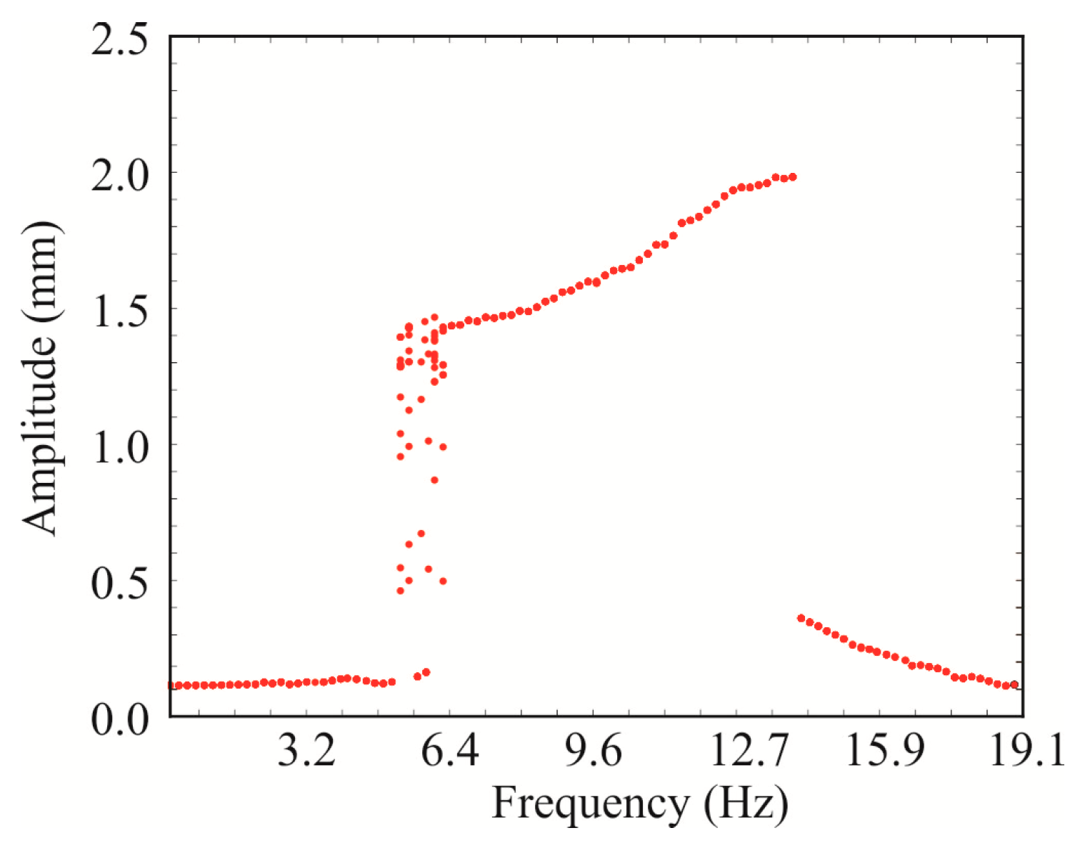
Figure 8.
Time-displacement curve and phase diagram of the system at Z0 = 5 m/s2: (a) = 5 Hz; (b) = 6 Hz; (c) = 13 Hz.
Figure 8.
Time-displacement curve and phase diagram of the system at Z0 = 5 m/s2: (a) = 5 Hz; (b) = 6 Hz; (c) = 13 Hz.
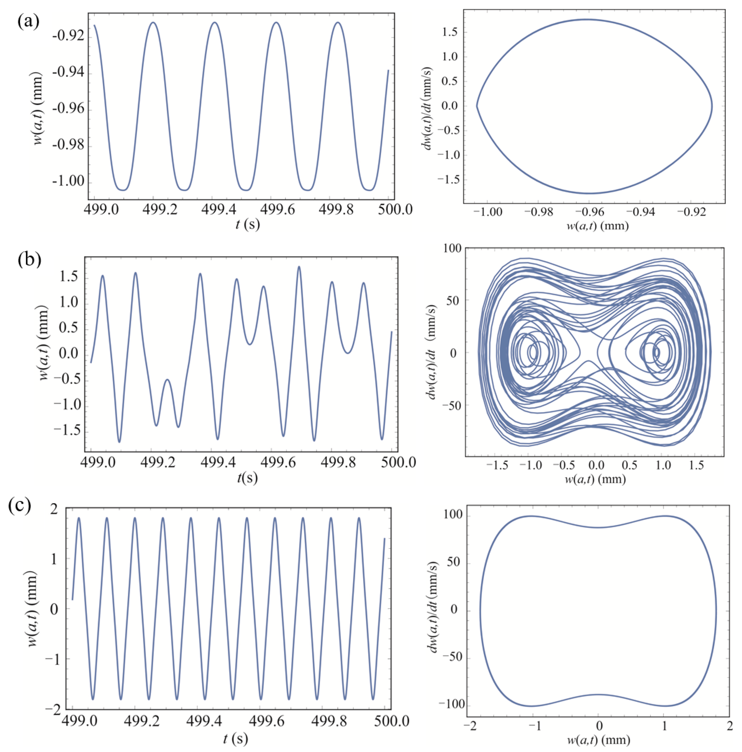
Figure 9.
Dynamic response of the system under different excitations at Z0 = 5 m/s2: (a) = 6 Hz; (b) = 13 Hz.
Figure 9.
Dynamic response of the system under different excitations at Z0 = 5 m/s2: (a) = 6 Hz; (b) = 13 Hz.

Figure 10.
The displacement curve (a) and the instantaneous output power (b) of the BEMH.

Figure 11.
The amplitude of the BEHM under different excitation frequencies.
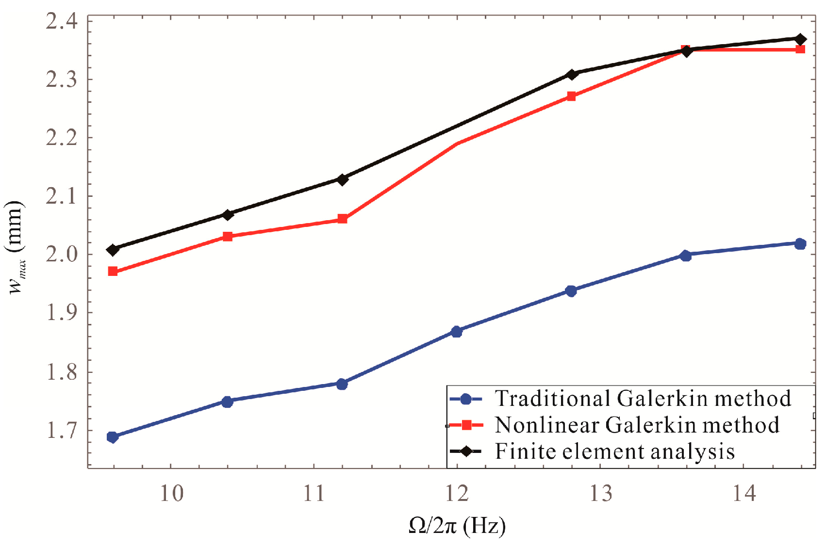
Figure 12.
The average output power of the BEHM under different excitation frequencies.

Figure 13.
Schematic of experimental apparatus of the BEMH.
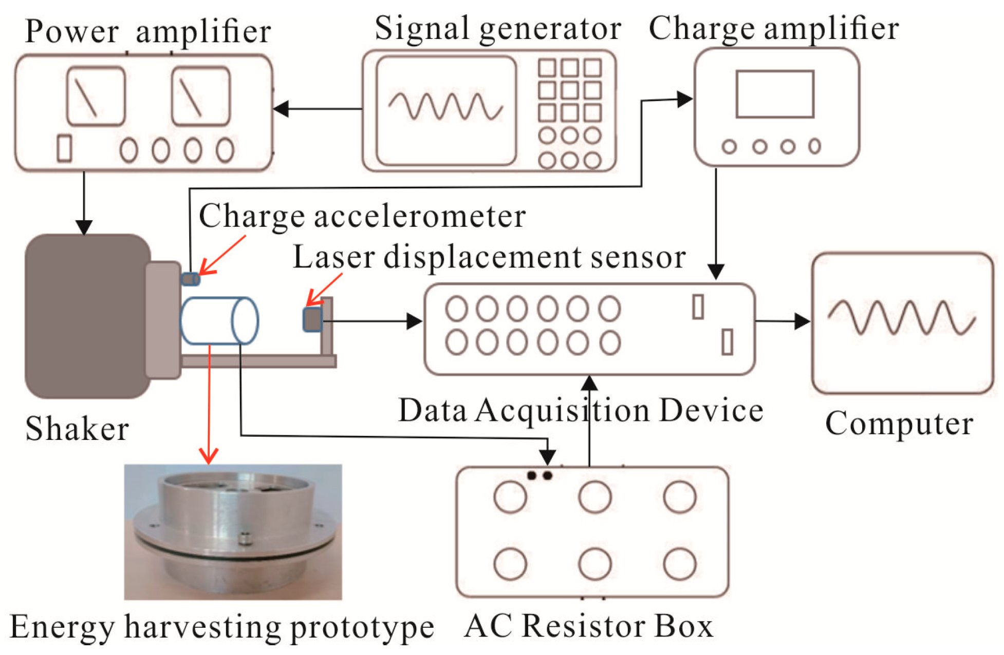
Figure 14.
The bistable signal.
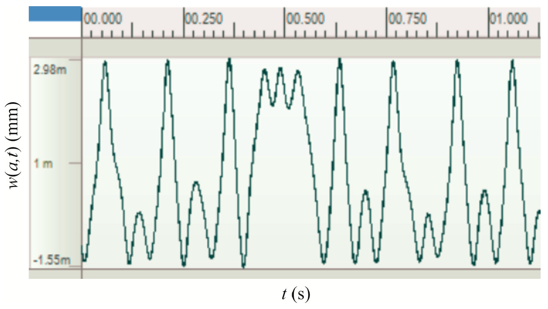
Figure 15.
The output power of system at = 3 m/s2 and = 4 m/s2 obtained from experiment and the model.
Figure 15.
The output power of system at = 3 m/s2 and = 4 m/s2 obtained from experiment and the model.

Figure 16.
The amplitude of the BEMH under different radius ratios.
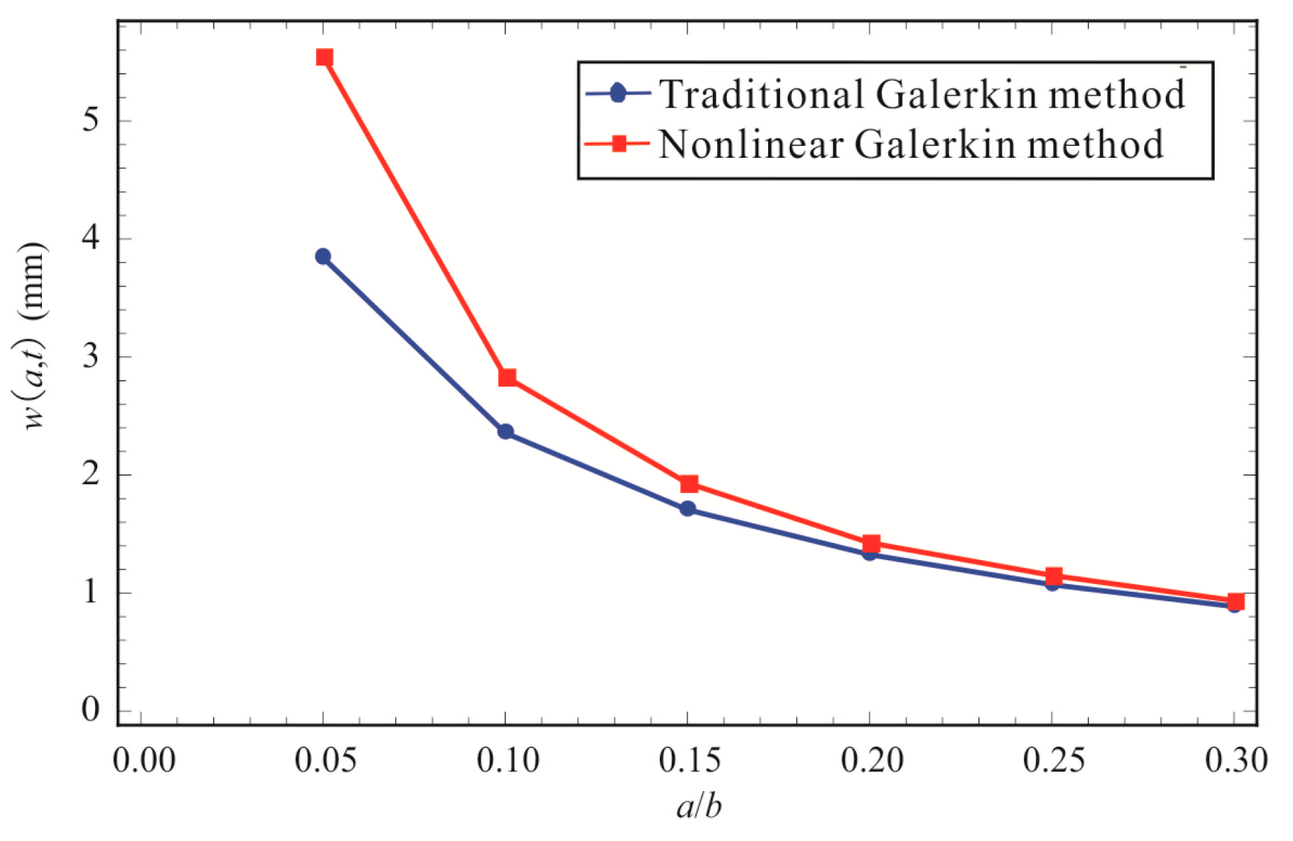
Figure 17.
The power output of the BEMH under different radius ratios.

Figure 18.
The amplitude of the BEMH under different membrane thicknesses and radius ratios: (a) two-dimensional graph; (b) three-dimensional graph.
Figure 18.
The amplitude of the BEMH under different membrane thicknesses and radius ratios: (a) two-dimensional graph; (b) three-dimensional graph.
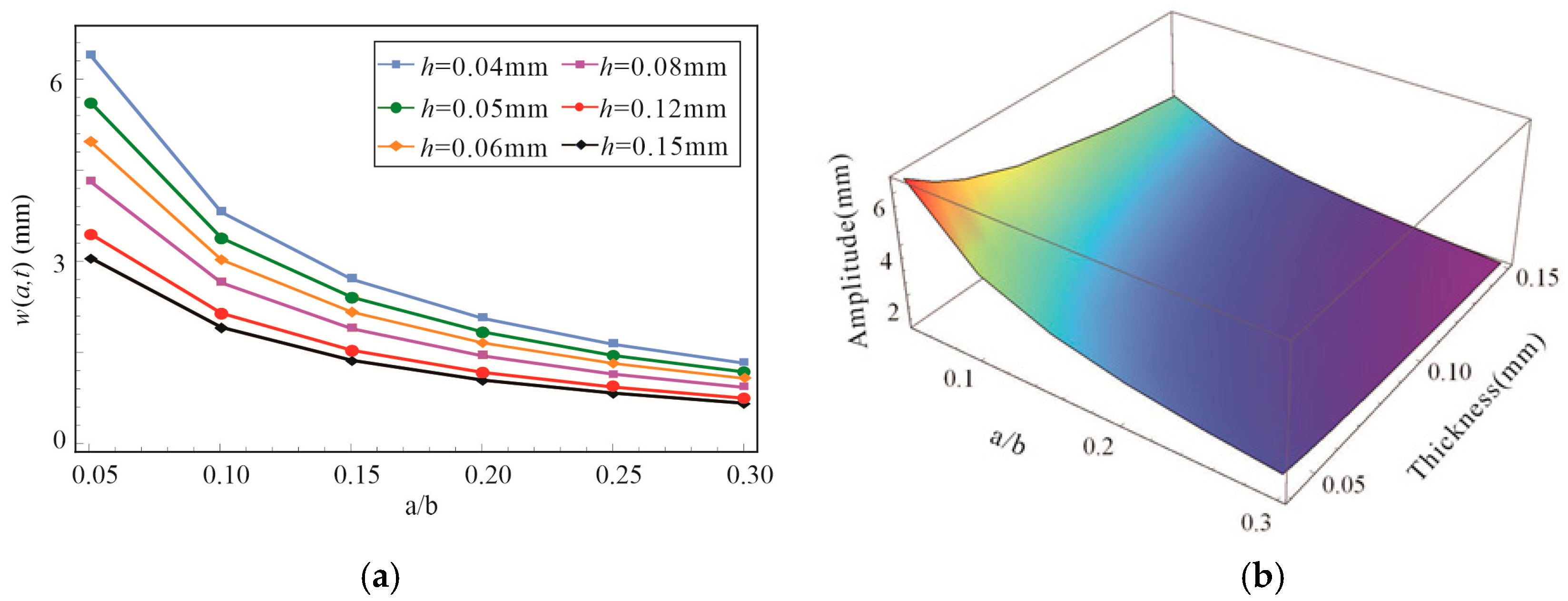
Figure 19.
The power output of the BEMH under different membrane thicknesses and radius ratios: (a) two-dimensional graph; (b) three-dimensional graph.
Figure 19.
The power output of the BEMH under different membrane thicknesses and radius ratios: (a) two-dimensional graph; (b) three-dimensional graph.

Table 1.
Physical parameters of the BEMH.
| Parameters | Symbol | Values |
|---|---|---|
| Radius of center magnet | 7.5 mm | |
| Radius of membrane | 60 mm | |
| Thickness of membrane | 0.05 mm | |
| Mass of center magnet | 10.6 × 10⁻³ Kg | |
| Density of membrane | 1420 Kg/m3 | |
| Elasticity modulus | 90 MPa | |
| Poisson’s ratio | 0.3 | |
| Tension of membrane | 1 N/m | |
| Linear stiffness coefficient | 2.700 N/mm | |
| Nonlinear stiffness coefficient | 8.432 × 10⁻³ N/mm3 | |
| Damping ratio | 0.011 | |
| Electromagnetic coupling coefficient | 6.68 Vs/m | |
| Load resistance | 20 KΩ | |
| Coil resistance | 8.2 Ω |
Table 2.
Excitation amplitude of bistable vibration.
| Excitation Frequency (Hz) | Excitation Maximum Value of Model Prediction (m/s2) | Excitation Maximum Value of Experiment (m/s2) |
|---|---|---|
| 8 | 6.9 | 7.1 |
| 9 | 4.6 | 4.9 |
| 10 | 2.7 | 2.8 |
© 2019 by the authors. Licensee MDPI, Basel, Switzerland. This article is an open access article distributed under the terms and conditions of the Creative Commons Attribution (CC BY) license (http://creativecommons.org/licenses/by/4.0/).
Share and Cite
MDPI and ACS Style
Zhang, B.; Zhang, Q.; Wang, W.; Han, J.; Tang, X.; Gu, F.; Ball, A.D. Dynamic Modeling and Structural Optimization of a Bistable Electromagnetic Vibration Energy Harvester. Energies 2019, 12, 2410. https://doi.org/10.3390/en12122410
AMA Style
Zhang B, Zhang Q, Wang W, Han J, Tang X, Gu F, Ball AD. Dynamic Modeling and Structural Optimization of a Bistable Electromagnetic Vibration Energy Harvester. Energies. 2019; 12(12):2410. https://doi.org/10.3390/en12122410
Chicago/Turabian StyleZhang, Bei, Qichang Zhang, Wei Wang, Jianxin Han, Xiaoli Tang, Fengshou Gu, and Andrew D. Ball. 2019. "Dynamic Modeling and Structural Optimization of a Bistable Electromagnetic Vibration Energy Harvester" Energies 12, no. 12: 2410. https://doi.org/10.3390/en12122410
Note that from the first issue of 2016, this journal uses article numbers instead of page numbers. See further details here.