Springback Coefficient Research of API X60 Pipe with Dent Defect

School of Civil Engineering and Architecture, Southwest Petroleum University, Chengdu 610000, China
*
Author to whom correspondence should be addressed.
Energies 2018, 11(11), 3213; https://doi.org/10.3390/en11113213
Submission received: 10 October 2018
/
Revised: 7 November 2018
/
Accepted: 13 November 2018
/
Published: 20 November 2018
Abstract
:Dent is a common form of defect on oil and gas pipeline. Some dents will undergo elastic or plastic recovery due to changes in internal pressure, also known as springback. To analyze the springback law of an API X60 pipeline with a dent defect, the secondary development technology of finite element software ABAQUS was used for parametric modeling of a dented pipeline. Using this model, the effects of various factors (wall thickness, internal pressure, indenter size, dent location, and dent depth) on the springback coefficient of a dented pipeline were analyzed. The significance of each factor was analyzed by combining an orthogonal experimental design with the Grey correlation degree. Finally, nonlinear regression analysis was used to obtain formulas for the springback coefficient as a function of the influential factors. The results show that the springback coefficient of the dented pipeline after pressurization was between 0.15 and 0.65, and the factor that had the largest effect on the springback coefficient was the dent location. The springback coefficient of the dented pipeline after de-pressurization was between 1.1 and 1.5, and the factor that had the largest effect on the springback coefficient was the internal pressure. The formulas that relate the springback coefficient and various influential factors can be used as a reference for estimating the springback of dented pipelines.
1. Introduction
Since the beginning of the 21st century, the oil and gas industry in China has been developing rapidly. In 2017, natural gas consumption per capita in China increased to 169.7 cubic meters, while oil consumption per capita increased to 0.43 tons [1]. If such a large oil and gas demand is to be satisfied, safe and reliable pipeline transportation is necessary [2]. However, during the installation of pipelines and their prolonged use, pipeline accidents happen frequently. Every year, about 20–40% of pipeline accidents are related to mechanical damage, most commonly in the form of dents [3]. Under the loads of internal pressure, an unconstrained dent located 240° from the topmost point of the pipe circumferential direction (8-4 points clockwise) will spring back, which can affect the prediction of the fatigue life of the pipeline [4,5]. The stress concentration coefficient of the dented pipeline depends on the dent depth, which is affected by the springback behavior of the dent [6,7].
Some literature, institutions, and standards have described the springback behavior of a dented pipeline. ASME 831.8-2014 [8] states that a dent on a weld endangers the pipeline when the dent depth is greater than 2% of the pipe diameter, and measures should be taken to repair it. If the dent depth on the weld exceeds 4% of the pipe diameter, the pipe segment where the dent is located must be removed. The results of the dent test in API 1156-1997 [9] indicated that for a single and unconstrained smooth dent, the amount of springback after unloading was about 2/3. However, this result was only for a dent on a pipe with a diameter to thickness ratio exceeding 68. In addition, API 1156-1997 also provided the springback coefficient under different operating conditions. When the operating pressure was greater than or equal to 70% of the maximum permissible pressure, the springback coefficient was 1.43; otherwise, the springback coefficient was 1. The Battle Institute of the United States [10] proposed an empirical method for calculating the springback coefficient, which only considered the effects of internal pressure and not all the factors that were expected to be relevant. The European Gas Pipeline Accident Data Organization [11] defined the springback coefficient of a plain dented pipeline after the internal pressure was unloaded to be 1.43. PDAM (Pipeline Defect Assessment Manual) [12] suggested that 10% of the pipe diameter is the critical depth of an unconstrained dent on a pipe at zero pressure, which was also the critical depth for a constrained dent on a pipe under pressure. The critical depth of an unconstrained dent on a pipe under pressure was suggested to be 7% of the pipe diameter. Sha et al. [13] selected an X65 steel pipeline for full-scale dent springback tests to study the relationship between dents of different types and the springback. The test results combined with the results of field excavation verification were compared to analyze the disparities in the amounts of springback. Yang et al. [14] established a finite element model of a dented pipeline and qualitatively studied the relationship between the dent depth, internal pressure, and springback. W Hanif et al. [15] adopted a finite element method to investigate the springback of a pipeline with a dent-corrosion defect and to calculate the stress concentration factors of the pipeline. A L Bastard et al. [16] adopted finite element and experimental methods to analyze the springback of a secondary pressurized dented pipe. Various factors (dent size, pipe size, and internal pressure) were considered to develop a springback coefficient formula. J H Baek et al. [17] investigated a dented pipe under internal pressure and in-plane bending by finite element analysis. The effects of the indenter size and internal pressure on the springback behavior were qualitatively analyzed based on finite element results.
The above studies have illustrated the springback behavior of a dented pipe under different conditions. However, to the best of the authors’ knowledge, most of the literature and specifications only consider the effects of dent depth and internal pressure on dent springback, ignoring the influence of other factors. Therefore, this research was focused on the springback behavior of an API 5L X60 dented pipeline under different parameters using finite element analysis. In addition, an orthogonal experimental design combined with the Grey relational degree was used to analyze the significance of influential factors. Finally, nonlinear regression analysis was carried out to fit the relationship between the springback coefficient and parameters.
2. Material
Tensile tests of API 5L X60 steel specimens were carried out by a universal testing machine. The stresses and strains obtained by uniaxial tensile tests were engineering stresses and strains. The true stresses and strains were calculated by the following formula [18]
where εtrue is the true strain, ε is the engineering strain, σtrue is the true stress, and σ is the engineering stress.
3. Parametric Finite Element Analysis
It is necessary to continually modify and reconstruct the model when simulating the springback of a dented pipe, which is burdensome. ABAQUS secondary development technology can effectively solve such problems [19]. The ABAQUS/CAE interface was bypassed by calling the library function through the Python language to achieve automated modeling, meshing, and other processes, which simplified the workflow, saved time and effort, and ultimately improved work efficiency [20].
3.1. Finite Element Model
One quarter of the pipe was established as an analytical model because of the symmetry of the pipe and load condition [21]. To avoid the influence of the end structure of the pipe on the results, the length of the pipe model was set to be three times the pipe diameter [22]. A rigid ellipsoid model was chosen as the indenter model. A 1/2 indenter model was used because of the symmetry. The long and short axes of the ellipsoid are denoted b and a, respectively. The indenters were used to create dents on the pipe with a/b values of 0.1, 0.3, 0.5, and 0.7 (b = 200 mm). Dent depths of 15.24, 20.32, 25.4, 30.48, 35.56, 40.64, 45.72, and 50.8 mm were introduced to the pipe with a diameter of 508 mm and wall thicknesses of 6.9, 7.7, 8.5, and 9.3 mm.
The pipe and indenters with locations of 0°, 30°, 60°, and 90° are shown in Figure 2. A dent was generated for internal pressures of 2, 4, 6, and 8 MPa. A surface-to-surface contact condition with no friction was imposed between the pipe and the indenter [23]. A master surface was defined at the outer surface of the indenter, and the outside surface of the pipe was assigned as a slave surface in the contact analysis [17]. The rigid indenter was divided by free meshing. A local mesh refinement was carried out on the dent area because the dent area of the pipeline was the focus of the analysis. A loose mesh was adopted far from the dent area [24]. Dense meshes with 5 elements through the thickness were assigned by a C3D8R solid element on the dented pipe [25].
3.2. Load Model and Boundary Condition
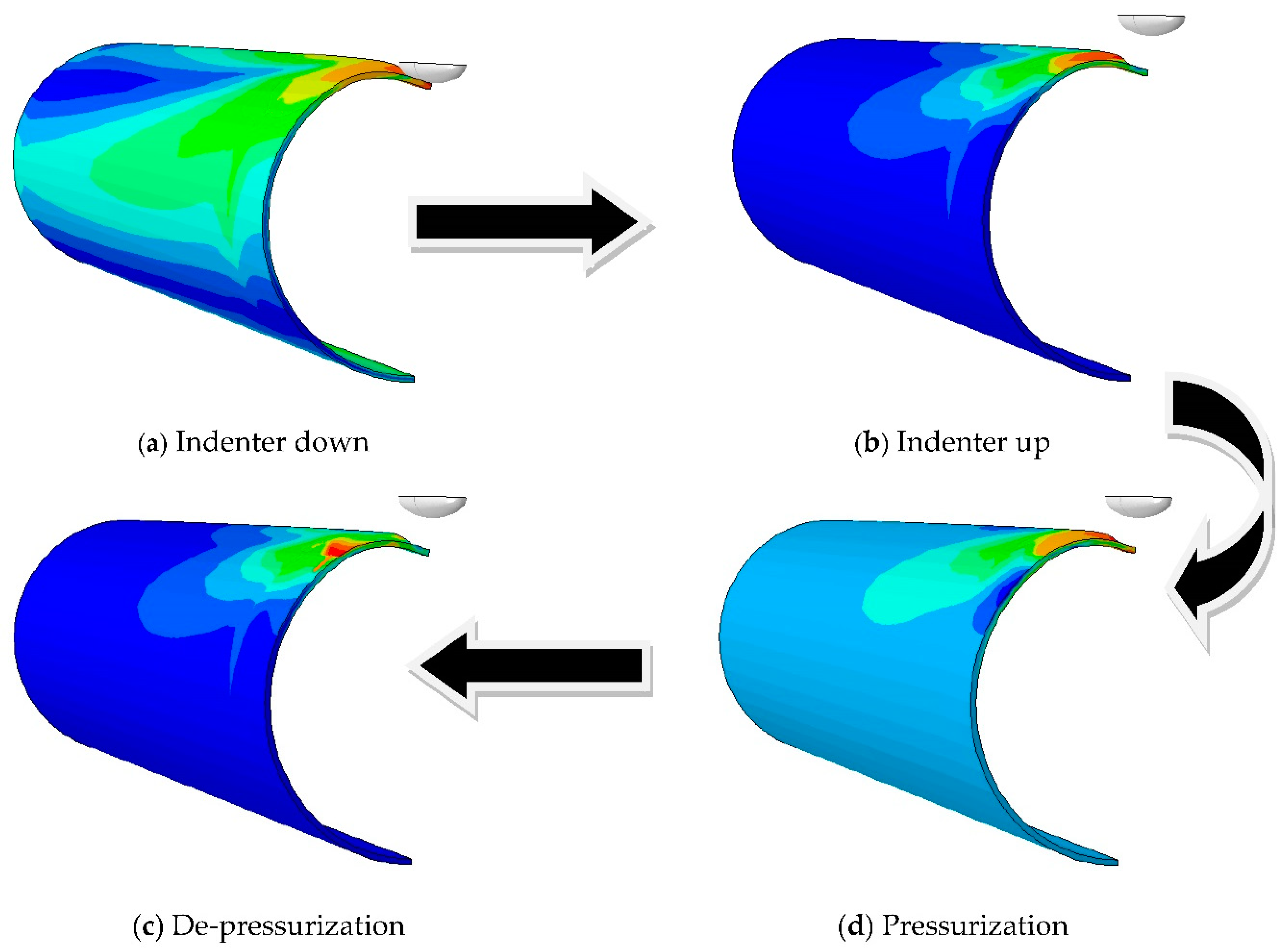
The 120° range of the bottom of the pipe model was restrained in the Y direction [26]. Symmetrical constraints were applied to the proximal boundary and symmetric boundary of the pipeline. The Z direction constraints were assigned to the distal boundary of the pipeline model [27]. Introducing the dent to the pipe was achieved through the following procedure. The analysis steps are shown in Figure 3.
- (1)
- The indenter was applied with a displacement load to simulate the extrusion of the pipe by an external object.
- (2)
- The indenter was applied with a reverse displacement load to simulate the process of removing the external object after the pipe was dented.
- (3)
- An internal pressure was assigned to the inner surface of the pipe to simulate the dented pipe under normal operation.
- (4)
- The internal pressure was released to evaluate the residual dent depth and observe the springback phenomenon.
3.3. Plug-In Program
The parametric analysis plug-in of the dented pipe was created using the RSG dialog builder. The plug-in mainly involved three program files (xxDB.py, xx.py, xx_plugin.py), in which xxDB.py created programs for the dialog interface, xx.py called programs for parameter input, and xx_plugin.py registered programs for the plug-in [20]. The parameterized plug-in was integrated into ABAQUS after successful registration, and the “Dented Pipe Parameterized Analysis Plug-in” appeared in the ABAQUS submenu. The analysis process was entered after entering or modifying the parameters in the parameterized analysis interface.
3.4. FE Model Verification
To ensure that the plug-in program was operating correctly and to verify the accuracy of the finite element model, the full-scale springback test results of a dented oil pipeline in the literature [13] were compared with the numerical simulation results. Figure 4 shows the dent springback test device.
The API 5L X65 pipe with no internal pressure possessed an outer diameter of 820 mm, a wall thickness of 9.5 mm, and length of 11,500 mm. The indenter was a hemisphere with radius of 200 mm. Dent depths of 28, 51, and 106 mm were generated by the indenter. The test parameters were input into the plug-in to establish the model. The comparison between the finite element results and the test results is shown in Figure 5. The finite element results agreed with the test results. Thus, the finite element model was adequate for studying springback in dented pipelines.
4. Results and Discussion
The dent depth changed after pressurizing or releasing pressure. Therefore, the springback coefficient was calculated by:
4.1. Pipe Wall Thickness
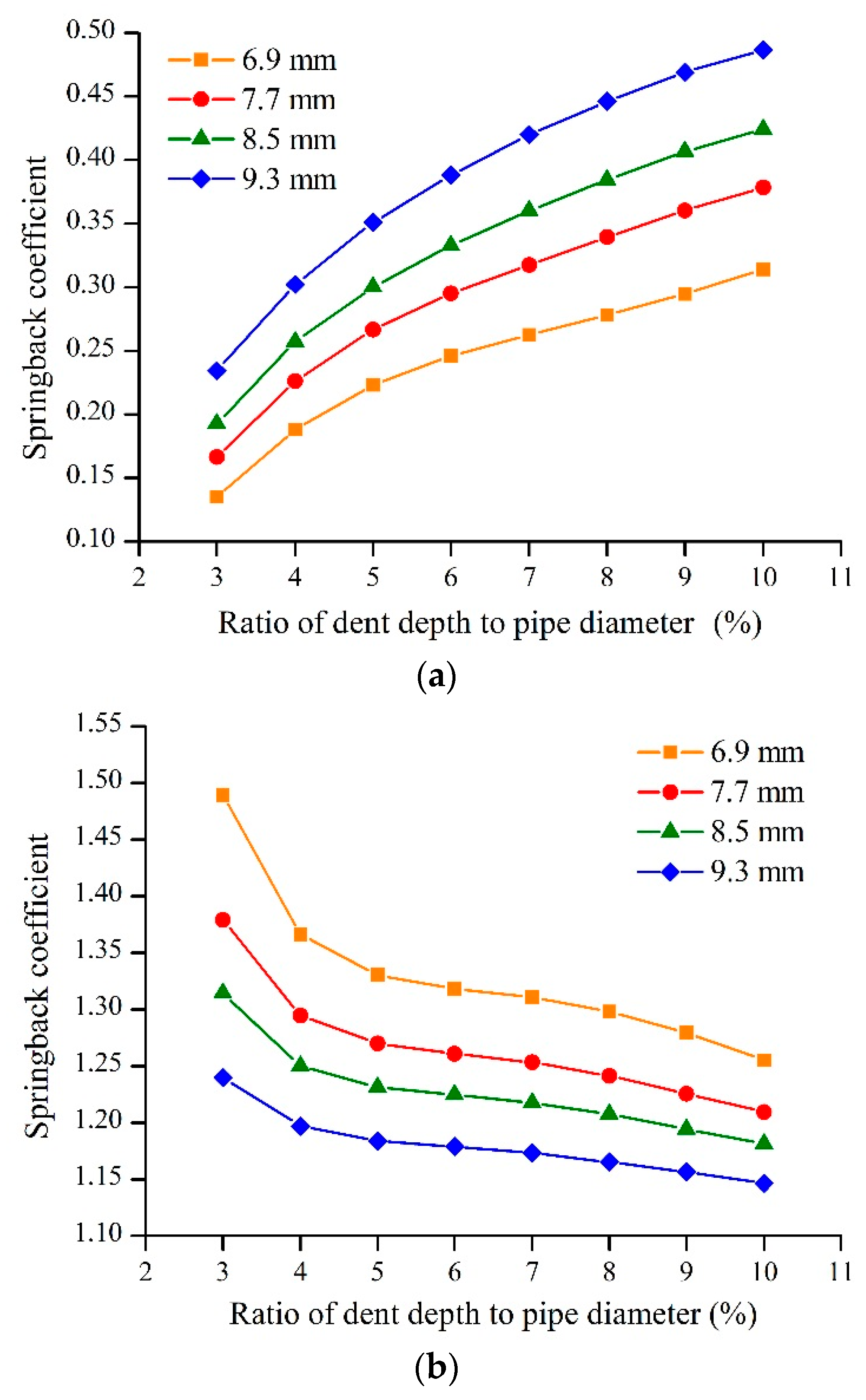
The indenter with an a/b of 0.3 was used to create a dent on the pipe with internal pressure of 6 MPa in the 0° position. Figure 6 shows the relationships between the dent depth and springback coefficient and the pipe wall thickness. According to Figure 6a, the springback coefficient increased with increasing pipe wall thickness. Thus, a thicker wall thickness led to larger springback coefficient, which is the same as the conclusion in literature [16]. The springback coefficient increased with increasing dent depth for a fixed wall thickness because the stress concentration in the dent influenced the springback. A greater dent depth created a larger stress concentration, making springback more difficult as described in literature [14,17]. The slope of the springback coefficient vs. the dent depth slightly increased with decreasing dent depth.
According to Figure 6b, the springback coefficient decreased with increasing dent depth and had values between 1.15 and 1.5. A larger wall thickness produced a smaller range of springback coefficients that decreased more gradually. The springback coefficient decreased with increasing pipe wall thickness for a fixed dent depth.
4.2. Internal Pressure
The indenter with an a/b of 0.3 was used to create dents on the pipe with wall thickness of 6.9 mm at the 0° position. Figure 7 displays the dent depths vs. springback coefficients for various internal pressures. According to Figure 7a, the springback coefficient decreased with increasing internal pressure because the hoop stress due to the internal pressure continuously applies an outward force to the dent. The slope of the springback coefficient vs. the dent depth decreased with increasing dent depth and internal pressure. This relationship was especially pronounced for the dented pipe with a pressure of 8 MPa. For the dented pipe with a pressure of 8 MPa, the slope of the springback coefficient vs. the dent depth was nearly constant with increasing dent depth.
According to Figure 7b, the springback coefficient decreased with decreasing internal pressure and increasing dent depth. For dented pipes with pressures of 6 and 8 MPa, the slope of the springback coefficient vs. the dent depth decreased with increasing dent depth. For the dented pipes with pressures of 2 and 4 MPa, the slope of the springback coefficient vs. the dent depth was nearly constant with increasing dent depth. Thus, the internal pressure significantly influenced the springback coefficient.
4.3. Indenter Size
The indenter was used to create dents on the pipe with a wall thickness of 9.3 mm and internal pressure of 6 MPa at the 0° position. Figure 8 shows the springback coefficients of the dented pipe with variations in the indenter size and dent depth. According to Figure 8a, the springback coefficient increased with increasing indenter size because a smaller indenter size resulted in a smaller plastic deformation area of the pipe for a fixed dent depth. This was more prominent for the indenter with an a/b of 0.1.
According to Figure 8b, the springback coefficient decreased with increasing indenter size. The springback coefficients were between 1.1 and 1.2 for the indenters with a/b values of 0.3, 0.5, and 0.7, while they were between 1.25 and 1.35 for the indenter with an a/b of 0.1. Thus, the internal pressure has a greater effect on the dent springback as the indenter size decreased.
4.4. Dent Location
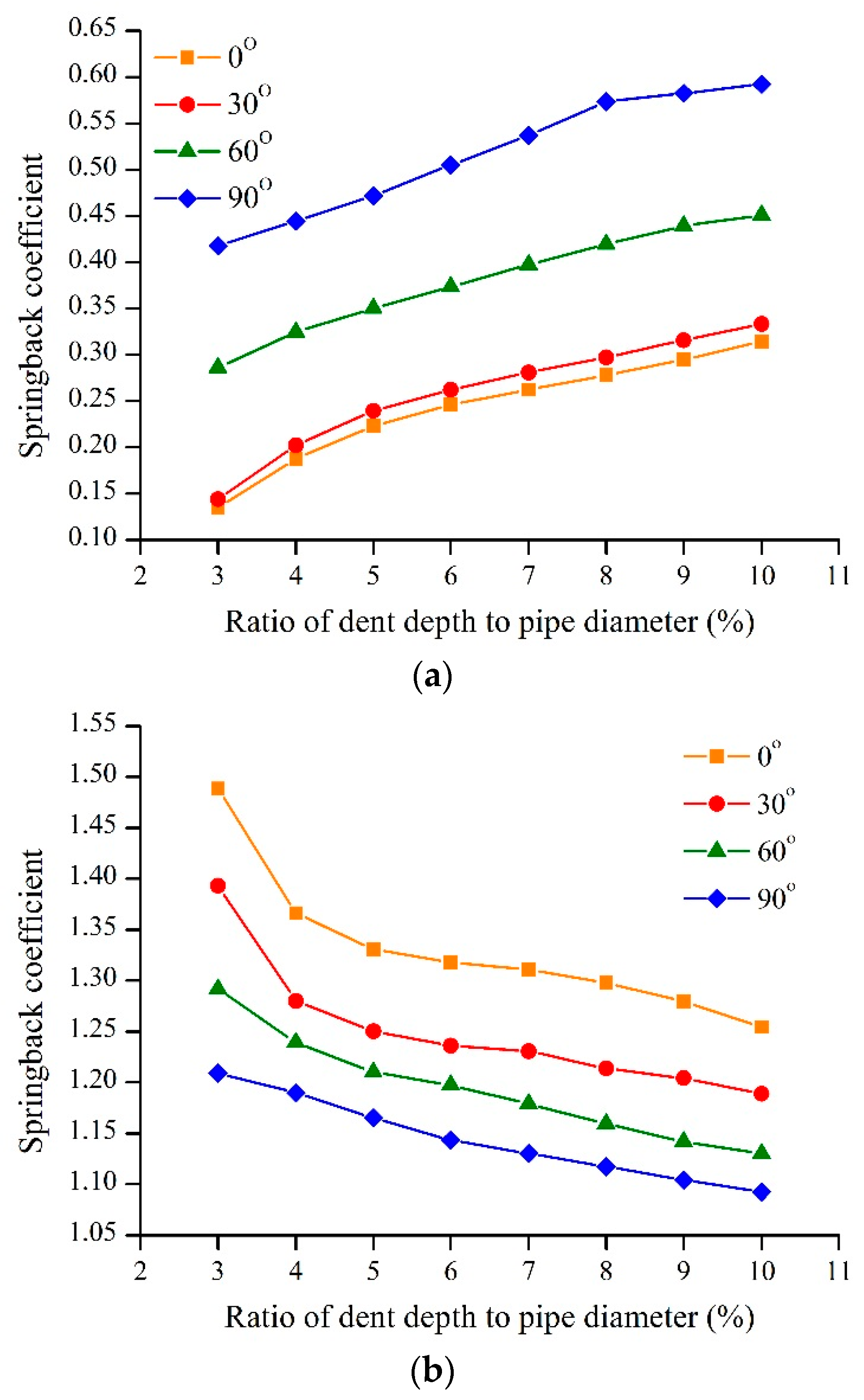
The indenter with an a/b of 0.3 was used to manufacture dents on the pipe with wall thickness of 6.9 mm and internal pressure of 6 MPa. Figure 9 shows the relationship between the dent depth and springback coefficient to variations of the dent location. According to Figure 9a, there were almost no changes in the springback coefficients for dents located at 0° and 30°. However, the springback coefficient increased as the dent location angle increased. The effect was more prominent for the dents located at 60° and 90°. This is partly due to the influence of the boundary conditions. According to the definition of constrained and unconstrained dents, the range of 120° at the bottom of the pipe is constrained by the vertical displacement. As the dented area moves closer to the bottom of the pipe, the constrained area of the pipe is larger, which restrains the springback of the dent, resulting in an increase in the springback coefficient.
According to Figure 9b, the springback coefficient decreased with increasing dent location and depth, and the springback coefficients were between 1.1 and 1.5. The curve of the springback coefficient vs. the dent depth was slightly smoother with increasing dent depth.
5. Significance Analysis of Influential Factors
5.1. Orthogonal Design
Based on the numerical simulation results, the orthogonal experimental design method and the Grey relational degree were combined to analyze the significance of the factors, such as the wall thickness, internal pressure, indenter size, dent location, and dent depth, on the springback coefficient [28]. Taking the springback coefficient after pressurization as an example, an orthogonal scheme with 5 factors and 4 levels was designed. The levels of each influential factor are summarized in Table 2. The springback coefficient was taken as the evaluation criterion for the corresponding simulations. The orthogonal test design of L16 (45) used to design the orthogonal test table is shown in Table 3.
5.2. Grey Correlation Degree Calculation
The influential factors were taken as a comparison sequence. Let the comparison sequence be . The number of trials at different times was denoted as t. Therefore, the matrix of s comparison sequences was [29]:
The springback coefficient was taken as the reference sequence. Let the reference sequence be . Therefore, the matrix of m comparison sequences was:
where yjk and xik are of the same order of magnitude.
The correlation degree was regarded as the shape similarity between the reference and comparison sequence curves. Therefore, the differences between the curves were used as a measure of the correlation degree.
The absolute value of the difference between the corresponding elements of the comparison and reference sequences was:
Therefore, the correlation degree between the i-th comparison sequence and the j-th reference sequence at t time was:
where ρ is the resolution coefficient, which was introduced to improve the significance of the difference between the correlation coefficients.
The acquisition process of the comparison and reference sequences was subject to disturbances due to uncertainties, which can create outliers in the data because the system is inevitably affected by various uncertainties in the operation process. To avoid the disturbances of outliers caused by uncertain factors and to make the correlation coefficient better reflect objective reality, the value of ρ was determined according to the following methods.
which is the mean value of the absolute value of the differences between all comparison sequences and the j-th reference sequence, calculated as follows
when takes and when takes .
The resolution coefficient ρ was calculated as
The correlation degree is a measure of the correlation between the reference and comparison sequences. It describes the relative changes of the two sequences. If the relative changes are mostly consistent during the whole development process, the correlation degree between them is large; otherwise, the correlation degree is small. The correlation coefficient is a measure at a fixed time. Therefore, the average value of the correlation number at each time, which was taken as a measure of the degree of correlation in the comparison of the whole process, was:
where is the Grey relation of xi to yj abbreviated as rij.
5.3. Significance Analysis
The Grey correlation degree between the factors and springback coefficients was obtained using Equation (10) after normalizing the data in Table 3: r = (0.603, 0.641, 0.593, 0.688, 0.653). The value of ρ was 0.4. The factors were sorted according to the degree of correlation. The dent location had the greatest influence, followed by the dent depth and internal pressure, and finally the wall thickness. The indenter size had less influence on the springback coefficient.
Similarly, the Grey correlation degree between the factors and the springback coefficients after de-pressurization was calculated: r = (0.642, 0.835, 0.631, 0.598, 0.652). The value of ρ was 0.7. The internal pressure had the greatest correlation with the springback coefficient, reaching a value of 0.835, which indicates that the internal pressure had the closest relationship with the springback coefficient. The factors most closely related to the springback coefficient were the dent depth and wall thickness. The influential factor was again the indenter size. The lowest correlation parameter was the dent location.
6. Nonlinear Regression Analysis
6.1. Formula of Springback Coefficient after Pressurization
Based on the FE results and the main factors affecting the springback, a formula for calculating the springback coefficient of the dented pipeline after pressurization was fit, which provided a relevant basis for pipeline risk assessment. The dependence of the springback coefficient of the dented pipeline on the wall thickness, internal pressure, indenter size, dent location, and dent depth was expressed by a power function. The relationship between the springback coefficient and the influential factors was assumed to be [30]:
where Hp is the springback coefficient of the dented pipeline after pressurization, d is the dent depth before pressurization, dp is the dent depth after pressurization, D is the outer diameter of the pipe, t is the wall thickness of the pipe, E is Young’s modulus for X60 pipe, P is the internal pressure of the pipe, a is the short axis of the ellipsoidal indenter, b is the long axis of the indenter, β is the dent location and α, δ, γ, ς, τ, υ are the undetermined coefficients.
The undetermined coefficients of Equation (11) were fit using a nonlinear regression method. Therefore, the formula for calculating the springback coefficient of the dented pipeline after pressurization was as follows:
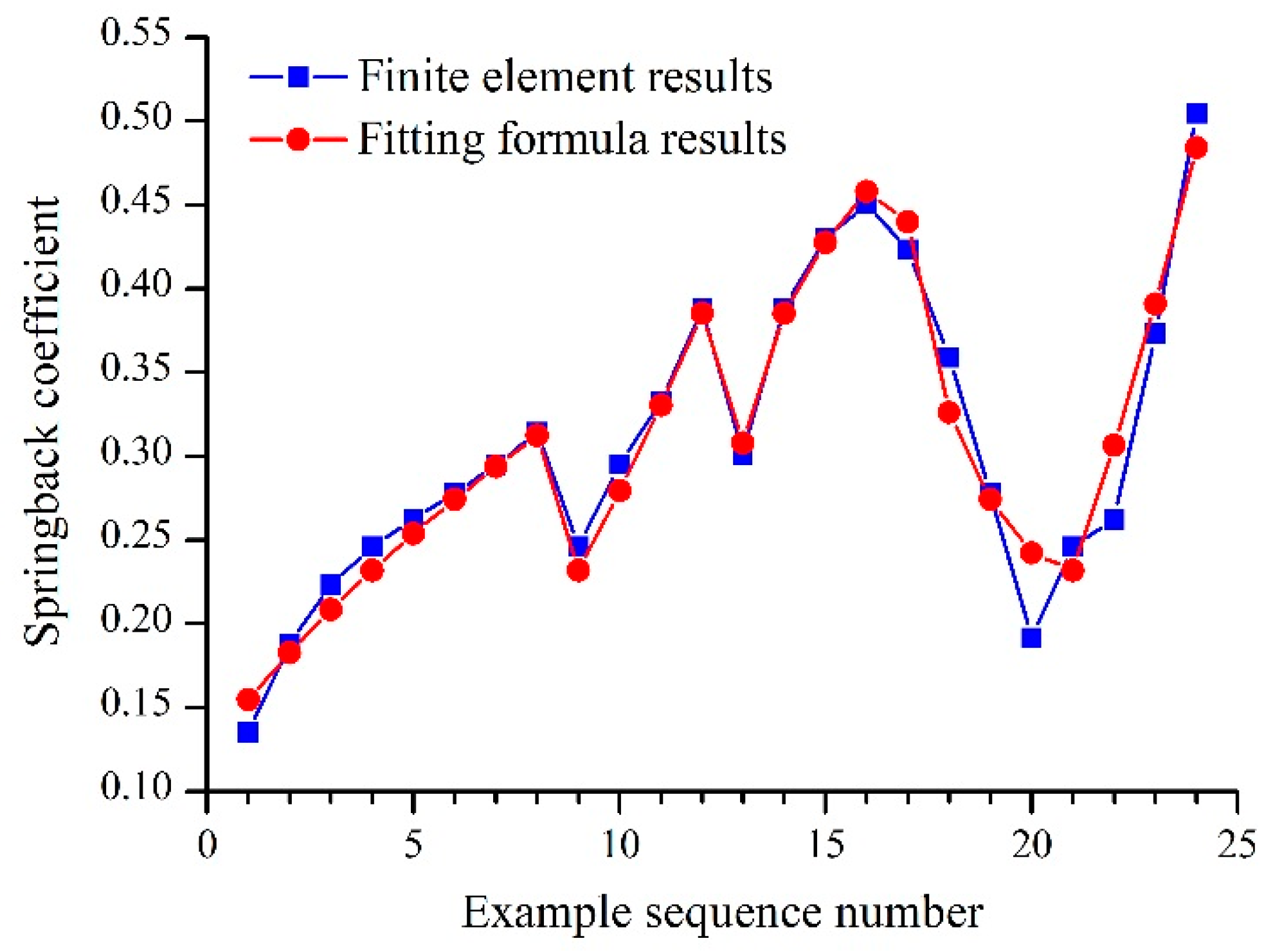
Figure 10 shows the comparison of the fitting formula results with the FE results. The squared sum of the correlation coefficients of the formula, R2, was 0.956, indicating a good fit.
6.2. Formula of Springback Coefficient after De-Pressurization
Based on the FE results, the formula for calculating the springback coefficient of the dented pipeline after de-pressurization was fit. The dependence of the springback coefficient of the dented pipeline on the wall thickness, internal pressure, indenter size, dent location, and dent depth was expressed by a power function. The relationship between the springback coefficient and the influencing factors was assumed to be
where Hr is the springback coefficient of the dented pipeline after de-pressurization, dr is the dent depth after de-pressurization, dp is the dent depth before de-pressurization, D is the outer diameter of the pipe, t is the wall thickness of the pipe, E is Young’s modulus for X60 pipe, P is the internal pressure of the pipe, a is the short axis of the ellipsoidal indenter, b is the long axis of the indenter, β is the dent location, d is the dent depth before pressurization and α, δ, γ, ς, τ, υ are the undetermined coefficients.
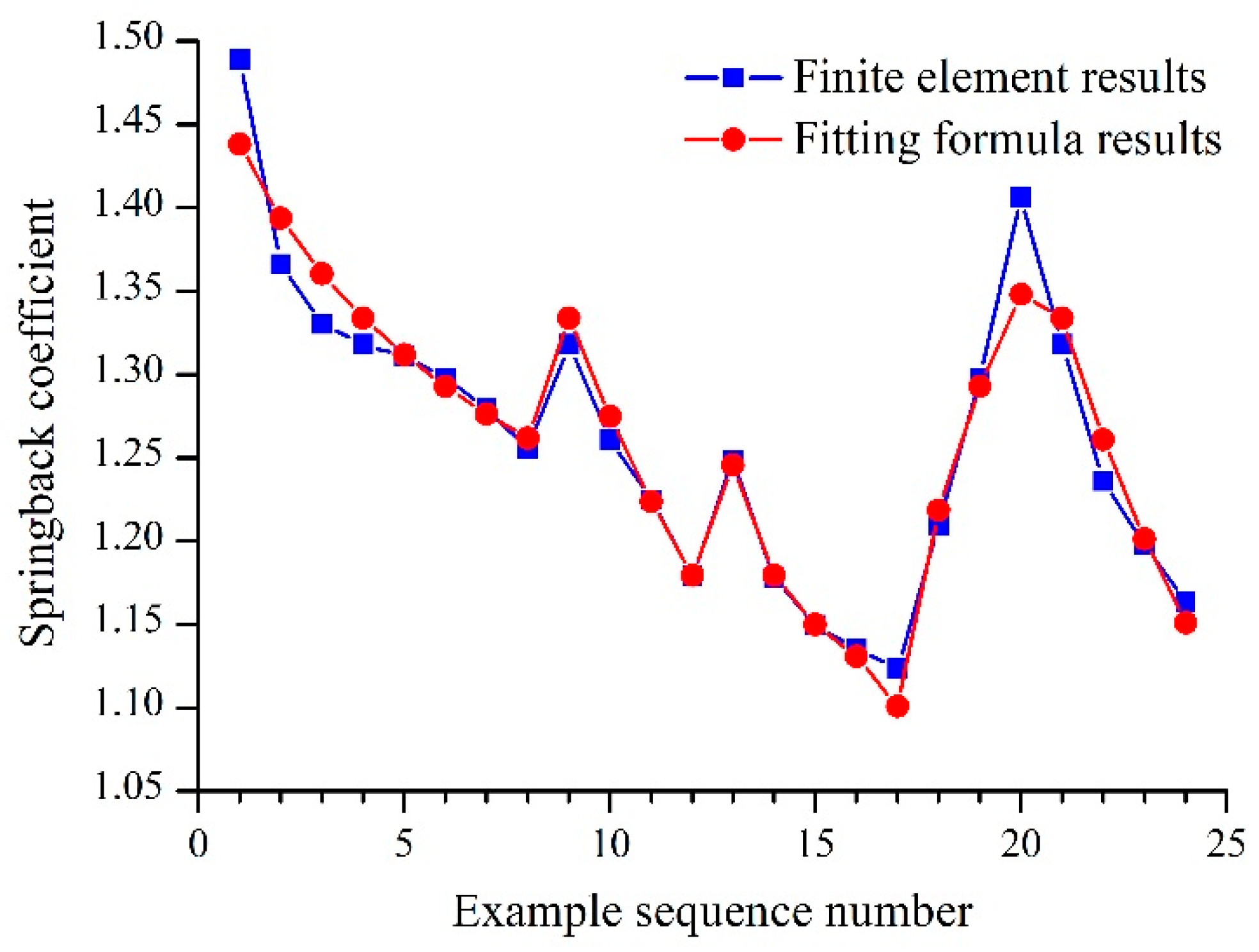
The undetermined coefficients of Equation (13) were fit using a nonlinear regression method. Therefore, the formula for calculating the springback coefficient of the dented pipeline after de-pressurization was as follows:
Figure 11 shows the comparison of the fitting formula results with the FE results. The squared sum of the correlation coefficients of the formula was 9.45 and the fitting effect was good. The above formulas can be used to calculate the springback coefficient of an X60 pipe that corresponds to the pipe parameters used in this study.
7. Conclusions
- (1)
- To quickly and accurately establish an FE model of a dented pipe and to automate the simulation and analysis, ABAQUS secondary development technology was introduced. The plug-in interface for the parametric modeling and analysis of a dented pipe was programmed using RSG of ABAQUS, whose corresponding kernel script was compiled to cascade with it. This method avoids repeated modeling, saves time and energy, and effectively improves the automation of the simulation analysis process.
- (2)
- After pressurization, a thicker wall thickness led to larger springback coefficient. A larger internal pressure led to greater springback. The springback coefficient increased with increasing indenter size and dent depth. The closer the dent was to the bottom of the pipeline, the smaller the springback coefficient. Therefore, a dent at the top of the pipe should be of most concern in the evaluation of a dent, where the dent springs back most fully.
- (3)
- After de-pressurization, the springback coefficient decreased with increasing dent depth, wall thickness, indenter size, and dent location. However, the springback coefficient increased with increasing internal pressure. The springback coefficients were concentrated between 1.1 and 1.5. Therefore, the literature [9,11] values of the springback coefficient without internal pressure of 1.43 are not very accurate.
- (4)
- The effects of the influential factors on the springback coefficient were obtained by a combination of an orthogonal experimental design and the Grey correlation. For the springback coefficient after pressurization, the order of importance of the influential factors from largest to smallest was the dent location, dent depth, internal pressure, wall thickness, and indenter size. For the springback coefficient after de-pressurization, the order of importance of the influential factors from largest to smallest was the internal pressure, dent depth, wall thickness, indenter size, and dent location.
- (5)
- Quantitative expressions of the springback coefficient and influence factors were fit using a nonlinear regression method, which provides a reference for the calculation of springback of dented pipes.
Author Contributions
P.Z. conceived and designed the analysis. Y.H. established the numerical model, performed the factors analysis and wrote the paper. Y.W. gave suggestions.
Funding
This research work was supported by National Natural Science Foundation of China (50974105), Major Consultation and Research Project of China Academy of Engineering (2011-ZD-20) and Specialized Research Fund for Doctoral Programs in Colleges and Universities (20105121110003).
Acknowledgments
We thank LetPub (www. LetPub.com) for its linguistic assistance during the preparation of this manuscript.
Conflicts of Interest
The authors declare no conflict of interest.
Nomenclature
| D | outside diameter of pipe (mm) |
| t | wall thickness of pipe (mm) |
| P | internal pressure of pipe (MPa) |
| a | short axis of ellipsoidal indenter (mm) |
| b | long axis of the ellipsoidal indenter (mm) |
| β | dent location (°) |
| d | dent depth before pressurizing (mm) |
| dp | dent depth after pressurizing (mm) |
| dr | dent depth after releasing pressure (mm) |
| Hp | springback coefficient after pressurizing |
| Hr | springback coefficient after releasing pressure |
| E | Young’s modulus (MPa) |
| α | undetermined coefficient |
| δ | undetermined coefficient |
| γ | undetermined coefficient |
| ς | undetermined coefficient |
| τ | undetermined coefficient |
| υ | undetermined coefficient |
References
- Toyoshima, Y.; Hamori, S. Measuring the Time-Frequency Dynamics of Return and Volatility Connectedness in Global Crude Oil Markets. Energies 2018, 11, 2893. [Google Scholar] [CrossRef]
- Chala, G.T.; Abd Aziz, A.R.; Hagos, F.Y. Natural Gas Engine Technologies: Challenges and Energy Sustainability Issue. Energies 2018, 11, 2934. [Google Scholar] [CrossRef]
- Allouti, M.; Schmitt, C.; Pluvinage, G.; Gilgert, J.; Hariri, S. Study of the influence of dent depth on the critical pressure of pipeline. Eng. Fail. Anal. 2012, 21, 40–51. [Google Scholar] [CrossRef]
- Ghazijahani, T.G.; Jiao, H.; Holloway, D. Plastic buckling of dented steel circular tubes under axial compression: An experimental study. Thin Walled Struct. 2015, 92, 48–54. [Google Scholar] [CrossRef]
- Dawson, S.J. Emerging techniques for enhanced assessment and analysis of dents. In Proceedings of the IPC 2006 6th International Pipeline Conference, Calgary, AB, Canada, 25–29 September 2006. [Google Scholar]
- Alashti, R.A.; Jafari, S.; Hosseinipour, S.J. Experimental and numerical investigation of ductile damage effect on load bearing capacity of a dented API XB pipe subjected to internal pressure. Eng. Fail. Anal. 2015, 47, 208–228. [Google Scholar] [CrossRef]
- Adib, H.; Jallouf, S.; Schmitt, C.; Carmasol, A.; Pluvinage, G. Evaluation of the effect of corrosion defects on the structural integrity of X52 gas pipelines using the SINTAP procedure and notch theory. Int. J. Press. Vessel. Pip. 2007, 84, 123–131. [Google Scholar] [CrossRef]
- ASME B31.8-2014. Gas Transmission and Distribution Piping Systems; American Society of Mechanical Engineers: New York, NY, USA, 2014. [Google Scholar]
- API 1156-1997. Effects of Smooth and Rock Dents on Liquid Petroleum Pipelines; American Petroleum Institute: Washington, DC, USA, 1997. [Google Scholar]
- Maxey, W.A. Outside Force Defect Behavior. In Proceedings of the 7th Symposium on Line Pipe Research, Houston, TX, USA, 14–16 October 1986. [Google Scholar]
- Corder, I.; Corbin, P. EPRG recommendations for the assessment of the resistance of pipelines to external damage. In Proceedings of the EPRG/PRC 10th Biennial Joint Technical Meeting on Line Pipe Research, Cambridge, UK, 18–21 April 1995. [Google Scholar]
- Cosham, A.; Hopkins, P. The effect of dents in pipelines-guidance in the pipeline defect assessment manual. Int. J. Press. Vessel. Pip. 2004, 81, 127–139. [Google Scholar] [CrossRef]
- Sha, S.Y.; Yan, B.C.; Jia, G.M.; Zhao, L.Y.; Tian, S.J.; Liu, Y.Q.; Yu, Z.B. Full-scale dent rebound test of X65 steel oil pipeline. Oil Gas Storage Transp. 2016, 35, 475–477. [Google Scholar]
- Yang, Q.; Shuai, J.; Zuo, S.Z. Research status of dented pipeline. Oil Gas Storage Transp. 2009, 28, 10–15. [Google Scholar]
- Hanif, W.; Kenny, S. Mechanical damage and fatigue assessment of dented pipelines using FEA. In Proceedings of the IPC 2014 10th International Pipeline Conference, Calgary, AB, Canada, 29 September–3 October 2014. [Google Scholar]
- Bastard, A.L. Influence of internal pressure for depth measurement on a dent. In Proceedings of the IPC 2006 6th International Pipeline Conference, Calgary, AB, Canada, 25–29 September 2006. [Google Scholar]
- Baek, J.H.; Kim, Y.P.; Kim, W.S.; Koo, J.M.; Seok, C.S. Load bearing capacity of API X65 pipe with dent defect under internal pressure and in-plane bending. Mater. Sci. Eng. A 2012, 540, 70–82. [Google Scholar] [CrossRef]
- Hyde, T.H.; Luo, R.; Becker, A.A. Prediction of three-dimensional residual stresses at localised indentations in pipes. Int. J. Press. Vessel. Pip. 2012, 93–94, 1–11. [Google Scholar] [CrossRef]
- Xiong, W.; Gan, Z.; Xiong, S.P.; Yuan, S.; Li, G.J. Secondary development for ABAQUS based on MATLAB, part 1: Solution and key technologies. J. Plast. Eng. 2012, 19, 21–26. [Google Scholar]
- Kormi, K.; Webb, D.C.; Johnson, W. The application of the FEM to determine the response of a pretorsioned pipe cluster to static or dynamic axial impact loading. Comput. Struct. 1997, 62, 353–368. [Google Scholar] [CrossRef]
- Zeinoddini, M.; Ezzati, M.; Fakheri, J. Uniaxial strain ratcheting behavior of dented steel tubular: An experimental study. Eng. Fail. Anal. 2014, 44, 202–216. [Google Scholar] [CrossRef]
- Azadeh, M.; Taheri, F. On the response of dented stainless-steel pipes subject to cyclic bending moments and its prediction. Thin Walled Struct. 2016, 99, 12–20. [Google Scholar] [CrossRef]
- Zeinoddini, M.; Ezzati, M.; Parke, G.A.R. Plastic buckling, wrinkling and collapse behaviour of dented X80 steel line pipes under axial compression. J. Loss Prev. Process Ind. 2015, 38, 67–78. [Google Scholar] [CrossRef]
- Baek, J.H.; Kim, Y.P.; Kim, C.M.; Kim, W.S.; Seok, C.S. Effects of pre-strain on the mechanical properties of API 5L X65 pipe. Mater. Sci. Eng. A 2010, 527, 1473–1479. [Google Scholar] [CrossRef]
- Hyde, T.H.; Luo, R.; Becker, A.A. Predictions of three-dimensional stress variations in indented pipes due to internal pressure fluctuations. J. Strain Anal. Eng. Des. 2011, 46, 510–522. [Google Scholar] [CrossRef]
- Li, C.B.; Dang, S.H. Plastic damage analysis of oil and gas pipelines with unconstrained and constrained dents. Eng. Fail. Anal. 2017, 77, 39–49. [Google Scholar] [CrossRef]
- Iflefel, I.B.; Moffat, D.G.; Mistry, J. The interaction of pressure and bending on a dented pipe. Int. J. Press. Vessel. Pip. 2005, 82, 761–769. [Google Scholar] [CrossRef]
- Seberry, J.; Finlayson, K.; Adams, S.S.; Wysocki, T.T. The Theory of quaternion orthogonal designs. IEEE Trans. Signal Process. 2008, 56, 256–265. [Google Scholar] [CrossRef]
- Chen, Y.M.; Zhang, M. Cubic spline based grey absolute relational grade model. Syst. Eng. Theory Pract. 2015, 35, 1304–1310. [Google Scholar]
- Lv, Y.F.; Ma, T.X.; Zou, H.X.; Liu, W.Y. Study on springback coefficient of long distance dented pipeline based on FEM. Forg. Stamp. Technol. 2017, 42, 194–200. [Google Scholar]
Figure 1.
True stress versus true strain for API X60 pipe.
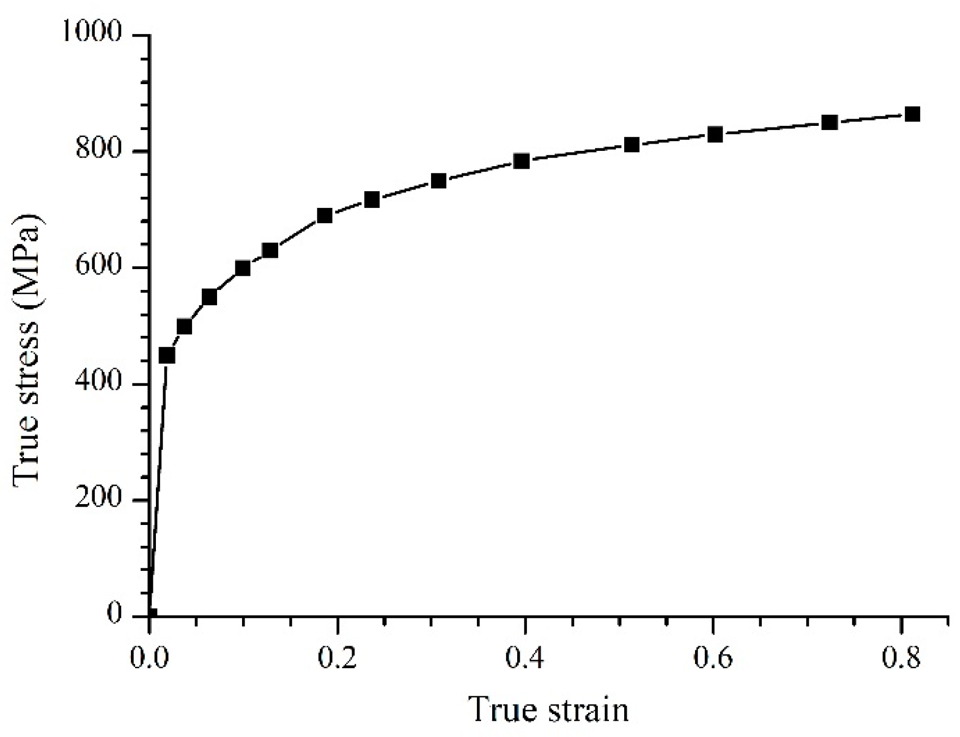
Figure 2.
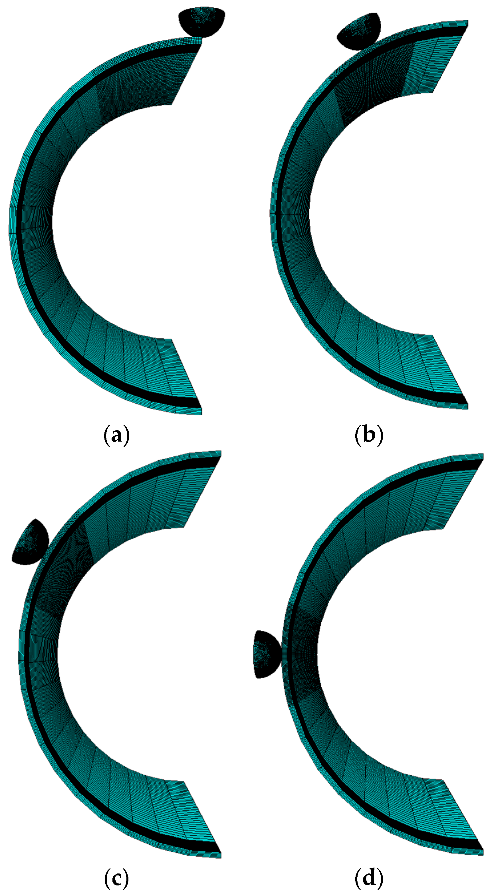
Illustration of the four locations: (a) 0°; (b) 30°; (c) 60°; (d) 90°.

Figure 3.
Denting process for the pipe.

Figure 4.
Dent springback test device.

Figure 5.
Comparison of test results [13] with finite element results.
Figure 5.
Comparison of test results [13] with finite element results.
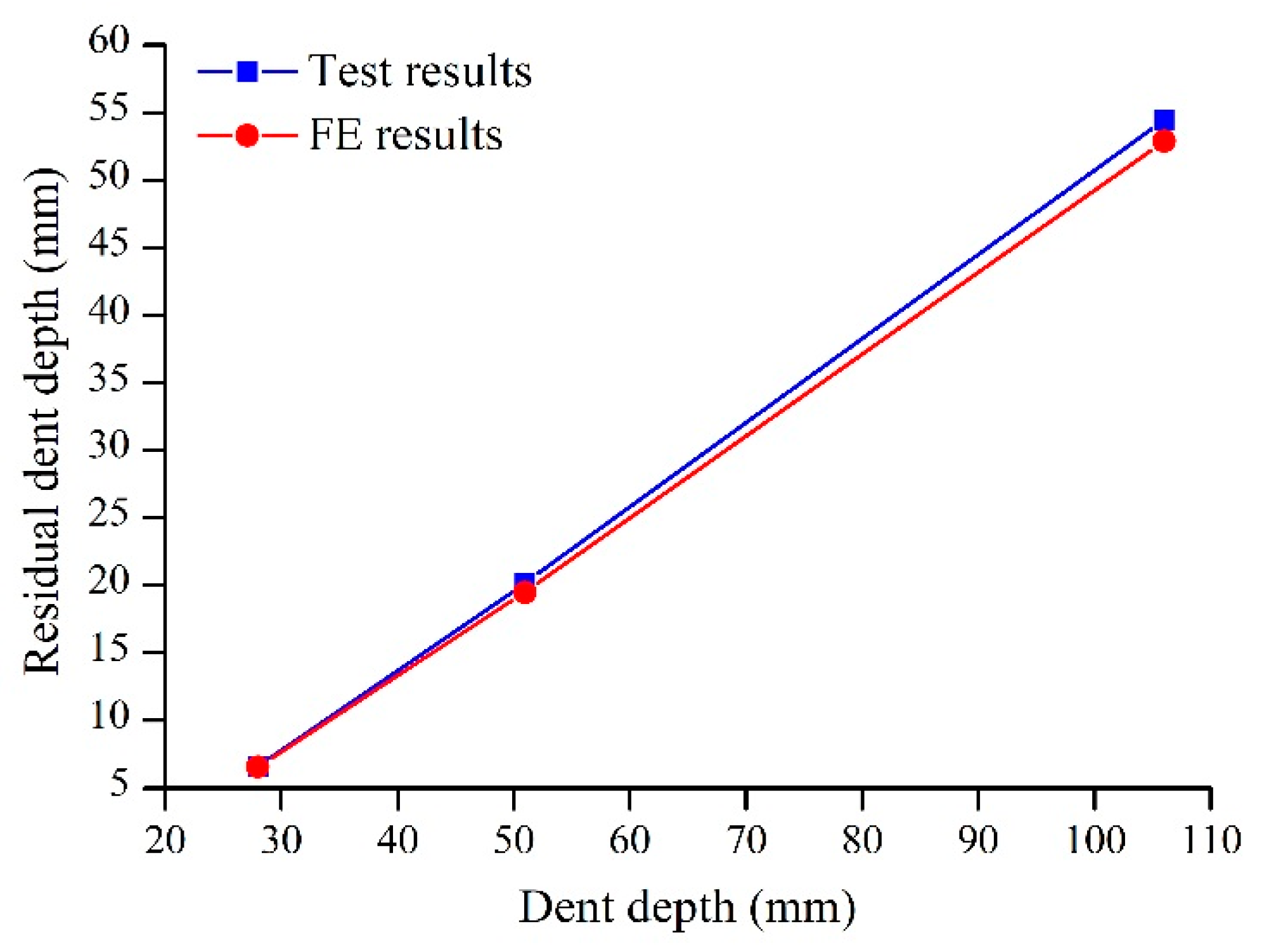
Figure 6.
Dent depth and springback coefficient with variation of the wall thicknesses during denting: (a) pressurization; (b) de-pressurization.
Figure 6.
Dent depth and springback coefficient with variation of the wall thicknesses during denting: (a) pressurization; (b) de-pressurization.

Figure 7.
Dent depth and springback coefficient with variation of the internal pressures during denting: (a) pressurization; (b) de-pressurization.
Figure 7.
Dent depth and springback coefficient with variation of the internal pressures during denting: (a) pressurization; (b) de-pressurization.
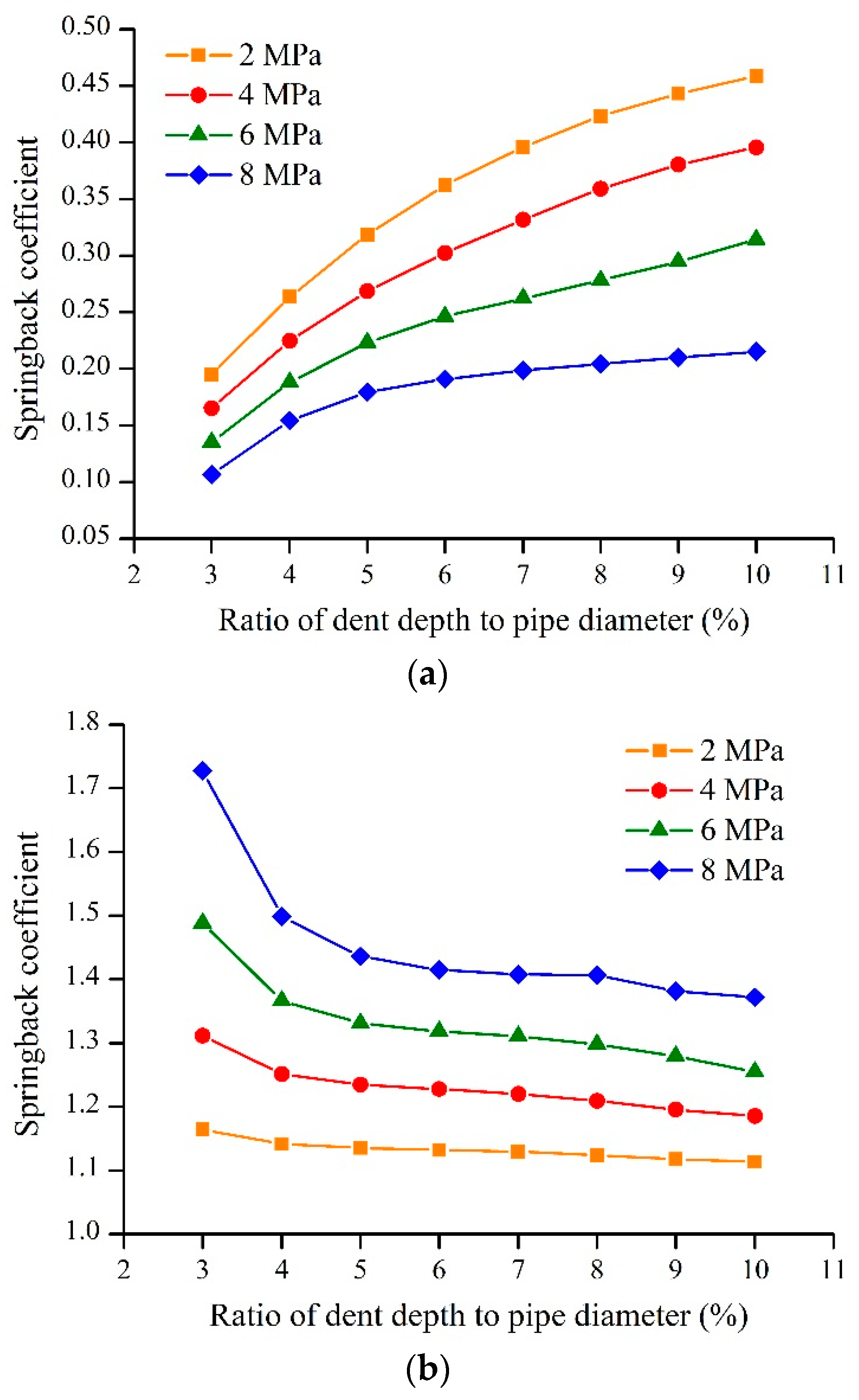
Figure 8.
Dent depth and springback coefficient with variation of the indenter sizes during denting: (a) pressurization; (b) de-pressurization.
Figure 8.
Dent depth and springback coefficient with variation of the indenter sizes during denting: (a) pressurization; (b) de-pressurization.
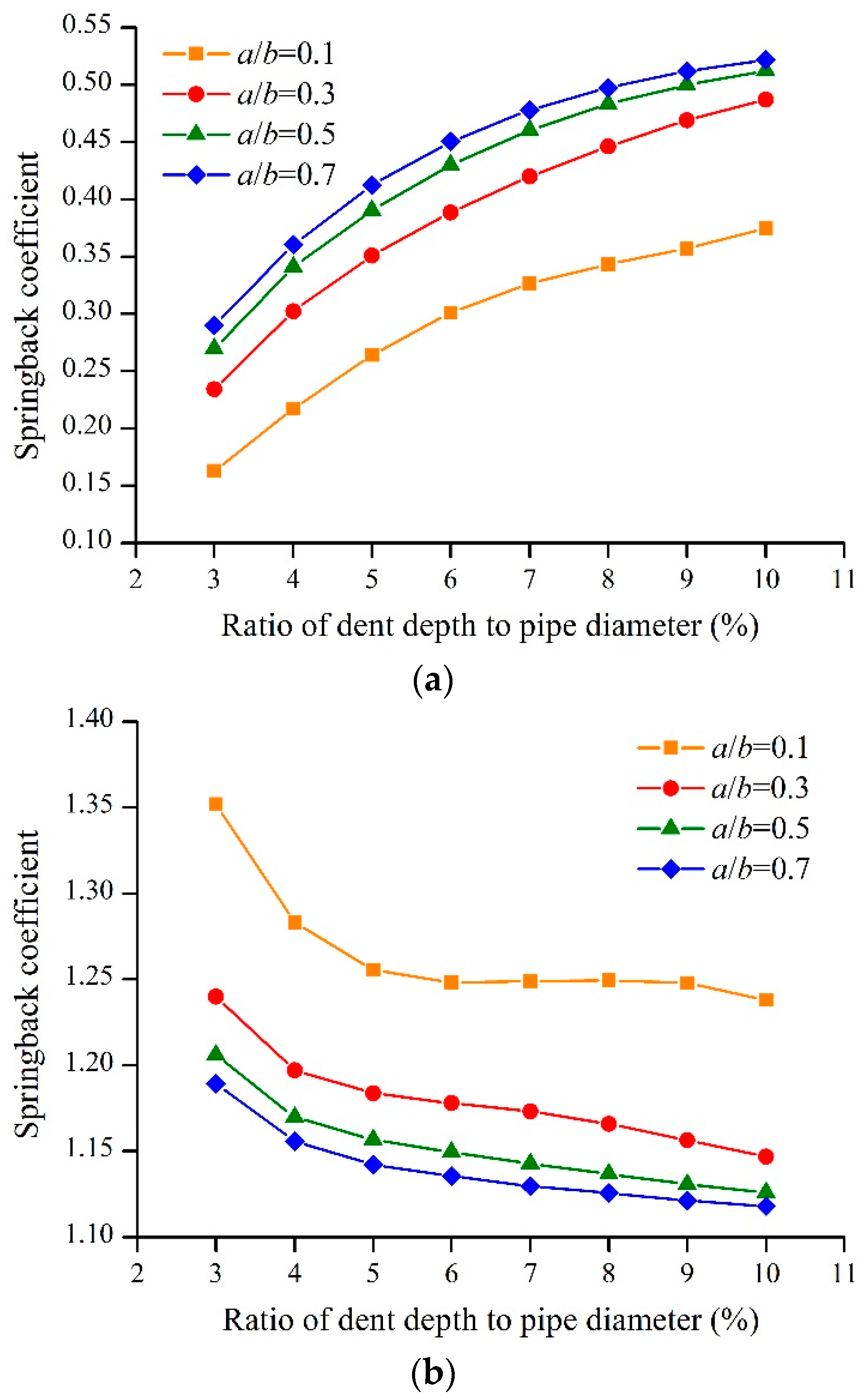
Figure 9.
Dent depth and springback coefficient with variation of the dent locations during denting: (a) pressurization; (b) de-pressurization.
Figure 9.
Dent depth and springback coefficient with variation of the dent locations during denting: (a) pressurization; (b) de-pressurization.

Figure 10.
Comparison of fitting formula results with FE results.

Figure 11.
Comparison of fitting formula results with FE results.


Table 1.
Material properties for API X60 pipe.
| Yield Stress | True Ultimate Tensile Stress | Young’s Modulus | Poisson’s Ratio |
|---|---|---|---|
| 451 MPa | 660 MPa | 2 × 10⁵ MPa | 0.3 |
Table 2.
Level setting of influencing factors.
| Factors | 1 | 2 | 3 | 4 | 5 | |
|---|---|---|---|---|---|---|
| Levels | Wall Thickness (mm) | Internal Pressure (MPa) | Indenter Size a/b | Dent Location (°) | Ratio of Dent Depth to Pipe Diameter | |
| 1 | 6.9 | 2 | 0.1 | 0 | 0.04 | |
| 2 | 7.7 | 4 | 0.3 | 30 | 0.06 | |
| 3 | 8.5 | 6 | 0.5 | 60 | 0.08 | |
| 4 | 9.3 | 8 | 0.7 | 90 | 0.1 | |
Table 3.
Orthogonal test design tables for various influencing factors.
| Number | Influence Factors | Springback Coefficient | ||||
|---|---|---|---|---|---|---|
| Wall Thickness (mm) | Internal Pressure (MPa) | Indenter Size a/b | Dent Location (°) | Ratio of Dent Depth to Pipe Diameter | ||
| 1 | 6.9 | 2 | 0.1 | 0 | 0.04 | 0.185 |
| 2 | 6.9 | 4 | 0.3 | 30 | 0.06 | 0.315 |
| 3 | 6.9 | 6 | 0.5 | 60 | 0.08 | 0.457 |
| 4 | 6.9 | 8 | 0.7 | 90 | 0.1 | 0.475 |
| 5 | 7.7 | 2 | 0.3 | 60 | 0.1 | 0.620 |
| 6 | 7.7 | 4 | 0.1 | 90 | 0.08 | 0.648 |
| 7 | 7.7 | 6 | 0.7 | 0 | 0.06 | 0.368 |
| 8 | 7.7 | 8 | 0.5 | 30 | 0.04 | 0.258 |
| 9 | 8.5 | 2 | 0.5 | 90 | 0.06 | 0.725 |
| 10 | 8.5 | 4 | 0.7 | 60 | 0.04 | 0.508 |
| 11 | 8.5 | 6 | 0.1 | 30 | 0.1 | 0.368 |
| 12 | 8.5 | 8 | 0.3 | 0 | 0.08 | 0.328 |
| 13 | 9.3 | 2 | 0.7 | 30 | 0.08 | 0.568 |
| 14 | 9.3 | 4 | 0.5 | 0 | 0.1 | 0.553 |
| 15 | 9.3 | 6 | 0.3 | 90 | 0.04 | 0.567 |
| 16 | 9.3 | 8 | 0.1 | 60 | 0.06 | 0.358 |
© 2018 by the authors. Licensee MDPI, Basel, Switzerland. This article is an open access article distributed under the terms and conditions of the Creative Commons Attribution (CC BY) license (http://creativecommons.org/licenses/by/4.0/).
Share and Cite
MDPI and ACS Style
Zhang, P.; Huang, Y.; Wu, Y. Springback Coefficient Research of API X60 Pipe with Dent Defect. Energies 2018, 11, 3213. https://doi.org/10.3390/en11113213
AMA Style
Zhang P, Huang Y, Wu Y. Springback Coefficient Research of API X60 Pipe with Dent Defect. Energies. 2018; 11(11):3213. https://doi.org/10.3390/en11113213
Chicago/Turabian StyleZhang, Peng, Yunfei Huang, and Ying Wu. 2018. "Springback Coefficient Research of API X60 Pipe with Dent Defect" Energies 11, no. 11: 3213. https://doi.org/10.3390/en11113213
Note that from the first issue of 2016, this journal uses article numbers instead of page numbers. See further details here.