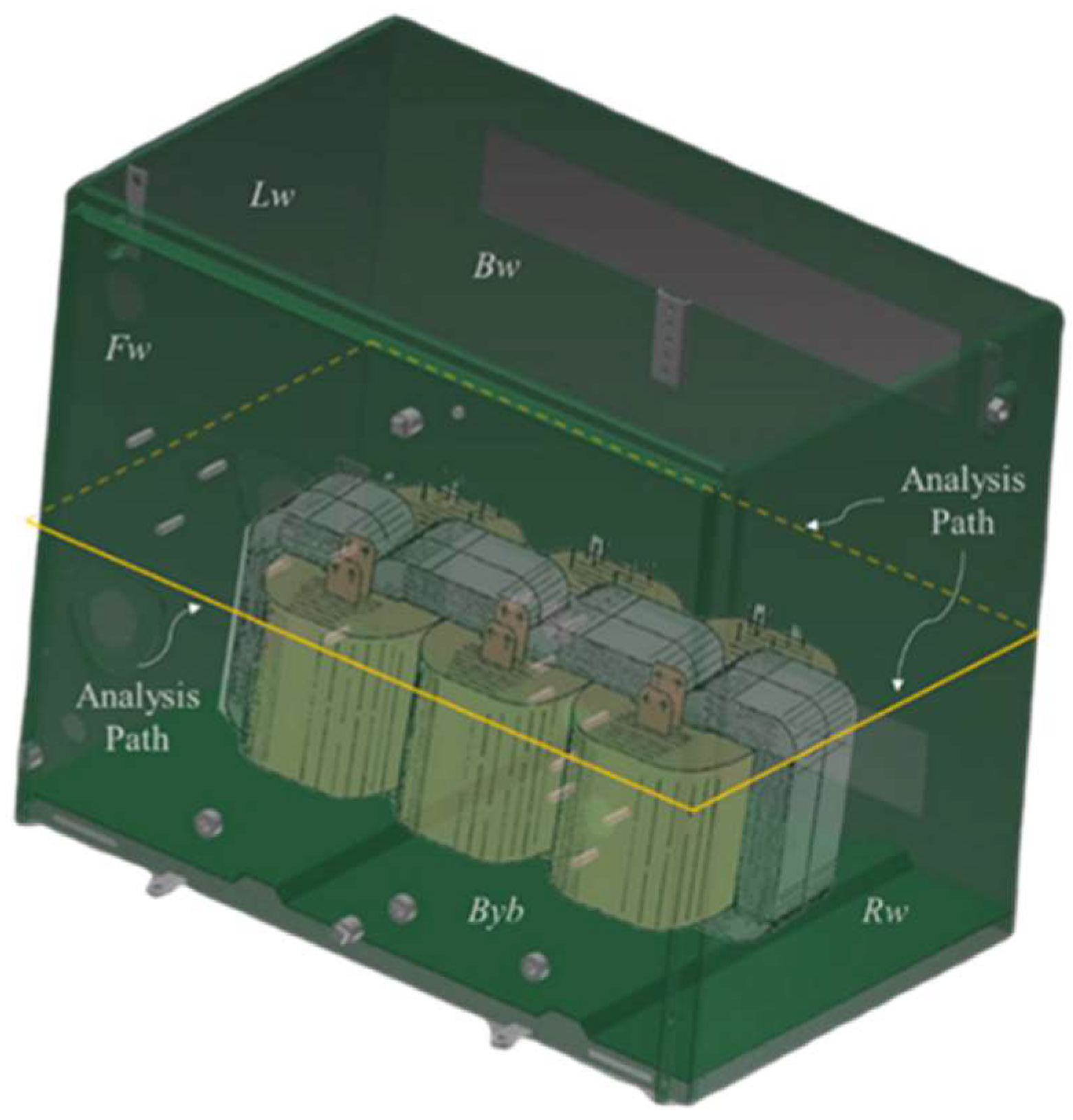
It is now widely recognised that some of the dispersion magnetic field generates stray losses within the structural components of the transformer and its associated tank. It is also recognised that as transformer power increases, this stray flux can cause substantial losses, resulting in heating effects. Recent advances in research focuses on various aspects of stray losses within transformer tanks. These studies employ a variety of methodologies, including numerical techniques such as the finite element method, as well as analytical and experimental approaches [
1,
2,
3,
4,
5,
6]. In this work, stray magnetic field refers to the dispersion magnetic field that reaches the tank and core clamp, and that produces stray losses in them. Research has demonstrated that stray losses resulting from induced current by eddy currents on tanks and other structural elements of distribution transformers can amount more than 15% of the corresponding load losses [
7]. In the transformer industry (especially in power transformers), this knowledge has led to adapting the transformer with magnetic shunts and other accessories to reduce load losses in their equipment. The challenge of identifying and mitigating parasitic losses in metallic components and transformer tanks is not a recent problem. It has been widely addressed in technical literature [
8,
9,
10,
11]. Some transformer manufacturers continue to use the empirical analytical formulas from this literature or from their experience in their current practices. Calculating stray losses requires an understanding of the stray magnetic field. To address this problem, efficient methods have emerged to quickly and approximately estimate the equivalent leakage reluctance, in particular by using the Reluctance Network Modelling (RNM) method [
12,
13]. The adoption of numerical methods, such as the Finite Element Method (FEM), has greatly facilitated the evaluation of the stray magnetic field and its associated additional losses. These methods make the simulation of stray magnetic fields in two- and three-dimensional scenarios more accessible and less complex. However, it is imperative to note that the utilisation of such methods comes at the expense of high computational requirements during the transformer design stage. These considerations are essential to effectively reduce stray losses and prevent hot spots. Furthermore, the application of the Finite Element Method (FEM) has allowed us to examine the impact of additional factors, such as geomagnetically induced currents, that contribute to increased stray losses in the transformer tank [
14]. Minimising stray losses in transformers represents an important competitive advantage in the industry. Consequently, there has been an increase in research dedicated to identifying the optimal location of magnetic shunts, with the objective of decreasing stray losses within the transformer tank [
15,
16]. The research is also focused on finding the optimal geometry of the magnetic shunt [
17]. The orientation of the shunt also plays an important role in reducing losses, which is why works such as [
18] clearly and conclusively confirm the effectiveness of orienting the shunt horizontally. In [
19] non-magnetic stainless steel, an insert was utilized to reduce the stray losses in a significant way in 80% of the region of the Tertiary Voltage Bushings of the transformer. The effect of magnetic shunts on shell-type transformers’ characteristics was recently analysed and determined. This helped in determining the magnetic flux density distributions, and the points with high values in the shell-type core and movable shunt sub-areas [
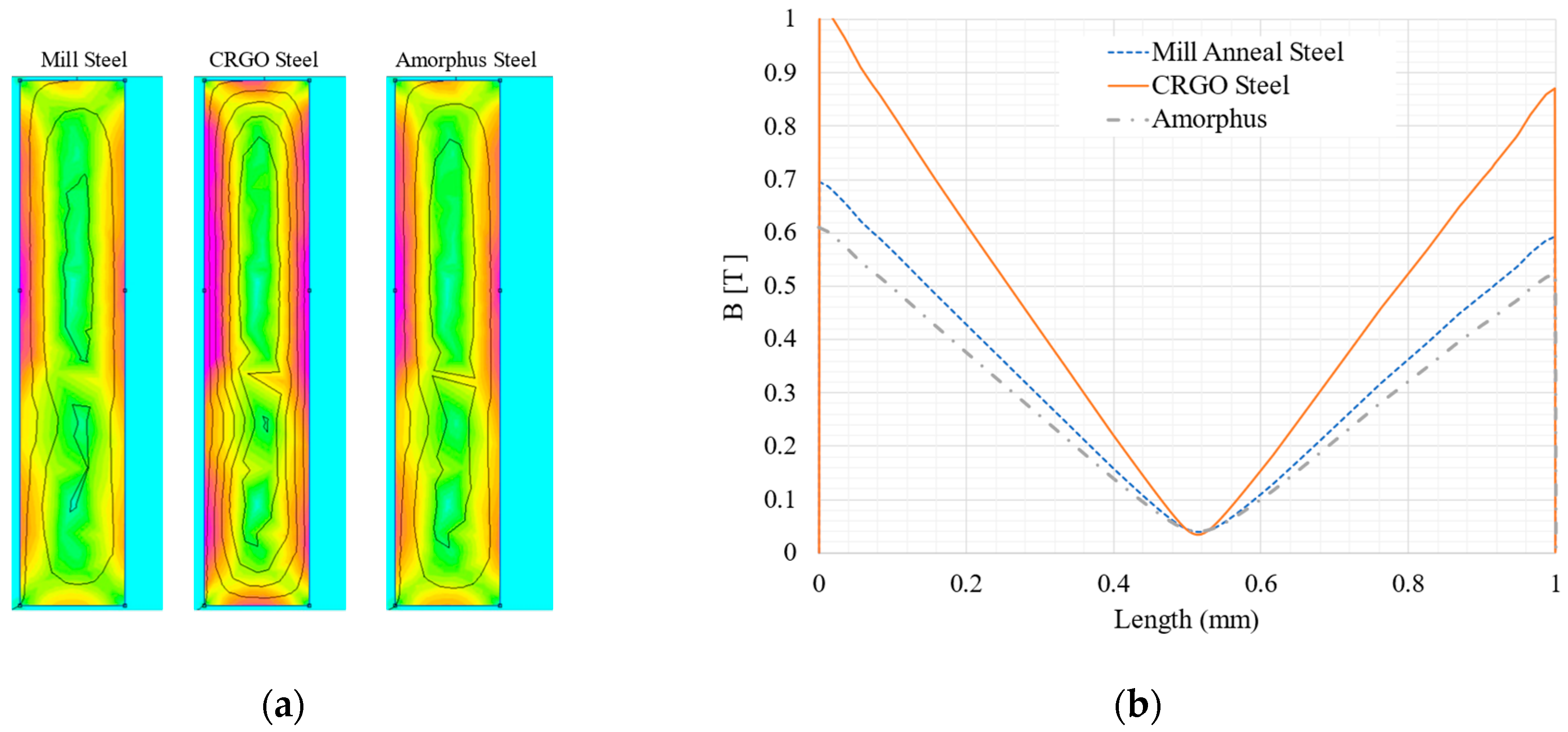
20]. Despite the important technical literature on this topic, in the design stage there are still some technical doubts about how the stray magnetic field is affected when there are different widths and heights of the windings. In the design, it is common and very normal for the thicknesses of the windings to be different and the height of the high voltage winding to be similar to the height of the low voltage winding, but most of the time it is not possible to achieve this, so this work contributes to the analysis and quantification of the effect of these differences in dimensions in the windings on the stray magnetic flux that reaches the tank. Therefore, it helps to have an overview of its magnetic field density, which assists in controlling additional losses. In this work, the characterisation of the magnetic field that reaches the tank walls was added along with a quick-to-apply model to approximately estimate the stray magnetic field from the coil to the limits of the tank walls and the impact of reducing stray losses by placing magnetic shunts and using a shell-type configuration transformer. This work also considers three different materials (Mill Anneal Steel, Grain Oriented Silicon Steel and Amorphous Silicon Steel) for the shunts in order to analyse their effectiveness and cost. Therefore, the objective of this research is to serve as a valuable tool in the design and manufacturing processes of transformers. Therefore, this work has the following main contributions: (1) the development of a technique to perform a quick and accurate estimation of the stray magnetic field and losses of the tank when there is asymmetry in transformer windings; (2) characterisation of the stray magnetic field on the tank walls for a better visualization of shielding placement; and (3) study of the potential reduction in stray losses on tank walls and core clamps, through the adoption of shell-type configurations.


 ,
, 


