

Multiscale Analysis of Membrane-Assisted Integrated Reactors for CO2 Hydrogenation to Dimethyl Ether
 ,
, 
Abstract
:
1. Introduction
1.1. Motivation and Strategic View
1.2. State-of-the-Art and Potential Solutions in Different Scales
1.2.1. Catalyst for CO2 Hydrogenation to Methanol and Its Dehydration to Dimethyl Ether
1.2.2. Hybrid Catalysts for CO2 Hydrogenation to Dimethyl Ether
1.2.3. Membrane: CO2-Dosing and Water Removal
1.2.4. Integrated Reactor and Process Intensification
2. Multi-Scale Analysis
2.1. Catalyst
2.1.1. Material Selection and Synthesis
2.1.2. Catalytic Performance Test for Various Hybrid Catalytic Bed Structures
2.2. Membrane and Material Processing
2.2.1. Membrane Synthesis and Potentials
2.2.2. Membrane Separation Performance: Permeation Study and Screening the Conditions
2.2.3. Membrane Separation Performance: In-Situ Separation in Integrated Reactors
2.3. Evolutionary Analysis of the Integrated Reactor-Separation Systems
2.3.1. Integrated Reactors: Membrane Reactor
2.3.2. Integrated Reactors: Membrane-Assisted Reactive Distillation
2.3.3. Practical Aspects in Fabricating and Operating the Integrated Systems in Large-Scale
3. Conclusions
Author Contributions
Funding
Data Availability Statement
Acknowledgments
Conflicts of Interest
Nomenclature
| Abbreviation | Expression | |
| BET | Brunauer–Emmett–Teller (a model for measuring the specific surface area) | |
| CI | Co-Impregnated Catalyst | |
| CP | Co-Precipitated Catalyst | |
| CZZ | CuO-ZnO/ZSM5 electrospun fibers | |
| DI | Di-Ionized (water) | |
| DME | DiMethyl Ether (Methoxymethane) | |
| EDS | Energy-Dispersive X-ray Spectroscopy | |
| GC | Gas Chromatography | |
| ICP-AES | Inductively Coupled Plasma Atomic Emission Spectroscopy | |
| MeOH | Methanol (CH3OH) | |
| PBMR | Packed Bed Membrane Reactor | |
| SEM | Scanning Electron Microscope | |
| SP | Sequential Precipitated Catalyst | |
| TPAOH | Tetra Propyl Ammonium Hydroxide | |
| TPD | Temperature Programmed Desorption | |
| XRD | X-ray Diffraction | |
| XPS | X-ray photoelectron spectroscopy | |
| Symbol | Description | Unit |
| GHSV | Gas Hourly Space Velocity (under reaction conditions) | h−1 |
| Mw | Molecular weight | g.mol−1 |
| P | Pressure | bar |
| Q | Total flow rate | NmL.min−1 |
| S | Selectivity | % |
| T | Temperature | °C |
| X | CO2 conversion | % |
| X | Mole fraction | - |
| Y | Yield | % |
Appendix A
Appendix A.1. DME Production via Methanol Dehydration in a Reactive Distillation System [19]

Appendix A.2. Simulated Performance of DME Production via Hybrid CO2-Hydrogenation and Methanol Dehydration in an Integrated Reactive Distillation System [28]

References
- IEA. Carbon Capture, Utilisation and Storage; License: CC BY 4.0; IEA: Paris, France, 2022; Available online: https://www.iea.org/reports/carbon-capture-utilisation-and-storage-2 (accessed on 1 August 2023).
- Dziejarski, B.; Krzyżyńska, R.; Andersson, K. Current status of carbon capture, utilization, and storage technologies in the global economy: A survey of technical assessment. Fuel 2023, 342, 127776. [Google Scholar] [CrossRef]
- IEA. CO2 Emissions in 2022; License: CC BY 4.0; IEA: Paris, France, 2023; Available online: https://www.iea.org/reports/co2-emissions-in-2022 (accessed on 1 August 2023).
- Alternative Fuels Data Center. Dimethyl Ether. Available online: https://afdc.energy.gov/fuels/emerging_dme.html (accessed on 11 July 2023).
- Álvarez, A.; Bansode, A.; Urakawa, A.; Bavykina, A.V.; Wezendonk, T.A.; Makkee, M.; Gascon, J.; Kapteijn, F. Challenges in the Greener Production of Formates/Formic Acid, 817 Methanol, and DME by Heterogeneously Catalyzed CO2 Hydrogenation Processes. Chem. Rev. 2017, 117, 9804–9838. [Google Scholar] [CrossRef] [PubMed]
- Godini, H.R.; Kumar, S.R.; Tadikamalla, N.; Gallucci, F. Performance analysis of hybrid catalytic conversion of CO2 to DiMethyl ether. Int. J. Hydrogen Energy 2021, 47, 11341–11358. [Google Scholar] [CrossRef]
- Godini, H.R.; Khadivi, M.; Azadi, M.; Görke, O.; Jazayeri, S.M.; Thum, L.; Schomäcker, R.; Wozny, G.; Repke, J.-U. Multi-Scale Analysis of Integrated C1 (CH4 and CO2) Utilization Catalytic Processes: Impacts of Catalysts Characteristics up to Industrial-Scale Process Flowsheeting, Part I: Experimental Analysis of Catalytic Low-Pressure CO2 to Methanol Conversion. Catalysts 2010, 10, 505. [Google Scholar] [CrossRef]
- Salehi, M.-S.; Askarishahi, M.; Gallucci, F.; Godini, H.R. Selective CO2-Hydrogenation using a membrane reactor. Chem. Eng. Process.-Process. Intensif. 2020, 160, 108264. [Google Scholar] [CrossRef]
- Roy, D.; Mandal, S.C.; Pathak, B. Machine Learning-Driven High-Throughput Screening of Alloy-Based Catalysts for Selective CO2 Hydrogenation to Methanol. ACS Appl. Mater. Interfaces 2021, 13, 56151–56163. [Google Scholar] [CrossRef]
- Ren, M.; Zhang, Y.; Wang, X.; Qiu, H. Catalytic Hydrogenation of CO2 to Methanol: A Review. Catalysts 2022, 12, 403. [Google Scholar] [CrossRef]
- Dang, S.; Yang, H.; Gao, P.; Wang, H.; Li, X.; Wei, W.; Sun, Y. A review of research progress on heterogeneous catalysts for methanol synthesis from carbon dioxide hydrogenation. Catal. Today 2019, 330, 61–75. [Google Scholar] [CrossRef]
- Bateni, H.; Able, C. Development of Heterogeneous Catalysts for Dehydration of Methanol to Dimethyl Ether: A Review. Catal. Ind. 2019, 11, 7–33. [Google Scholar] [CrossRef]
- Liu, C.; Liu, Z. Perspectiveon CO2 Hydrogenation for Dimethyl Ether Economy. Catalysts 2022, 12, 1375. [Google Scholar] [CrossRef]
- Ul-Islam, S. Integrating Green Chemistry and Sustainable Engineering; John Wiley & Sons: Hoboken, NJ, USA, 2019; ISBN 978-1-119-50983-7. [Google Scholar]
- Ateka, A.; Pérez-Uriarte, P.; Gamero, M.; Ereña, J.; Aguayo, A.T.; Bilbao, J. A comparative thermodynamic study on the CO2 conversion in the synthesis of methanol and of DME. Energy 2017, 120, 796–804. [Google Scholar] [CrossRef]
- Rahimalimamaghani, A.; Godini, H.R.; Mboussi, M.; Tanaka, A.P.; Tenco, M.L.; Gallucci, F. Tailored Carbon Molecular Sieve Membranes for Selective CO2 Separation at Elevated Temperatures and Pressures. J. CO2 Util. 2023, 68, 102378. [Google Scholar] [CrossRef]
- Poto, S.; Aguirre, A.; Huigh, F.; Llosa-Tanco, M.A.; Pacheco-Tanaka, D.A.; Gallucci, F.; D’angelo, M.F.N. Carbon molecular sieve membranes for water separation in CO2 hydrogenation reactions: Effect of the carbonization temperature. J. Membr. Sci. 2023, 677, 121613. [Google Scholar] [CrossRef]
- Diban, N.; Urtiaga, A.M.; Ortiz, I.; Ereña, J.; Bilbao, J.; Aguayo, A.T. Influence of the membrane properties on the catalytic production of dimethyl ether with in situ water removal for the successful capture of CO2. Chem. Eng. J. 2013, 234, 140–148. [Google Scholar] [CrossRef]
- US20090048468 & EP2022774; Method for the Production of Dimethyl Ether. European Patent Organisation: Munich, Germany, 2009.
- Francesco, F.; Giuseppe, B.; Catia, C.; Serena, T.; Alessandro, C. Membrane-assisted reactor for the direct conversion of CO2 to DME/MeOH. J. Civ. Eng. Environ. Sci. 2022, 8, 068–070. [Google Scholar] [CrossRef]
- Kumar, S.R. Experimental and Model-Based Analysis of Catalytic CO2-Hydrogenation to Dimethyl Ether. Master’s Thesis, TU Eindhoven, Eindhoven, The Netherlands, 2020. [Google Scholar]
- Tadikamala, N. Experimental Analysis of Carbon Dioxide Hydrogenation to Methanol and Dimethyl Ether (DME). Master’s Thesis, TU Eindhoven, Eindhoven, The Netherlands, 2020. [Google Scholar]
- Tanco, M.A.L.; Tanaka, D.A.P.; Rodrigues, S.C.; Texeira, M.; Mendes, A. Composite-alumina-carbon molecular sieve membranes prepared from novolac resin and boehmite. Part I: Preparation, characterization and gas permeation studies. Int. J. Hydrogen Energy 2015, 40, 5653–5663. [Google Scholar] [CrossRef]
- Tanco, M.A.L.; Tanaka, D.A.P.; Texeira, M.; Mendes, A. Composite-alumina-carbon molecular sieve membranes prepared from novolac resin and boehmite. Part II: Effect of the carbonization temperature on the gas permeation properties. Int. J. Hydrogen Energy 2015, 40, 3485–3496. [Google Scholar] [CrossRef]
- Iliuta, I.; Larachi, F.; Fongarland, P. Dimethyl Ether Synthesis with in situ H2O Removal in Fixed-Bed Membrane Reactor: Model and Simulations. Ind. Eng. Chem. Res. 2010, 49, 6870–6877. [Google Scholar] [CrossRef]
- Available online: https://c2fuel-project.eu (accessed on 1 August 2023).
- Rodriguez-Vega, P.; Ateka, A.; Kumakiri, I.; Vicente, H.; Ereña, J.; Aguayo, A.T.; Bilbao, J. Experimental implementation of a catalytic membrane reactor for the direct synthesis of DME from H2+CO/CO2. Chem. Eng. Sci. 2021, 234, 116396. [Google Scholar] [CrossRef]
- Ayyappan, L. Reactor Integration and Process Intensification for Low-Pressure CO2 DME System. Master’s Thesis, TU Eindhoven, Eindhoven, The Netherlands, 2020. [Google Scholar]
- Hänggi, S.; Elbert, P.; Bütler, T.; Cabalzar, U.; Teske, S.; Bach, C.; Onder, C. A review of synthetic fuels for passenger vehicles. Energy Rep. 2019, 5, 555–569. [Google Scholar] [CrossRef]
- Cholewa, T.; Semmel, M.; Mantei, F.; Güttel, R.; Salem, O. Process Intensification Strategies for Power-to-X Technologies. ChemEngineering 2022, 6, 13. [Google Scholar] [CrossRef]
- Bonura, G.; Todaro, S.; Middelkoop, V.; de Vos, Y.; Abbenhuis, H.; Gerritsen, G.; Koekkoek, A.; Cannilla, C.; Frusteri, F. Effectiveness of the 3D-printing procedure in the synthesis of hybrid catalysts for the direct hydrogenation of CO2 into dimethyl ether. J. CO2 Util. 2023, 70, 102458. [Google Scholar] [CrossRef]
- Godini, H.R.; Prahlad, A.V.; Middelkoop, V.; Görke, O.; Li, S.; Gallucci, F. Electrochemical Surface Treatment for Tailored Porous Structures. Processes 2023, 11, 1260. [Google Scholar] [CrossRef]
- Rohde, M.P. In-Situ H2O Removal via Hydrophilic Membranes during Fischer-Tropsch and other Fuel-Related Synthesis Reactions; Karlsruhe Institute of Technology, Faculty of Chemical and Process Engineering: Karlsruhe, Germany, 2010. [Google Scholar]
- Li, Z.; Deng, Y.; Dewangan, N.; Hu, J.; Wang, Z.; Tan, X.; Liu, S.; Kawi, S. High Temperature Water Permeable Membrane Reactors for CO2 Utilization. Chem. Eng. J. 2021, 420, 129834. [Google Scholar] [CrossRef]
- Kiss, A.A.; Jobson, M.; Gao, X. Reactive Distillation: Stepping Up to the Next Level of Process Intensification. Ind. Eng. Chem. Res. 2019, 58, 5909–5918. [Google Scholar] [CrossRef]


 ; H2O
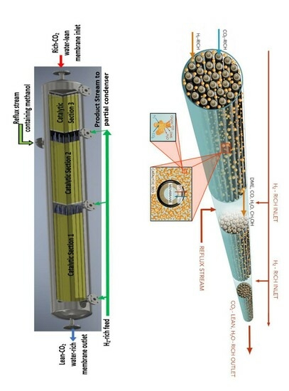
; H2O  ], (c) 3D visualization, (d) multi-pass split-feed reactor operation [Feed 1 and Feed 2 and Feed 3 have the same composition, but could have different flow between the tubes inside the shell; CO2-rich enters inside the tube passes and is collected as CO2-lean at the end of the last pass].
; H2O ], (c) 3D visualization, (d) multi-pass split-feed reactor operation [Feed 1 and Feed 2 and Feed 3 have the same composition, but could have different flow between the tubes inside the shell; CO2-rich enters inside the tube passes and is collected as CO2-lean at the end of the last pass].
], (c) 3D visualization, (d) multi-pass split-feed reactor operation [Feed 1 and Feed 2 and Feed 3 have the same composition, but could have different flow between the tubes inside the shell; CO2-rich enters inside the tube passes and is collected as CO2-lean at the end of the last pass].
; H2O ], (c) 3D visualization, (d) multi-pass split-feed reactor operation [Feed 1 and Feed 2 and Feed 3 have the same composition, but could have different flow between the tubes inside the shell; CO2-rich enters inside the tube passes and is collected as CO2-lean at the end of the last pass].


| Catalyst/Sample | Composition (wt.%) | SBET (m2·g−1) a | Vpore (cm3·g−1) b | Pore Size (nm) c | NH3uptake (µmol·g−1) d |
|---|---|---|---|---|---|
| SI | 16.7% CuO: 16.7% ZnO: 66.6% H-ZSM-5 | 194.5 | 0.17 | 4.5 | 217.7 |
| CP | 33.3% CuO: 33.3% ZnO: 33.3% H-ZSM-5 | 150.5 | 0.33 | 9 | 156.5 |
| CI | 16.7% CuO: 16.7% ZnO: 66.6% H-ZSM-5 | 233.2 | 0.19 | 4.1 | 224.6 |
| SP | 33.3% CuO: 33.3% ZnO: 33.3% H-ZSM-5 | 141.8 | 0.19 | 5.9 | 97.7 |
| Type | Support Pore Size | # of Layers | Diameter | Length | Carbonization Temperature | Polymerization Temperature | Ethylenediamine in Dipping Solution |
|---|---|---|---|---|---|---|---|
| CMSM | 100 nm | 2 | 10 mm | 180 mm | 600 °C | 90 °C | 1.2 wt.% |
Disclaimer/Publisher’s Note: The statements, opinions and data contained in all publications are solely those of the individual author(s) and contributor(s) and not of MDPI and/or the editor(s). MDPI and/or the editor(s) disclaim responsibility for any injury to people or property resulting from any ideas, methods, instructions or products referred to in the content. |
© 2023 by the authors. Licensee MDPI, Basel, Switzerland. This article is an open access article distributed under the terms and conditions of the Creative Commons Attribution (CC BY) license (https://creativecommons.org/licenses/by/4.0/).
Share and Cite
Godini, H.R.; Rahimalimamaghani, A.; Hosseini, S.S.; Bogatykh, I.; Gallucci, F. Multiscale Analysis of Membrane-Assisted Integrated Reactors for CO2 Hydrogenation to Dimethyl Ether. Catalysts 2023, 13, 1273. https://doi.org/10.3390/catal13091273
Godini HR, Rahimalimamaghani A, Hosseini SS, Bogatykh I, Gallucci F. Multiscale Analysis of Membrane-Assisted Integrated Reactors for CO2 Hydrogenation to Dimethyl Ether. Catalysts. 2023; 13(9):1273. https://doi.org/10.3390/catal13091273
Chicago/Turabian StyleGodini, Hamid Reza, Arash Rahimalimamaghani, Seyed Saeid Hosseini, Innokentij Bogatykh, and Fausto Gallucci. 2023. "Multiscale Analysis of Membrane-Assisted Integrated Reactors for CO2 Hydrogenation to Dimethyl Ether" Catalysts 13, no. 9: 1273. https://doi.org/10.3390/catal13091273