

Joint Satellite-Transmitter and Ground-Receiver Digital Pre-Distortion for Active Phased Arrays in LEO Satellite Communications

1
National Space Science Center, Chinese Academy of Sciences, Beijing 100190, China
2
School of Electronic, Electrical and Communication Engineering, University of Chinese Academy of Sciences, Beijing 100049, China
3
Department of Electronic Systems, Aalborg University, 9220 Aalborg, Denmark
*
Author to whom correspondence should be addressed.
Remote Sens. 2022, 14(17), 4319; https://doi.org/10.3390/rs14174319
Submission received: 27 July 2022
/
Revised: 25 August 2022
/
Accepted: 30 August 2022
/
Published: 1 September 2022
(This article belongs to the Topic Advances in Array Signal Processing with Errors: Models, Algorithms and Applications)
Abstract
:A novel joint satellite-transmitter and ground-receiver (JSG) digital pre-distortion (DPD) (JSG-DPD) technique is proposed to improve the linearity and power efficiency of the space-borne active phased arrays (APAs) in low Earth orbit (LEO) satellite communications. Different from the conventional DPD technique that requires a complex RF feedback loop, the DPD coefficients based on a generalized memory polynomial (GMP) model are extracted at the ground-receiver and then transmitted to the digital baseband front-end of the LEO satellite-transmitter via a satellite–ground bi-directional transmission link. The issue of the additive white Gaussian noise (AWGN) of the satellite–ground channel affecting the extraction of DPD coefficients is tackled using a superimposing training sequences (STS) method. The proposed technique has been experimentally verified using a 28 GHz phased array. The performance improvements in terms of error vector amplitude (EVM) and adjacent channel power ratio (ACPR) are 7.5% and 3.6 dB, respectively. Requiring limited space-borne resources, this technique offers a promising solution to achieve APA DPD for LEO satellite communications.
1. Introduction
With the rapid rise of fifth-generation (5G) millimeter-wave (mmWave) communications and broadband low Earth orbit (LEO) satellites [1,2], active phased array (APA) antennas have seen unprecedented development in recent years [3,4,5]. Compared with conventional antennas, APA antennas do not require bulky servo tracking systems. They can change the radiation pattern by adjusting the excitation phases of the antenna elements in the array, thus bringing advantages such as flexible beam control and high reliability [6,7]. Higher power efficiency is required to support high data rates operation while driving power amplifiers (PAs) close to their saturation state will introduce severe nonlinear distortion. Nonlinear distortion leads to non-negligible problems such as: interference to other satellite and terrestrial communication systems due to the increased adjacent channel power ratio (ACPR), and deterioration of the error vector magnitude (EVM) leading to higher bit error rates.
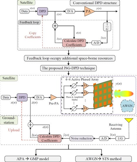
To address this problem, power backoff techniques and digital pre-distortion (DPD) [8,9,10,11,12,13,14] techniques are often adopted, of which DPD techniques have drawn widespread attention because they can better improve power efficiency to fully utilize the space-borne power resources. As shown in Figure 1a,b, the DPD techniques with 4-by-4 array antennas as an example can be further divided into two categories: one is individual DPD [8,9,11], and the other is overall DPD [12,13,14]. The impact of PA nonlinear distortion of a massive multiple-input multiple-output (MIMO) generalized frequency division multiplexing (GFDM) (MIMO-GFDM) system on the spectral shape, the peak to average power ratio (PAPR), and the bit error rate (BER) in the additive white Gaussian noise (AWGN) channel was researched and analyzed in [8]. It proposes a linearization technique for applying each PA pre-distorter separately at the transmitter side of the MIMO-GFDM system. Ref. [9] offers a method to simultaneously compensate for PA nonlinearity, antenna crosstalk, and mismatch in a broadband multi-antenna transmitter. Each transmit path is provided with a dual input DPD, which matches a linear model of the crosstalk and mismatch features of the antenna array shared by all transmitting paths. The DPD technique proposed by [11] includes overall multibeam compensation and separate dual-band compensation. The multibeam compensation deals with multibeam interference, while the dual-band compensation is designed to eliminate the nonlinear distortion of the PA. Nevertheless, these one-to-one DPD techniques are unsuitable for large-scale APAs because of the high complexity and the mutual disturbance between channels.
For large-scale APA linearization, approaches with overall DPD of PAs for all array cells at the transmitter give more generic and effective solutions. The fundamental coefficients of the single-input single-output (SISO) array model include beamforming weights, antenna cross-coupling, channel coefficients, etc. As a result, many sets of trained DPD coefficients are sufficient to reduce the nonlinear distortion of mm-wave radio frequency beamforming array [12]. Ref. [13] assumed that the PAs are similar in all branches, the main beam is generated by collecting the output signal of one PA, and the memory polynomial (MP) model is used to calculate the overall DPD from the main beam and the input of the sub-array. Ref. [14] implements full-angle DPD for 5G mmWave large-scale MIMO transmitters by first compensating for differences of PAs in different transmitter chains and then linearizing the entire subarray using a common digital block. Unfortunately, since the DPD is done within the digital domain before the front-end, these approaches necessitate an RF feedback loop, and the resulting hardware resource consumption is almost equivalent to an space-borne receiver, which is unacceptably high for LEO satellite communications. Therefore, a joint satellite-transmitter and ground-receiver digital pre-distortion (JSG-DPD) technique, by reusing the ground-receiver as the "feedback loop", is proposed in this paper to achieve linearization of the space-borne APA. It is experimentally demonstrated that this technique can dramatically save space-borne resources and can achieve a promising 7.5% EVM improvement. To the best of our knowledge, this paper is the first attempt to join the receiver and transmitter for DPD in order to obtain desirable results with less cost. With the future deployment of a large number of LEO satellite systems, the search for effective high-power-efficient satellite communication techniques becomes increasingly urgent.
2. Principle Analysis of the Proposed JSG-DPD Technique
In this section, we demonstrate the structure of the proposed JSG-DPD technique and present the adopted signal standard, the channel model, and the solution for a low SNR.
2.1. The Proposed JSD-DPD Technique
The proposed system architecture depicted in Figure 2 is mainly based on the overall DPD structure of Figure 1b. However, the space-borne feedback loop is eliminated and replaced by a noise reduction and DPD coefficient extraction system at the ground station to save satellite resources. Certainly, the ground station faces the challenge of a low signal-noise ratio (SNR) resulting from high AWGN. To address this concern, the superimposed training sequences (STS) method is proposed. The nonlinearly compressed STS signals pass through the AWGN channel between the satellite and the ground and are captured by the receiving antenna of the ground station. Noise reduction is performed by exploiting the irrelevancy of the noise, as explained in the following Section 2.4. Then the DPD coefficients of the selected model are calculated with a suitable adaptive algorithm and uploaded to the baseband front-end of the LEO satellite using the satellite–ground bi-directional link. Hence, this joint satellite–ground DPD (JSG-DPD) structure does not occupy additional space-borne resources. It can greatly improve the linearity and the power efficiency of APA, enabling the application of DPD techniques to LEO satellite communications.
2.2. OFDM Technique
Conventional digital modulation is performed on a single carrier, such as QPSK, 16QAM, etc. These single-carrier modulation methods are susceptible to inter-symbol interference (ISI), deteriorating the BER. It is subject to Rayleigh fading in a multipath propagation environment, which can cause burst BER. While orthogonal frequency division multiplexing (OFDM) divides the channel into several orthogonal subchannels in the frequency domain and adopts a subcarrier transmitted in parallel for modulation on each subchannel. In addition, a cyclic prefix is usually inserted between each OFDM symbol as a guard interval. Therefore, the OFDM system offers excellent anti-fading and anti-ISI capabilities, high spectrum efficiency, and is applicable to high-speed digital communication. The mathematical expression for the continuous OFDM baseband signal is
where M represents the number of subcarriers, denotes the information carried on the m-th subcarrier in the u-th OFDM symbol, is the duration of an OFDM symbol, and is the window function. The discrete OFDM baseband signal is derived by sampling the continuous OFDM baseband signal at the Nyquist sampling rate , denoted as
where . In order to enhance the LEO satellite-to-ground data transmission rate, this paper adopts such an OFDM signal with a high PAPR of 11.69 dB
Given that OFDM symbols are composed of several independently modulated subcarrier signals, when each subcarrier is in the same or comparable phase, the superimposed signal will be modulated by the same beginning phase signal, resulting in a huge instantaneous power peak, thus bringing a high PAPR. Since the limited linear operating range of a typical PA, OFDM signals with large PAPR are likely to get into the nonlinear region of the PA, causing serious degradation of the overall system performance.
2.3. LEO Satellite-Ground Channel
As for LEO satellite communications, it is commonly necessary to consider the Doppler effect [15] and multipath effect [16]. The multipath effect is the propagation phenomenon of radio frequency (RF) signals arriving at the receiving antenna through various paths from the transmitting antenna. The electromagnetic waves of each path arrive at the receiver at different times, and thus at different phases. The superposition of multiple signals with different phases at the receiver results in a change in the amplitude of the received signal, which produces the so-called multipath fading.
When considering that the received signal consists of only multipath signal components, the probability density function (PDF) of the signal obeys the Rayleigh distribution
where r and denote the received signal amplitude, and the average multipath power, respectively. While considering the received signal is composed of a line of sight (LOS) signal and multipath signal, the PDF of the signal obeys the Rice distribution
where r indicates the received signal amplitude, z represents the LOS signal amplitude, and is the average multipath power [17]. Generally, we assume ground stations are built in non-urban open areas, thus ignoring the effect of reflections caused by buildings. Due to different atmospheric densities, scattering is typically generated in the troposphere at an altitude of about 10–20 km above the ground. For LEO satellites above several hundred km, such a link length is only 2–3% of the total link length, so the resulting multipath effect is insignificant. In addition, the inter-symbol interference (ISI) from multipath can be maximally eliminated by inserting a guard interval between OFDM symbols, where the guard interval is larger than the maximum multipath delay extension of the satellite communication channel. If the cyclic prefix (CP) is filled in the guard interval, the inter-channel interference (ICI) from multipath can also be avoided. This is the commonly used means of OFDM signal transmission. Therefore, the impact of the multipath effect is ignored in this paper.
When there is relative motion between the satellite and the ground station, the transmitted carrier frequency received by the ground station is frequency shifted, which is the Doppler shift phenomenon. It is harmful to digital communication using correlation demodulation, and thus cannot be ignored. As depicted in Figure 3, the actual velocity of the satellite is v, and the relative speed of the satellite to the ground station is
which varies dynamically. The Doppler shift is defined as
where denotes the carrier frequency, represents the carrier frequency offset, i.e., Doppler frequency offset, and m/s is the speed of light. According to the standard 401.0-B of the Consultative Committee for Space Data Systems (CCSDS) [18], the maximum relative motion speed between a LEO satellite and a ground station is 10 km/s, and the maximum speed change rate is 380 m/s . The maximum Doppler frequency offset of the LEO satellite–ground data transmission system based on Ka-band (28 GHz) is kHz, and the maximum Doppler frequency offset change rate is 35 kHz/s. Therefore, the time-varying Doppler effect makes it difficult for the receiver to accurately track the carrier of the signal, which undoubtedly increases the design difficulty of the receiver. In addition, the Doppler effect causes a spreading/compression of
for a transmitted signal with bandwidth B.
For the Ka-band 100 MHz signal applied in this paper, the maximum spreading of the bandwidth is 3.3 kHz. Given that the time-varying Doppler effect has been solved by mature techniques [19,20,21,22], so it is not the focus of our study. Consequently, the LEO satellite–ground transmission channel is modeled as an AWGN channel in this paper. The magnitude of white Gaussian noise follows a Gaussian distribution, while the power spectral density (PSD) obeys a uniform distribution.
2.4. Noise Reduction Method
The transmission frame structure of the proposed superimposing training sequences method is illustrated in Figure 4, which mainly consists of three parts: frame header, data block, and pilot signal. The pilot signal is composed of H identical training sequences. Assume that the discrete OFDM signal subject to AWGN interference is
where and denote the discrete OFDM signal and the noise signal, respectively. After superimposing the above equation for H times, we obtain
Since AWGN is not only irrelevant between random variables at any two distinct moments, it is also statistically independent. Hence, the noise part is almost zero, while the signal part is amplified H times, and the above equation is then averaged and divided by H on both sides to yield
When the number H of superpositions is large enough, theoretically , . With this method, the valuable signal is coherent and can be accumulated, while the noise signal is irrelevant and cannot be gathered. Therefore, the SNR of the received signal is improved by increasing the signal power, which can be equivalent to noise reduction. Moreover, the frame length and the propagation time occupied by the pilot signal consisting of the superimposed training sequence, etc., can be acceptable during several minutes of LEO satellite data transmission.
3. DPD Coefficients Recognition Algorithm
In this section, we present an indirect learning structure based on the proposed JSG-DPD technique, focusing on the principle of computing the DPD coefficients of the GMP model using the least squares (LS) algorithm.
3.1. The JSG-DPD Indirect Learning Structure
In [28], the indirect learning architecture applied to PA linearization is proposed for the first time. As shown in Figure 5, in the field of satellite communications, the feedback loop for coefficient calculation is almost equivalent to a receiver that would be included in the satellite-transmitter. Therefore, the required cost is unacceptable for satellites; it is also for this reason that dynamic DPD techniques are not widely used in satellite communications. Ref. [29] provides a fifth order static DPD, which means that only the static nonlinearity of the PA can be handled, while the memory effect is ignored. Such a static DPD method would not improve the performance a lot, especially for broadband signals.
The indirect learning structure of the proposed JSG-DPD technique is illustrated in Figure 6, in which the pre-distorter is not working until the DPD coefficients are identified. At this time, the input signal of the APA , is taken as the expected output signal of the DPD coefficients estimation module, and the signal after noise reduction of the received signal is taken as the input of the pre-distortion coefficients estimation module, where G is the gain of the pre-PA and linear APA. The signal is passed through the DPD coefficients estimation module (i.e., post-distortion) to obtain the output signal , which is subtracted from the desired output signal to obtain the error signal . The adaptive discrimination algorithm obtains the coefficients w of the optimal DPD coefficients estimation module by iterating the error signal. Finally, the coefficient w is directly copied as the coefficient of the pre-distorter to make the pre-distorter operate. It is worth pointing out that for the general Volterra system, the P-order post-inverse is the same as the P-order pre-inverse [30]. Thus, for our application, the post-distortion response is the same as the pre-distortion response, and that is why the coefficients can be copied directly to the pre-distorter before the APA. In addition, the Volterra series are generalized nonlinear models with memory, and DPD of Volterra models is usually implemented using P-order inverse techniques [31].
Notably, another communication link is not required because the pilot signal is only a fixed segment of the signal known to the ground station for the purpose of calculating the DPD coefficients. Therefore, the proposed JSG-DPD indirect learning structure does not occupy additional space-borne resources.
The calculation of the DPD coefficients is very fast after the ground station receives the pilot signal, and this calculation time is even negligible because the computing resources of the ground station are very powerful. Instead, the time to be concerned is the time to upload the DPD coefficients, which depends on the communication rate of the uplink. For this paper, the number of coefficients of the generalized memory polynomial model obtained is several tens, which can be uploaded in a short time (ms level).
Therefore, both the DPD coefficient calculation time and the DPD coefficient upload time are very short and do not illegally emit large amounts of spurious emissions to other satellites, which can affect the communication quality.
It is only possible that while waiting for the coefficients to be uploaded, the received signal quality of the ground station will degrade because the space-borne DPD coefficients have not been updated yet. After the coefficients are uploaded and the DPD coefficients are updated, the received signal quality at the ground station will be greatly improved. There is a mode that can be set to avoid the problem of temporary degradation of communication quality: when the received signal quality degrades, only the pilot signal used for updating DPD coefficients is transmitted. Normal scientific data will be transmitted after the DPD coefficients have been updated. Hence, although it takes time to upload DPD coefficients, it is not required for each transition, and the number of uploaded coefficients is extremely small.
3.2. Generalized Memory Polynomial (GMP) Model
For narrow-band signals, where the memory effect is not obvious, it can usually be implemented using polynomial models, Saleh models [32], etc. For wideband signals, the influence of the memory effect cannot be ignored, and the output signal of the APA is not only related to the current input signal, but also related to the past input signal, so it is necessary to use a nonlinear model with memory for wideband APA modeling. Memory models mainly include Volterra series models [33] and their simplified forms, such as memory polynomial (MP) [28], generalized memory polynomial (GMP) [34], Wiener model [35], Hammerstein model [36], etc. Recently, neural network models [37] have also been investigated for modeling nonlinear systems.
Usually, the MP model and Volterra series are used to model narrowband memory APAs and wideband memory APAs, respectively. While the coefficients of Volterra series model are too complex and the coefficients of MP model are too simplified. As a compromise, the GMP model can achieve better modeling results than the MP model by considering the generalized memory effect and the number of coefficients can be acceptable for LEO satellite communication.
The significance of the APA behavior model is that it can inverse model the APA and be used to compensate for the signal distortion caused by the APA nonlinearity. In this broadband OFDM signal and array antennas for the LEO satellite communication application scenario, it is necessary to trade off the computational complexity and algorithm performance. The MP model is a simplified form of Volterra for narrowband signals as well as unit antenna systems with few model coefficients. The MP model with nonlinear order K and memory depth Q can be written as
where and are the input and output signals of the model, and represents the coefficients of the model. The total number of coefficients is .
Its performance is limited because it contains only the diagonal terms of Volterra. While in some application scenarios, non-diagonal terms can significantly impact the model accuracy. Although the neural network model is very flexible and adaptable, the large number of coefficients requires a large number of space-borne computing resources, so it cannot be deployed on satellites by far. The GMP model performs better for strongly nonlinear dynamical systems because it supplements the consideration of generalized memory effects than the MP model. Therefore, the GMP model is adopted as the model of pre-distorter in this paper
where and are the input and output signals of the model, , , and represent the model coefficients of the MP sub-model, the lagging term, and the leading term, respectively. , , and stand for the nonlinear order of each branch term, , , and denote the memory depth of each branch term, and , are the additional degrees of freedom, which determine the maximum selectable range of memory depths for the lagging and leading terms, respectively. The total number of coefficients is .
3.3. Coefficient Estimation Algorithm
Classical adaptive estimation algorithms include the LS algorithm, the least mean square (LMS) algorithm, and the recursive least squares (RLS) algorithm. These methods are also widely applied in adaptive equalization [38,39]. The LMS algorithm has the advantages of no matrix inversion, simple structure, and easy implementation. Still, it is unsuitable for DPD application scenarios since it is prone to poorly conditioned covariance matrices, resulting in extremely slow convergence. The RLS algorithm is more computationally intensive and may also have poorly conditioned covariance matrices leading to unstable convergence. Therefore, in this paper, we employ the batch processing LS algorithm to estimate model coefficients.
The core idea of the LS algorithm is to search for the best function of the data for matching by minimizing the sum of squares of the errors. By replacing and of Equation (13) with and , respectively, we can write the equation as
where
where are the parameters of the GMP model, and the LS solution of Equation (14) is
where denotes the complex conjugate transpose of the matrix, and is the estimated GMP coefficients (including ). With such an approach, the APA and DPD coefficients of the GMP model can be obtained based on the corresponding input and output data.
In addition, it is worth noting that the GMP model has as many as eight parameters, while the MP model has only two. Parameter selection is usually performed scan-by-scan to obtain a set of parameters to achieve a trade-off between the modeling error and model size. This approach is appropriate for the MP model, but for the GMP model with eight parameters, it takes a lot of combinations and time to obtain the proper set of parameters. There have been studies, such as the simulated annealing (SA) method, the particle swarm optimization with the Akaike information criterion (PSO-AIC) method [40], to develop fast and efficient strategies to determine the optimal parameters, allowing a suitable balance of performance and computing complexity.
4. Experimental Validation and Results Analysis
In this section, the experimental system is presented, followed by the determination of the training sequence length and the analysis of the JSG-DPD results for two power levels.
4.1. Experimental Setup
The structural block diagrams of the over-the-air (OTA) measurement equipment and the actual laboratory equipment photo are presented in Figure 7 and Figure 8, respectively. The 5G new radio (NR) intermediate frequency (IF) signal with a bandwidth of 100 MHz centered at 3 GHz is generated from a vector signal generator (VSG)(R&S SMBV100B). The Agilent E3247C outputs an unmodulated signal of 12.5 GHz, which is multiplied to 25 GHz by a MITEQ-MAX2M200400 frequency multiplier, and then sent to a power divider as a local oscillator (LO) signal for the up-converter (KTX321840) and down-converter (KRX321840). The 28 GHz bandpass filtered signal is linearly amplified by a pre-amplifier (Ducommum APH-26063325) away from its saturation region to drive the APA into its compression state. The APA device is based on the Amotech AAiPK428GC-A0404, which consists of four Anokiwave AWMF-0158 transceivers and incorporates 16 branches attenuators, phase shifters, and PAs in a 4-by-4 APA, as well as 16 patch antennas. The main beam signal is captured by an observation horn antenna. After down-conversion to IF, it is collected and converted to a baseband signal by an R&S FSW spectrum analyzer. Lastly, the baseband signal is processed by MATLAB.
4.2. Experimental Results and Analysis
Generally, to obtain higher drain efficiency, the PA is required to operate in 2–3 dB gain compression; thus, we choose two input power levels of −24 dBm and −25 dBm from VSG for testing. The nonlinear characteristics of such points are meaningful and significantly impact the quality of the transmitted signal without DPD techniques.
For the JSG-DPD technique proposed in this paper, it is necessary to trade-off the model performance and the frame length occupation to select a suitable length of training sequences to model and linearize the APA. Therefore, we first conduct experiments in the noiseless scenario to determine the length of training sequences by observing the improvement of ACPR and EVM. The expression of ACPR and EVM are as follows
where , are the signal power of the left channel and the right channel adjacent to the main channel, respectively, and is the power of the signal of the main channel (transmit channel).
where the vector error signal , , are the expected signal’s quadrature components, and , are the two quadrature signals of the real measurement, respectively.
Since this part of the test is performed at the ground station (before the satellite launch), the prior knowledge about APA and an almost noise-free experimental scenario can be obtained. The experimental results are shown in Figure 9. For these two input power levels, the improvement of both ACPR and EVM is optimal for a training sequence length of 40,000. Although the EVM improvement may be better after the training length exceeds 100,000, an extra-long frame length is needed to obtain a slight improvement. Especially after hundreds or thousands of superpositions, the slight performance improvement is negligible in comparison to the cost of the frame length. Hence, the training sequence length is chosen to be 40,000 after a trade-off.
In order to verify the effect of AWGN on the transmitted signal without loss of generality, an SNR of 10 dB is assumed for each satellite transit to establish communication with the ground station.
In actual communication scenarios, as shown in Figure 10, when the angle between the satellite and the ground station is 5 degrees from the horizontal, the communication is established, and the communication distance is the longest and the SNR is the smallest. It is at this moment that our proposed method starts to operate. The relative position between transceivers will change, which will lead to fluctuations in SNR. The SNR variation throughout the communication window may exceed 10 dB [41], but our proposed method is only used when communication is just established. The SNR fluctuation range is approximately 10 dB to 10.5 dB, which is not a large enough fluctuation to affect the experimental results. Therefore, for the convenience of the calculation, we assume a constant SNR of 10 dB.
The unprocessed received signal at this point is shown in Figure 11a, and the critical sidelobe information of the APA nonlinear system is completely drowned in the noise. After 10, 100, and 1000 superimposed training sequences, the sidelobe information is gradually revealed. As the time domain signal results shown in Figure 11b, the noise reduction processed signal and the original signal almost overlap. Hence, the nonlinear characteristics of the APA system can be extracted.
According to the DPD structure introduced in the previous sections, the GMP model is applied to model the APA system and generate the predistorted signal. Figure 12 shows the AM-AM and AM-PM curves of this APA system. The predistorted signal forms an inverse relationship with the original APA output signal, which makes the combined pre-distorter and the APA approximately linear. The time-domain signal comparison in Figure 13 reveals that the most effective strategy of the DPD technique is to pre-amplify the signal at high amplitude so that after the nonlinear APA gain compression, the same linear gain can be achieved as at other low amplitude.
Empirically and based on several attempts to obtain the minimum normalized mean square error (NMSE)
where is the actual output of the APA, and is the output of the APA obtained by model fitting. Thus, the optimal parameters selected for the GMP model are 3, 5, 2, 3, 2, 3, 2, 2, which represent the nonlinear order and memory depth of the MP sub-model, lagging envelope term, and leading envelope term, as well as the additional degrees of freedom of the lagging and leading term. In this paper, experiments were also conducted on the MP model for comparison. For fairness, the nonlinear order and memory depth were chosen as three and five, respectively, which are consistent with the MP sub-model of the GMP model. As can be seen from the results in Figure 14 and Table 1, for the case of stronger nonlinearity (input power level: −24 dBm), the application of the proposed JSG-DPD method improves the upper and lower ACPR average performance by nearly 4 dB for a training sequence superposition of 1000 or 100 times with the GMP model, especially the EVM performance by more than 7.5%, which undoubtedly enhances the quality of the transmitted signal significantly. The ground station is more concerned about the improvement status of EVM than ACPR. When the number of training sequence superposition is 10, there is also an improvement of nearly 6.5% in EVM, which is still promising. In contrast, the results without the STS method improved the EVM slightly. In addition, for the results of the MP model, the improvement in EVM is not as good as that of the GMP model, with a difference of about 0.2% to 0.4%. Nevertheless, it is noteworthy that using the MP model without the STS method still improves the ACPR by 2.5 dB, while the ACPR results with the GMP model without the STS method have deteriorated to the extent that it seriously affects the signal transmission in the adjacent channels.
For the case of slightly weaker nonlinearity (input power level: −25 dBm), applying the proposed JSG-DPD method, the EVM performance is improved by 6.3% to 6.9% for the training sequence superpositions of 1000, 100, and 10 times with the GMP model. For the results of the MP model, the improvement of EVM is not as good as that of the GMP model, and the difference is about 0.2–0.8%. Moreover, the MP model is still more robust than the GMP model for ACPR improvement, which might depend on its low number of parameters and insensitivity to low SNR responses.
In summary, the problem of low SNR due to AWGN channels can be effectively solved after 1000 or 100 times of superimposed training sequences. For the 10 to 15 min of LEO satellite transit, the pilot sequence length of 40,000 times 1000 or 100 is acceptable, accounting for less than 1 min. More critically, it is not necessary to re-adjust the DPD coefficients for each transit. However, only when the communication quality degrades significantly and the BER of the ground station crosses the preset threshold. It is at this point that the DPD coefficients are re-adjusted based on the operational status of the space-borne APA using the proposed JSG-DPD technique to restore the normal transmission state, allowing the linearity and power efficiency of the space-borne APA to be enhanced without taking any additional space-borne resources. Although the STS method used in this paper to improve SNR appears simple, it validates the feasibility of the proposed JSG-DPD technique. There is still a lot of room for further exploration and performance improvement, such as adopting deep learning approaches.
5. Conclusions
In this paper, a joint satellite-transmitter and ground-receiver (JSG) digital pre-distortion (DPD) (JSG-DPD) technique is proposed to linearize a low Earth orbit (LEO) space-borne active phased array (APA). The method takes the approach of DPD coefficients extraction at the ground station, which saves a complete set of feedback loop at the satellite-transmitter side compared to the conventional DPD techniques. The issue of sidelobe information drowning in the additive white Gaussian noise (AWGN) is addressed by employing the superimposed training sequences (STS) method. The proposed method is experimentally verified to improve the adjacent channel power ratio (ACPR) by 4 dB, especially the error vector amplitude (EVM) greatly by 7.5%. In addition, the performance difference between the GMP model and the MP model is analytically compared. The proposed technique provides a feasible means for the linearization of space-borne power amplifiers (PAs) or APAs. In the future, we will address the problem of accurate synchronization of training sequences and seek opportunities for in-orbit validation in actual LEO satellite communication projects.
Author Contributions
Conceptualization, Q.C. and Z.W.; methodology, Q.C.; software, Q.C.; validation, Q.C.; formal analysis, Q.C. and M.S.; investigation, Q.C.; resources, Q.C.; data curation, Q.C.; writing—original draft preparation, Q.C.; writing—review and editing, Q.C., Z.W., G.F.P. and M.S.; visualization, Q.C.; supervision, Z.W., G.F.P. and M.S.; project administration, Z.W., G.F.P. and M.S. All authors have read and agreed to the published version of the manuscript.
Funding
This research was funded by China Scholarship Council, grant number 202104910442.
Data Availability Statement
Not applicable.
Conflicts of Interest
The authors declare no conflict of interest.
References
- Su, Y.; Liu, Y.; Zhou, Y.; Yuan, J.; Cao, H.; Shi, J. Broadband LEO Satellite Communications: Architectures and Key Technologies. IEEE Wirel. Commun. 2019, 26, 55–61. [Google Scholar] [CrossRef]
- Leyva-Mayorga, I.; Soret, B.; Röper, M.; Wübben, D.; Matthiesen, B.; Dekorsy, A.; Popovski, P. LEO Small-Satellite Constellations for 5G and Beyond-5G Communications. IEEE Access 2020, 8, 184955–184964. [Google Scholar] [CrossRef]
- Hong, W.; Jiang, Z.H.; Yu, C.; Zhou, J.; Chen, P.; Yu, Z.; Zhang, H.; Yang, B.; Pang, X.; Jiang, M.; et al. Multibeam Antenna Technologies for 5G Wireless Communications. IEEE Trans. Antennas Propag. 2017, 65, 6231–6249. [Google Scholar] [CrossRef]
- Kumar, B.P.; Kumar, C.; Kumar, V.S.; Srinivasan, V.V. Reliability Considerations of Spherical Phased Array Antenna for Satellites. IEEE Trans. Aerosp. Electron. Syst. 2018, 54, 1381–1391. [Google Scholar] [CrossRef]
- You, D.; Takahashi, Y.; Takeda, S.; Moritani, M.; Hagiwara, H.; Koike, S.; Lee, H.; Wang, Y.; Li, Z.; Pang, J.; et al. A Ka-Band 16-Element Deployable Active Phased Array Transmitter for Satellite Communication. In Proceedings of the 2021 IEEE MTT-S International Microwave Symposium (IMS), Atlanta, GA, USA, 6–11 June 2021; pp. 799–802. [Google Scholar] [CrossRef]
- Moon, S.M.; Yun, S.; Yom, I.B.; Lee, H.L. Phased Array Shaped-Beam Satellite Antenna With Boosted-Beam Control. IEEE Trans. Antennas Propag. 2019, 67, 7633–7636. [Google Scholar] [CrossRef]
- Li, X.; Wang, J.; Li, Z.; Li, Y.; Chen, M.; Zhang, Z.; Geng, Y. Leaky-Wave Antenna Arrays for Flexible Dual-Beam Switching. IEEE Trans. Antennas Propag. 2021, 69, 8376–8386. [Google Scholar] [CrossRef]
- Jayati, A.E.; Wirawan; Suryani, T.; Endroyono. Nonlinear Distortion Cancellation using Predistorter in MIMO-GFDM Systems. Electronics 2019, 8, 620. [Google Scholar] [CrossRef]
- Hausmair, K.; Landin, P.N.; Gustavsson, U.; Fager, C.; Eriksson, T. Digital Predistortion for Multi-Antenna Transmitters Affected by Antenna Crosstalk. IEEE Trans. Microw. Theory Tech. 2018, 66, 1524–1535. [Google Scholar] [CrossRef]
- Li, P.; Zhang, Y.; Yao, J. Rapid Linear Frequency Swept Frequency-Modulated Continuous Wave Laser Source Using Iterative Pre-Distortion Algorithm. Remote Sens. 2022, 14, 3455. [Google Scholar] [CrossRef]
- Wu, Q.; Jing, J.; Zhu, X.W.; Yu, C. Digital Predistortion for Concurrent Dual-band Millimeter Wave Analog Multibeam Transmitters. IEEE Trans. Circuits Syst. II Express Briefs 2021, 69, 1747–1751. [Google Scholar] [CrossRef]
- Ng, E.; Beltagy, Y.; Scarlato, G.; Ben Ayed, A.; Mitran, P.; Boumaiza, S. Digital Predistortion of Millimeter-Wave RF Beamforming Arrays Using Low Number of Steering Angle-Dependent Coefficient Sets. IEEE Trans. Microw. Theory Tech. 2019, 67, 4479–4492. [Google Scholar] [CrossRef]
- Liu, X.; Chen, W.; Chen, L.; Ghannouchi, F.M.; Feng, Z. Power Scalable Beam-Oriented Digital Predistortion for Compact Hybrid Massive MIMO Transmitters. IEEE Trans. Circuits Syst. I Regul. Pap. 2020, 67, 4994–5006. [Google Scholar] [CrossRef]
- Yu, C.; Jing, J.; Shao, H.; Jiang, Z.H.; Yan, P.; Zhu, X.W.; Hong, W.; Zhu, A. Full-Angle Digital Predistortion of 5G Millimeter-Wave Massive MIMO Transmitters. IEEE Trans. Microw. Theory Tech. 2019, 67, 2847–2860. [Google Scholar] [CrossRef]
- Khan, T.A.; Afshang, M. A Stochastic Geometry Approach to Doppler Characterization in a LEO Satellite Network. In Proceedings of the ICC 2020—2020 IEEE International Conference on Communications (ICC), Dublin, Ireland, 7–11 June 2020; pp. 1–6. [Google Scholar] [CrossRef]
- Hou, Y.; Xiong, H.; Xiang, H.; Ma, B.; Xiong, J. Simulation Analysis of Multipath Fading Channel Characteristics in Satellite Communication System. In Proceedings of the 2019 IEEE 3rd Advanced Information Management, Communicates, Electronic and Automation Control Conference (IMCEC), Chongqing, China, 11–13 October 2019; pp. 1367–1370. [Google Scholar] [CrossRef]
- Liu, T.; Sun, B.; Li, Z.; Dou, Z. Analysis of channel characteristics and channel model for satellite communication system. In Proceedings of the 2016 IEEE International Conference on Electronic Information and Communication Technology (ICEICT), Harbin, China, 20–22 August 2016; pp. 166–169. [Google Scholar] [CrossRef]
- CCSDS. 401.0-B-29, Radio Frequency and Modulation Systems—Part 1 Earth Stations and Spacecraft; CCSDS: Washington, DC, USA, 2019. [Google Scholar]
- Jiang, W.; Yang, X.; Tong, F.; Yang, Y.; Zhou, T. A Low-Complexity Underwater Acoustic Coherent Communication System for Small AUV. Remote Sens. 2022, 14, 3405. [Google Scholar] [CrossRef]
- Li, J.; Zhang, Y.; Zhang, Y.; Xiong, W.; Huang, Y.; Wang, Z. Fast tracking Doppler compensation for OFDM-based LEO Satellite data transmission. In Proceedings of the 2016 2nd IEEE International Conference on Computer and Communications (ICCC), Chengdu, China, 14–16 October 2016; pp. 1814–1817. [Google Scholar] [CrossRef]
- Khan, M.B.; Hussain, A.; Anjum, U.; Babar Ali, C.; Yang, X. Adaptive Doppler Compensation for Mitigating Range Dependence in Forward-Looking Airborne Radar. Electronics 2020, 9, 1896. [Google Scholar] [CrossRef]
- Ming, L.; Lin, Z.; Yide, Z. A novel Doppler frequency shift compensation algorithm for OFDM underwater acoustic communication system. In Proceedings of the 2013 25th Chinese Control and Decision Conference (CCDC), Guiyang, China, 25–27 May 2013; pp. 1571–1575. [Google Scholar] [CrossRef]
- Zhang, X.; Ying, W.; Yang, P.; Sun, M. Parameter estimation of underwater impulsive noise with the Class B model. IET Radar Sonar Navig. 2020, 14, 1055–1060. [Google Scholar] [CrossRef]
- Mahmood, A.; Chitre, M. Modeling colored impulsive noise by Markov chains and alpha-stable processes. In Proceedings of the OCEANS 2015-Genova, Genova, Italy, 18–21 May 2015; pp. 1–7. [Google Scholar]
- Wei, G.f.; Jian, T.; Qiu, R.j. Signal denoising via median filter & wavelet shrinkage based on heavy-tailed modeling. In Proceedings of the 2006 8th International Conference on Signal Processing, IEEE, Guilin, China, 16–20 November 2006; Volume 1. [Google Scholar]
- Hamza, A.B.; Krim, H. Nonlinear image filtering in a mixture of Gaussian and heavy-tailed noise. In Proceedings of the 11th IEEE Signal Processing Workshop on Statistical Signal Processing (Cat. No. 01TH8563), IEEE, Singapore, 6–8 August 2001; pp. 90–93. [Google Scholar]
- Vishwakarma, D.; Kapoor, R.; Dhiman, A.; Goyal, A.; Jamil, D. De-noising of Audio Signal using Heavy Tailed Distribution and comparison of wavelets and thresholding techniques. In Proceedings of the 2015 2nd International Conference on Computing for Sustainable Global Development (Indiacom), IEEE, New Delhi, India, 11–13 March 2015; pp. 755–760. [Google Scholar]
- Ding, L.; Zhou, G.; Morgan, D.; Ma, Z.; Kenney, J.; Kim, J.; Giardina, C. A robust digital baseband predistorter constructed using memory polynomials. IEEE Trans. Commun. 2004, 52, 159–165. [Google Scholar] [CrossRef]
- Wertz, P.; Hespeler, B.; Kiessling, M.; Hagmanns, F.J. Next generation high data rate downlink subsystems based on a flexible APSK modulator applying SCCC encoding. In Proceedings of the 2016 International Workshop on Tracking, Telemetry and Command Systems for Space Applications (TTC), Noordwijk, The Netherlands, 13–16 September 2016; pp. 1–7. [Google Scholar]
- Schetzen, M. Theory of pth-order inverses of nonlinear systems. IEEE Trans. Circuits Syst. 1976, 23, 285–291. [Google Scholar] [CrossRef]
- Schetzen, M. The Volterra and Wiener Theories of Nonlinear Systems; John Wiley & Sons: Hoboken, NJ, USA, 1980; pp. 199–208. [Google Scholar]
- Liu, H.y.; Wang, Y.y. Adaptive predistorter based oninverse saleh function and saleh model. In Proceedings of the 2010 2nd International Conference on Advanced Computer Control, Shenyang, China, 27–29 March 2010; Volume 2, pp. 151–154. [Google Scholar] [CrossRef]
- Crespo-Cadenas, C.; Madero-Ayora, M.J.; Becerra, J.A. A bivariate Volterra series approach to modeling and linearization of power amplifiers. In Proceedings of the 2021 IEEE Topical Conference on RF/Microwave Power Amplifiers for Radio and Wireless Applications (PAWR), Virtual Conference, 17–22 January 2021; pp. 4–7. [Google Scholar] [CrossRef]
- Morgan, D.; Ma, Z.; Kim, J.; Zierdt, M.; Pastalan, J. A Generalized Memory Polynomial Model for Digital Predistortion of RF Power Amplifiers. IEEE Trans. Signal Process. 2006, 54, 3852–3860. [Google Scholar] [CrossRef]
- Abd-Elrady, E. Digital predistortion of wiener systems using the nonlinear filtered-x PEM algorithm with initial subsystem estimates. In Proceedings of the 2016 IEEE 59th International Midwest Symposium on Circuits and Systems (MWSCAS), Abu Dhabi, United Arab Emirates, 16–19 October 2016; pp. 1–4. [Google Scholar] [CrossRef]
- Liu, X.; Chen, W.; Feng, Z. Broadband Digital Predistortion Utilizing Parallel Quasi- Wiener-Hammerstein Model with Extended Dynamic Range. In Proceedings of the 2021 IEEE MTT-S International Wireless Symposium (IWS), Harbin, China, 12–15 August 2021; pp. 1–3. [Google Scholar] [CrossRef]
- Louliej, A.; Jabrane, Y.; Jiménez, V.P.G.; Guilloud, F. Dimensioning an FPGA for Real-Time Implementation of State of the Art Neural Network-Based HPA Predistorter. Electronics 2021, 10, 1538. [Google Scholar] [CrossRef]
- Li, J.; Lim, C.; Nirmalathas, A. Indoor Optical Wireless Communications using Few-mode Based Uniform Beam Shaping and LMS Based Adaptive Equalization. In Proceedings of the 2020 IEEE Photonics Conference (IPC), Vancouver, BC, Canada, 28 September–1 October 2020; pp. 1–2. [Google Scholar] [CrossRef]
- Zeeshan, M.; Khan, M.W. Adaptive equalization in hybrid DS-TH CDMA system using State-Space RLS with Adaptive Memory. In Proceedings of the 2017 IEEE 2nd International Conference on Opto-Electronic Information Processing (ICOIP), Singapore, 7–9 July 2017; pp. 11–15. [Google Scholar] [CrossRef]
- Abdelhafiz, A.; Behjat, L.; Ghannouchi, F.M. Generalized Memory Polynomial Model Dimension Selection Using Particle Swarm Optimization. IEEE Microw. Wirel. Components Lett. 2018, 28, 96–98. [Google Scholar] [CrossRef]
- Chen, Q.; Zhang, Y.; Jalili, F.; Wang, Z.; Huang, Y.; Wang, Y.; Liu, Y.; Pedersen, G.F.; Shen, M. Robust Digital Signal Recovery for LEO Satellite Communications Subject to High SNR Variation and Transmitter Memory Effects. IEEE Access 2021, 9, 135803–135815. [Google Scholar] [CrossRef]
Figure 1.
Block diagram of DPD structure of conventional two categories of array antennas: (a) one-to-one DPD; (b) overall DPD.
Figure 1.
Block diagram of DPD structure of conventional two categories of array antennas: (a) one-to-one DPD; (b) overall DPD.

Figure 2.
The system architecture of the proposed JSG-DPD technique.

Figure 3.
Schematic diagram of the distance variation of LEO satellite–ground data transmission link.
Figure 3.
Schematic diagram of the distance variation of LEO satellite–ground data transmission link.

Figure 4.
Data transmission frame structure with noise reduction function.

Figure 5.
The conventional DPD indirect learning architecture.

Figure 6.
The indirect learning structure of the proposed JSG-DPD technique.

Figure 7.
Schematic diagram of the experimental setup.

Figure 8.
The LAB picture of the measurement setup.

Figure 9.
Improvement results of ACPR and EVM for different input power levels from VSG: (a) : −25 dBm; (b) : −24 dBm.
Figure 9.
Improvement results of ACPR and EVM for different input power levels from VSG: (a) : −25 dBm; (b) : −24 dBm.

Figure 10.
The communication window occupied by the proposed method.

Figure 11.
Frequency and time domain noise reduction results with STS method: (a) frequency domain; (b) Time domain.
Figure 11.
Frequency and time domain noise reduction results with STS method: (a) frequency domain; (b) Time domain.

Figure 12.
Measured AM-AM and AM-PM curves with the proposed technique for 100 MHz OFDM signal: (a) AM-AM; (b) AM-PM.
Figure 12.
Measured AM-AM and AM-PM curves with the proposed technique for 100 MHz OFDM signal: (a) AM-AM; (b) AM-PM.

Figure 13.
Time domain indication of the pre-distorted signal.

Figure 14.
Measured normalized PSD with different methods for different input power levels from VSG: (a) : −25 dBm; (b) : −24 dBm.
Figure 14.
Measured normalized PSD with different methods for different input power levels from VSG: (a) : −25 dBm; (b) : −24 dBm.


Table 1.
Measured ACPR and EVM results with different methods for different input power levels from VSG.
Table 1.
Measured ACPR and EVM results with different methods for different input power levels from VSG.
| Power Level | : −25 dBm | : −24 dBm | ||
|---|---|---|---|---|
| Scheme | ACPR (dBc) Lower & Upper | EVM | ACPR (dBc) Lower & Upper | EVM |
| Original signal (APA input) | −45.48/−45.93 | – | −45.48/−45.93 | – |
| Original signal (APA output) | −34.77/−32.81 | 11.26% | −33.36/−31.58 | 12.18% |
| w/Ideal DPD (GMP) | −36.50/−36.56 | 4.11% | −36.42/−36.36 | 4.46% |
| w/JSG-DPD (GMP STS1000) | −36.43/−36.20 | 4.33% | −36.55/−36.23 | 4.67% |
| w/JSG-DPD (GMP STS100) | −36.12/−35.44 | 4.73% | −35.71/−35.63 | 4.84% |
| w/JSG-DPD (GMP STS10) | −35.10/−34.34 | 4.95% | −34.46/−35.06 | 5.84% |
| w/JSG-DPD (GMP w/o STS) | −30.68/−32.14 | 10.68% | −30.14/−32.99 | 10.51% |
| w/Ideal DPD (MP) | −35.00/−34.95 | 4.83% | −36.96/−35.19 | 4.65% |
| w/JSG-DPD (MP STS1000) | −34.80/−34.38 | 4.56% | −36.85/−35.23 | 4.88% |
| w/JSG-DPD (MP STS100) | −34.63/−33.35 | 5.44% | −36.22/−35.64 | 5.13% |
| w/JSG-DPD (MP STS10) | −35.27/−33.08 | 5.80% | −35.63/−35.83 | 6.22% |
| w/JSG-DPD (MP w/o STS) | −35.85/−35.24 | 10.31% | −34.52/−35.27 | 11.44% |
Publisher’s Note: MDPI stays neutral with regard to jurisdictional claims in published maps and institutional affiliations. |
© 2022 by the authors. Licensee MDPI, Basel, Switzerland. This article is an open access article distributed under the terms and conditions of the Creative Commons Attribution (CC BY) license (https://creativecommons.org/licenses/by/4.0/).
Share and Cite
MDPI and ACS Style
Chen, Q.; Wang, Z.; Pedersen, G.F.; Shen, M. Joint Satellite-Transmitter and Ground-Receiver Digital Pre-Distortion for Active Phased Arrays in LEO Satellite Communications. Remote Sens. 2022, 14, 4319. https://doi.org/10.3390/rs14174319
AMA Style
Chen Q, Wang Z, Pedersen GF, Shen M. Joint Satellite-Transmitter and Ground-Receiver Digital Pre-Distortion for Active Phased Arrays in LEO Satellite Communications. Remote Sensing. 2022; 14(17):4319. https://doi.org/10.3390/rs14174319
Chicago/Turabian StyleChen, Qingyue, Zhugang Wang, Gert Frølund Pedersen, and Ming Shen. 2022. "Joint Satellite-Transmitter and Ground-Receiver Digital Pre-Distortion for Active Phased Arrays in LEO Satellite Communications" Remote Sensing 14, no. 17: 4319. https://doi.org/10.3390/rs14174319
Note that from the first issue of 2016, this journal uses article numbers instead of page numbers. See further details here.