From Hollow to Solid Carbon Spheres: Time-Dependent Facile Synthesis


Nanomaterials Physicochemistry Department, Faculty of Chemical Technology and Engineering, West Pomeranian University of Technology, Szczecin, Piastow Av. 45, 70311 Szczecin, Poland
*
Authors to whom correspondence should be addressed.
Nanomaterials 2018, 8(10), 861; https://doi.org/10.3390/nano8100861
Submission received: 3 October 2018
/
Revised: 16 October 2018
/
Accepted: 18 October 2018
/
Published: 20 October 2018
(This article belongs to the Special Issue Green Synthesis of Nanomaterials)
Abstract
:Here, we report a facile route for obtaining carbon spheres with fully tunable shell thickness. Using a hard template in chemical vapor deposition (CVD), hollow carbon spheres, solid carbon spheres, and intermediate structures can be obtained with optimized process time. The resulting carbon spheres with particle diameters of ~400 nm, as well as a controllable shell thickness from 0 to 70 nm, had high Brunauer–Emmett–Teller (BET) specific surface area (up to 344.8 m2·g−1) and pore volume (up to 0.248 cm3·g−1). The sphere formation mechanism is also proposed. This simple and reproducible technique can deliver carbon materials for various applications, e.g., energy storage and conversion, adsorption, catalytic, biomedical, and environmental applications.
1. Introduction
Carbon materials have been extremely popular for decades. Among them, carbon spheres attracted huge scientific attention [1]. Their history began in the 1990s. Firstly, solid and hollow carbon spheres were obtained from the thermal decomposition of methane [2,3,4] or camphor vapors [5] in the presence of a metal catalyst precursor. Currently, a number of techniques for preparing carbon spheres are applied, such as hydrothermal carbonization (HTC) [6], arc-discharge [7], and laser ablation [8]. However, the chemical vapor deposition (CVD) process [9] is the most common method for carbon sphere fabrication. Various precursors and templates were used to prepare carbon spheres using the CVD method. The templates were classified into hard and soft templates. Soft templates are precursors inducing the self-assembly of the final product, such as hexadecyltrimethylammonium bromide (CTAB). Hard templates are particles acting as solid cores with carbon replicas. Soft templates are much easier to be eliminated from the products. However, hard templates allow better control over the fabricated structures. Recently, aluminosilicate templates such as halloysite are becoming more and more popular. They can be used to obtain tubular structures [10]. However, to induce the formation of spherical carbon materials, silica spheres are the most commonly used templates. This is mainly due to a wide range of available diameters from 5 nm to several hundreds of nanometers, and the ease of the removal procedure from the final product [11,12,13]. Obtained hollow carbon spheres have various structural properties which result in high specific surface area, large pore volume, low density, thermal conductivity, and electrical conductivity, as well as good chemical and mechanical stability [14]. Additional unique properties of carbon spheres are related to low density, excellent reactivity, high compressive strength, thermal insulation, and large cavity space [15,16]. There are many reports describing the use of carbon spheres in energy storage and conversion, adsorption, catalytic, biomedical, and environmental applications. In the energy storage field, they are used as active materials of electrodes in supercapacitors [17,18,19] and lithium-ion batteries [20,21,22]. Furthermore, carbon spheres can act as catalysts in various reactions [23,24], and they are used for CO2 capture [25,26]. Moreover, they also serve well for biomedical applications [27,28,29], for example in drug delivery [27].
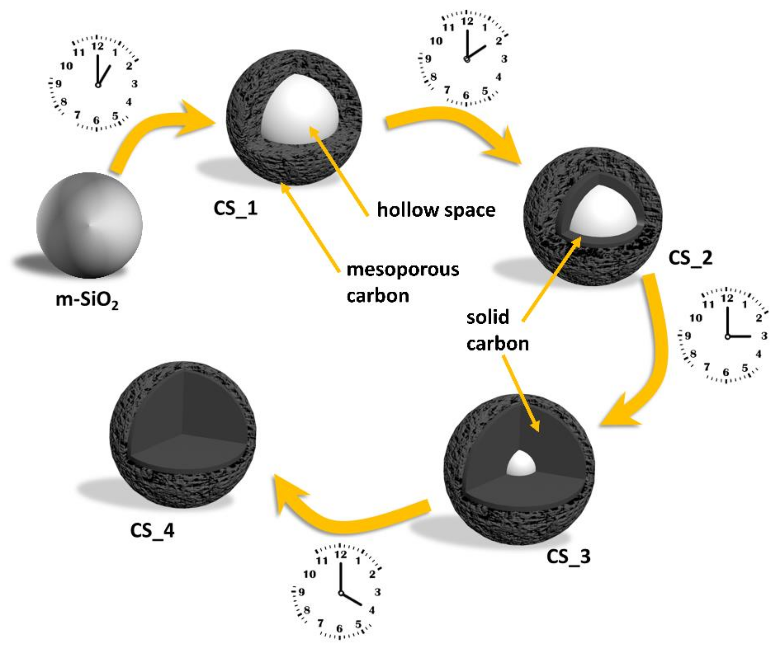
So far, the control of the structure of carbon spheres is related to two main structural characteristics: (i) the shell thickness [30,31] and (ii) the order of the pores in the shell. The proposed carbon sphere can exhibit ordered [13,32] and disordered [33] pores. It is well known that the nanoparticle shape has a crucial role in its applications, such as drug delivery [34], filler for polymeric matrices [35,36], and deacidification [37,38]. In our contribution, solid silica nanoparticles serve as a hard template in CVD-grown carbon spheres. Furthermore, optimizing the process time of the procedure allowed the growth of carbon spheres with empty cores, solid carbon spheres, and intermediate carbon structures. We also propose a mechanism for sphere formation, taking into consideration the mesoporous silica particles (m-SiO2) being utilized as the template. Schematically, the change in morphology of the spheres prepared using CVD for different times, from hollow to solid carbon spheres, is shown in Figure 1.
2. Materials and Methods
2.1. Synthesis of Mesoporous Silica Spheres
Mesoporous silica spheres were prepared as templates for further processing. Briefly, the surfactant, hexadecyltrimethylammonium bromide (CTAB, MERCK, Darmstadt, Germany; 900 mg), was added to a mixture of ethanol (EtOH, MERCK, Darmstadt, Germany; 180 mL), distilled water (240 mL), and ammonia (MERCK, Darmstadt, Germany; 25 wt.%, 3.3 mL), before being sonicated to obtain a homogeneous solution, and stirred vigorously for 30 min. Next, the silica precursor, tetraethyl orthosilicate (TEOS, MERCK, Darmstadt, Germany; 1.2 mL), was added to the reaction mixture and subsequently stirred at room temperature overnight. Finally, the product was centrifuged and dried [39].
2.2. Synthesis of Carbon Spheres with Different Shell Thickness (from Hollow to Solid Carbon Spheres)
The as-prepared m-SiO2 template was used to prepare the carbon spheres using the CVD method. The m-SiO2 template in an alumina boat was placed into a tube furnace in the presence of argon and ethylene at flow rates of 100 sccm and 30 sccm, respectively. The temperature was raised to 800 °C. Processes with different carbonization times (1, 2, 3, and 4 h) were performed. Afterward, the resulting spheres (m-SiO2_CS) were washed with hydrofluoric acid to remove the silica and obtain the final product—carbon spheres with different morphology.
2.3. Characterization
The morphology of the samples was examined with a transmission electron microscope (TEM; Tecnai F30, Thermo Fisher Scientific, Waltham, MA, USA) and a scanning electron microscope (SEM; VEGA3 TESCAN, Brno, Czech Republic; high voltage (HV): 30 kV, working distance (WD): 5.25 mm). X-ray diffraction (XRD) patterns were carried out using an X’Pert Philips Diffractometer (X’Pert PRO Philips diffractometer, Co. Ka radiation, Almelo, Holland) with a Cu lamp (Kα1 = 1.54056 Å) to investigate the crystal composition of the samples. Thermogravimetric analysis (TGA) was carried out on 10-mg samples using a DTA-Q600 SDT TA Instrument (TA Instrument, New Castle, DE, USA) at a heating rate of 5 °C/min from room temperature to 900 °C in air. Raman spectra were determined using an inVia Raman Microscope (Renishaw, New Mills Wotton-under-Edge, UK) with an excitation wavelength of 785 nm. N2 adsorption/desorption isotherms were obtained using a Quadrosorb SI (Quantachrome Instruments, Boynton Beach, FL, USA). Specific surface area was calculated according to the Brunauer–Emmett–Teller (BET) method, and pore size distribution was determined using the density functional theory (DFT) method.
3. Results and Discussion
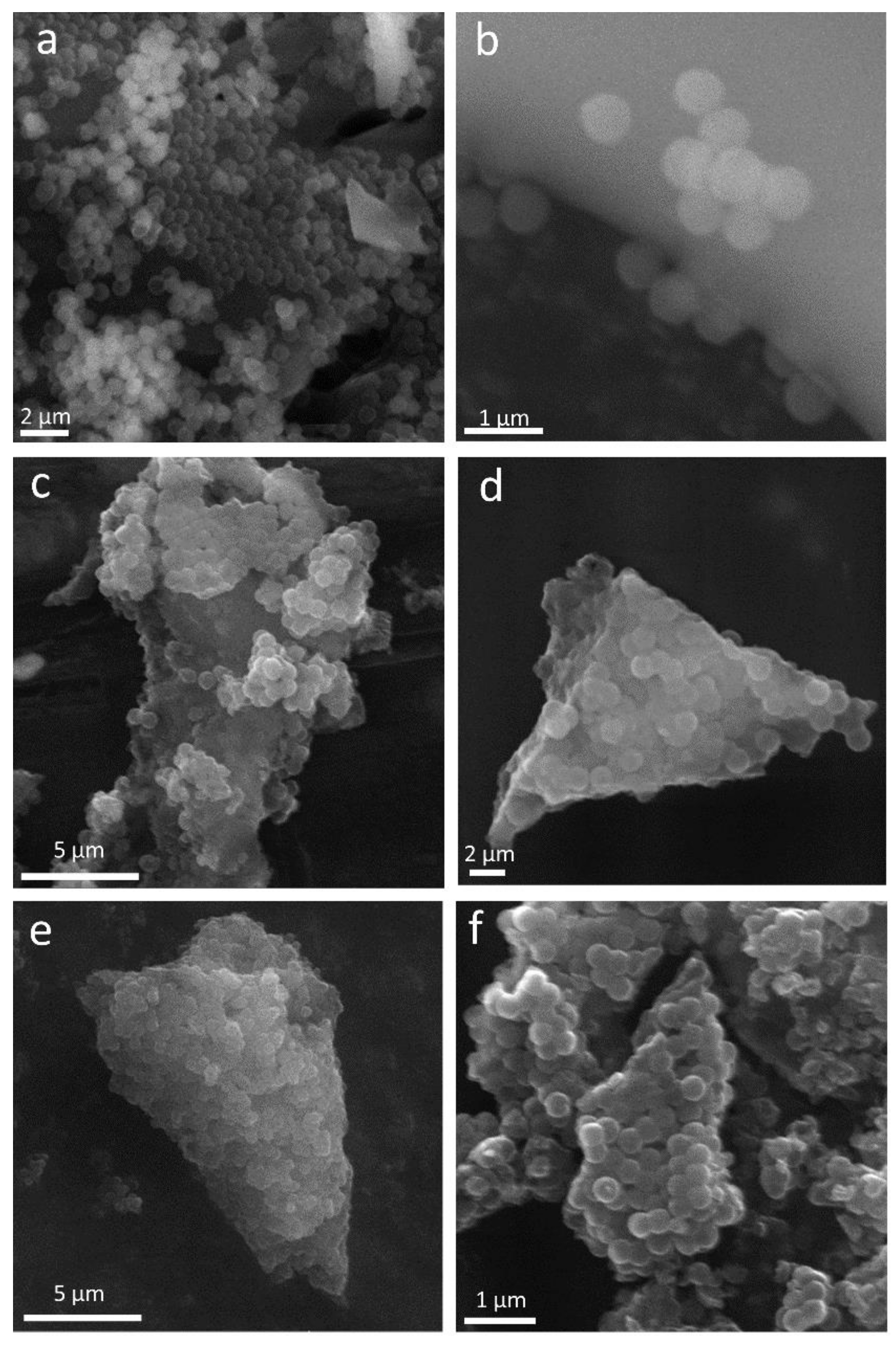
Scanning electron microscopy was used to reveal the evolution of morphology and structure of the obtained materials, i.e., the silica template and all carbon spheres. As illustrated in Figure 2a,b, a uniform and spherical shape with a diameter of ~400 nm, as well as a smooth surface, can clearly be observed in the silica template sample. After the CVD process, carbon materials kept the initial spherical shape of the silica template and exhibited a similar diameter of ~400 nm. It can clearly be observed that, with an increase in synthesis time, the morphology of the carbon spheres did not change significantly (Figure 2c–f).
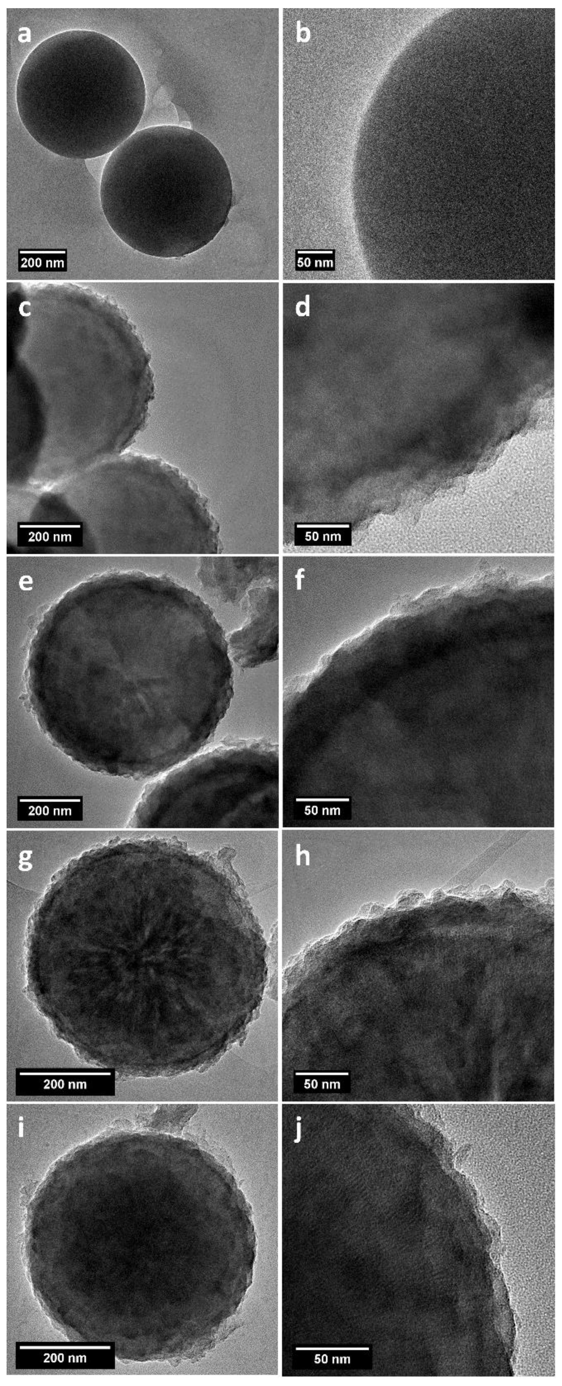
Representative TEM images of silica spheres and carbon spheres are presented in Figure 3. Silica spheres used as a template for the carbon spheres had diameter of ~400 nm (Figure 3a,b), which was confirmed by SEM analysis [34]. The carbon spheres after removal of the silica template had porous shells with thicknesses changing with time. After 1 h (CS_1) of CVD, the shell thickness was ~70 nm (Figure 3c,d). After 2 h (CS_2), the shell diameter decreased to ~30 nm (Figure 3g,h). The spheres produced after 3 h of CVD (CS_3) had a shell thickness ~20 nm (Figure 3i,j). When the process took 4 h, the sample did not exhibit the presence of a shell. Its diameter was the same as the silica template. Moreover, the core of the sphere was no longer hollow. Solid carbon spheres were produced under these experimental conditions. Interestingly, with the increase in process time, the carbon atoms increasingly diffused from the external shell into the spheres.
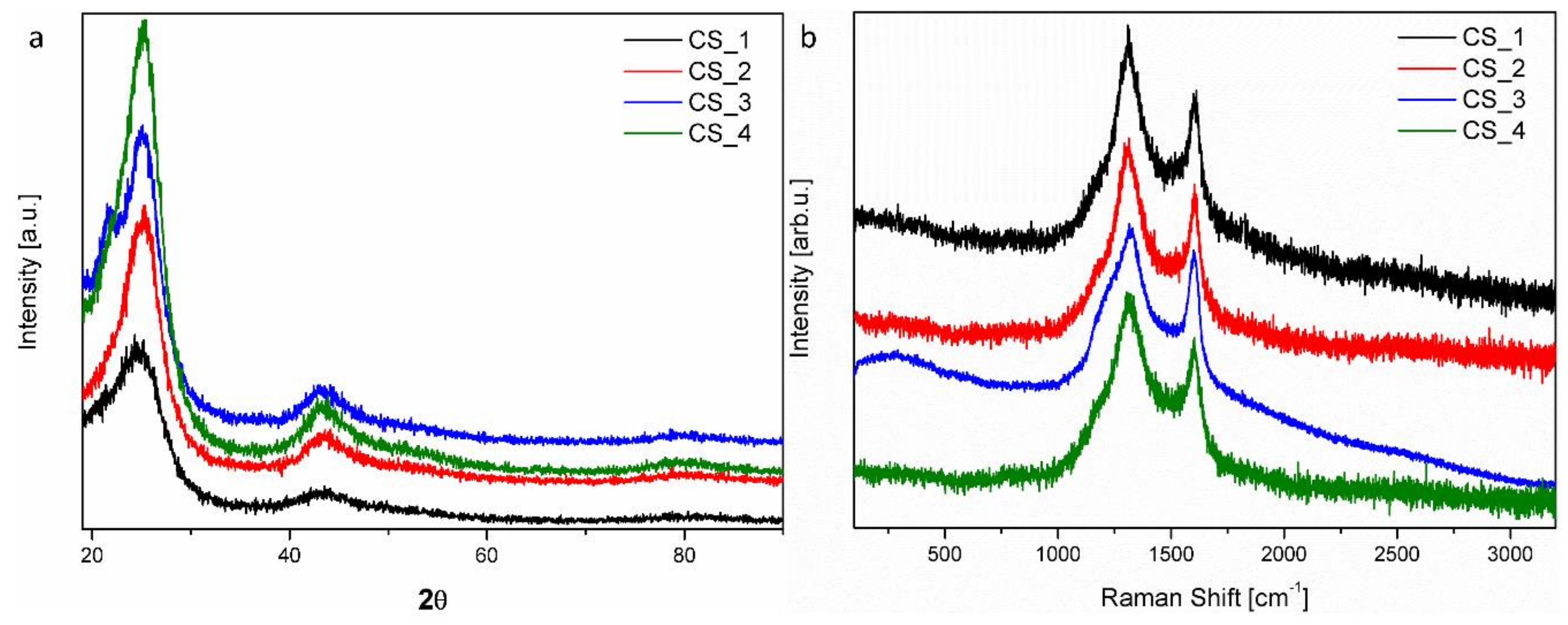
The graphitization degree of the carbon spheres was determined using XRD. Figure 4a displays the XRD patterns, in which the two peaks at ~25° and ~43° can be assigned to typical graphitic (002) and (100) planes, respectively. The broadening of the two peaks suggests a low graphitization degree and the possible presence of amorphous carbon. However, upon extending the CVD process time, sharper peaks with greater intensity were detected. This means that the degree of graphitization of the final material increased.
The bonding, order, and crystallinity of the materials were studied using Raman spectroscopy (Figure 4b). The presence of disordered graphitic materials was suggested by the two Raman modes. The peak at 1604 cm−1 (G band) corresponds to the E2g mode of hexagonal graphite, and it is related to the vibration of the sp2-hybridized carbon atoms in the graphite layer. This implies that the carbon spheres were composed of graphitic carbon, which is consistent with the TEM and XRD results. The D band at approximately 1312 cm−1 is associated with the vibration of carbon atoms with dangling bonds in the plane with termination by disordered graphite. The D band had higher intensity than the G band, which suggests that the obtained carbon spheres had several defects, and they consisted mostly of amorphous carbon [40].
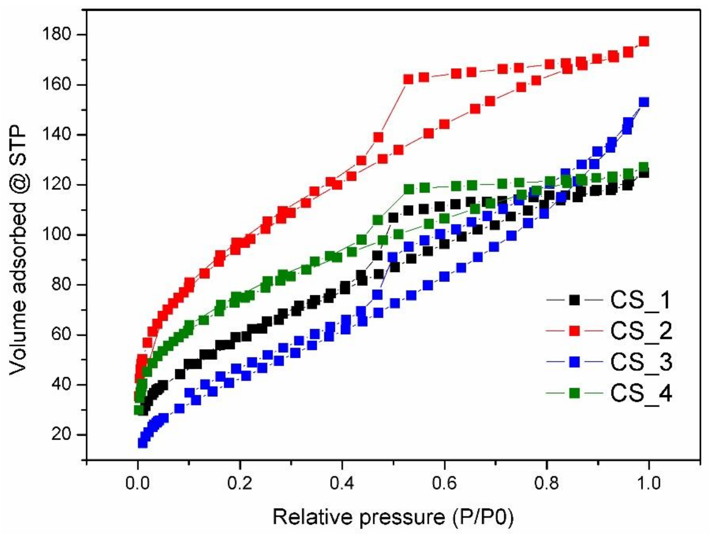
The porosity of the synthesized samples was tested using N2 adsorption/desorption experiments. The textural properties are listed in Table 1. Type IV isotherms with H4 hysteresis loops were observed in all samples, which are typical of mesoporous materials (Figure 5). The position of the P/P0 inflection points is associated with the range of mesopore size, and the slope degree of the steps indicate the uniformity of mesopore size. There were capillary condensation steps at P/P0 of 0.4–1.0, ascribed to mesopores in the samples [41]. The pore size distribution curves show the existence of uniform mesopores below 4 nm. These mesopores should be located in the shell of carbon spheres. Upon increasing the time of synthesis, the BET specific surface area of carbon spheres increased gradually to 344.8 m2·g−1, as well as the total pore volume to 0.248 cm3·g−1, in CS_2. A further increase in the process time caused a decrease in BET specific surface area and total pore volume, which may be related to the blocking of mesoporous channels by the diffused carbon. When the carbon spheres were filled with carbon, the diffusion ceased and the shell disappeared; the BET specific surface area and total pore size distribution were again enhanced. The control of the texture parameters of carbon spheres, such as specific surface area, total pore volume, and pore size, is important in adsorption and catalytic applications.
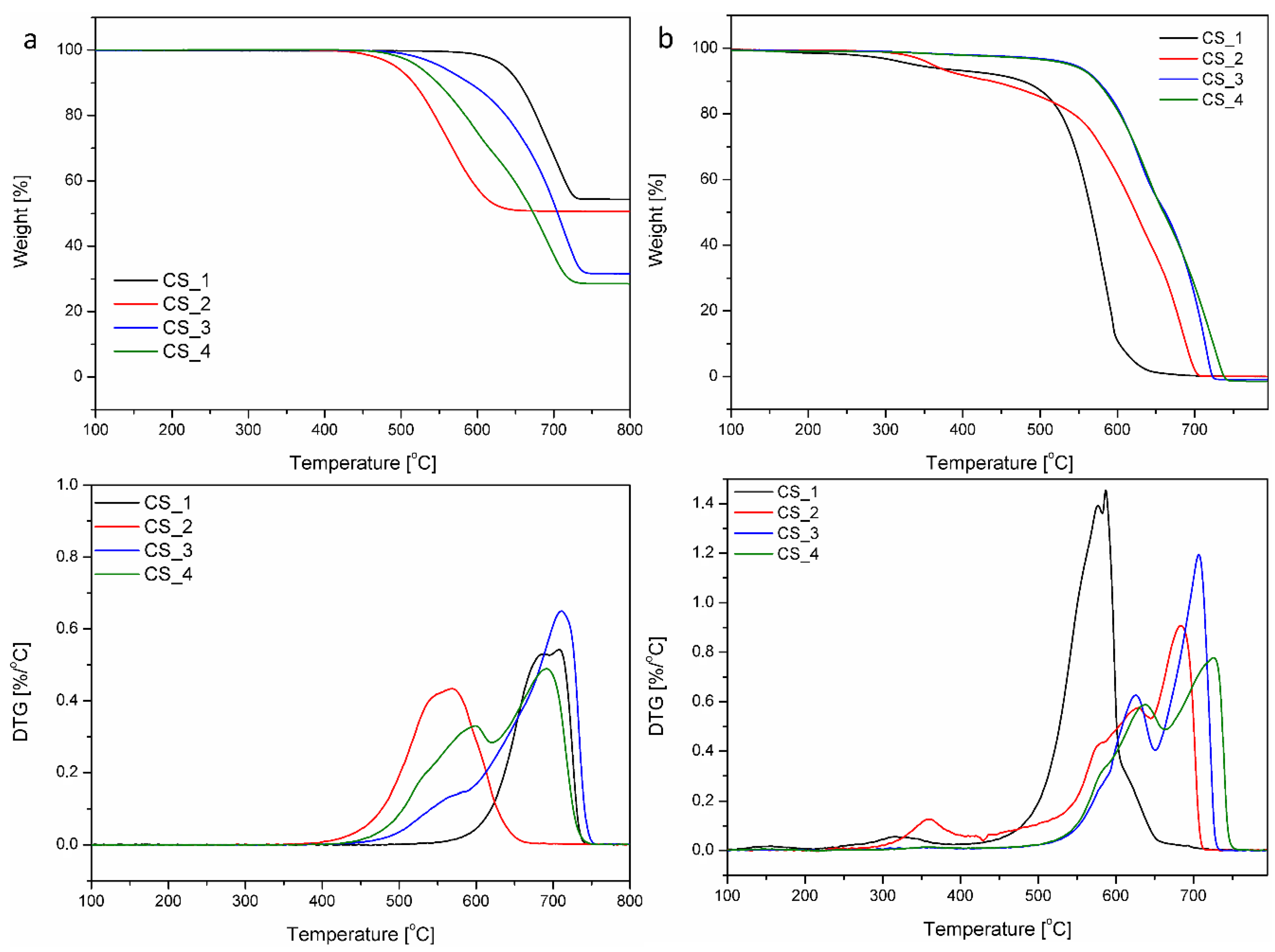
The TGA measurements in Figure 6 provide information on the carbon content and quality of the structure in the carbon spheres. It is known that carbon with a better crystalline structure decomposes at higher temperature. For example, carbon nanomaterial with well-ordered sp2 hybridization starts decomposing above 600 °C [42,43,44], while amorphous carbon initiates its decomposition at a lower temperature, ca. 500 °C and below [45,46]. Figure 6a shows that our carbon spheres were oxidized above 415 °C, which means that our carbon spheres consisted mostly of amorphous carbon, which is in full agreement with the Raman and XRD spectra. As the temperature increased further, weight decreased rapidly until all of carbon spheres were exhausted at approximately 730 °C. The ash contents of the samples after combustion were 54.3% (w/w) for m-SiO2_CS_1, 50.6% for m-SiO2_CS_2, 31.5% for m-SiO2_CS_3, and 28.5% for m-SiO2_CS_4, which indicates that the contribution of silica decreased. A simultaneous increase in synthesis time and the amount of carbon in the samples was observed. After removing the silica core, the TGA curves changed slightly (Figure 6b). All samples consisted only of carbon; thus, they were completely burnt at high temperatures of up to 800 °C, proving the high purity of the final samples. However, the temperature of total combustion was different, and it shifted with the time of the CVD process. CS_1 burned completely at about 650 °C, while CS_4 burned completely at about 755 °C. Full thermal decomposition parameters calculated from the differential thermogravimetry (DTG) curves are listed in Table 2. The start (Tstart) and end (Tend) temperatures of the peak, as well as the temperature at which the peak had its maximum (Tmax), are specified. Both Tmax and Tend shifted to higher temperature values with an increase in CVD process time. This indicates that the carbon crystallinity was enhanced when the CVD process was longer. This is in good agreement with the increasing intensity of the peak at 25° in the XRD measurements shown earlier.
Detailed microscopic analysis allowed a proposal of the growth mechanism. In the initial phase of synthesis, carbon atoms adsorbed onto the surface of SiO2, forming a porous shell. Therefore, the diameter of the spheres after 1 h of CVD process was larger than that of the pristine template. With an increase in CVD time, carbon atoms started diffusing from the external part of the shell to the core, and the shell thickness decreased. However, more carbon atoms were deposited onto the interior of the template. Gradually, the shell disappeared and, at some point, the mesoporous channels of silica were filled with diffused carbon. When the carbon spheres were filled with carbon, the diffusion slowed down and the shell disappeared, resulting in the reduction in BET specific surface area and pore size distribution of the carbon spheres. This effect was clearly observed in the case of CS_4.
4. Conclusions
In this work, we successfully fabricated solid and hollow mesoporous carbon spheres with controllable shell thickness, as well as high specific surface area and pore volume, using the CVD method. Specific surface areas and pore volume distributions of the carbon spheres could be tuned with the CVD process time. Optimizing the process time of the procedure allowed the growth of carbon spheres with empty cores (1 h CVD), solid carbon spheres (4 h CVD), and intermediate carbon structures (2 or 3 h CVD). The mechanism of sphere formation was also proposed. It is believed that this facile synthesis route can be a way of preparing carbon spheres with different morphology (from hollow to solid), which can be tested for various applications, such as energy storage and conversion, adsorption, catalytic, biomedical, and environmental applications.
Author Contributions
Conceptualization, X.C. and E.M.; methodology, X.C. and E.M.; investigation, W.K., K.W. and M.B.; resources, E.M.; writing—original draft preparation, W.K.; writing—review and editing, E.M.; supervision, E.M.; funding acquisition, E.M.
Funding
This research was funded by National Science Centre Poland, grant number UMO-2015/18/E/ST8/00291.
Acknowledgments
The authors are grateful for the financial support from the National Science Centre Poland within the SONATA BIS Project No. UMO-2015/18/E/ST8/00291.
Conflicts of Interest
The authors declare no conflicts of interest.
References
- Wang, Q.; Yan, J.; Wang, Y.; Wei, T.; Zhang, M.; Jing, X.; Fan, Z. Three-dimensional flower-like and hierarchical porous carbon materials as high-rate performance electrodes for supercapacitors. Carbon 2014, 67, 119–127. [Google Scholar] [CrossRef]
- Li, Q.; Jiang, R.; Dou, Y.; Wu, Z.; Huang, T.; Feng, D.; Yang, J.; Yu, A.; Zhao, D. Synthesis of mesoporous carbon spheres with a hierarchical pore structure for the electrochemical double-layer capacitor. Carbon 2011, 49, 1248–1257. [Google Scholar] [CrossRef]
- Wang, Z.L.; Kang, Z.C. Pairing of pentagonal and heptagonal carbon rings in the growth of nanosize carbon spheres synthesized by a mixed-valent oxide-catalytic carbonization process. J. Phys. Chem. 1996, 100, 17725–17731. [Google Scholar] [CrossRef]
- Wang, Z.L.; Kang, Z.C. Graphitic structure and surface chemical activity of nanosize carbon spheres. Carbon 1997, 35, 419–426. [Google Scholar] [CrossRef] [Green Version]
- Sharon, M.; Mukhopadhyay, K.; Yase, K.; Iijima, S.; Ando, Y.; Zhao, X. Spongy carbon nanobeads—A new material. Carbon 1998, 36, 507–511. [Google Scholar] [CrossRef]
- Lou, X.W.; Li, C.M.; Archer, L.A. Designed synthesis of coaxial SnO2@carbon hollow nanospheres for highly reversible lithium storage. Adv. Mater. 2009, 21, 2536–2539. [Google Scholar] [CrossRef]
- Kim, S.; Shibata, E.; Sergiienko, R.; Nakamura, T. Purification and separation of carbon nanocapsules as a magnetic carrier for drug delivery systems. Carbon 2008, 46, 1523–1529. [Google Scholar] [CrossRef]
- Ma, Y.; Hu, Z.; Huo, K.; Lu, Y.; Hu, Y.; Liu, Y.; Hu, J.; Chen, Y. A practical route to the production of carbon nanocages. Carbon 2005, 43, 1667–1672. [Google Scholar] [CrossRef]
- Chen, X.; Kierzek, K.; Cendrowski, K.; Pelech, I.; Zhao, X.; Feng, J.; Kalenczuk, R.J.; Tang, T.; Mijowska, E. CVD generated mesoporous hollow carbon spheres as supercapacitors. Colloids Surf. A 2012, 396, 246–250. [Google Scholar] [CrossRef]
- Lazzara, G.; Cavallaro, G.; Panchal, A.; Fakhrullin, R.; Stavitskaya, A.; Vinokurov, V.; Lvov, Y. An assembly of organic-inorganic composites using halloysite clay nanotubes. Curr. Opin. Colloid Interface Sci. 2018, 35, 42–50. [Google Scholar] [CrossRef]
- Hu, J.; Chen, M.; Fang, X.; Wu, L. Fabrication and application of inorganic hollow spheres. Chem. Soc. Rev. 2011, 40, 5472–5491. [Google Scholar] [CrossRef] [PubMed]
- Yoon, S.B.; Sohn, K.; Kim, J.Y.; Shin, C.-H.; Yu, J.-S.; Hyeon, T. Fabrication of carbon capsules with hollow macroporous core/mesoporous shell structures. Adv. Mater. 2002, 14, 19–21. [Google Scholar] [CrossRef]
- Xia, Y.; Mokaya, R. Ordered mesoporous carbon hollow spheres nanocast using mesoporous silica via chemical vapor deposition. Adv. Mater. 2004, 16, 886–891. [Google Scholar] [CrossRef]
- Liang, C.; Li, Z.; Dai, S. Mesoporous carbon materials: Synthesis and modification. Angew. Chem. Int. Ed. 2008, 47, 3696–3717. [Google Scholar] [CrossRef] [PubMed]
- Lee, D.; Rubner, M.F.; Cohen, R.E. Formation of nanoparticle-loaded microcapsules based on hydrogen-bonded multilayers. Chem. Mater. 2005, 17, 1099–1105. [Google Scholar] [CrossRef]
- Gill, I.; Ballesteros, A. Encapsulation of biologicals within silicate, siloxane, and hybrid sol-gel polymers: An efficient and generic approach. J. Am. Chem. Soc. 1998, 120, 8587–8598. [Google Scholar] [CrossRef]
- Liu, H.J.; Cui, W.J.; Jin, L.H.; Wang, C.X.; Xia, Y.Y. Preparation of three-dimensional ordered mesoporous carbon sphere arrays by a two-step templating route and their application for supercapacitors. J. Mater. Chem. 2009, 19, 3661–3667. [Google Scholar] [CrossRef]
- Huang, X.; Kim, S.; Heo, M.S.; Kim, J.E.; Suh, H.; Kim, I. Easy synthesis of hierarchical carbon spheres with superior capacitive performance in supercapacitors. Langmuir 2013, 29, 12266–12274. [Google Scholar] [CrossRef] [PubMed]
- Wang, J.; Feng, S.; Song, Y.; Li, W.; Gao, W.; Elzatahry, A.A.; Aldhayan, D.; Xia, Y.; Zhao, D. Synthesis of hierarchically porous carbon spheres with yolk-shell structure for high performance supercapacitors. Catal. Today 2015, 243, 199–208. [Google Scholar] [CrossRef]
- Demir Cakan, R.; Titirici, M.-M.; Antonietti, M.; Cui, G.; Maier, J.; Hu, Y.-S. Hydrothermal carbon spheres containing silicon nanoparticles: Synthesis and lithium storage performance. Chem. Commun. 2008, 3759. [Google Scholar] [CrossRef] [PubMed]
- Zhang, W.-M.; Hu, J.-S.; Guo, Y.-G.; Zheng, S.-F.; Zhong, L.-S.; Song, W.-G.; Wan, L.-J. Tin-nanoparticles encapsulated in elastic hollow carbon spheres for high-performance anode material in lithium-Ion batteries. Adv. Mater. 2008, 20, 1160–1165. [Google Scholar] [CrossRef]
- Zheng, G.; Lee, S.W.; Liang, Z.; Lee, H.-W.; Yan, K.; Yao, H.; Wang, H.; Li, W.; Chu, S.; Cui, Y. Interconnected hollow carbon nanospheres for stable lithium metal anodes. Nat. Nanotechnol. 2014, 9, 618–623. [Google Scholar] [CrossRef] [PubMed]
- Wang, L.; Zhang, J.; Yang, S.; Sun, Q.; Zhu, L.; Wu, Q.; Zhang, H.; Meng, X.; Xiao, F.-S. Sulfonated hollow sphere carbon as an efficient catalyst for acetalisation of glycerol. J. Mater. Chem. A 2013, 1, 9422. [Google Scholar] [CrossRef]
- Bian, X.; Zhu, J.; Liao, L.; Scanlon, M.D.; Ge, P.; Ji, C.; Girault, H.H.; Liu, B. Nanocomposite of MoS2 on ordered mesoporous carbon nanospheres: A highly active catalyst for electrochemical hydrogen evolution. Electrochem. Commun. 2012, 22, 128–132. [Google Scholar] [CrossRef]
- Wickramaratne, N.P.; Jaroniec, M. Importance of small micropores in CO2 capture by phenolic resin-based activated carbon spheres. J. Mater. Chem. A 2013, 1, 112–116. [Google Scholar] [CrossRef]
- Wickramaratne, N.P.; Jaroniec, M. Activated carbon spheres for CO2 adsorption. ACS Appl. Mater. Interfaces 2013, 5, 1849–1855. [Google Scholar] [CrossRef] [PubMed]
- Fang, Y.; Zheng, G.; Yang, J.; Tang, H.; Zhang, Y.; Kong, B.; Lv, Y.; Xu, C.; Asiri, A.M.; Zi, J.; et al. Dual-pore mesoporous carbon@silica composite core-shell nanospheres for multidrug delivery. Angew. Chem. Int. Ed. 2014, 53, 5366–5370. [Google Scholar] [CrossRef] [PubMed]
- Chen, Y.; Xu, P.; Wu, M.; Meng, Q.; Chen, H.; Shu, Z.; Wang, J.; Zhang, L.; Li, Y.; Shi, J. Colloidal RBC-shaped, hydrophilic, and hollow mesoporous carbon nanocapsules for highly efficient biomedical engineering. Adv. Mater. 2014, 26, 4294–4301. [Google Scholar] [CrossRef] [PubMed]
- Wang, J.; Hu, Z.; Xu, J.; Zhao, Y. Therapeutic applications of low-toxicity spherical nanocarbon materials. NPG Asia Mater. 2014, 6, e84. [Google Scholar] [CrossRef]
- Fu, J.; Xu, Q.; Chen, J.; Chen, Z.; Huang, X.; Tang, X. Controlled fabrication of uniform hollow core porous shell carbon spheres by the pyrolysis of core/shell polystyrene/cross-linked polyphosphazene composites. Chem. Commun. 2010, 46, 6563–6565. [Google Scholar] [CrossRef] [PubMed]
- Liu, C.; Yin, H.; Wang, A.; Wu, Z.; Wu, G.; Jiang, T.; Shen, Y.; Jiang, T. Size-controlled preparation of hollow silica spheres and glyphosate release. Trans. Nonferrous Met. Soc. China 2012, 22, 1161–1168. [Google Scholar] [CrossRef]
- Yang, S.; Feng, X.; Zhi, L.; Cao, Q.; Maier, J.; Müllen, K. Nanographene-constructed hollow carbon spheres and their favorable electroactivity with respect to lithium storage. Adv. Mater. 2010, 22, 838–842. [Google Scholar] [CrossRef] [PubMed]
- Zielinska, B.; Michalkiewicz, B.; Mijowska, E.; Kalenczuk, R.J. Advances in Pd nanoparticle size decoration of mesoporous carbon spheres for energy application. Nanoscale Res. Lett. 2015, 10, 430. [Google Scholar] [CrossRef] [PubMed]
- Wickström, H.; Hilgert, E.; Nyman, J.; Desai, D.; Şen Karaman, D.; de Beer, T.; Sandler, N.; Rosenholm, J. Inkjet printing of drug-loaded mesoporous silica nanoparticles—A platform for drug development. Molecules 2017, 22, 2020. [Google Scholar] [CrossRef] [PubMed]
- Cavallaro, G.; Lazzara, G.; Milioto, S. Dispersions of nanoclays of different shapes into aqueous and solid biopolymeric matrices. extended physicochemical study. Langmuir 2011, 27, 1158–1167. [Google Scholar] [CrossRef] [PubMed]
- Zhou, S.; Hrymak, A.N.; Kamal, M.R. Effect of hybrid carbon fillers on the electrical and morphological properties of polystyrene nanocomposites in microinjection molding. Nanomaterials 2018, 8, 779–793. [Google Scholar] [CrossRef] [PubMed]
- Cavallaro, G.; Milioto, S.; Parisi, F.; Lazzara, G. Halloysite nanotubes loaded with calcium hydroxide: Alkaline fillers for the deacidification of waterlogged archeological woods. ACS Appl. Mater. Interfaces 2018, 10, 27355–27364. [Google Scholar] [CrossRef] [PubMed]
- De Cicco, D.; Asaee, Z.; Taheri, F. Use of nanoparticles for enhancing the interlaminar properties of fiber-reinforced composites and adhesively bonded joints—A review. Nanomaterials 2017, 7, 360. [Google Scholar] [CrossRef] [PubMed]
- Wilgosz, K.; Chen, X.; Kierzek, K.; Machnikowski, J.; Kalenczuk, R.J.; Mijowska, E. Template method synthesis of mesoporous carbon spheres and its applications as supercapacitors. Nanoscale Res. Lett. 2012, 7, 269. [Google Scholar] [CrossRef] [PubMed]
- Wang, Y.; Alsmeyer, D.C.; Mccreery, R.L. Raman spectroscopy of carbon materials: Structural basis of observed spectra. Carbon 1990, 2, 557–563. [Google Scholar] [CrossRef]
- Wang, J.; Liu, Q. An ordered mesoporous aluminosilicate oxynitride template to prepare N-incorporated ordered mesoporous carbon. J. Phys. Chem. C 2007, 111, 7266–7272. [Google Scholar] [CrossRef]
- Dunens, O.M.; Mackenzie, K.J.; Harris, A.T. Synthesis of multiwalled carbon nanotubes on fly ash derived catalysts. Environ. Sci. Technol. 2009, 43, 7889–7894. [Google Scholar] [CrossRef] [PubMed]
- Ajayan, P.M.; Ebbesen, T.W.; Ichihashi, T.; Iijima, S.; Tanigaki, K.; Hiura, H. Opening carbon nanotubes with oxygen and implications for filling. Nature 1993, 362, 522–525. [Google Scholar] [CrossRef]
- Rinzler, G.; Liu, J.; Dai, H.; Nikolaev, P.; Huffman, C.B.; Rodríguez-Macías, F.J.; Boul, P.J.; Lu, H.; Heymann, D.; Colbert, D.T.; et al. Large-scale purification of single-wall carbon nanotubes: Process, product, and characterization. Appl. Phys. A Mater. Sci. Process. 1998, 67, 29–37. [Google Scholar] [CrossRef]
- Hou, P.; Liu, C.; Tong, Y.; Xu, S.; Liu, M.; Cheng, H. Purification of single-walled carbon nanotubes synthesized by the hydrogen arc-discharge method. J. Mater. Res. 2001, 16, 2526–2529. [Google Scholar] [CrossRef]
- Lima, A.F.; Musumeci, A.; Liu, H.W.; Waclawik, E.; Silva, G. Purity evaluation and influence of carbon nanotubes on carbon nanotube/graphite thermal stability. J. Therm. Anal. Calorim. 2009, 97, 257–263. [Google Scholar] [CrossRef]
Figure 1.
Scheme presenting the change in morphology of resulting carbon spheres after 1 h (CS_1), 2 h (CS_2), 3 h (CS_3) and 4 h (CS_4) of chemical vapor deposition (CVD).
Figure 1.
Scheme presenting the change in morphology of resulting carbon spheres after 1 h (CS_1), 2 h (CS_2), 3 h (CS_3) and 4 h (CS_4) of chemical vapor deposition (CVD).

Figure 2.
SEM images of silica template (a,b) and carbon spheres after 1 h (c), 2 h (d), 3 h (e), and 4 h (f) of synthesis.
Figure 2.
SEM images of silica template (a,b) and carbon spheres after 1 h (c), 2 h (d), 3 h (e), and 4 h (f) of synthesis.

Figure 3.
TEM images of silica template (a,b) and carbon spheres after 1 h (c,d), 2h (e,f), 3 h (g,h), and 4 h (i,j) of synthesis.
Figure 3.
TEM images of silica template (a,b) and carbon spheres after 1 h (c,d), 2h (e,f), 3 h (g,h), and 4 h (i,j) of synthesis.

Figure 4.
X-ray diffraction (XRD) patterns (a) and Raman spectra (b) of carbon spheres with different times of synthesis.
Figure 4.
X-ray diffraction (XRD) patterns (a) and Raman spectra (b) of carbon spheres with different times of synthesis.

Figure 5.
N2 sorption isotherms of carbon spheres with different times of synthesis.

Figure 6.
Thermogravimetry analysis (TGA) and differential thermogravimetry (DTG) curves of carbon spheres with different times of synthesis. Before (a) and after (b) removing silica template.
Figure 6.
Thermogravimetry analysis (TGA) and differential thermogravimetry (DTG) curves of carbon spheres with different times of synthesis. Before (a) and after (b) removing silica template.


Table 1.
Texture parameters of carbon spheres with different times of synthesis. SBET—Brunauer–Emmett–Teller surface area; Vtotal—total pore volume; m-SiO2—mesoporous silica; CS_1–4—carbon spheres with 1–4 h of chemical vapor deposition.
Table 1.
Texture parameters of carbon spheres with different times of synthesis. SBET—Brunauer–Emmett–Teller surface area; Vtotal—total pore volume; m-SiO2—mesoporous silica; CS_1–4—carbon spheres with 1–4 h of chemical vapor deposition.
| Sample | SBET a (m2·g−1) | Vtotal b (cm3·g−1) | Pore Size c (nm) | Error d |
|---|---|---|---|---|
| m-SiO2 | 224.2 | 0.210 | 2.313 | 0.391% |
| CS_1 | 218.2 | 0.174 | 3.969 | 0.609% |
| CS_2 | 344.8 | 0.248 | 3.167 | 0.970% |
| CS_3 | 169.8 | 0.212 | 2.245 | 0.544% |
| CS_4 | 263.5 | 0.177 | 1.178 | 0.621% |
a Determined using the multipoint BET method. b Calculated from density functional theory (DFT) method for cumulative pore volume. c Determined by the DFT pore diameter mode. d Fitting error from the DFT method summary.
Table 2.
Thermal decomposition parameters of carbon spheres with different times of synthesis from differential thermogravimetry (DTG) curves in Figure 6b.
Table 2.
Thermal decomposition parameters of carbon spheres with different times of synthesis from differential thermogravimetry (DTG) curves in Figure 6b.
| Sample | Tstart (°C) | Tmax (°C) | Tend (°C) |
|---|---|---|---|
| CS_1 | 110 | 580 | 650 |
| CS_2 | 220 | 680 | 715 |
| CS_3 | 450 | 705 | 735 |
| CS_4 | 450 | 725 | 755 |
© 2018 by the authors. Licensee MDPI, Basel, Switzerland. This article is an open access article distributed under the terms and conditions of the Creative Commons Attribution (CC BY) license (http://creativecommons.org/licenses/by/4.0/).
Share and Cite
MDPI and ACS Style
Kukułka, W.; Wenelska, K.; Baca, M.; Chen, X.; Mijowska, E. From Hollow to Solid Carbon Spheres: Time-Dependent Facile Synthesis. Nanomaterials 2018, 8, 861. https://doi.org/10.3390/nano8100861
AMA Style
Kukułka W, Wenelska K, Baca M, Chen X, Mijowska E. From Hollow to Solid Carbon Spheres: Time-Dependent Facile Synthesis. Nanomaterials. 2018; 8(10):861. https://doi.org/10.3390/nano8100861
Chicago/Turabian StyleKukułka, Wojciech, Karolina Wenelska, Martyna Baca, Xuecheng Chen, and Ewa Mijowska. 2018. "From Hollow to Solid Carbon Spheres: Time-Dependent Facile Synthesis" Nanomaterials 8, no. 10: 861. https://doi.org/10.3390/nano8100861
Note that from the first issue of 2016, this journal uses article numbers instead of page numbers. See further details here.