
Fabrication and Water Treatment Application of Carbon Nanotubes (CNTs)-Based Composite Membranes: A Review

Abstract
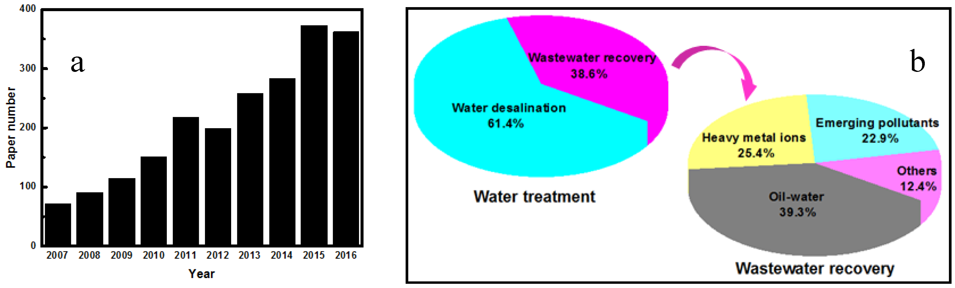
:1. Introduction
2. Fabrication, Growth and Characterization of CNTs
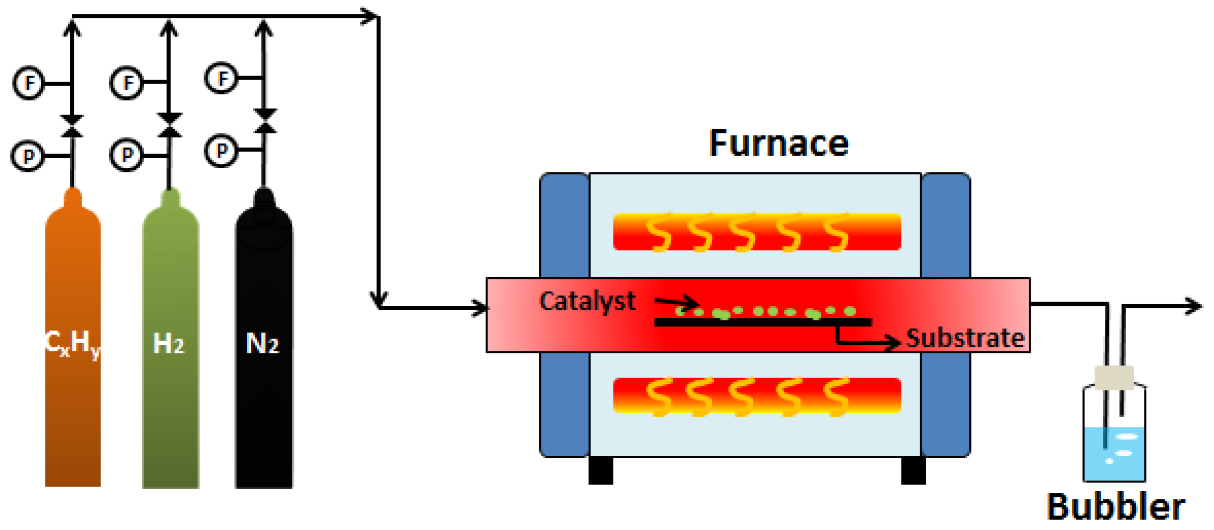
2.1. Fabrication Methods
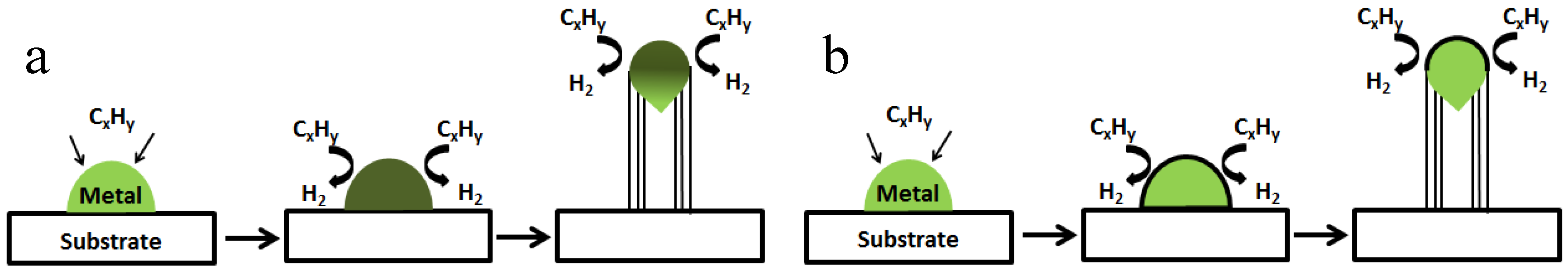
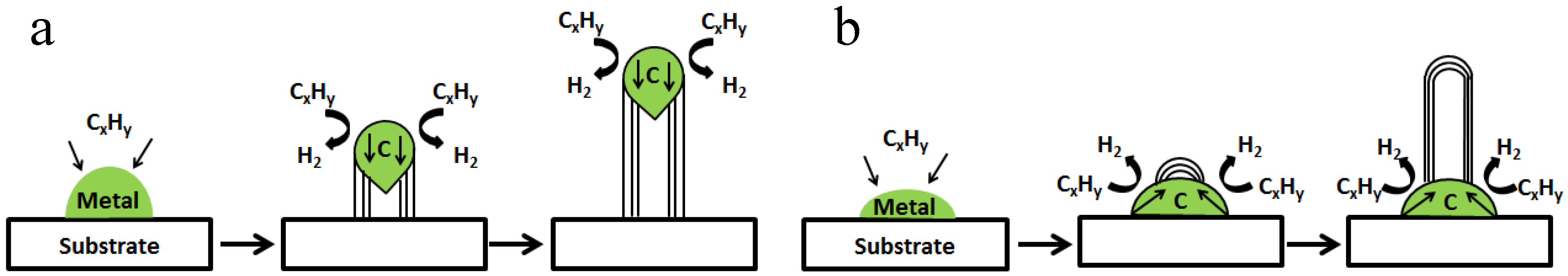
2.2. Growth Mechanisms
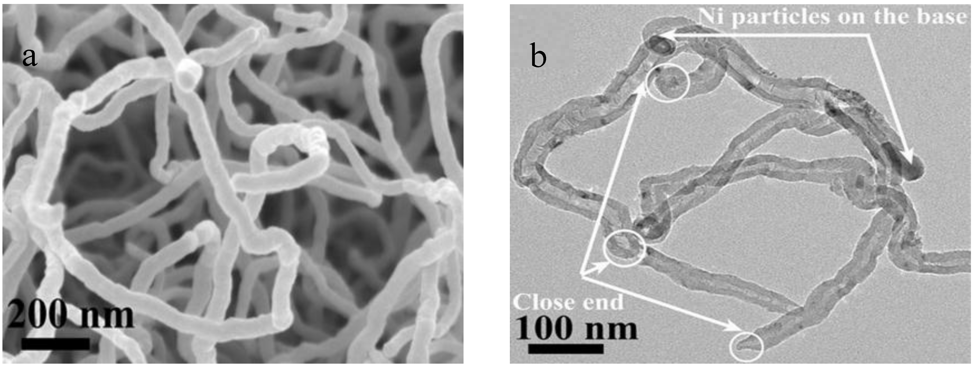
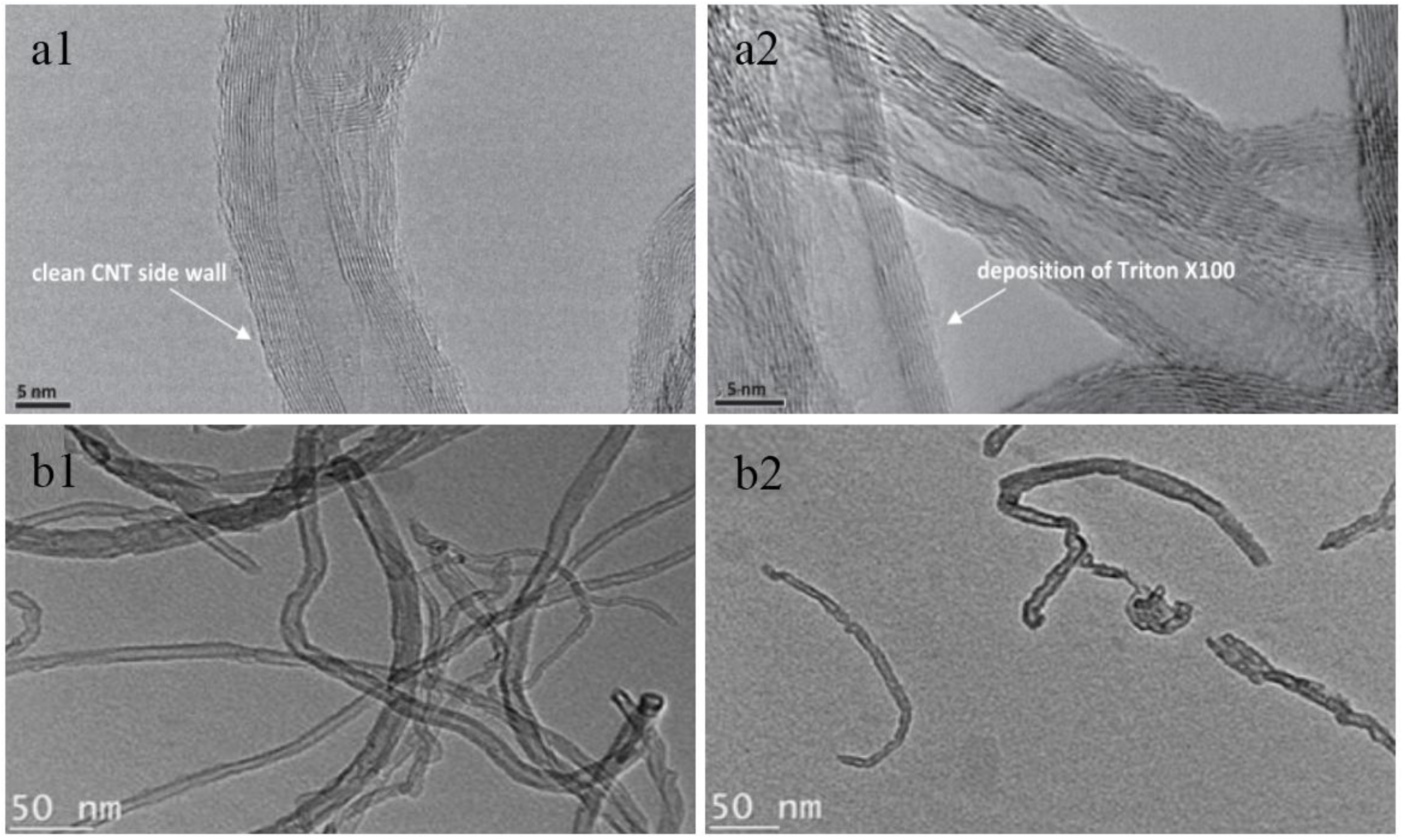
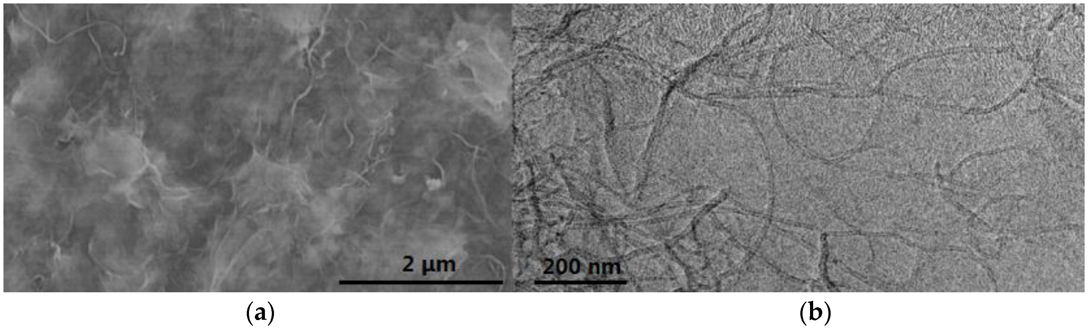
2.3. CNTs Characterizations
3. Fabrication Methods of CNTs-Based Composite Membranes
3.1. Functionalization of CNTs
3.2. Fabrication Methods
3.2.1. CVD Method
3.2.2. Blending Method
3.2.3. In Situ Polymerization Method
3.2.4. Layer-by-Layer Self-Assembly Method
3.2.5. Direct Coating Method
4. Water Treatment Applications
4.1. Water Desalination
4.2. Oil-Water Separation
4.3. Heavy Metal Ions Removal from Wastewater
4.4. Removal of Emerging Pollutants from Wastewater
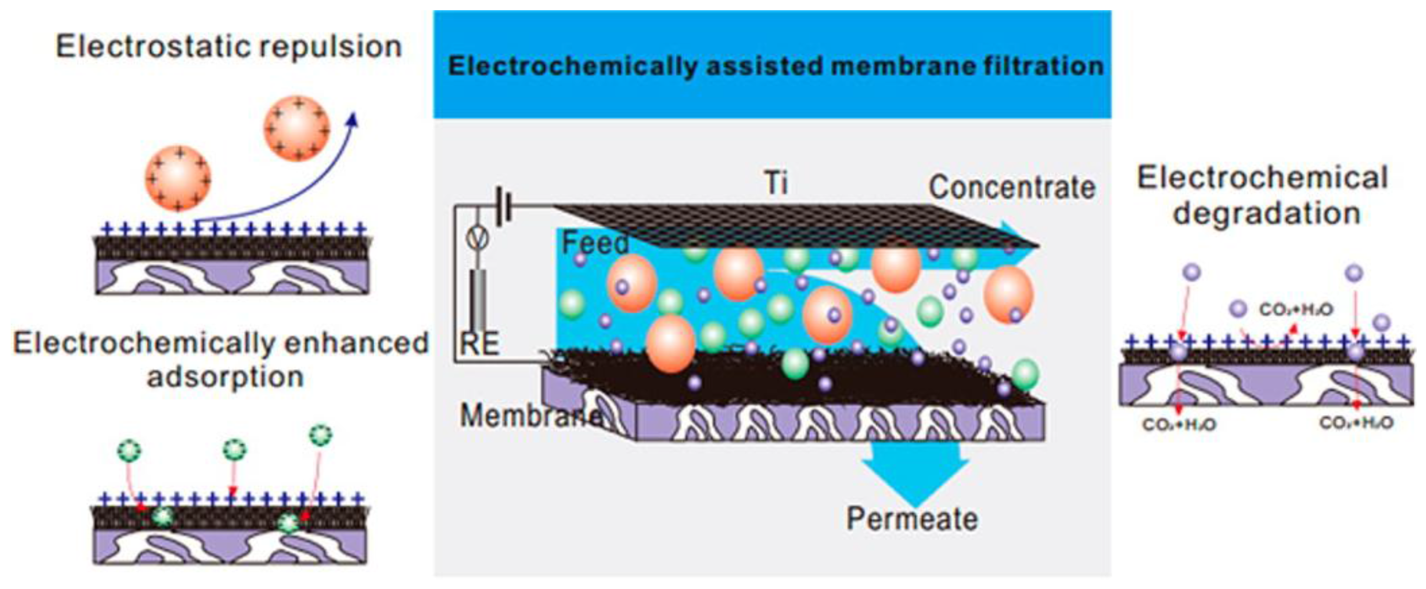
4.5. Membrane Separation Coupled with Assistant Techniques
5. Summary
Acknowledgments
Author Contributions
Conflict of Interest
References
- Elimelech, M.; Phillip, W.A. The future of seawater desalination: energy, technology, and the environment. Science 2011, 333, 712–717. [Google Scholar] [CrossRef] [PubMed]
- Shannon, M.A.; Bohn, P.W.; Elimelech, M.; Georgiadis, J.G.; Marinas, B.J.; Mayes, A.M. Science and technology for water purification in the coming decades. Nature 2008, 452, 301–310. [Google Scholar] [CrossRef] [PubMed]
- Zhou, D.; Zhu, L.; Fu, Y.; Zhu, M.; Xue, L. Development of lower cost seawater desalination processes using nanofiltration technologies—A review. Desalination 2015, 376, 109–116. [Google Scholar] [CrossRef]
- Bruggen, B.V. Integrated membrane separation processes for recycling of valuable wastewater streams: nanofiltration, membrane distillation, and membrane crystallizers revisited. Ind. Eng. Chem. Res. 2013, 52, 10335–10341. [Google Scholar] [CrossRef]
- Tong, T.; Elimelech, M. The global rise of zero liquid discharge for wastewater management: drivers, technologies, and future directions. Environ. Sci. Technol. 2016, 50, 6846–6855. [Google Scholar] [CrossRef] [PubMed]
- Wang, K.; Abdalla, A.A.; Khaleel, M.A.; Hilal, N.; Khraisheh, M.K. Mechanical properties of water desalination and wastewater treatment membranes. Desalination 2017, 401, 190–205. [Google Scholar] [CrossRef]
- Nicolaisen, B. Developments in membrane technology for water treatment. Desalination 2002, 153, 355–360. [Google Scholar] [CrossRef]
- Li, L.; Chen, M.; Dong, Y.; Dong, X.; Cerneaux, S.; Hampshire, S.; Cao, J.; Zhu, L.; Zhu, Z.; Liu, J. A low-cost alumina-mullite composite hollow fiber ceramic membrane fabricated via phase-inversion and sintering method. J. Eur. Ceram. Soc. 2016, 36, 2057–2066. [Google Scholar] [CrossRef]
- Zhu, Z.; Xiao, J.; He, W.; Wang, T.; Wei, Z.; Dong, Y. A phase-inversion casting process for preparation of tubular porous alumina ceramic membranes. J. Eur. Ceram. Soc. 2015, 35, 3187–3194. [Google Scholar] [CrossRef]
- Ismail, A.F.; Goh, P.S.; Sanip, S.M.; Aziz, M. Transport and separation properties of carbon nanotube-mixed matrix membrane. Sep. Purif. Technol. 2009, 70, 12–26. [Google Scholar] [CrossRef]
- Pendergast, M.T.M.; Hoek, E.M.V. A review of water treatment membrane nanotechnologies. Energy Environ. Sci. 2011, 4, 1946–1971. [Google Scholar] [CrossRef]
- Volder, M.F.L.D.; Tawfick, S.H.; Baughman, R.H.; Hart, A.J. Carbon nanotubes: Present and future commercial applications. Science 2013, 339, 535–539. [Google Scholar] [CrossRef] [PubMed]
- Kim, J.; Bruggen, B.V. The use of nanoparticles in polymeric and ceramic membrane structures: Review of manufacturing procedures and performance improvement for water treatment. Environ. Pollut. 2010, 158, 2335–2349. [Google Scholar] [CrossRef] [PubMed]
- Das, R.; Ali, M.E.; Hamid, S.B.A.; Ramakrishna, S.; Chowdhury, Z.Z. Carbon nanotube membranes for water purification: A bright future in water desalination. Desalination 2014, 336, 97–109. [Google Scholar] [CrossRef]
- Goh, P.S.; Ismail, A.F.; Ng, B.C. Carbon nanotubes for desalination: Performance evaluation and current hurdles. Desalination 2013, 308, 2–14. [Google Scholar] [CrossRef]
- Goh, K.; Karahan, H.E.; Wei, L.; Bae, T.-H.; Fane, A.G.; Wang, R.; Chen, Y. Carbon nanomaterials for advancing separation membranes: A strategic perspective. Carbon 2016, 109, 694–710. [Google Scholar] [CrossRef]
- Lee, K.-J.; Park, H.-D. Effect of transmembrane pressure, linear velocity, and temperature on permeate water flux of high-density vertically aligned carbon nanotube membranes. Desalin. Water Treat. 2016, 57, 26706–26717. [Google Scholar] [CrossRef]
- Razali, M.; Kim, J.F.; Attfield, M.; Budd, P.M.; Drioli, E.; Lee, Y.M.; Szekely, G. Sustainable wastewater treatment and recycling in membrane manufacturing. Green Chem. 2015, 17, 5196–5205. [Google Scholar] [CrossRef]
- Ahn, C.H.; Baek, Y.; Lee, C.; Kim, S.O.; Kim, S.; Lee, S.; Kim, S.-H.; Bae, S.S.; Park, J.; Yoon, J. Carbon nanotube-based membranes: Fabrication and application to desalination. J. Ind. Eng. Chem. 2012, 18, 1551–1559. [Google Scholar] [CrossRef]
- Kumar, M.; Ando, Y. Chemical vapor deposition of carbon nanotubes: A review on growth mechanism and mass production. J. Nanosci. Nanotechnol. 2010, 10, 3739–3758. [Google Scholar] [CrossRef] [PubMed]
- Zhao, N.; He, C.; Jiang, Z.; Li, J.; Li, Y. Fabrication and growth mechanism of carbon nanotubes by catalytic chemical vapor deposition. Mater. Lett. 2006, 60, 159–163. [Google Scholar] [CrossRef]
- Mubarak, N.M.; Abdullah, E.C.; Jayakumar, N.S.; Sahu, J.N. An overview on methods for the production of carbon nanotubes. J. Ind. Eng. Chem. 2014, 20, 1186–1197. [Google Scholar] [CrossRef]
- Kukovitsky, E.F.; L’Vov, S.G.; Sainov, N.A. VLS-growth of carbon nanotubes from the vapor. Chem. Phys. Lett. 2000, 317, 65–70. [Google Scholar] [CrossRef]
- Tessonnier, J.P.; Su, D.S. Recent progress on the growth mechanism of carbon nanotubes: A review. Chemsuschem 2011, 4, 824–847. [Google Scholar] [CrossRef] [PubMed]
- Lo, A.Y.; Liu, S.B.; Kuo, C.T. Effect of temperature gradient direction in the catalyst nanoparticle on CNTs growth mode. Nanoscale Res. Lett. 2010, 5, 1393–1402. [Google Scholar] [CrossRef] [PubMed]
- Kim, S.M.; Jeong, S.; Kim, H.C. Investigation of carbon nanotube growth termination mechanism by in situ transmission electron microscopy approaches. Carbon Lett. 2013, 14, 228–233. [Google Scholar] [CrossRef]
- Xiong, J.; Dong, X.; Dong, Y.; Hao, X.; Hampshire, S. Dual-production of nickel foam supported carbon nanotubes and hydrogen by methane catalytic decomposition. Int. J. Hydrogen Energy 2012, 37, 12307–12316. [Google Scholar] [CrossRef]
- Xiong, J.; Dong, X.; Song, Y.; Dong, Y. A high performance Ru-ZrO2/carbon nanotubes-Ni foam composite catalyst for selective CO methanation. J. Power Sources 2013, 242, 132–136. [Google Scholar] [CrossRef]
- Amelinckx, S.; Zhang, X.B.; Bernaerts, D.; Zhang, X.F.; Ivanov, V.; Nagy, J.B.A. Formation Mechanism for Catalytically Grown Helix-Shaped Graphite Nanotubes. Science 1994, 265, 635–639. [Google Scholar] [CrossRef] [PubMed]
- Herrero-Latorre, C.; Alvarez-Méndez, J.; Barciela-García, J.; García-Martín, S.; Peña-Crecente, R.M. Characterization of carbon nanotubes and analytical methods for their determination in environmental and biological samples: A review. Anal. Chim. Acta 2015, 853, 77–94. [Google Scholar] [CrossRef] [PubMed]
- Belin, T.; Epron, F. Characterization methods of carbon nanotubes: a review. Mater. Sci. Eng. B 2005, 119, 105–118. [Google Scholar] [CrossRef]
- Ping, D.; Wang, C.; Dong, X.; Dong, Y. Co-production of hydrogen and carbon nanotubes on nickel foam via methane catalytic decomposition. Appl. Surf. Sci. 2016, 369, 299–307. [Google Scholar] [CrossRef]
- Dresselhaus, M.S.; Dresselhaus, G.; Jorio, A. Raman spectroscopy of carbon nanotubes in 1997 and 2007. J. Phys. Chem. C 2007, 111, 17887–17893. [Google Scholar] [CrossRef]
- Saito, R.; Hofmann, M.; Dresselhaus, G.; Jorio, A.; Dresselhaus, M.S. Raman spectroscopy of graphene and carbon nanotubes. Adv. Phys. 2011, 60, 413–550. [Google Scholar] [CrossRef]
- Dresselhaus, M.S.; Jorio, A.; Saito, R. Characterizing grapheme graphite, and carbon nanotubes by Raman spectroscopy. Annu. Rev. Condens. Matter. Phys. 2010, 1, 89–108. [Google Scholar] [CrossRef]
- Shulga, Y.M.; Tien, T.C.; Huang, C.C.; Lo, S.C.; Muradyan, V.E.; Polyakova, N.V.; Ling, Y.C.; Loutfy, R.O.; Moravsky, A.P. XPS study of fluorinated carbon multi-walled nanotubes. J. Electron. Spectrosc. Rel. Phen. 2007, 160, 22–28. [Google Scholar] [CrossRef]
- Lehman, J.H.; Terrones, M.; Mansfield, E.; Hurst, K.E.; Meunier, V. Evaluating the characteristics of multiwall carbon nanotubes. Carbon 2011, 49, 2581–2602. [Google Scholar] [CrossRef]
- Weisman, R.B. Fluorimetric characterization of single-walled carbon nanotubes. Anal. Bioanal. Chem. 2010, 396, 1015–1023. [Google Scholar] [CrossRef] [PubMed]
- Tofighy, M.A.; Mohammadi, T. Adsorption of divalent heavy metal ions from water using carbon nanotube sheets. J. Hazard. Mater. 2011, 185, 140–147. [Google Scholar] [CrossRef] [PubMed]
- Goh, P.S.; Ng, B.C.; Lau, W.J.; Ismail, A.F. Inorganic nanomaterials in polymeric ultrafiltration membranes for water treatment. Sep. Purif. Rev. 2015, 44, 216–249. [Google Scholar] [CrossRef]
- Hirsch, A. Functionalization of single-walled carbon nanotubes. Angew. Chem. Int. Edit. 2002, 41, 1853–1859. [Google Scholar] [CrossRef]
- Wepasnick, K.A.; Smith, B.A.; Schrote, K.E.; Wilson, H.K.; Diegelmann, S.R.; Fairbrother, D.H. Surface and structural characterization of multi-walled carbon nanotubes following different oxidative treatments. Carbon 2011, 49, 24–36. [Google Scholar] [CrossRef]
- Rosca, I.D.; Watari, F.; Uo, M.; Akasaka, T. Oxidation of multiwalled carbon nanotubes by nitric acid. Carbon 2005, 43, 3124–3131. [Google Scholar] [CrossRef]
- Datsyuk, V.; Kalyva, M.; Papagelis, K.; Parthenios, J.; Tasis, D.; Siokou, A.; Kallitsisa, I.; Galiotis, C. Chemical oxidation of multiwalled carbon nanotubes. Carbon 2008, 46, 833–840. [Google Scholar] [CrossRef]
- Goh, P.S.; Ng, B.C.; Ismail, A.F.; Aziz, M.; Hayashi, Y. Pre-treatment of multi-walled carbon nanotubes for polyetherimide mixed matrix hollow fiber membranes. J. Colloid Interface Sci. 2012, 386, 80–87. [Google Scholar] [CrossRef] [PubMed]
- Celic, E.; Liu, L.; Choi, H. Protein fouling behavior of carbon nanotube/polyethersulfone composite membranes during water filtration. Water Res. 2011, 45, 5287–5294. [Google Scholar] [CrossRef] [PubMed]
- Tofighy, M.A.; Mohammadi, T. Nickel ions removal from water by two different morphologies of induced CNTs in mullite pore channels as adsorptive membrane. Ceram. Int. 2015, 41, 5464–5472. [Google Scholar] [CrossRef]
- Alsawat, M.; Altalhi, T.; Kumeria, T.; Santosa, A.; Losic, D. Carbon nanotube-nanoporous anodic alumina composite membranes with controllable inner diameters and surface chemistry: Influence on molecular transport and chemical selectivity. Carbon 2015, 93, 681–692. [Google Scholar] [CrossRef]
- Tiraferri, A.; Vecitis, C.D.; Elimelech, M. Covalent binding of single-walled carbon nanotubes to polyamide membranes for antimicrobial surface properties. ACS Appl. Mater. Inter. 2011, 3, 2869–2877. [Google Scholar] [CrossRef] [PubMed]
- Peng, F.B.; Pan, F.S.; Sun, H.L.; Lu, L.; Jiang, Z. Novel nanocomposite pervaporation membranes composed of poly(vinyl alcohol) and chitosan-wrapped carbon nanotube. J. Membr. Sci. 2007, 300, 13–19. [Google Scholar] [CrossRef]
- Mi, W.; Lin, J.Y.S.; Li, Y.; Zhang, B. Synthesis of vertically aligned carbon nanotube films on macroporous alumina substrates. Micropor. Mesopor. Mater. 2005, 81, 185–189. [Google Scholar] [CrossRef]
- Mi, W.; Lin, Y.S.; Li, Y. Vertically aligned carbon nanotube membranes on macroporous alumina supports. J. Membr. Sci. 2007, 304, 1–7. [Google Scholar] [CrossRef]
- Tofighy, M.A.; Shirazi, Y.; Mohammadi, T.; Pak, A. Salty water desalination using carbon nanotubes membrane. Chem. Eng. J. 2011, 168, 1064–1072. [Google Scholar] [CrossRef]
- Zhao, Y.; Zhong, Z.; Lowb, Z.-X.; Yao, Z. A multifunctional multi-walled carbon nanotubes/ceramic membrane composite filter for air purification. RSC Adv. 2015, 5, 91951–91959. [Google Scholar] [CrossRef]
- Tofighy, M.A.; Mohammadi, T. Synthesis and characterization of ceramic/carbon nanotubes composite adsorptive membrane for copper ion removal from water. Korean J. Chem. Eng. 2015, 32, 292–298. [Google Scholar] [CrossRef]
- Chen, X.; Hong, L.; Xu, Y.; Ong, Z.W. Ceramic pore channels with inducted carbon nanotubes for removing oil from water. ACS Appl. Mater. Interfaces 2012, 4, 1909–1918. [Google Scholar] [CrossRef] [PubMed]
- Tripathi, N.; Mishra, P.; Joshi, B.; Harsh; Islam, S.S. Catalyst free, excellent quality and narrow diameter of CNT growth on Al2O3 by a thermal CVD technique. Physica E 2014, 62, 43–47. [Google Scholar] [CrossRef]
- Lee, B.; Baek, Y.; Lee, M.; Jeong, D.H.; Lee, H.H.; Yoon, J.; Kim, Y.H. A carbon nanotube wall membrane for water treatment. Nat. Commun. 2015, 6, 7109–7115. [Google Scholar] [CrossRef] [PubMed]
- Vermisoglou, E.C.; Pilatos, G.; Romanos, G.E.; Karanikolos, G.N.; Boukos, N.; Mertis, K.; Kakizis, N.; Kanellopoulos, N.K. Synthesis and characterisation of carbon nanotube modified anodised alumina membranes. Micropor. Mesopor. Mater. 2008, 10, 25–36. [Google Scholar] [CrossRef]
- Yu, K.; Luo, T.; Zhang, Y.; Yang, C.; Shang, L.; Li, C.; Li, Q. Carbon nanotube synthesis over glow discharge-treated Ni/AAO membrane. Mater. Lett. 2009, 63, 566–568. [Google Scholar] [CrossRef]
- Pilatos, B.G.; Vermisoglou, E.C.; Romanos, G.E.; Karanikolos, G.N.; Boukos, N.; Likodimos, V.; Kanellopoulos, N.K. A closer look inside nanotubes: Pore structure evaluation of anodized alumina templated carbon nanotube membranes through adsorption and permeability studies. Adv. Funct. Mater. 2010, 20, 2500–2510. [Google Scholar] [CrossRef]
- Rana, K.; Kucukayan-Dogu, G.; Bengu, E. Growth of vertically aligned carbon nanotubes over self-ordered nano-porous alumina films and their surface properties. Appl. Surf. Sci. 2012, 258, 7112–7117. [Google Scholar] [CrossRef]
- Sarno, M.; Tamburrano, A.; Arurault, L.; Fontorbes, S.; Pantani, R.; Datas, L.; Ciambelli, P.; Sarto, M.S. Electrical conductivity of carbon nanotubes grown inside a mesoporous anodic aluminium oxide membrane. Carbon 2013, 55, 10–22. [Google Scholar] [CrossRef]
- Ke, N.J.; Downard, A.J.; Golovko, V.B. Carbon nanotube diameter control via catalytic Co nanoparticles electrodeposited in porous alumina membranes. RSC Adv. 2015, 5, 25747–25754. [Google Scholar] [CrossRef]
- Gethard, K.; Sae-Khow, O.; Mitra, S. Water desalination using carbon-nanotube-enhanced membrane distillation. ACS Appl. Mater. Interfaces 2011, 3, 110–114. [Google Scholar] [CrossRef] [PubMed]
- Silva, T.L.S.; Morales-Torres, S.; Figueiredo, J.L.; Silva, A.M.T. Multi-walled carbon nanotube/PVDF blended membranes with sponge- and finger-like pores for direct contact membrane distillation. Desalination 2015, 357, 233–245. [Google Scholar] [CrossRef]
- Rahimpour, A.; Jahanshahi, M.; Khalili, S.; Mollahosseini, A.; Zirepour, A.; Rajaeian, B. Novel functionalized carbon nanotubes for improving the surface properties and performance of polyethersulfone (PES) membrane. Desalination 2012, 286, 99–107. [Google Scholar] [CrossRef]
- Ghaemi, N.; Madaeni, S.S.; Daraei, P.; Rajabi, H.; Shojaeimehr, T.; Rahimpour, F.; Shirvani, B. PES mixed matrix nanofiltration membrane embedded with polymer wrapped MWCNT: Fabrication and performance optimization in dye removal by RSM. J. Hazard. Mater. 2015, 298, 111–121. [Google Scholar] [CrossRef] [PubMed]
- Lannoy, C.-F.; Soyer, E.; Wiesner, M.R. Optimizing carbon nanotube-reinforced polysulfone ultrafiltration membranes through carboxylic acid functionalization. J. Membr. Sci. 2013, 447, 395–402. [Google Scholar] [CrossRef]
- Yin, J.; Zhu, G.; Deng, B. Multi-walled carbon nanotubes (MWNTs)/polysulfone (PSU) mixed matrix hollow fiber membranes for enhanced water treatment. J. Membr. Sci. 2013, 437, 237–248. [Google Scholar] [CrossRef]
- Dudchenko, A.V.; Rolf, J.; Russell, K.; Duan, W.; Jassby, D. Organic fouling inhibition on electrically conducting carbon nanotube–polyvinyl alcohol composite ultrafiltration membranes. J. Membr. Sci. 2014, 468, 1–10. [Google Scholar] [CrossRef]
- Majeed, S.; Fierro, D.; Buhr, K.; Wind, J.; Du, B.; Boschetti-de-Fierro, A.; Abetz, V. Multi-walled carbon nanotubes (MWCNTs) mixed polyacrylonitrile (PAN) ultrafiltration membranes. J. Membr. Sci. 2012, 403–404, 101–109. [Google Scholar] [CrossRef]
- Yang, Y.; Nie, C.; Deng, Y.; Cheng, C.; He, C.; Ma, L.; Zhao, C. Improved antifouling and antimicrobial efficiency of ultrafiltration membranes with functional carbon nanotubes. RSC Adv. 2016, 6, 88265–88276. [Google Scholar] [CrossRef]
- Zhao, H.; Qiu, S.; Wu, L.; Zhang, L.; Chen, H.; Gao, C. Improving the performance of polyamide reverse osmosis membrane by incorporation of modified multi-walled carbon nanotubes. J. Membr. Sci. 2014, 450, 249–256. [Google Scholar] [CrossRef]
- Chan, W.F.; Chen, H.Y.; Anil, S.; Taylor, M.G.; Shao, X.; Marand, E.; Johnson, J.K. Zwitterion functionalized carbon canotube/polyamide nanocomposite membranes for water desalination. ACS Nano 2013, 7, 5308–5319. [Google Scholar] [CrossRef] [PubMed]
- Kim, H.J.; Choi, K.; Baek, Y.; Kim, D.-G.; Shim, J.; Yoon, J.; Lee, J.-C. High-performance reverse osmosis CNT/polyamide nanocomposite membrane by controlled interfacial interactions. ACS Appl. Mater. Interfaces 2014, 6, 2819–2829. [Google Scholar] [CrossRef] [PubMed]
- Kim, S.; Fornasiero, F.; Park, H.G.; In, J.B.; Meshot, E.; Giraldo, G.; Stadermann, M.; Fireman, M.; Shan, J.; Grigoropoulos, C.P.; et al. Fabrication of flexible, aligned carbon nanotube/polymer composite membranes by in situ polymerization. J. Membr. Sci. 2014, 460, 91–98. [Google Scholar] [CrossRef]
- Xu, G.-R.; Wang, S.-H.; Zhao, H.-L.; Wu, S.-B.; Xu, J.-M.; Li, L.; Liu, X.-Y. Layer-by-layer (LBL) assembly technology as promising strategy for tailoring pressure-driven desalination membranes. J. Membr. Sci. 2015, 493, 428–443. [Google Scholar] [CrossRef]
- Zhao, Q.; Qian, J.; Zhu, M.; An, Q. Facile fabrication of polyelectrolyte complex/carbon nanotube nanocomposites with improved mechanical properties and ultra-high separation performance. J. Mater. Chem. 2009, 19, 8732–8740. [Google Scholar] [CrossRef]
- Zhang, D.; Cui, T. Tunable mechanical properties of layer-by-layer self-assembled carbon nanotube/polymer nanocomposite membranes for M/NEMS. Sensors Actuat. A 2012, 185, 101–108. [Google Scholar] [CrossRef]
- Liu, L.; Son, M.; Park, H.; Celik, E.; Bhattacharjeed, C.; Choi, H. Efficacy of CNT-bound polyelectrolyte membrane by spray-assisted layer-by-layer (LbL) technique on water purification. RSC Adv. 2014, 4, 32858–32865. [Google Scholar] [CrossRef]
- Ajmani, G.S.; Goodwin, D.; Marsh, K.; Fairbrother, D.H.; Schwab, K.J.; Jacangelo, J.G.; Huang, H. Modification of low pressure membranes with carbon nanotube layers for fouling control. Water Res. 2012, 46, 5645–5654. [Google Scholar] [CrossRef] [PubMed]
- Bai, L.; Liang, H.; Crittenden, J.; Qu, F.; Ding, A.; Ma, J.; Du, X.; Guo, S.; Li, G. Surface modification of UF membranes with functionalized MWCNTs to control membrane fouling by NOM fractions. J. Membr. Sci. 2015, 492, 400–411. [Google Scholar] [CrossRef]
- Kim, H.J.; Baek, Y.; Choi, K.; Kim, D.-G.; Kang, H.; Choi, Y.-S.; Yoon, J.; Lee, J.-C. The improvement of antibiofouling properties of a reverse osmosis membrane by oxidized CNTs. RSC Adv. 2014, 4, 32802–32810. [Google Scholar] [CrossRef]
- Gallagher, M.J.; Huang, H.; Schwab, K.J.; Fairbrother, D.H.; Teychene, B. Generating backwashable carbon nanotube mats on the inner surface of polymeric hollow fiber membranes. J. Membr. Sci. 2013, 446, 59–67. [Google Scholar] [CrossRef]
- Fan, X.F.; Zhao, H.M.; Liu, Y.M.; Quan, X.; Yu, H.; Chen, S. Enhanced permeability, selectivity, and antifouling ability of CNTs/Al2O3 membrane under electrochemical assistance. Environ. Sci. Technol. 2015, 49, 2293–2300. [Google Scholar] [CrossRef] [PubMed]
- Chen, X.; Qiu, M.; Ding, H.; Fu, K.; Fan, Y. A reduced graphene oxide nanofiltration membrane intercalated by well-dispersed carbon nanotubes for drinking water purification. Nanoscale 2016, 8, 5696–5705. [Google Scholar] [CrossRef] [PubMed]
- Son, M.; Choi, H.; Liu, L.; Celik, E.; Park, H.; Choi, H. Efficacy of carbon nanotube positioning in the polyethersulfone support layer on the performance of thin-film composite membrane for desalination. Chem. Eng. J. 2015, 266, 376–384. [Google Scholar] [CrossRef]
- Wang, L.; Song, X.J.; Wang, T.; Wang, S.; Wang, Z.; Gao, C. Fabrication and characterization of polyethersulfone/carbon nanotubes (PES/CNTs) based mixed matrix membranes (MMMs) for nanofiltration application. Appl. Surf. Sci. 2015, 330, 118–125. [Google Scholar] [CrossRef]
- Madaeni, S.S.; Zinadini, S.; Vatanpour, V. Preparation of superhydrophobic nanofiltration membrane by embedding multiwalled carbon nanotube and polydimethylsiloxane in pores of microfiltration membrane. Sep. Purif. Technol. 2013, 111, 98–107. [Google Scholar] [CrossRef]
- Baek, Y.; Seo, D.K.; Choi, J.H.; Lee, B.; Kim, Y.H.; Park, S.M.; Jung, J.; Lee, S.; Yoon, J. Improvement of vertically aligned carbon nanotube membranes: Desalination potential, flux enhancement and scale-up. Desalin. Water Treat. 2016, 57, 28133–28140. [Google Scholar] [CrossRef]
- Roy, S.; Bhadra, M.; Mitra, S. Enhanced desalination via functionalized carbon nanotube immobilized membrane in direct contact membrane distillation. Sep. Purif. Technol. 2014, 136, 58–65. [Google Scholar] [CrossRef]
- Bhadra, M.; Roy, S.; Mitra, S. Flux enhancement in direct contact membrane distillation by implementing carbon nanotube immobilized PTFE membrane. Sep. Purif. Technol. 2016, 161, 136–143. [Google Scholar] [CrossRef]
- Maphutha, S.; Moothi, K.; Meyyappan, M.; Iyuke, S.E. A carbon nanotube-infused polysulfone membrane with polyvinyl alcohol layer for treating oil-containing waste water. Sci. Rep. 2013, 3, 1509. [Google Scholar] [CrossRef] [PubMed]
- Gu, J.C.; Xiao, P.; Chen, J.; Liu, F.; Huang, Y.; Li, G.; Zhang, J.; Chen, T. Robust preparation of superhydrophobic polymer/carbon nanotube hybrid membranes for highly effective removal of oils and separation of water-in-oil emulsions. J. Mater. Chem. A 2014, 2, 15268–15272. [Google Scholar] [CrossRef]
- Parham, H.; Bates, S.; Xia, Y.; Zhu, Y. A highly efficient and versatile carbon nanotube/ceramic composite filter. Carbon 2013, 54, 215–223. [Google Scholar] [CrossRef] [Green Version]
- Shah, P.; Murthy, C.N. Studies on the porosity control of MWCNT/polysulfone composite membrane and its effect on metal removal. J. Membr. Sci. 2013, 437, 90–98. [Google Scholar] [CrossRef]
- Wang, Y.; Zhu, J.; Huang, H.; Cho, H.-H. Carbon nanotube composite membranes for microfiltration of pharmaceuticals and personal care products: Capabilities and potential mechanisms. J. Membr. Sci. 2015, 479, 165–174. [Google Scholar] [CrossRef]
- Zhao, H.; Li, H.; Yu, H.; Chang, H.; Quan, X.; Chen, S. CNTs–TiO2/Al2O3 composite membrane with a photocatalytic function: Fabrication and energetic performance in water treatment. Sep. Purif. Technol. 2013, 116, 360–365. [Google Scholar] [CrossRef]
- Oulton, R.; Haase, J.P.; Kaalberg, S.; Redmond, C.T.; Nalbandian, M.J.; Cwiertny, D.M. Hydroxyl radical formation during ozonation of multiwalled carbon nanotubes: Performance optimization and demonstration of a reactive CNT filter. Environ. Sci. Technol. 2015, 49, 3687–3697. [Google Scholar] [CrossRef] [PubMed]
- Padaki, M.; Murali, R.S.; Abdullah, M.S.; Misdan, N.; Moslehyani, A.; Kassim, M.A.; Hilal, N.; Ismail, A.F. Membrane technology enhancement in oil–water separation. A review. Desalination 2015, 357, 197–207. [Google Scholar] [CrossRef]
- Zhu, L.; Chen, M.; Dong, Y.; Tang, C.Y.; Huang, A.; Li, L. A low-cost mullite-titania composite ceramic hollow fiber microfiltration membrane for highly efficient separation of oil-in-water emulsion. Water Res. 2016, 90, 277–285. [Google Scholar] [CrossRef] [PubMed]
- Chen, M.; Zhu, L.; Dong, Y.; Li, L.; Liu, J. Waste-to-resource strategy to fabricate highly porous whisker-structured mullite ceramic membrane for simulated oil-in-water emulsion wastewater treatment. ACS Sustainable Chem. Eng. 2016, 4, 2098–2106. [Google Scholar] [CrossRef]
- Fu, F.L.; Wang, Q. Removal of heavy metal ions from wastewaters: A review. J. Environ. Manage. 2011, 92, 407–418. [Google Scholar] [CrossRef] [PubMed]
- Rao, G.P.; Lu, C.; Su, F. Sorption of divalent metal ions from aqueous solution by carbon nanotubes: A review. Sep. Purif. Technol. 2007, 58, 224–231. [Google Scholar] [CrossRef]
- Mubarak, N.M.; Sahu, J.N.; Abdullah, E.C.; Jayakumar, N.S. Removal of heavy metals from wastewater using carbon nanotubes. Sep. Purif. Rev. 2014, 43, 311–338. [Google Scholar] [CrossRef]
- Liu, Y.; Liu, H.; Zhou, Z.; Wang, T.; Ong, C.N.; Vecitis, C.D. Degradation of the common aqueous antibiotic tetracycline using a carbon nanotube electrochemical filter. Environ. Sci. Technol. 2015, 49, 7974–7980. [Google Scholar] [CrossRef] [PubMed]
- Mustereţ, C.-P.; Teodosiu, C. Removal of persistent organic pollutants from textile wastewater by membrane processes. Environ. Eng. Manage. J. 2007, 6, 175–187. [Google Scholar]
- Myllymaki, T.T.T.; Lemetti, L.; Nonappa; Ikkala, O. Hierarchical supramolecular cross-linking of polymers for biomimetic fracture energy dissipating sacrificial bonds and defect tolerance under mechanical loading. ACS Macro Lett. 2017, 6, 210–214. [Google Scholar] [CrossRef]


| Characterization Techniques | Major Aims | References |
|---|---|---|
| SEM | Morphological analysis (diameter, length, defects and purity), arrangement state | [30] |
| TEM | Morphological analysis (diameter and defects) Characterization SWCNTs and MWCNTs MWCNTs internal microscopy (number of layers and distance between them) | [30] |
| Energy dispersive spectroscopy (EDS) | Elemental composition, functionalization | [31] |
| RS | Characterization SWCNTs and MWCNTs Quality and purity SWCNTs mean diameter and chirality | [33] |
| Fourier transform infrared spectroscopy (FT-IR) | Functionalization | [31] |
| Ultraviolet-visible spectroscopy (UV-Vis) | CNTs diameter, length and purity Dispersion state | [30] |
| Fluorescence spectroscopy (FS) | Semiconducting SWCNTs diameter and chirality | [38] |
| XPS | Elemental composition, functionalization | [36] |
| TG | Purity, functionalization | [37] |
| Boehm titration | Number of oxygen-containing functional groups | [39] |
| Composite Membranes | Functionalizations | Major Aims | References |
|---|---|---|---|
| CNTs-mullite | HNO3 | Incorporate acidic functional groups Decrease impurities Increase membrane performances | [47] |
| CNTs-AAO | H2O2 | Incorporate functional groups Increase hydrophilicity | [48] |
| CNTs-PES | H2SO4:HNO3 (3:1) | Incorporate functional groups Shorten the length of CNTs Increase CNTs dispersion and interfacial bonding | [46] |
| CNTs-PA | O3 | Increase sidewall functionalities Shorten the length of CNTs Increase CNTs dispersion Reduce biofouling | [49] |
| CNTs-PVA | Chitosan | Intact structure of CNTs Increase CNTs dispersion Improve the packing structure | [50] |
| CNTs-polyetherimide | Surfactant | Incorporate surfactants Intact structure of CNTs Enhance membrane thermal stability and mechanical strength | [45] |
| Properties | CVD | CVD- Template | Blending | In situ Polymerization | LBL Assembly | Direct Coating |
|---|---|---|---|---|---|---|
| Membrane materials | Inorganic | Inorganic | Polymeric | Polymeric | Polymeric | Inorganic or polymeric |
| Interfacial bond | In situ growth | In situ growth | Hydrogen bonding, Van der Waals forces, etc. | Covalent bonds | Covalent bonds, electrostatic, etc. | Covalent bonds |
| Arrangement state | Aligned or random | Aligned | Random | Aligned or random | Aligned or random | Random |
| Stability | Excellent stability | Excellent stability | Good stability | Poor mechanical stability | Good stability | Good stability |
| Defects | Impurities | Impurities | Difficulty in dispersion | Poor stability | Pinholes | Easy detachment |
| Membrane area | Limitation to substrate | Limitation to template | No limitation | Small | No limitation | Limitation to substrate |
| Membrane thickness and pore size | Controllable | Controllable | Controllable | Controllable | Controllable | Controllable |
| Operability | Easy | Complicated | Easy | Complicated | Complicated | Easy |
| Practicability | Strong | General | Strong | General | General | Strong |
| Membrane Material | Fabrication Method | Application | Membrane Performances | References | |
|---|---|---|---|---|---|
| Permeability (L·m−2·h−1·bar−1) | Selectivity | ||||
| CNTs-TFC | Phase inversion | RO | 1.2 | 96.1% (2000 ppm NaCl, 20 bar) | [88] |
| CNTs-PES | Phase inversion | NF | 9.7 | 87.3% (200 ppm Na2SO4, 4 bar) | [89] |
| CNTs-PVDF | Direct coating | NF | 5.0 | 50%–60% (200 ppm Na2SO4, 4 bar) | [90] |
| GO coated VA CNTs | CVD | NF | 5.0 | 44.9% (10 mM NaCl, 15.5 bar) | [91] |
| PA coated VA CNTs | CVD | NF | 4.0 | 64.8% (10 mM NaCl, 15.5 bar) | [91] |
| CNTs-PP | Blending | MD | 36.8 (L·m−2·h−1) | 99.9% (10,000 ppm NaCl) | [92] |
| CNTs-PTFE | Blending | MD | 69 (L·m−2·h−1) | (34,000 ppm NaCl) | [93] |
| CNTs-PVDF | Blending | MD | 19.1 (L·m−2·h−1) | 93% (88 ppm NaCl and 12 ppm MgSO4) | [65] |
| CNTs-YSZ | CVD | MF | 36 | 100% (210 ppm oil emulsion) | [56] |
| CNTs-PSF | Phase inversion | UF | 47.5 | 97.4% (287 ppm oil emulsion, 4 bar) | [94] |
| CNTs-polystyrene | Photografting | UF | 5000 | >99.9% (oil emulsion) | [95] |
| CNTs-ceramic | CVD | Adsorption | 99.9% (12,000 ppm CuCl2) | [96] | |
| CNTs-mullite | CVD | UF | 8.1 | 62.9% (100 ppm Ni(NO3)2, 4 bar) | [47] |
| CNTs-Al2O3 | CVD | UF | >4.5 | >75% (100 ppm Cu(NO3)2 at pH 6, 4 bar) | [55] |
| CNTs-PSF | Phase inversion | UF | 94.2% (1 ppm K2Cr2O7 at pH 2.6, 4.9 bar) | [97] | |
| CNTs-PVDF | Direct coating | MF-adsorption | 10%–95% (1 ppm PPCPs) | [98] | |
| CNTs-Al2O3 | Direct coating | MF-electrochemistry | 100% (5 ppm phenol, +1.5 V) | [86] | |
| CNTs-TiO2/Al2O3 | Direct coating | MF-photocatalysis | 290 | 90% (10 ppm HA, 1 bar) | [99] |
| CNTs-AAO | Direct coating | MF-catalytic ozonation | 20%–50% (2 µM p-CBA and 160 µM O3 at pH 7) | [100] | |
© 2017 by the authors. Licensee MDPI, Basel, Switzerland. This article is an open access article distributed under the terms and conditions of the Creative Commons Attribution (CC BY) license ( http://creativecommons.org/licenses/by/4.0/).
Share and Cite
Ma, L.; Dong, X.; Chen, M.; Zhu, L.; Wang, C.; Yang, F.; Dong, Y. Fabrication and Water Treatment Application of Carbon Nanotubes (CNTs)-Based Composite Membranes: A Review. Membranes 2017, 7, 16. https://doi.org/10.3390/membranes7010016
Ma L, Dong X, Chen M, Zhu L, Wang C, Yang F, Dong Y. Fabrication and Water Treatment Application of Carbon Nanotubes (CNTs)-Based Composite Membranes: A Review. Membranes. 2017; 7(1):16. https://doi.org/10.3390/membranes7010016
Chicago/Turabian StyleMa, Lining, Xinfa Dong, Mingliang Chen, Li Zhu, Chaoxian Wang, Fenglin Yang, and Yingchao Dong. 2017. "Fabrication and Water Treatment Application of Carbon Nanotubes (CNTs)-Based Composite Membranes: A Review" Membranes 7, no. 1: 16. https://doi.org/10.3390/membranes7010016