
First Exploratory Study on the Ageing of Rammed Earth Material


1
University of Savoie, Laboratoire Optimisation de la Conception Ingénierie de l'Environnement, CNRS, Polytech Annecy-Chambery, 73000 Chambery, France
2
University of Lyon, LTDS, CNRS, LGCB, Ecole Nationale des Travaux Publics de l'Etat, 69120 Vaulx-en-Velin, France
*
Author to whom correspondence should be addressed.
Materials 2015, 8(1), 1-15; https://doi.org/10.3390/ma8010001
Submission received: 27 August 2014
/
Accepted: 8 December 2014
/
Published: 23 December 2014
(This article belongs to the Section Advanced Materials Characterization)
Abstract
:Rammed earth (RE) is attracting renewed interest throughout the world thanks to its “green” characteristics in the context of sustainable building. In this study, the ageing effects on RE material are studied on the walls which have been constructed and exposed for 22 years to natural weathering. First, mechanical characteristics of the “old” walls were determined by two approaches: in-situ dynamic measurements on the walls; laboratory tests on specimens which had been cut from the walls. Then, the walls’ soil was recycled and reused for manufacturing of new specimens which represented the initial state. Comparison between the compressive strength, the Young modulus of the walls after 22 years on site and that of the initial state enables to assess the ageing of the studied walls.
1. Introduction
Rammed earth is an ancient building material that is benefiting today from a renaissance due to its sustainability. The materials are sandy-clayey gravels soils which are compacted inside a formwork. The soil composition varies greatly but should not include any organic components. Compaction is done at the soil’s optimum water content that provides the highest dry density for the given compaction energy [1]. The rammed earth wall is composed of several layers. For each layer, the soil is poured about 15 cm thick into a formwork and then rammed with a rammer (manual or pneumatic). After compaction, the thickness of each layer is typically 8–10 cm. The procedure is repeated until completion of the wall. A detailed presentation of rammed earth construction can be found in Walker et al. [2].
For traditional rammed earth construction, referred to as “rammed earth” (RE) or “unstabilized rammed earth”, the only binder is clay. Other binders can also be added such as cement or lime. This is often called “stabilized rammed earth” (SRE). The main advantage of stabilization is to increase the durability and mechanical performance. However, stabilization increases the construction cost and environmental impact.
Rammed earth is the focus of recent scientific research for three main reasons. Firstly, the earthen construction is sustainable because it uses a natural and local material [3]. Secondly, the earth material can act as a natural moisture buffering of indoor environments [4]. Finally, the number of historic rammed earth buildings in Europe and in the world is still significant [5,6]. Maintaining this heritage needs scientific knowledge to apply appropriate renovations.
Several research investigations have recently been conducted to study the characteristics of rammed earth: durability and sensitivity to water [5,7,8]; compressive mechanical characteristics [1,9,10,11]; pullout strength [12]; shear strength [13,14,15]; dynamic behaviour [16,17]; capacity subject to lateral wind force [18,19]; thermal properties [20,21]; hygrothermal properties [4,22] and living comfort [23]. However, to our knowledge, there is not yet any scientific study on the aging of rammed earth. Indeed, the famous phenomenon relative to the aging of old rammed earth structures is the process of buckling [24].
Figure 1.
A rammed earth wall more than 200 years old. Upper: front view; bottom: plan.
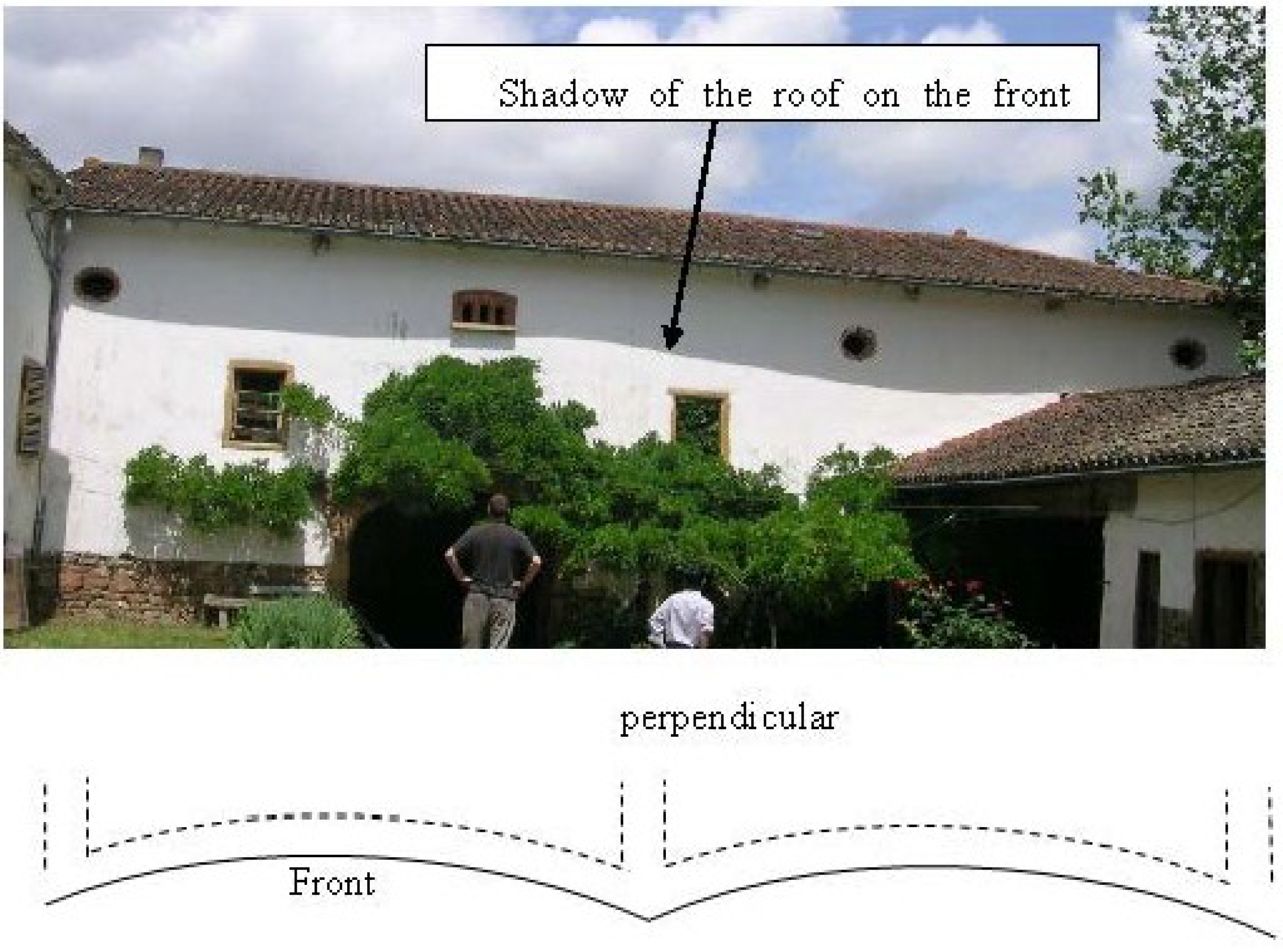
Figure 1 presents an example of a rammed earth wall which is more than 200 years old. Note that the shadow of the roof on the front wall is not a horizontal straight line. This is due to the horizontal buckling of this wall that can be seen on the plan (Figure 1, bottom). The buckling phenomenon depends on several parameters (wall’s slenderness ratio, eccentricity of the loading, boundary conditions, …) but an important parameter which relates to material’s characteristic is the creep phenomenon.
Indeed, the critical Euler buckling load Fc is given by the formula:
where E is the Young modulus, I is the moment of inertia, l0 is the buckling length of the studied wall which was discussed in the Maniatidis and Walker study [11].
Fc = π2 EI/l02
The moment due to the buckling phenomenon is a function of Fc:
where K = Fc/(Fc − F), F is the compressive load; M0 is the moment due to the initial deformation (M0 = F. y0, with y0: initial deformation).
M = K∙M0
When E decreases then Fc decreases, and M increases as well as the out-plane deflection of the wall.
It is usually observed on other geo-materials that the Young modulus varies following the time due to the ageing. Therefore, in this study, the ageing is also studied on rammed earth material. The studied rammed earth walls have been constructed and exposed for 22 years to natural weathering. Comparison of the compressive strength and the Young modulus between the walls after 22 years on site and that of the “initial” state specimens was carried out, that enables assessing the ageing of the studied walls.
2. Characterizing 22 Years Old RE Walls
2.1. Presentation of Studied Walls
The wall specimens were built in 1985 (Figure 2) thanks to the Rexcoop program, controlled by the French Scientific and Technical Building Center (CSTB), near Grenoble, in a French Alpine valley, at an altitude of 212 m. The temperature of the site can vary from −20 °C to 38 °C for some particular years and its average varies from 2 °C to 20 °C. The annual rainfall is about 1000 mm, the direction of prevailing winds is NE-SW and the maximum wind speed is 21 m/s.
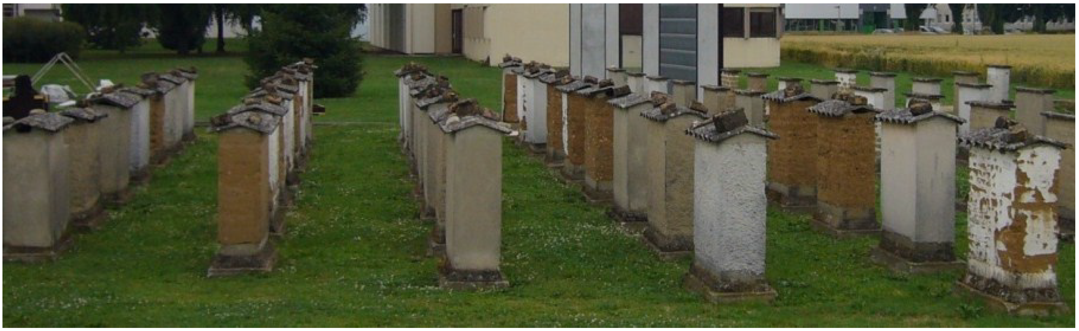
Figure 2.
Rammed earth walls constructed and exposed for 22 years to natural weathering.

A total of 104 earthen wall specimens were built using rammed earth, straw-earth, compressed earth block (CEB) masonry, and vibrated-compressed block masonry. Different types of soils were used for each of these construction techniques. Different types of surface coating were tested. This paper focuses only on rammed earth walls. All rammed earth walls were protected by asbestos cement roof. More information on these walls can be found in Bui et al. 2009 [5].
The rammed earth walls (1 m width × 1.1 m height × 0.4 m thickness) were manufactured on a concrete foundation with a 25 cm base exposed above ground level. A bituminous layer was painted on top of the base to prevent water from capillary rise penetrating into the RE walls. Local soil from a nearby site mixed with a cultivator was used for the RE walls. Three soils were used but in this study, only walls from one soil were investigated. Its grain size distribution is presented in Figure 3.
Figure 3.
Grain size distribution of the used soil.
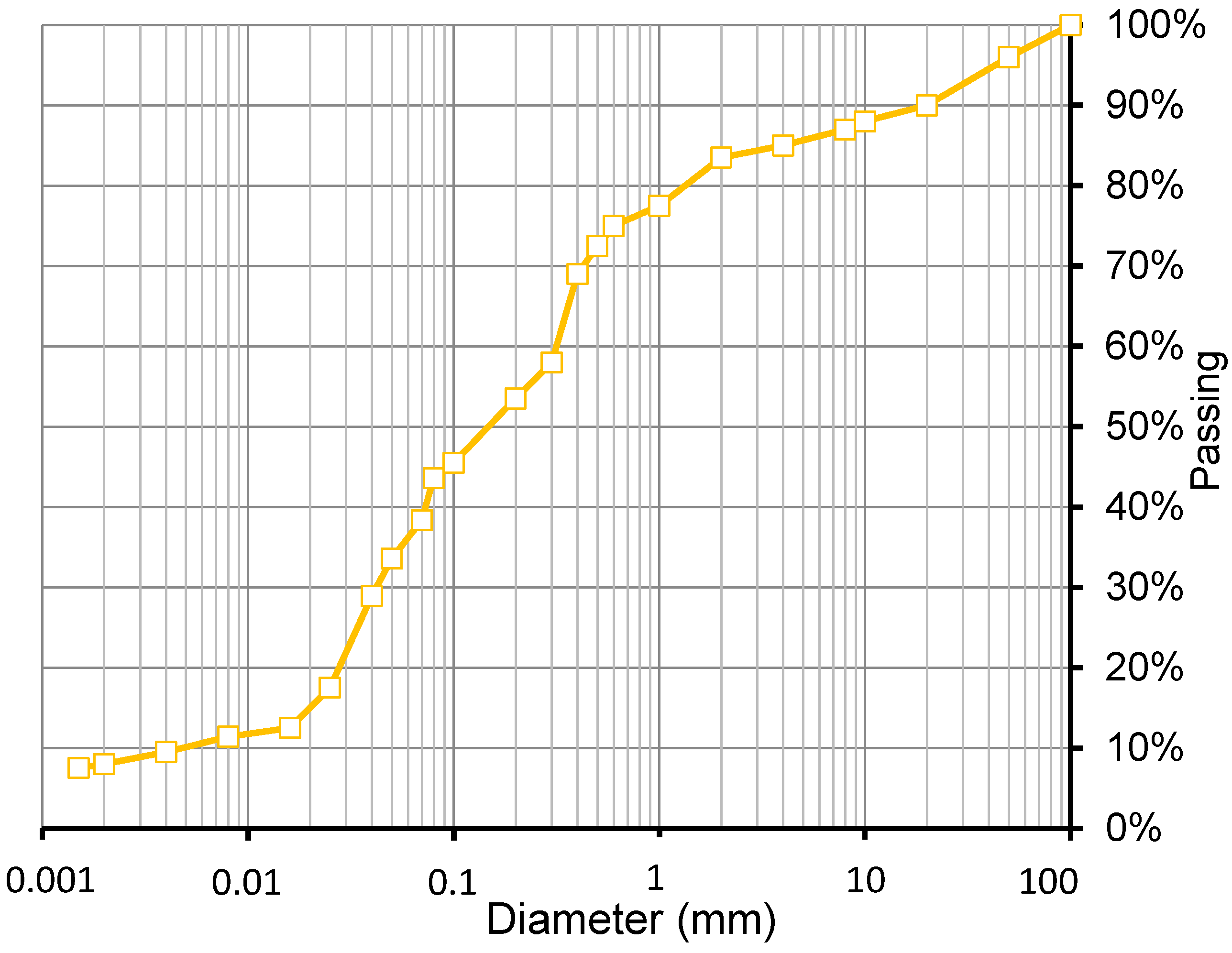
The manufacturing water content of the soil was about 10%. The metal formwork was assembled according to the wall dimensions (1 m × 0.4 m × 1.1 m high). Soil was poured into the metal formwork in 150 mm layers and then compacted with a pneumatic rammer. There was no control of the walls’ density.
The mechanical characteristics of these “old” walls were determined by two parallel approaches: firstly, in-situ dynamic measurements were carried out on the walls which enabled to identify the walls’ dynamic characteristics, and from that their Young modulus could be determined. Secondly, the studied walls had been cut, then these specimens were tested in laboratory to obtain the compressive strength and the Young modulus. Two approaches were carried out in parallel because the measurement of the Young modulus on the specimens cut from the walls was delicate [7]. The in-situ dynamic measurements could give a confirmation (or not) about the results obtained by the compression tests.
2.2. In-Situ Dynamic Measurement
2.2.1. Measurement Device
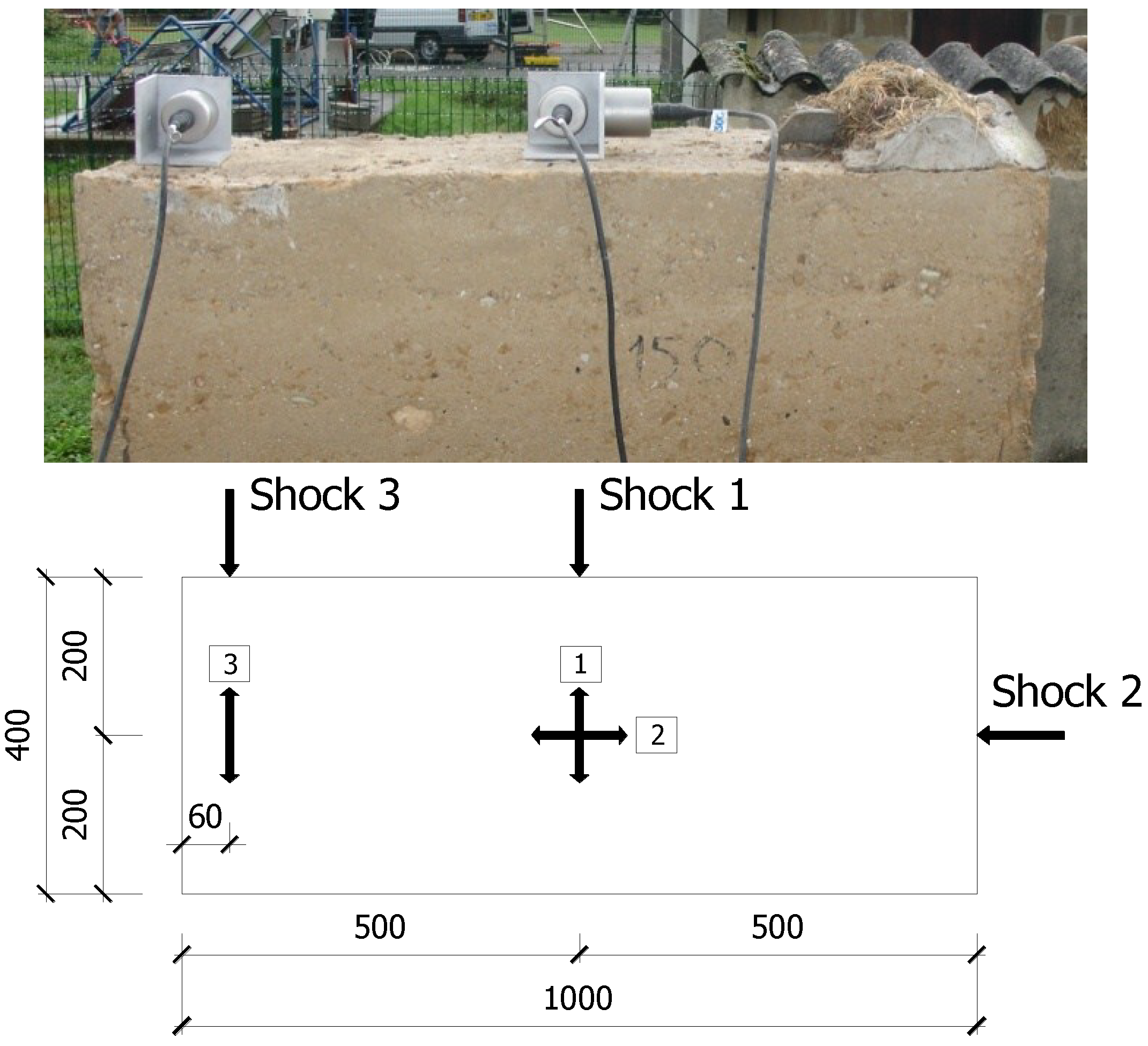
Three accelerometer sensors with a sensitivity of 1 µg (with g being the gravity field equal to 9.8 m/s2) were placed on top of the wall (Figure 4): two sensors in the centre to measure two horizontal accelerations following the two main axes of the wall; and another sensor on the edge to measure possible torsional movements.
The excitation consisted in a light shock (by a hammer) which was applied to the top of the wall. Three configurations were carried out (Figure 4, bottom): (1) a center shock following the transversal direction of the wall; (2) a center shock following the longitudinal direction of the wall; (3) an offset shock following the transversal direction. These configurations excite the possible vibration modes of the wall: transversal, longitudinal and torsional.
Figure 4.
Arrangement of the sensors on the wall A (dimensions in mm).
2.2.2. Frequencies Measured in-Situ
In the framework of this study, three RE walls were measured, 22 years after their construction. They had three different types of coating: the reference rammed earth—with no protection layer (wall A), the rammed earth protected with plaster (wall B) and the rammed earth protected with paint (wall C). Since the wall B was protected with plaster (thickness about 3–4 cm), the measurements were made after removing the plaster to eliminate its influence on the results. For the wall C protected with paint (thickness <0.5 mm), the measurements were performed without removing the protection, assuming that its contribution to the wall’s dynamic behaviour was negligible.
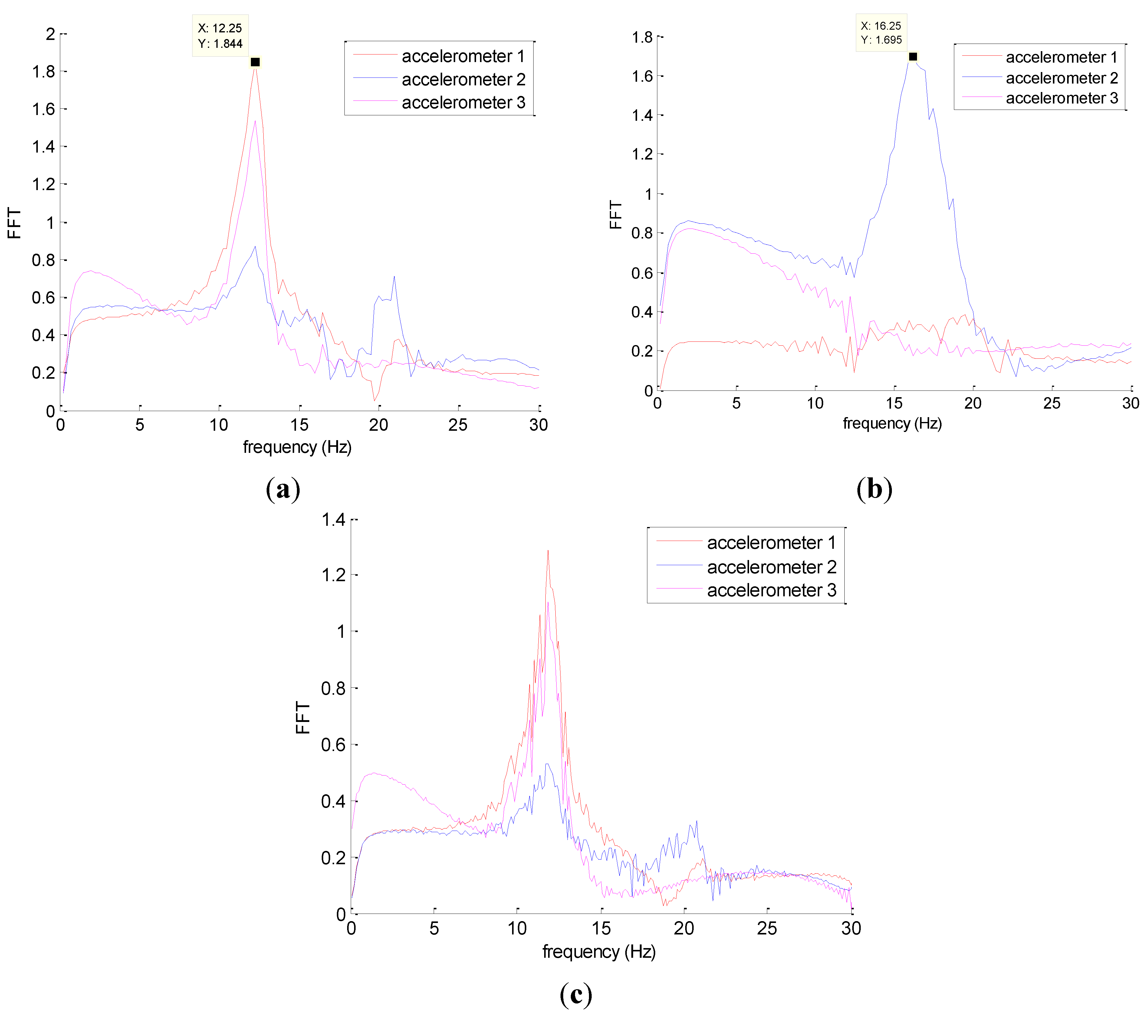
Figure 5 shows typical results obtained after a signal processing for the shocks 1, 2 and 3. Each peak corresponds to a modal frequency. In this case, the frequency of the first transversal mode is identified at 12.25 Hz. For shocks 1 and 3, sensor 2 does not give a clear signal because in these cases, excitations were perpendicular to the sensor 2; there was no major vibration in the wall’s longitudinal direction. The result for sensor 3 is similar to that of sensor 1, since the torsion was not clearly captured (shocks were not important enough to solicit this mode). For shock 2, sensors 1 and 3 do not give significant information but sensor 2 captured the second vibration mode which is in the longitudinal direction. In this case, the second modal frequency is of 16.25 Hz. Results of two others walls are presented in Table 1.
Figure 5.
A result of wall A induced by shock 1 (a); shock 2 (b); and shock 3 (c).


| Walls | Moduli identified (MPa) | Measurements | Model | ||
|---|---|---|---|---|---|
| Wall A | 104 | 12.25 ± 0.05 | 16.25 ± 0.12 | 12.25 | 16.48 |
| Wall B | 98 | 11.87 ± 0.08 | 16.20 ± 0.09 | 11.87 | 15.97 |
| Wall C | 90 | 11.38 ± 0.10 | 15.38 ± 0.22 | 11.38 | 15.31 |
2.2.3. Finite Element Modelling (FEM) of the Walls
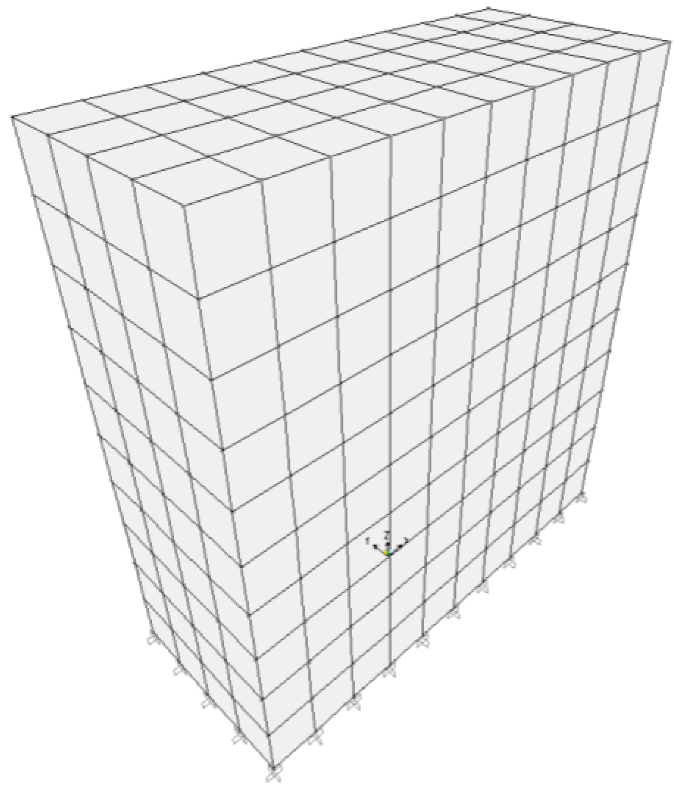
The walls are modelled with solid elements (Figure 6). Following the dynamic of structures theory, for given dimensions, the natural frequencies depend only on the density and the elastic characteristics of the material. For the modelling, the material was assumed isotropic (which is acceptable for dynamic measurements which were performed in very small strain [1]). The Poisson’s ratio was taken of 0.22 following a previous study [7]. The nodes between the RE wall and the concrete foundation were restrained in translations. This boundary condition can be justified following the results presented in the previous studies (Bui et al. [1,16], Maniatidis and Walker [11]). The principle to determine modulus from natural frequencies was presented in Bui et al. 2009 [1]:
Figure 6.
Wall A modelled with FEM.

The dry density was measured in laboratory and will be presented in Section 3.2. The results of the identified modulus are given in Table 1. The first main modes of vibration are shown in Figure 7.
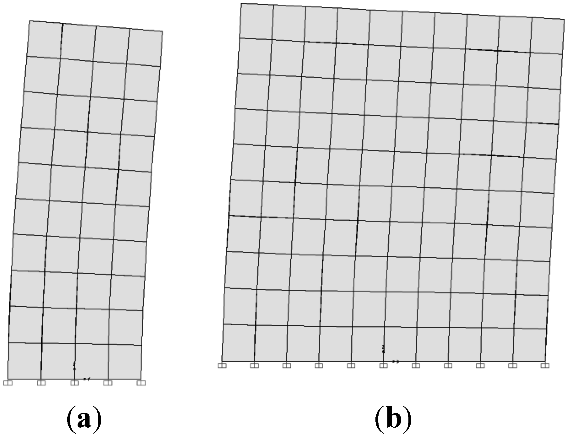
Figure 7.
First vibration modes of the wall A. (a) First vibration mode, in the transversal direction; (b) second vibration mode, in the longitudinal direction.
Figure 7.
First vibration modes of the wall A. (a) First vibration mode, in the transversal direction; (b) second vibration mode, in the longitudinal direction.
From the results presented in Table 1, the Young moduli of the measured walls were about of 100 MPa. These values are lower than that indicated in the literature (for example, Bui et al. [1] had identified moduli about 450 MPa for unstabilised rammed earth). This value of the Young modulus will be compared in the next section with that obtained by compression tests.
Following these results, the walls’ modulus values are in the order: without protection layer (wall A) > protected by plaster (wall B) > protected by paint (wall C). The worst behavior of wall covered by paint can be explained by the following reasons. On one hand, following observations on site, this type of protection was thin and stuck well to the RE surface. With temperature changes, the paint layer and the RE deformed differently, but the cohesion between the paint layers and the RE surface was stronger than the internal cohesion of the paint which was very thin. Therefore, cracks appeared quickly in these paint layers and water could penetrate easily. On the other hand, the roof could only protect the wall top, the lower part was exposed to rain drops. Due to the cracks mentioned above, the lower part of these protections was washed away by rain (Figure 8). The disappearance of the protection layer at the bottom encouraged water penetration, moving upwards by capillarity. This water could not exit because the paint inhibited the open porosity of the RE. The RE became wetter (Hall and Djerbib [8]). Indeed, after 22 years, the surface quality of that wall is worse than that of the reference wall (wall A). However, due to the limited number of the walls in this study, this observation should be tested by other investigations on other walls.
3. Laboratory Static Tests
3.1. Cutting out the Specimens
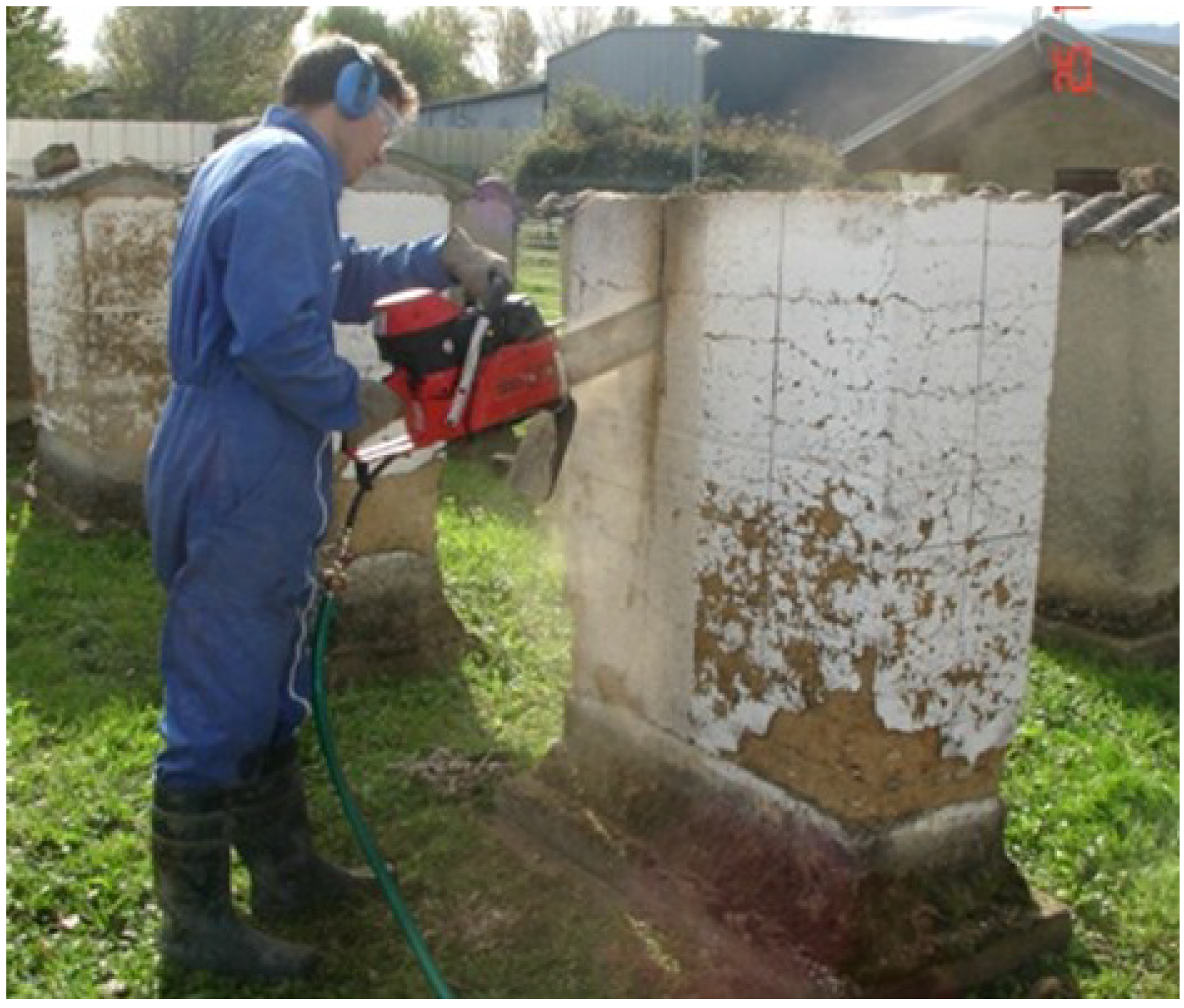
The specimens were taken from the walls using a chainsaw generally used to cut concrete and stones (Figure 8). Its blade was 30 cm long, meaning that the total thickness of the wall (roughly 41 cm) had to be cut in two steps. The disadvantages of using this method to take specimens are the generation of vibrations and the use of water, which can decrease the mechanical strength of the specimens, notably due to the splitting apart of the layers of earth.
Figure 8.
Cutting a wall with chainsaw.

3.2. Density Measurement
Since the specimens taken from the walls were roughly shaped, their density was estimated using hydrostatic weighing, once they had been coated with paraffin to seal them. Three specimens approximately (8 × 10 × 20) cm3 in size—obtained from three different walls—were measured which gave a mean dry density of 1.82 ± 0.01. The dry density value of 1.82 is lower than that of the new RE presented in a previous study, by Bui et al. 2009 [1], which was around 1.92. This lower dry density will be discussed in the next sections.
3.3. Unconfined Compression Test
The specimens cut from the walls were transported to the laboratory and re-shaped with a table saw. Several specimens were cut from the walls, but only six specimens (obtained from the cutting of all walls) had an acceptable quality for the testing. Each specimen had dimensions of (16 × 16 × 27) cm3 with a slenderness ratio of 1.7. Three were tested in the direction perpendicular to the layers, and three others in the direction parallel to the layers. The specimens was dried naturally in normal atmospheric conditions before testing, so their moisture content was similar to that of the walls.
The method using extensometers to measure strains of the central part of the specimen which had been used in the previous study Bui et al. 2014 [7] was tried but it did not work here. The extensometer did not correctly detect the strains (no strain measured or important differences between three extensometers on a specimen). This could come from the prismatic form and the surface quality of the specimens which did not enable the extensometers to operate correctly. Therefore, the strain was calculated by dividing the vertical displacement of the press by the specimen height. Because this way did not prove to be the better method to measure the strain, the above dynamic measurements were performed to check the relevancy of the results obtained by the compression tests. On the other hand, the aim of this paper to compare the results obtained on the “old” and “new” specimens, so it is an ageing factor which is researched. Call Eh: modulus measured on all height of the specimen; E1/3: modulus measured in the central part of the specimen (which is the reference case, Bui et al. 2014 [7]).
- ⇨
- Eh = K∙E1/3, where K is the correction factor to correct modulus measured on specimen height.
For “old” specimens: Ehold = K∙E1/3old. For “new” specimens: Ehnew = K∙E1/3new.
- ⇨
- E1/3new/E1/3old = Ehnew/Ehold
Therefore, the results obtained by this method can be used to investigate the ageing phenomenon. Table 2 gives the results of this test. The modulus is calculated for stress levels between 0 and 20% of the maximum stress which represent the elastic part of RE material [7]. There is no important difference in moduli between the vertical and the horizontal directions of the wall (E ≈ 95 MPa). The strength of the specimens tested in the direction parallel to layers is slightly less than that of the specimens tested in the vertical direction (8%). No major difference in two directions’ moduli shows that the isotropic hypothesis which was assumed in the FEM (for small strains) is acceptable. This remark was noted in previous studies [9,10,13].
A good correlation of the moduli obtained by the dynamic and static methods can be observed—which are around 100 MPa—confirming the relevance of the results obtained.
Table 2.
Results of the compressive strength and the elastic modulus obtained from the unconfined compression test.
| Test direction | Density | Moisture content | Ultimate stress (MPa) | Ultimate strain | E (MPa) |
|---|---|---|---|---|---|
| Perpendicular to layers | 1.82 | 1.4% | 0.89 ± 0.10 | 0.013 ± 0.001 | 98 ± 6 |
| Parallel to layers | 1.82 | 1.3% | 0.82 ± 0.08 | 0.012 ± 0.001 | 93 ± 5 |
4. Characterizing the “New” Rammed Earth
4.1. Manufacture of Specimens and Compression Tests
The soil of the specimen cut from the walls was recycled and reused for the manufacturing of the “new” specimens. In order to test the specimens in two directions (perpendicular and parallel to the layers), two types of specimens were manufactured:
- -
- Two specimens (0.4 × 0.4 × 0.7) m3
- -
- Two specimens (0.4 × 0.4 × 0.2) m3
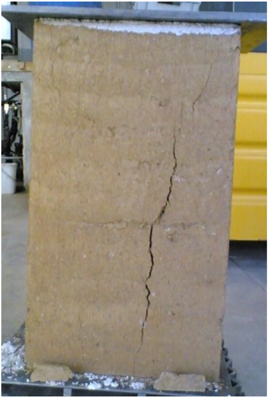
Discussions about the representativeness of specimens manufactured in laboratory were presented in the literature [1,9]. Indeed, to ensure a faithful representation of the in-situ wall material, the manufacturing mode and material used for laboratory specimens should be as identical as possible to those used in situ. The manufacturing water content and the compaction energy in the laboratory were chosen similar to that on site. The manufacturing water content was 10%. The specimens were rammed by an artisan of rammed earth with his pneumatic rammer. The dimensions of specimens tested in the direction perpendicular to the layers were 40 cm × 40 cm × 70 cm, with nine layers (Figure 9).
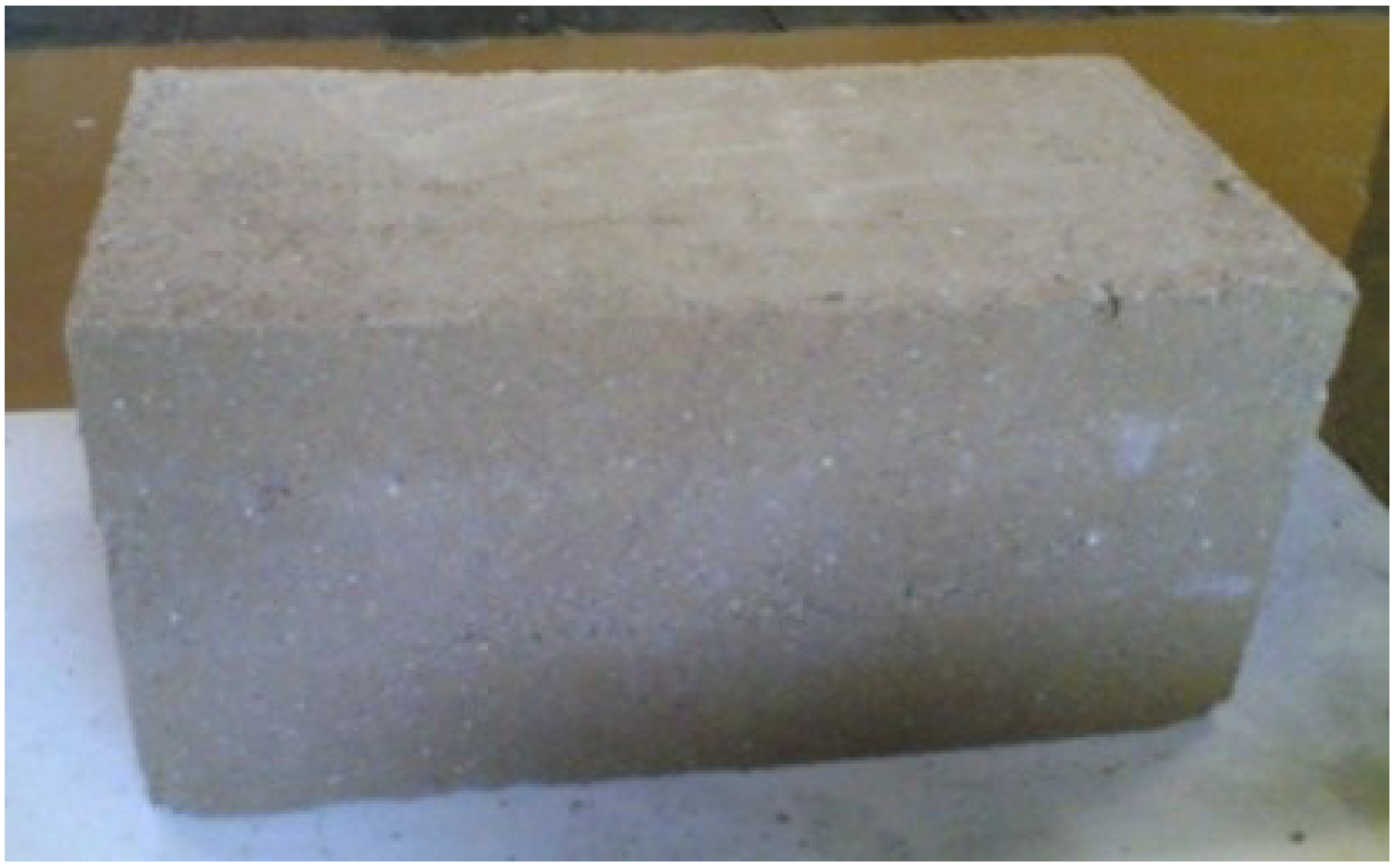
Figure 9.
A specimen (40 × 40 × 70) cm3 after the compression test.

The specimens to be tested in the parallel direction were composed of three layers; their dimensions were 40 cm × 40 cm and 20 cm high. Special attention was given during compaction of the last layer to obtain a surface that was as flat as possible. To achieve a slenderness ratio of 2, the specimens were then cut with a table saw. Two specimens (40 × 40 × 20) cm3 provided four specimens (20 × 20 × 40) cm3 for testing in the parallel direction (Figure 10). For specimens tested in the direction parallel to the layers, a surfacing was not necessary, because the two surfaces that were in contact with the formwork were sufficiently flat.
Figure 10.
A specimen (20 × 20 × 40) cm3 cut from a specimen (40 × 40 × 20) cm3.

4.2. Results
The results are presented in the Table 3. Once again, there is no significant difference between the elastic moduli of the vertical and horizontal directions of the wall (E ≈ 270 MPa). The compressive strength of the specimens tested in the direction parallel to layers is slightly less than that of the specimens tested in the perpendicular direction (8%).
| Test direction | Density | Moisture content | Ultimate stress (MPa) | Ultimate strain | E (MPa) |
|---|---|---|---|---|---|
| Perpendicular to layers | 1.91 | 1.8% | 1.35 ± 0.1 | 0.008 ± 0.001 | 263 ± 12 |
| Parallel to layers | 1.91 | 1.7% | 1.18 ± 0.1 | 0.007 ± 0.001 | 287 ± 8 |
5. Discussion and the Creep Coefficient
Except for the case of exterior walls, the in-situ walls in this study are not directly representative of current RE houses. Indeed, they have two outer surfaces, whereas in a house, the interior atmosphere (without rain) is different from the external one subjected to weathering.
The strategy which studies the initial state by manufacturing the new specimens from the recycled soil is questionable because the new ones are similar but not the same as the initial state ones. On one hand, are there possible changes in the soil’s characteristics after 22 years on site due to cycles of adsorption-desorption and freeze-thaw? On the other hand, the new specimens have a slightly higher dry density than that of the old walls. There are two possible reasons for this: firstly, compaction energy which depends on the artisan experience is higher in the case of the new specimens. Secondly, there is a possible change in the porosity of the walls due to the adsorption-desorption and freeze-thaw cycles [25,26]. If the second reason is confirmed, it will be an interesting element in investigations on the ageing effects of rammed earth walls.
Due to the difference of the dry density (about 5%) between the old walls and the new specimens, there is a difference in the corresponding compressive strength (about 50%). This result is not surprising and was observed in the literature [27]. The interesting remark is the difference in the Young moduli: the new specimens had moduli which were 2.7 times greater than the ones of the old walls (instead of 1.5 for the compressive strength). We analyse the difference in stiffness:
- -
- damage of the sample during the “old” specimens’ taking: however, the in-situ dynamic tests give the similar results of modulus. So, it is not this possibility.
- -
- Problem of representativeness of the “new” specimens: there are also possible differences in the compaction energy, the manufacturing water content between the “old” walls and the “new” specimens. Although the walls and the new specimens were all manufactured by the rammed earth professionals, a difference is not evitable. However, in our opinion, this difference cannot be the only factor which can cause a significant difference in the dry density.
- -
- Propagation of micro-cracks under weathering loadings: there are changes at the micro-structure of the material: micro-pores increase which lead to a decrease of dry density.
So, the second and third reasons are the probable factors. The third is the ageing phenomenon which has a link to the creep phenomenon. Indeed, for concrete, the creep occurs at all stress levels and, within the service stress range, is linearly dependent on the stress if the pore water content is constant [24]. For rammed earth, the increase of strain under a constant stress was noted in Lombillo et al. study [28] and compared to the phenomenon of consolidation of normally consolidated soil.
The creep depends on the ambient humidity, composition of the RE material, age of material, duration and intensity of the loading. In the case of the studied walls, the creep due to the loading was negligible because the stress levels were low but the creep due to the weathering could take place.
For concrete, following Eurocode 2 [24], the effective modulus Eeff is related to the initial modulus Et0 (at 28 days) by the formula:
where φ is the creep coefficient,
Eeff = Et0/[1 + φ]
φ = Et0/Eeff – 1
If the modulus of the walls and the new specimens are used respectively for Eeff and Et0, the corresponding creep coefficient of the walls is 1.7. This information is interesting because, to our knowledge, this is the first time a value of RE creep coefficient is presented.
In the last decade, to explain the basic creep of concrete, physical mechanisms taking action at the scale of the hydrates were proposed; they are based on the microprestress-solidification theory, the viscoplastic behaviour of the hydrates (principally the C–S–H which is the principal component of the cement), and the rearrangement of nanoscale particles (C–S–H level) following the free-volume dynamics theory of granular physics (a synthesis can be found in Rossi et al. [29]). However, in the case of RE, these theories cannot explain its creep because there are not C–S–H particles. A recent proposal by Rossi et al. [29] showed that even other physical mechanisms can exist; the main physical origins of the basic creep are related to the microcracking propagation under load. In the case of RE, when a wall is under a loading (self-weight, wind, temperature, freeze-thaw), it cracks. The microcracks generate a severe hygric imbalance within the material. Indeed, creation of microcracks provokes the appearance of vacuums effect (gradients of pressure) and local hygric shocks (gradients of concentration in water molecule). That is why there is a propagation of the initial microcracks. The microcrack propagation is suggested to be the main factor for the decrease of the Young modulus of RE material. The decrease of the Young modulus due to the increase of the porosity had been reported in the Wang and Li study (2007) for concrete material [30].
6. Conclusions and Outlook
In this study, the ageing effects on 22 years old RE walls were studied. Mechanical characteristics of these “old” walls were determined by in-situ dynamic measurements and by laboratory compression tests. Then, soil was reused to manufacture the new specimens with the same way as the old walls.
There are several factors which influence the creep phenomenon: Material and ambiance: the composition of the material; the rate of hardening of the material; the dimensions of the element; ambient humidity; ambient temperature; Loading: age of the material at loading; the duration of the loading and the stress level. In the case of the studied walls, the creep due to the loading was negligible because the stress levels were low but the creep due to the weathering was observed.
The strategy which studies the initial state by manufacturing the new specimens from the recycled soil is questionable. However, it is always interesting to have direct information from real walls exposed to natural conditions. For the walls studied in this paper, a creep coefficient was obtained. However, this is a first exploratory study on the ageing and creep of RE walls, so the results should be confirmed by other studies in the future. Two other approaches are planned the next time: first, other new specimens will be manufactured to have the same dry density as the old walls; second, acceleration tests [29] which are currently used for creep studies of concrete will be applied.
Acknowledgments
The authors wish to thank the French national research agency ANR for the funding of this project (PRIMATERRE-ANR-12-VBDU-0001-01- Villes et Bâtiments Durables). The authors wish also to acknowledge the support of Jacques Chevalier, Hébert Sallée and Marcel Rubaud from Grenoble CSTB; Stéphane Hans and Sébastien Courrier from Ecole Nationale des Travaux Publics de l’Etat.
Author Contributions
Quoc-Bao Bui did the experiments, data analysis and wrote this paper. Jean-Claude Morel wrote partly this paper and contributed to data analysis.
Conflicts of Interest
The authors declare no conflict of interest.
References
- Bui, Q.B.; Morel, J.C.; Hans, S.; Meunier, N. Compression behaviour of nonindustrial materials in civil engineering by three scale experiments: The case of rammed earth. Mater. Struct. 2009, 42, 1101–1116. [Google Scholar] [CrossRef]
- Walker, P.; Keable, R.; Martin, J.; Maniatidis, V. Rammed Earth-Design and Construction Guidelines; BRE Bookshop: Watford, UK, 2005. [Google Scholar]
- Habert, G.; Castillo, E.; Vincens, E.; Morel, J.C. Power: A new paradigm for energy use in sustainable construction. Ecol. Indic. 2012, 23, 109–115. [Google Scholar] [CrossRef]
- Allinson, D.; Hall, M. Hygrothermal analysis of a stabilised rammed earth test building in the UK. Energy Build. 2010, 42, 845–852. [Google Scholar] [CrossRef]
- Bui, Q.B.; Morel, J.C.; Reddy, B.V.V.; Ghayad, W. Durability of rammed earth walls exposed for 20 years to natural weathering. Build. Environ. 2009, 44, 912–919. [Google Scholar] [CrossRef]
- Fodde, E. Traditional earthen building techniques in Central Asia. Int. J. Archit. Herit. 2009, 3, 145–168. [Google Scholar] [CrossRef] [Green Version]
- Bui, Q.B.; Morel, J.C.; Hans, S.; Walker, P. Effect of moisture content on the mechanical characteristics of rammed earth. Constr. Build. Mater. 2014, 54, 163–169. [Google Scholar] [CrossRef]
- Hall, M.; Djerbib, Y. Moisture ingress in rammed earth: Part 1-the effect of soil particle—Size distribution on the rate of capillary suction. Constr. Build. Mater. 2004, 18, 269–280. [Google Scholar] [CrossRef]
- Bui, Q.B.; Morel, J.C. Assessing the anisotropy of rammed earth. Constr. Build. Mater. 2009, 23, 3005–3011. [Google Scholar] [CrossRef]
- Bui, T.T.; Bui, Q.B.; Limam, A.; Morel, J.C. Modelling rammed earth wall by discrete element method. In Proceeding of the ICREC 2015, Perth, Australia, 11–13 February 2015.
- Maniatidis, V.; Walker, P. Structural capacity of rammed earth in compression. J. Mater. Civ. Eng. 2008, 20, 230–238. [Google Scholar] [CrossRef]
- Walker, P.; Dobson, S. Pullout tests on deformed and plain rebars in cement stabilized rammed earth. J. Mater. Civ. Eng. 2001, 13, 291–297. [Google Scholar] [CrossRef]
- Bui, T.T.; Bui, Q.B.; Limam, A.; Maximilien, S. Failure of rammed earth walls: From observations to quantifications. Constr. Build. Mater. 2014, 51, 295–302. [Google Scholar] [CrossRef]
- Cheah, J.S.J.; Walker, P.; Heath, A.; Morgan, T.K.K.B. Evaluating shear test methods for stabilised rammed earth. Constr. Mater. 2012, 165, 325–334. [Google Scholar] [CrossRef] [Green Version]
- Silva, R.A.; Oliveira, D.V.; Miranda, T.; Cristelo, N.; Escobar, M.C.; Soares, E. Rammed earth construction with granitic residual soils: The case study of northern Portugal. Constr. Build. Mater. 2013, 47, 181–191. [Google Scholar] [CrossRef] [Green Version]
- Bui, Q.B.; Morel, J.C.; Hans, S.; Do, A.-P. First exploratory study on dynamic characteristics of rammed earth buildings. Eng. Struct. 2011, 33, 3690–3695. [Google Scholar] [CrossRef]
- Gomes, M.I.; Lopes, M.; Brito, J. Seismic resistance of earth construction in Portugal. Eng. Struct. 2011, 33, 932–941. [Google Scholar] [CrossRef]
- Ciancio, D.; Augarde, C. Capacity of unreinforced rammed earth walls subject to lateral wind force: Elastic analysis versus ultimate strength analysis. Mater. Struct. 2013, 46, 1569–1585. [Google Scholar] [CrossRef] [Green Version]
- Standards New Zealand. NZS 4297:1998, Engineering Design of Earth Buildings; Standards New Zealand: Wellington, New Zealand, 1998. [Google Scholar]
- Taylor, P.; Fuller, R.J.; Luther, M.B. Energy use and thermal comfort in a rammed earth office building. Energy Build. 2008, 40, 793–800. [Google Scholar] [CrossRef]
- Taylor, P.; Luther, M.B. Evaluating rammed earth walls: A case study. Sol. Energy 2004, 76, 79–84. [Google Scholar] [CrossRef]
- Chabriac, P.A.; Fabbri, A.; Morel, J.C.; Laurent, J.P.; Blanc-Gonnet, J. A procedure to measure the in-situ hygrothermal behavior of earth walls. Materials 2014, 7, 3002–3020. [Google Scholar] [CrossRef]
- Paul, W.L.; Taylor, P.A. A comparison of occupant comfort and satisfaction between a green building and a conventional building. Build. Environ. 2008, 43, 1858–1870. [Google Scholar] [CrossRef]
- EN 1992-1-1, Eurocode 2. Design of Concrete Structures—Part 1–1: General Rules and Rules for Buildings, 2005.
- Aubert, J.E.; Gasc-Barbier, M. Hardening of clayey soil blocks during freezing and thawing cycles. Appl. Clay Sci. 2012, 65–66, 1–5. [Google Scholar] [CrossRef]
- Grossein, O. Modélisation et Simulation Numérique des Transferts Couplés d’eau, de Chaleur et de Solutés Dans le Patrimoine Architectural en Terre, en Relation Avec sa Dégradation. Ph.D. Thesis, Université Joseph Fourier, Grenoble, France, 2009. [Google Scholar]
- Morel, J.C.; Pkla, A.; Walker, P. Compressive strength testing of compressed earth blocks. Constr Build. Mater. 2007, 21, 303–309. [Google Scholar] [CrossRef]
- Lombillo, I.; Villegas, L.; Fodde, E.; Thomas, C. In situ mechanical investigation of rammed earth: Calibration of minor destructive testing. Constr. Build. Mater. 2014, 51, 451–460. [Google Scholar] [CrossRef]
- Rossi, P.; Charron, J.P.; Bastien-Masse, M.; Tailhan, J.L.; le Maou, F.; Ramanich, S. Tensile basic creep versus compressive basic creep at early ages: Comparison between normal strength concrete and a very high strength fibre reinforced concrete. Mater. Struct. 2014, 47, 1773–1785. [Google Scholar]
- Wang, H.; Li, Q. Prediction of elastic modulus and Poisson’s ratio for unsaturated concrete. Int. J. Solids Struct. 2007, 44, 1370–1379. [Google Scholar] [CrossRef]
© 2014 by the authors; licensee MDPI, Basel, Switzerland. This article is an open access article distributed under the terms and conditions of the Creative Commons Attribution license (http://creativecommons.org/licenses/by/4.0/).
Share and Cite
MDPI and ACS Style
Bui, Q.-B.; Morel, J.-C. First Exploratory Study on the Ageing of Rammed Earth Material. Materials 2015, 8, 1-15. https://doi.org/10.3390/ma8010001
AMA Style
Bui Q-B, Morel J-C. First Exploratory Study on the Ageing of Rammed Earth Material. Materials. 2015; 8(1):1-15. https://doi.org/10.3390/ma8010001
Chicago/Turabian StyleBui, Quoc-Bao, and Jean-Claude Morel. 2015. "First Exploratory Study on the Ageing of Rammed Earth Material" Materials 8, no. 1: 1-15. https://doi.org/10.3390/ma8010001