Influence of Hydrogen on Steel Components for Clean Energy
by
Andrej Atrens
1,*, 
Qian Liu
1,
Clotario Tapia-Bastidas
2,3,
Evan Gray
2,
Bartolomeus Irwanto
4,
Jeff Venezuela
1 and 
Qinglong Liu
1 1
School of Mechanical and Mining Engineering, The University of Queensland, St. Lucia, QLD 4072, Australia
2
Queensland Micro- and Nanotechnology Centre, Griffith University, Brisbane, QLD 4111, Australia
3
Faculty of Mechanical Engineering and Production Science, Escuela Superior Politécnica del Litoral ESPOL, Campus Gustavo Galindo Km. 30.5 Vía Perimetral, P.O. Box 09-01-5863, Guayaquil, Ecuador
4
General Electric (Switzerland) GmbH, CH-5242 Birr, Switzerland
*
Author to whom correspondence should be addressed.
Corros. Mater. Degrad. 2020, 1(1), 3-26; https://doi.org/10.3390/cmd1010002
Submission received: 24 May 2018
/
Revised: 7 June 2018
/
Accepted: 8 June 2018
/
Published: 13 June 2018
Abstract
:The influence of hydrogen on the mechanical properties of four, medium-strength, commercial, quenched-and-temped steels has been studied using the linearly increasing stress test (LIST) combined with cathodic hydrogen charging. The relationship was established between the equivalent hydrogen pressure and the hydrogen charging overpotential during cathodic hydrogen charging, though the use of electrochemical permeation experiments and thermal desorption spectroscopy. The cathodic hydrogen charging conditions were equivalent to testing in gaseous hydrogen at hydrogen fugacities of over a thousand bar. Under these hydrogen-charging conditions, there was no effect of hydrogen up to the yield stress. There was an influence of hydrogen on the final fracture, which occurred at the same stress as for the steels tested in air. The influence of hydrogen was on the details of the final fracture. In some cases, brittle fractures initiated by hydrogen, or DHF: Decohesive hydrogen fracture, initiated the final fracture of the specimen, which was largely by ductile micro-void coalescence (MVC), but did include some brittle fisheye fractures. Each fisheye was surrounded by MVC. This corresponds to MF: Mixed fracture, wherein a hydrogen microfracture mechanism (i.e., that producing the fisheyes) competed with the ductile MVC fracture. The fisheyes were associated with alumina oxide inclusion, which indicated that these features would be less for a cleaner steel. There was no subcritical crack growth. There was essentially no influence of hydrogen on ductility for the hydrogen conditions studied. At applied stress amplitudes above the threshold stress, fatigue initiation, for low cycle fatigue, occurred at a lower number of cycles with increasing hydrogen fugacity and increasing stress amplitude. This was caused by a decrease in the fatigue initiation period, and by an increase in the crack growth rate. In the presence of hydrogen, there was flat transgranular fracture with vague striations with some intergranular fracture at lower stresses. Mechanical overload occurred when the fatigue crack reached the critical length. There was no significant influence of hydrogen on the final fracture.
Keywords:
hydrogen; steel; hydrogen permeation; hydrogen characterization; Sieverts’ law; TDS; LIST; fatigue1. Introduction
1.1. Aims
This review is based on the following papers [1,2,3,4,5,6,7,8,9,10,11], the PhD theses of Qian Liu [12] and Clotario Tapia-Bastidas [13], and informed by recent research [14,15,16,17,18,19,20,21,22,23,24,25,26,27,28,29,30,31,32,33,34,35,36,37,38,39,40,41,42,43,44,45,46,47,48,49,50,51,52,53,54,55,56,57,58,59,60,61,62,63,64,65,66,67,68,69,70,71,72,73,74,75].
Operation of metallic components is required in hydrogen (H) in the hydrogen (H) economy, which is being developed in response for the need for clean energy. The H economy will require pressure vessels resistant to hydrogen embrittlement (HE) for the production, distribution, storage and use of gaseous H2. Laboratory scale vessels can be made from expensive exotic materials like nickel base superalloys, whereas there are significant cost imperatives to use less expensive materials like steels in a commercial H economy.
However, hydrogen (H) has caused failures of stressed metallic components, particularly steel components. This is hydrogen embrittlement (HE) [1,14,15,76,77,78].
The aim of this paper was to understanding HE for steels for the H economy.
The aim was pursued by studying the hydrogen influence of a range of steels, in order to identify commercial steels suitable for reliable H use. At the project start this knowledge did not exist. The steels studied were identified as having a high expectation of having good performance in gaseous hydrogen.
The following key targets were pursued (i) proof of H loading, and (ii) mechanical properties under H influence, under both static and dynamic loading conditions.
To meet the first target, a new improved thermal desorption spectroscopy (TDS) Apparatus was built [9,10] to (i) measure the total amount of H in the steel samples, and (ii) study H-trap interactions.
This research was based on past research (i) in evaluating steel properties under the influence of H [79,80,81,82,83,84,85]], (ii) in evaluating H diffusion [86], (iii) on HE and stress corrosion cracking (SCC) [87,88,89,90,91,92,93,94,95,96,97,98,99,100,101,102,103,104,105], and related research [106,107,108,109,110,111].
1.2. Background
1.2.1. H Economy
Hydrogen (H) is a logical endpoint in the historical sequence of fuels: wood-peat-coal-oil-natural gas. However, H is not an energy source. H needs to be produced in an environmentally sustainable route. The H economy is the proposed global energy system in which H is the universal reversible energy vector, produced from water and combusted to water. All sectors of the H economy require HE resistant materials, which, to be economical, need to be steels.
1.2.2. Hydrogen Embrittlement
Hydrogen Embrittlement (HE) is a particularly dangerous and unpredictable manifestation of the degradation of material properties by the local environment, which is gaseous H2 in this case. HE occurs because atomic H at the ppm level can drastically change the local properties of the metallic lattice. HE has caused sudden, catastrophic fracture in plant and machinery [112]. HE can initiate and grow subcritical cracks, just as in the related phenomenon of stress corrosion cracking (SCC). Fast fracture occurs when the crack reaches a critical length (~2 mm for rock bolts) determined by fracture toughness and the applied stress. Fast fracture is sudden and can be catastrophic. In 1985, SCC caused the collapse of the concrete roof of a Swiss indoor swimming pool, killing 12 people [113].
However, recent work [16,17,21,24,25] has indicated that HE is not the most appropriate descriptor for lower strength steels in which there is no hydrogen induced subcritical crack growth. In these steels the influence of hydrogen on mechanical properties is to (i) decrease the yield strength (by 0% to 30%), and (ii) introduce hydrogen assisted micro-mechanisms of fracture when the steel is stressed to the ultimate tensile strength, has become mechanically unstable, and is undergoing fast ductile fracture. The decrease of the yield stress occurs by hydrogen interacting with the whole volume of the gauge part of the specimen, and is designated hydrogen enhanced macroscopic plasticity (HEMP). The introduction of extra micro-mechanisms of fracture is designated as HAM, hydrogen assisted micro-fracture. The extra hydrogen induced micro-mechanisms of fracture occur under the following conditions: (i) PHF: Plastic hydrogen fracture, for cases when the fracture is caused by the plasticity facilitated by hydrogen, (ii) DHF: Decohesive hydrogen fracture, for cases where the fracture is caused by decohesion facilitated by hydrogen, and (iii) MF: Mixed fracture, where hydrogen facilitated micro-mechanisms (including fisheyes) complete with simultaneously occurring ductile fracture proceeding by micro-void coalescence. In each cause, the hydrogen assisted micro-fracture is caused by an interaction of hydrogen and the stress/stain field.
1.2.3. Testing Methodologies
Our prior research on rock bolt SCC developed a methodology to evaluate material properties under controlled H conditions. A sample is subjected to a linearly increasing stress test (LIST), until fracture [2,3,92,93]. More details about the LIST are given later in Section 3. H Influence—static strength. The steel fails either in a brittle manner if H degrades the mechanical properties or in a ductile manner if H causes no property degradation [79,80,81,82,83]. The amount of H (and the H fugacity) increases with increasingly negative electro-chemical potential and HE increases in severity with increasing H.
Based on our prior experience in the characterization of H in materials, we designed an improved state-of-the-art Thermal Desorption Spectroscopy (TDS) instrument [9,10] to (i) enable study of H-trap interactions in relation to HE in steels and (ii) provide a direct measurement of the amount of H in steels.
1.3. Significance
The significant problem addressed herein was HE of metallic components for clean energy. The scale is global and the present paucity of affordable H-proof materials poses strong technological and economic barriers to the H economy. HE of pipeline steels for distribution of H-containing gases (H2, syngas, natural gas + H2) is a particularly significant example. Can existing natural gas networks be incrementally taken over by adding H2 to the supply?
Part of the significance therefore resides in identification of medium-strength-steels suitable for H service.
Another part of the significance of the present work is the assessment of HE risk for steels in current use.
1.4. Approach
This paper is structured to deal with the following three issues.
1.4.1. Hydrogen Characterization
The issue is (i) to evaluate, using TDS, the amount of H in H-changed specimens of the steels listed in Table 1 to provide “proof of H loading”, and (ii) to characterize the hydrogen within the steel using the TDS and the electrochemical permeability cell.
It was proposed that “proof of H loading” was best done by a direct measurement of the H in the sample. The current technological technique, used for at least the last 30 years, was the LECO hot extraction method [114], which measures the amount of H released from a sample during rapid melting. TDS is a major refinement of the LECO method in that TDS measures the amount of H released from the samples as the sample is heated through the temperature range in which H is de-trapped, typically room temperature to 700 °C. TDS measures the rate of H release as a function of temperature. Peaks in the amount of released H are assigned to H de-trapped from particular H traps, such as dislocations, grain boundaries, precipitates etc. Integrating the TDS spectrum measures the total H desorbed, subject to calibration of the instrument.
No TDS that resolved ppm amounts of H existed in Australia. There are few in the world. They are typically purpose-built in connection with a research program on H-material interactions, or more recently bought specifically for such a program. The most satisfactory way to accomplish H detection as to sensitivity is to use a mass spectrometer tuned to mass 2, coupled to an ultra-high vacuum system and a furnace. We proposed an improved self-calibrating version of the state-of-the-art system described by Smith and Scully [115]. In our modification [9,10], a source of highly pure H2 gas (a metal hydride) and a highly accurate pressure transducer (Barocel, 6 Pa full scale) are connected to the sample space through a calibrated volume and leak valve, providing an accurately known rate of H to the analyzer. Thus the analyzer can be calibrated automatically at any time.
To evaluate the H charging conditions and the H diffusion and solubility, for the steels listed in Table 1, we used the electrochemical permeability approach, as per Atrens et al. [8]. H-charging conditions are established on the left side of the specimen in the electrochemical permeability cell [4,5]. The amount of H exiting the right hand side is measured as a current. The H transient is analyzed to give the effective diffusion coefficient, Deff. The steady state amount of H in the measured H transient is related to the H solubility in the steel for the particular H charging conditions. This, together with the TDS research, allows calibration of the charging conditions: e.g., the applied electrochemical potential can be related to the equivalent H pressure for conditions of exposure to gaseous H2 in service. The effective H diffusion coefficient gives information about H trapping in the steel, and consequently how quickly hydrogen penetrates the steel.
Thus hydrogen characterization included: (i) The measurement of the amount of hydrogen in the steel for the particular hydrogen charging conditions used, (ii) the relationship between gaseous hydrogen charging and electrochemical hydrogen charging, (iii) the characterization of the hydrogen dissolved in the steel (in terms of concentration and trapping), and (iv) how quickly the hydrogen moved into and within the steel.
1.4.2. H Influence—Static Strength
The requirement was to evaluate the influence on the mechanical properties of H on the steels in Table 1 using the approach of Villalba and Atrens [79] developed in prior research; that is, to determine the influence of hydrogen on the strength and ductility of these steels. The approach was to use the linearly increasing stress test (LIST) for samples exposed to a dilute pH 2.1-sulphate solution, at their free corrosion potential and at increasingly negative applied potentials to −1500 mV. The increasingly negative applied potential increases the aggressivity, because increasing H is liberated at the specimen surface. The influence of H is evaluated from the decrease in tensile strength, ductility and fractography as revealed by scanning electron microscopy. Our prior work [79,80,81] had shown that the steels 1008, X65, X70 and 4145H were resistant for all applied potentials including −1500 mV. The evaluation included steels, which show an influence of H; for such steels, the threshold stress is measured, σH, above which there is subcritical crack growth due to H. For high strength steels, unexpected catastrophic failures can occur at stress otherwise considered to be safe, because the threshold stress, σH, may be considerably below the yield stress [92,95,96]. For Mg–Al alloys stressed in distilled water, the threshold stress is about half the yield stress [97,98,100]. The factors determining structural integrity under static loading are the operating stress, σH and K1H. Understanding the influence of H on these standard high-performance steels was expected to assist in the understanding of steels of importance to the H economy.
1.4.3. H Influence—Fatigue
2. Hydrogen Characterization
2.1. Permeation Cell
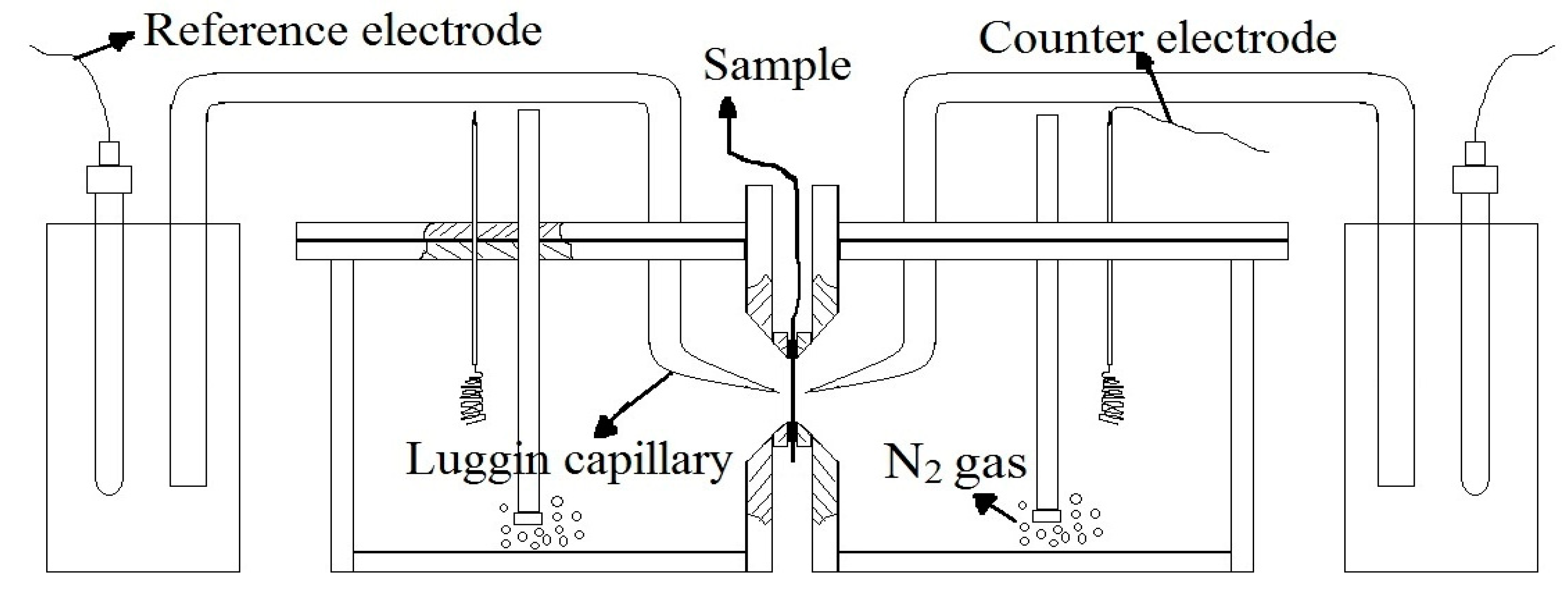
The aims included: (i) understand how quickly hydrogen enters these steels, and (ii) relate cathodic hydrogen charging to gaseous hydrogen charging. Figure 1 illustrates the permeation cell [4,86], which is widely used [19,20,22,23,117,118,119,120,121,122,123,124,125,126,127,128,129,130,131,132,133,134], and was used in this research project. Hydrogen is produced by the applied cathodic potential on the left hand side of the specimen, by the electrochemical cell on the left hand side of the specimen. The hydrogen diffuses through the specimen, and is detected as a permeation current by the electrochemical cell on the right hand side of the specimen.
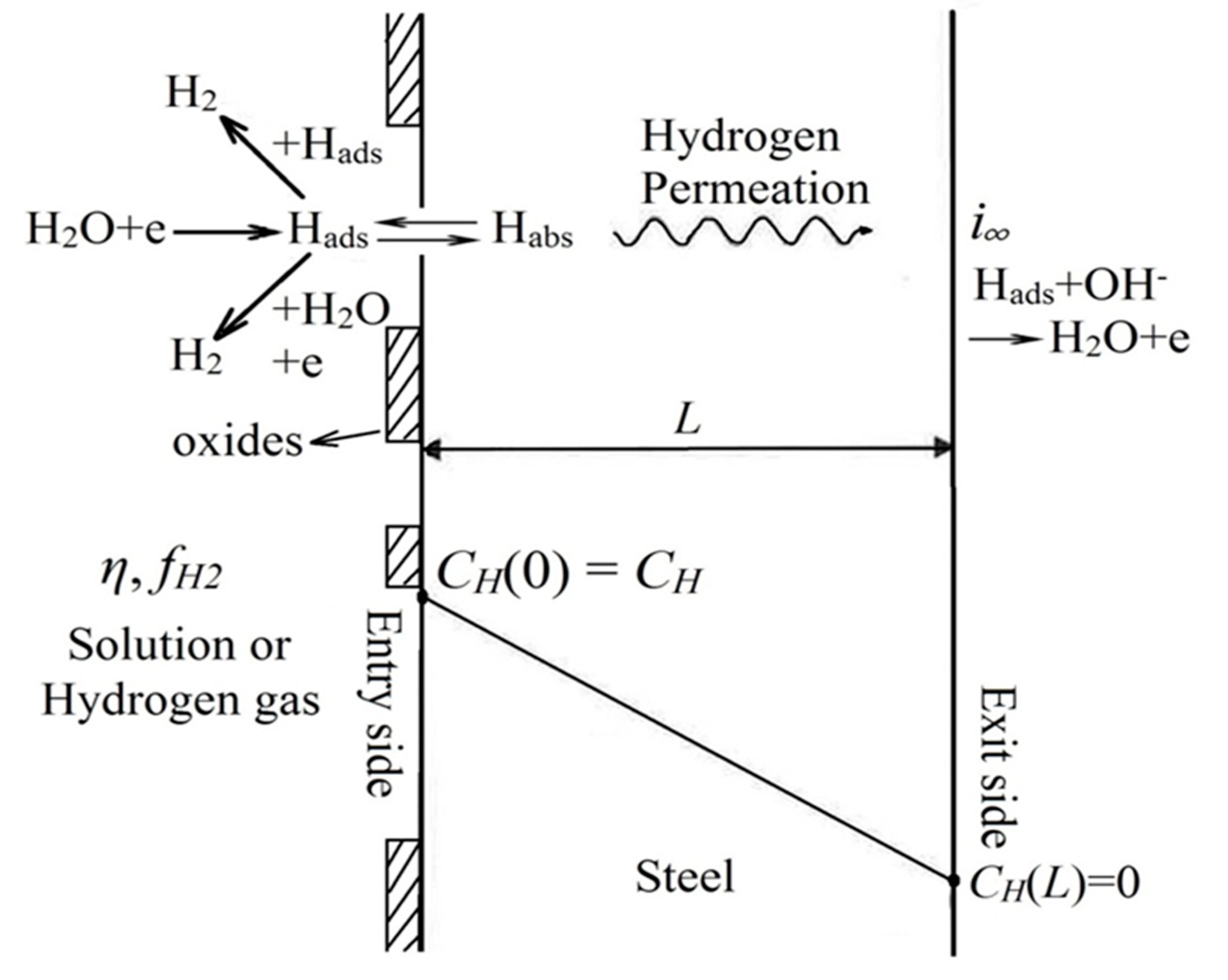
Figure 2 provides details of the permeation specimen [4,135]. Hydrogen is evolved at the specimen surface by:
where MHads represents a H atom on the metal surface, M. Most of the adsorbed hydrogen bubbles off the surface after adsorbed hydrogen atoms have recombined to hydrogen molecules by the following:
H2O + M + e → MHads + OH−
2MHads ↔ H2 + 2M
The adsorbed hydrogen is in equilibrium with hydrogen in the steel, by the following:
where MHabs is hydrogen dissolved in the steel.
MHads ↔ MHabs
The modified Nernst equation indicates that the hydrogen activity (fugacity) is given by [4]:
where η, is the charging over-potential, F is the Faraday constant, R is the gas constant, T is the absolute temperature and the constants are A and ξ. Thus, fugacity increases exponentially with over-potential. The hydrogen activity is designated as the hydrogen fugacity, which is equal to the hydrogen pressure at low pressures (up to about 100 bar). At higher hydrogen pressures there is an increasing difference between the hydrogen pressure and the hydrogen fugacity (see Figure 12).
Hydrogen charging can be by cathodic charging or by gaseous charging. The two hydrogen-charging conditions are equivalent if they produce the same hydrogen concentration dissolved in the steel. This leads to the expectation that the steady-state permeation current density is given by [4]:
where S is the Sieverts’ constant and L is the thickness of the permeation specimen. This means that a series of permeation experiments that measure the steady-state permeation current density as a function of charging over-potential can be used to determine the unknown quantities in Equation (5) and so provide a determination of hydrogen fugacity by Equation (4).
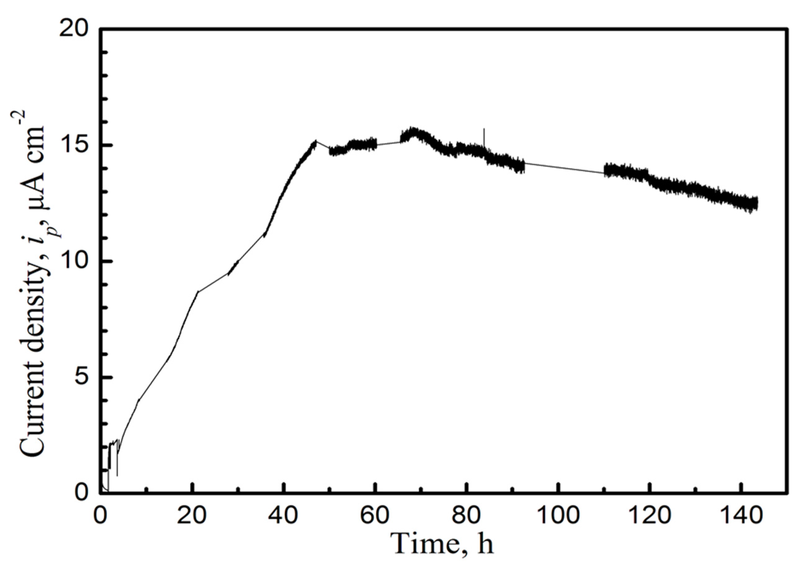
Figure 3 demonstrates surface conditioning of the pure Fe specimen. This plots the permeation current density as a function of time as a permeation specimen is hydrogen charged on the input side. There are slow increases in the permeation current density for pure iron until quasi-steady state is reached after about 48 h. The specimen was pure iron as annealed low interstitial steel. There is an oxide on the surface of a steel specimen if it has been exposed to air, as is indicated in Figure 2. This oxide film is reduced by the hydrogen evolved at the specimen surface or by the reduction reaction on the electrode surface, but this reduction is a slow process, as shown by Figure 3.
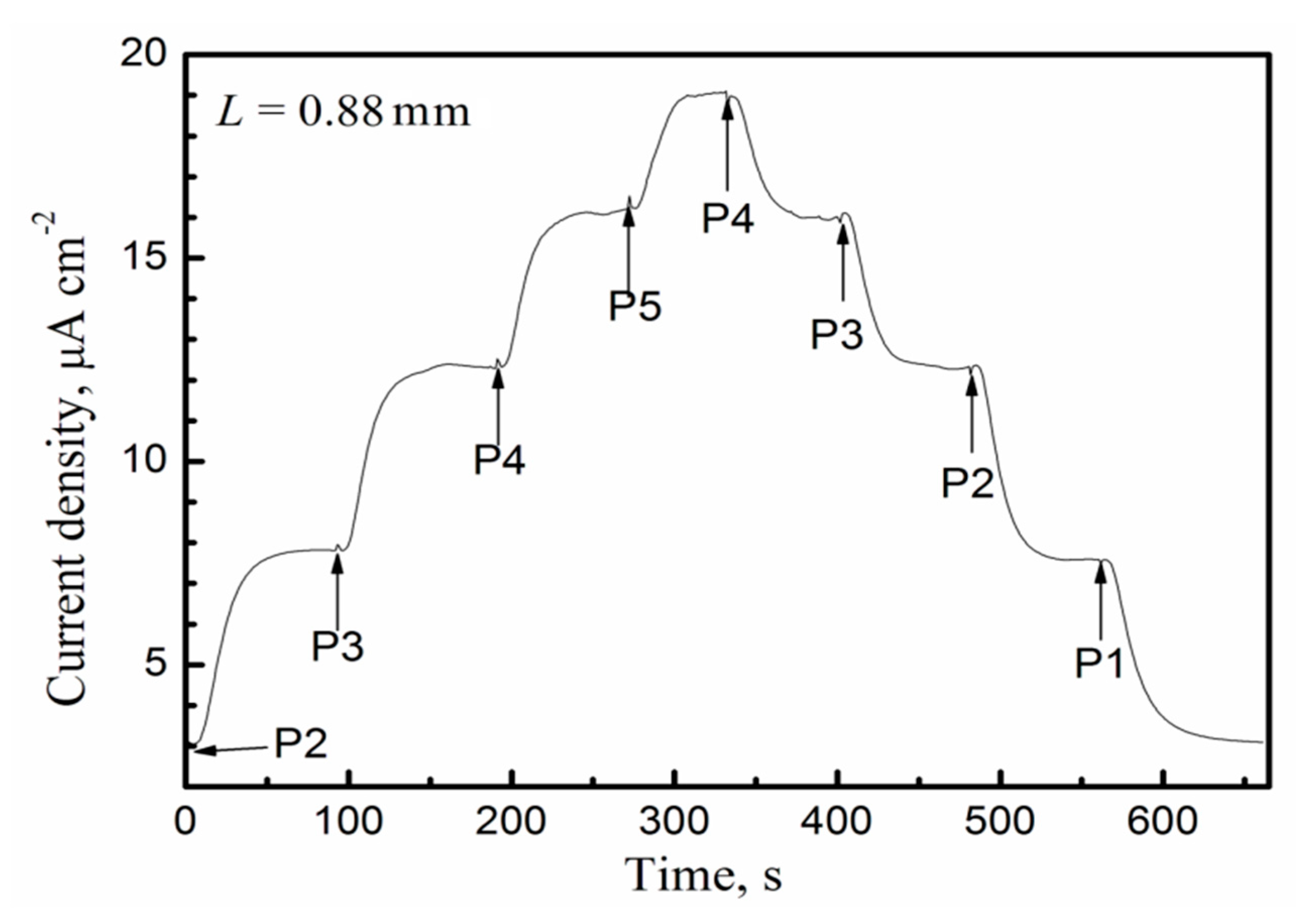
Figure 4 shows a succession of hydrogen permeation transients measured with increasing and decreasing hydrogen fugacity, by charging at various potentials in 0.1 M NaOH solution, for pure Fe hydrogen pre-charged at −1.500 VAg/AgCl in 0.1 M NaOH solution for 48 h to achieve steady state surface conditions on the input side. Note that the duration of a permeation transient was about 100 s, and was much shorter than the time required to condition the input surface to quasi steady-state. The pure Fe was annealed low interstitial steel
Each permeation curve is fitted to the whole of the theoretical curve to determine the best-fit value of the effective diffusion coefficient, Deff, for that transient. The theoretical curve for a diffusion transient is given by [4,5,15,18,19,20,22,123,136,137]:
where in is the normalized permeation current density (which varies between 0 and 1), is the initial permeation current density (or the steady state current density of the prior transient for a series of transients), is the steady state current density, L is the membrane thickness, D is the effective diffusion coefficient, Deff, and t is the time.
Figure 5 shows the expected relationship between steady state permeation current density and over-potential, as expected from Equation (5).
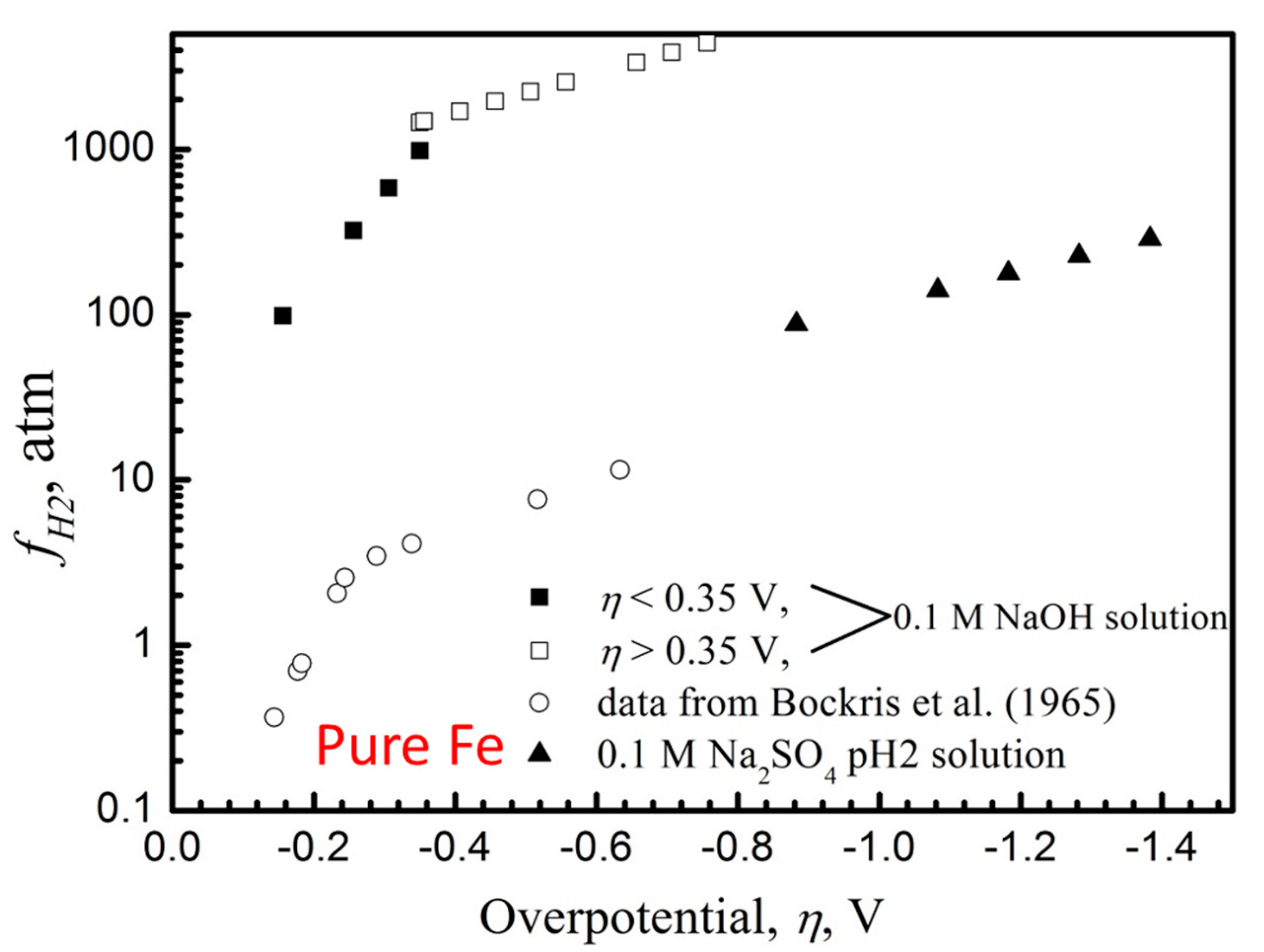
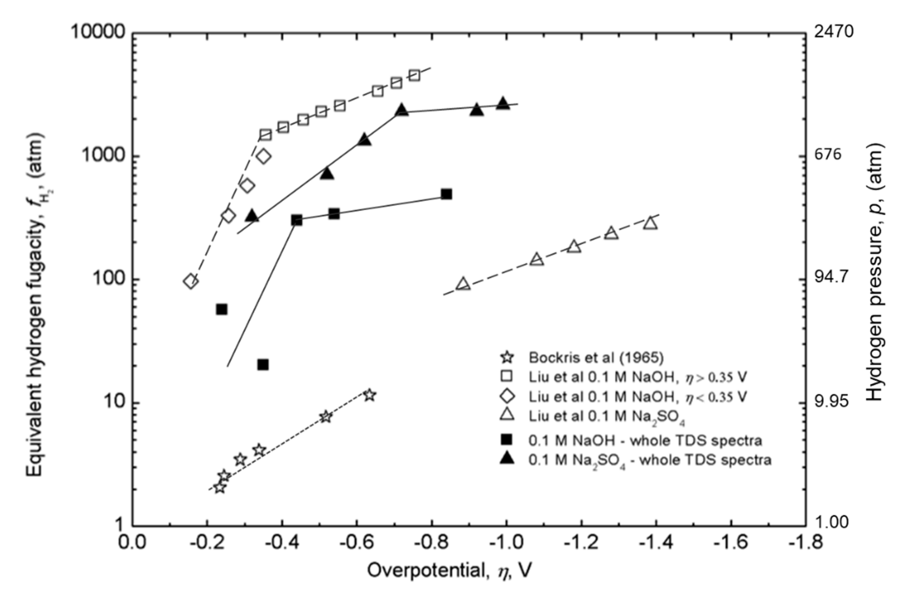
Figure 6 provides the resultant plot of equivalent hydrogen fugacity with charging over-potential for pure iron from our work [4], compared with an evaluation of the same relationship from the prior data of Bockris et al. [138], for whom the fugacity values are much lower because they carried out no preconditioning of the specimen. Key points:
- Preconditioning makes a large difference.
- The solution used for cathodic charging makes a large difference.
Thus Figure 6 provides for pure Fe the required relationship between equivalent hydrogen fugacity and over potential during cathodic charging. However, additional information is required to determine this relationship for the steels of interest in Table 1; that is the value of the Sieverts’ constant, S, was not known for these steels. This relationship for equivalent hydrogen fugacity for 3.5NiCrMoV steel is developed in the next section.
2.2. Thermal Desorption Spectroscopy
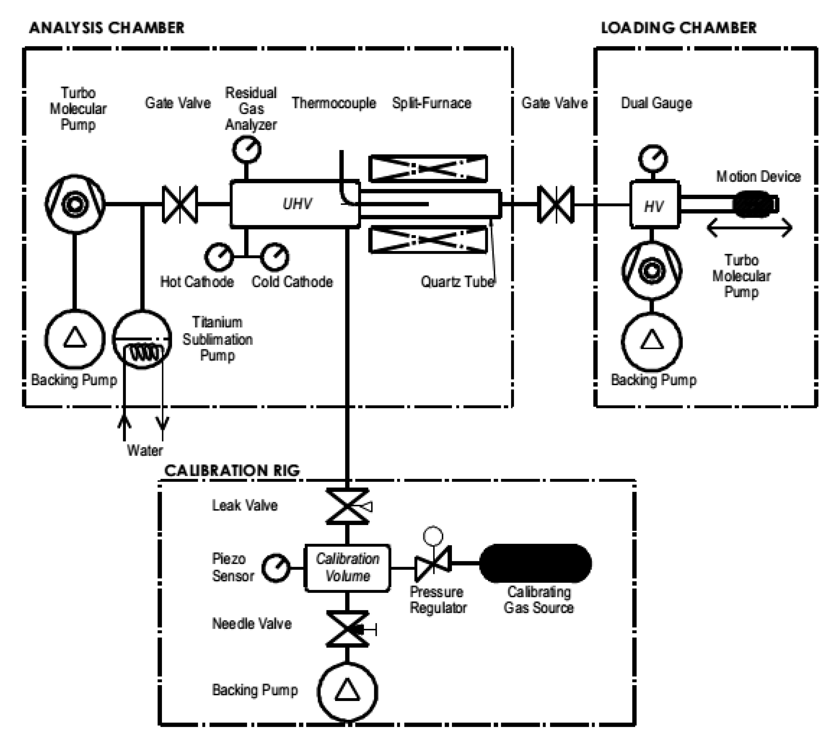
The TDS was used to measure and characterize the amount of hydrogen in the 3.5NiCrMoV steel for different charging conditions. The TDS apparatus used in this study was custom-designed at Griffith University and is designated as TDS-GU. Figure 7 provides a schematic of the new TDS-GU [9].
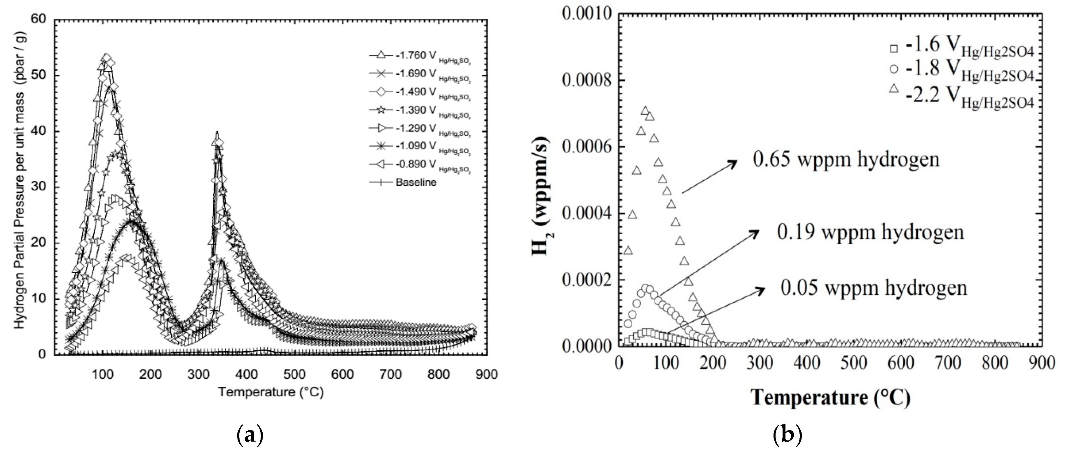
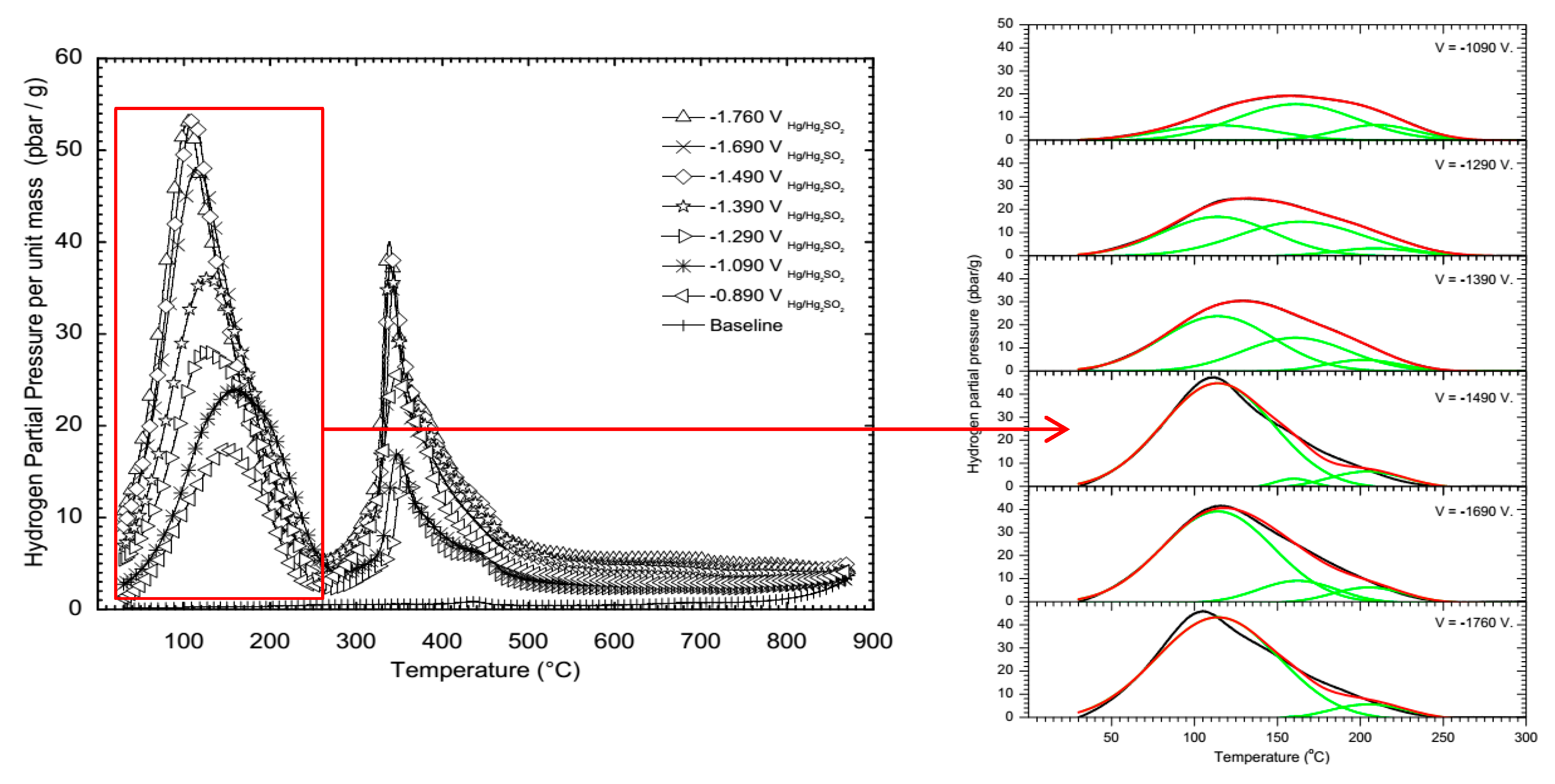
Figure 8a presents the TDS-GU spectra for 3.5NiCrMoV specimens electrochemically charged at different potentials in 0.1 M Na2SO4 solution at 25 °C for 24 h [10]. This has two composite peaks. The composite hydrogen peak at temperatures between room temperature and 250 °C is attributed to hydrogen. The composite peak above 250 °C is an experimental artefact, attributed to hydrogen from water at the specimen surface being catalytically reduced to hydrogen by the steel surface, because (i) similar peaks were measured for specimens after cathodic charging and after gaseous charging, for which in both cases there was exposure to lab air, (ii) similar peaks were measured for specimens without hydrogen, after exposure of the specimens to lab air, (iii) no peaks were measured in the TDS spectrum measured by Verbreken in Ghent using a commercial TDS (designated TDS-C) as indicated in Figure 8b [10].
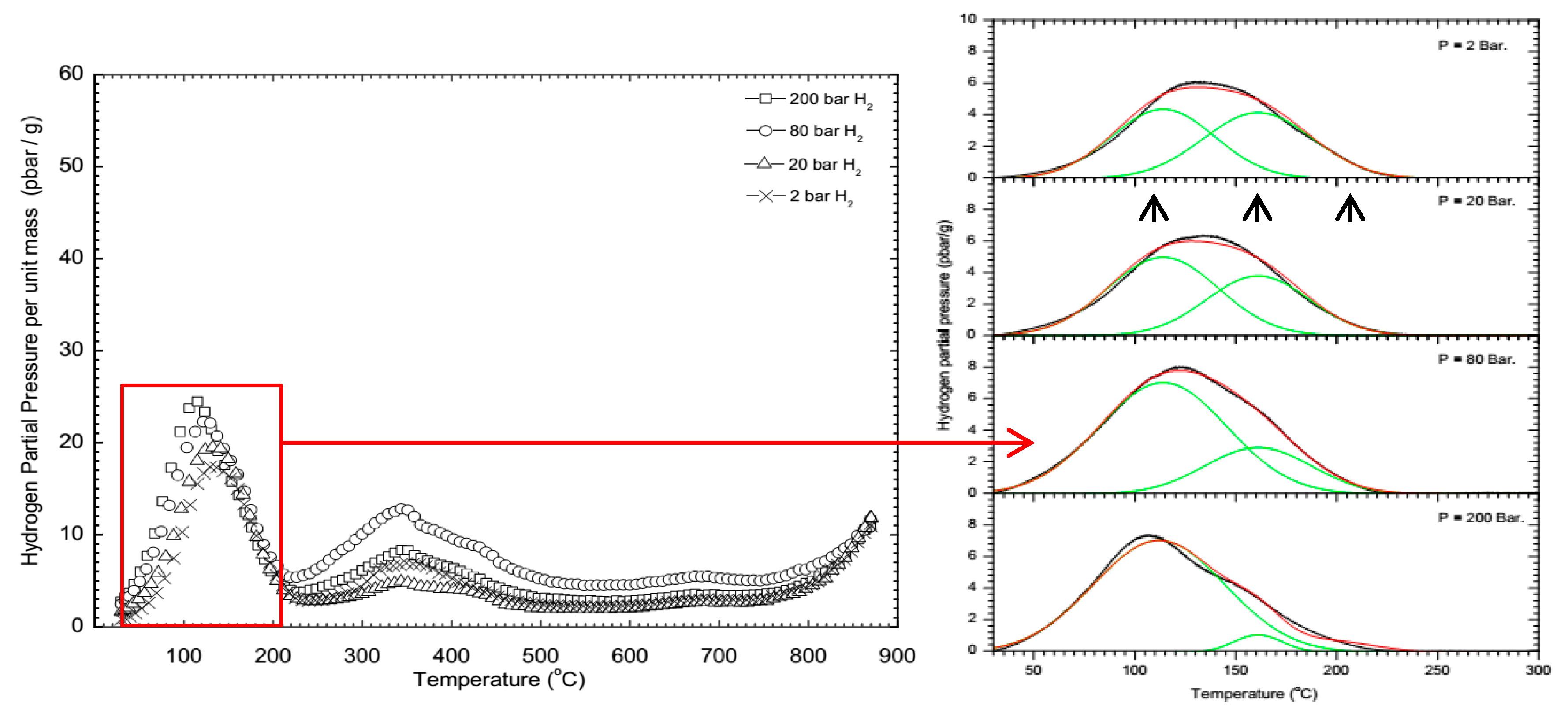
Figure 9 and Figure 10 [10] present the deconvolution of composite peak below 250 °C of the TDS-GU spectra for 3.5NiCrMoV specimens electrochemically charged at different potentials in 0.1 M Na2SO4 solution at 25 °C for 24 h and in gaseous hydrogen at the stated pressure for 24 h, into peaks at 114 °C, 160 °C and 210 °C. To a first approximation, the peak height of the 114 °C peak increased with hydrogen fugacity, whereas the peak heights of the other peaks remained constant. This was consistent with the higher temperature peaks representing deeper hydrogen traps which were essentially filled under these experimental conditions, whereas the 114 °C peak represent the hydrogen traps that were filled progressively under these experimental conditions.
The total hydrogen in each specimen was evaluated by correcting for the diffusion loss of hydrogen between the end of the hydrogen charging and the start of the TDS measurement [10].
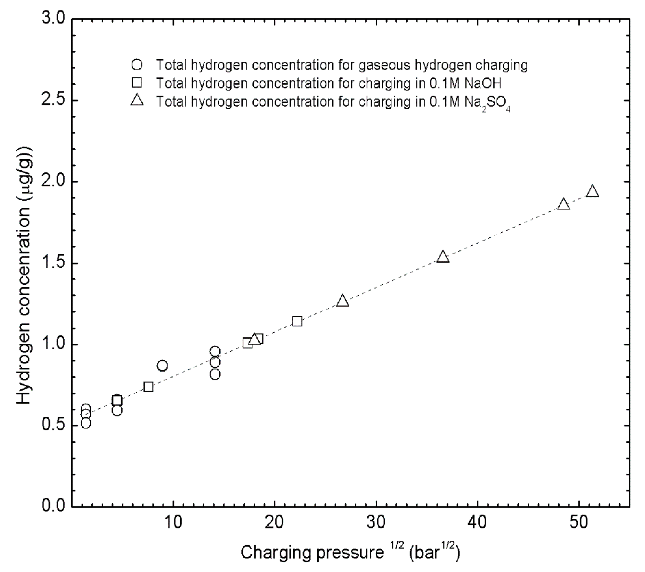
Figure 11 [10] presents the hydrogen concentration for gaseous charged specimens, which established the trend line as a function of square root of charging pressure according to Sieverts’ Law. The hydrogen concentration of the cathodic charged specimens were plotted on this line to establish their equivalent hydrogen charging pressure.
Figure 12 [10] presents the equivalent hydrogen fugacity for the 3.5NiCrMoV steel as a function of cathodic charging overpotential (full data points) compared with pure Fe (open symbols). In addition, given on the right hand axis is the hydrogen pressure [139,140]. This represents the required relationship for the hydrogen fugacity for various electrochemical charging conditions. However, the development of this relationship has identified an unexpected relationship, in Figure 11, between the hydrogen concentration and hydrogen pressure. This relationship is analyzed in the next section.
2.3. Sieverts’ Law
The positive intercept for Sieverts’ Law in Figure 11 can be understood in terms of the already filled traps as demonstrated by the TDS data in Figure 9 and Figure 10, as follows [10].
The chemical potential of hydrogen, μ, in the metal is set by the external hydrogen pressure, p.
Only one H atom can occupy a site, so Firmi-Dirac statistics is used to distribute NH H atoms among Ns sites, of which Nt are traps, so that
where εs is the energy of a Ns site, εb is the energy of a trap site.
When p is small, the traps fill preferentially, so the first term is small, so that rearranging (8) using the second terms gives
which is the typical Sieverts’ Law expression.
When the pressure increases sufficiently that the traps are filled, the second term approaches Nt/Ns, and rearranging (8) gives
which indicates that the positive intercept in Figure 11 is a measure of the amount of hydrogen in deep traps.
Furthermore, since hydrogen trapping is expected for hydrogen in steels, Figure 11 and Equation (10) illustrate what should be the typical relationship between hydrogen concentration and hydrogen pressure for steels. Moreover, this relationship should be of general applicability for all metals that exhibit hydrogen trapping.
3. H Influence—Static Strength
Now that we understand how to characterize the hydrogen introduced by cathodic hydrogen charging, the tools exist for a rigorous evaluation of the influence of hydrogen on the mechanical properties of the steels in Table 1. This section describes how hydrogen influences the strength, ductility and fracture of these steels.
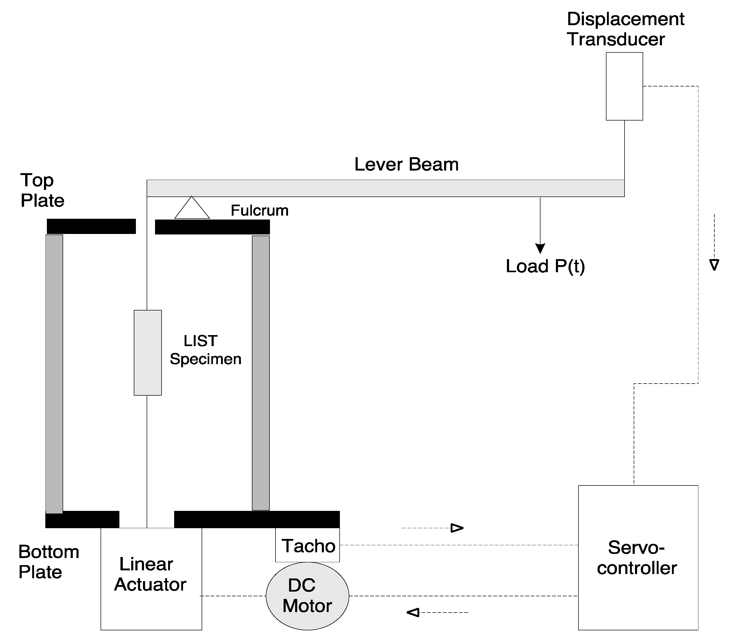
Figure 13 [2,3,93] presents the Linearly Increasing Stress Test (LIST). The specimen is located in the appropriate environment in the loading train on the left hand side of the lever beam. The Load (a known weight) is moved away from the fulcrum at a constant rate by means of a lead screw and a synchronous motor As a result, the specimen is subjected to a linearly increasing (engineering) stress until fracture. In such a load controlled test, a ductile specimen necks and fractures when the applied stress reaches at the ultimate tensile strength. At that moment the specimen becomes mechanically unstable.
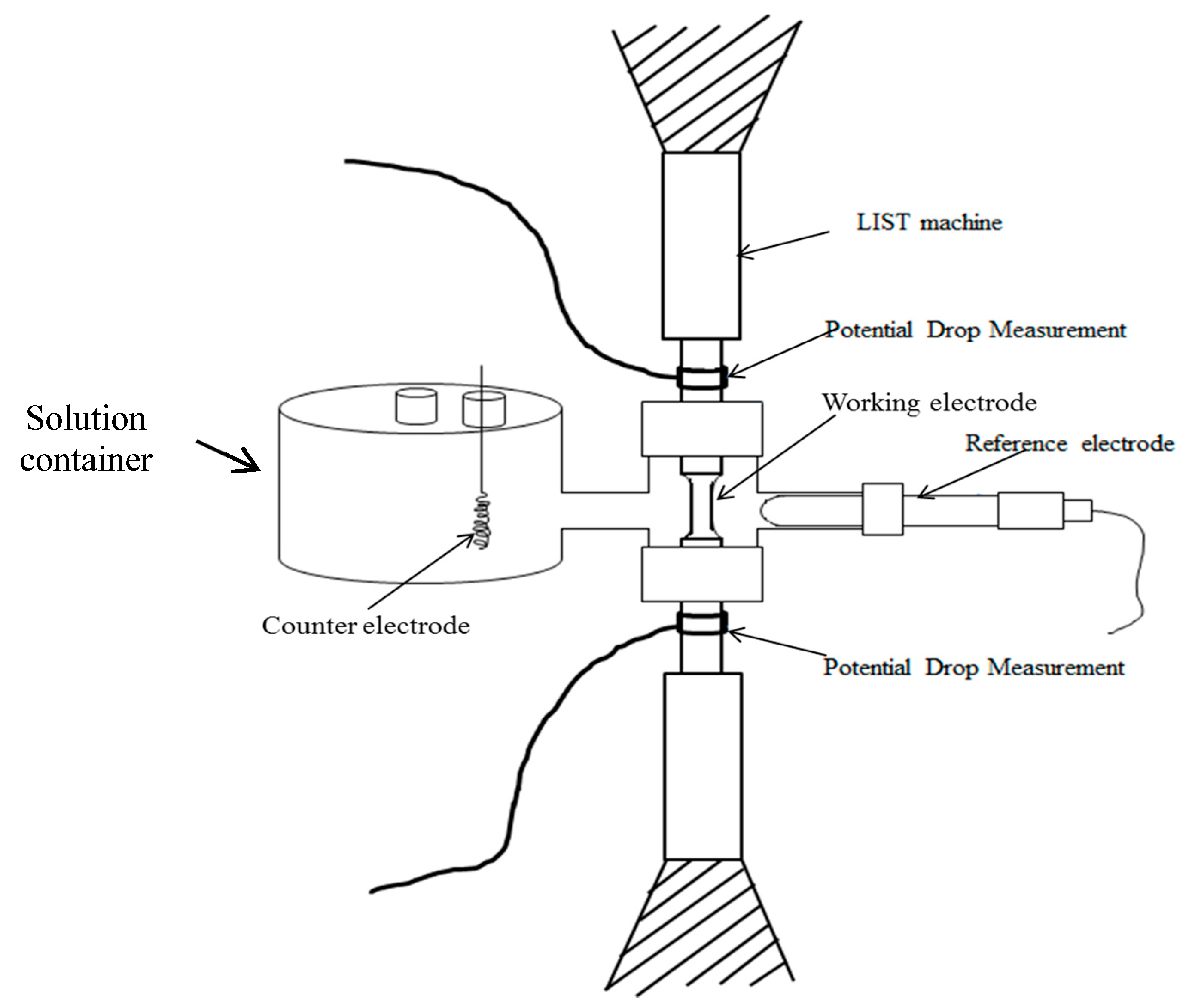
Figure 14 [2,3] presents a schematic of the hydrogen-charging cell. Figure 12 provides the relationship between the applied over-potential during the cathodic charging and the equivalent hydrogen fugacity, and the associated hydrogen pressure. During each experiment, potential drop data was measured.
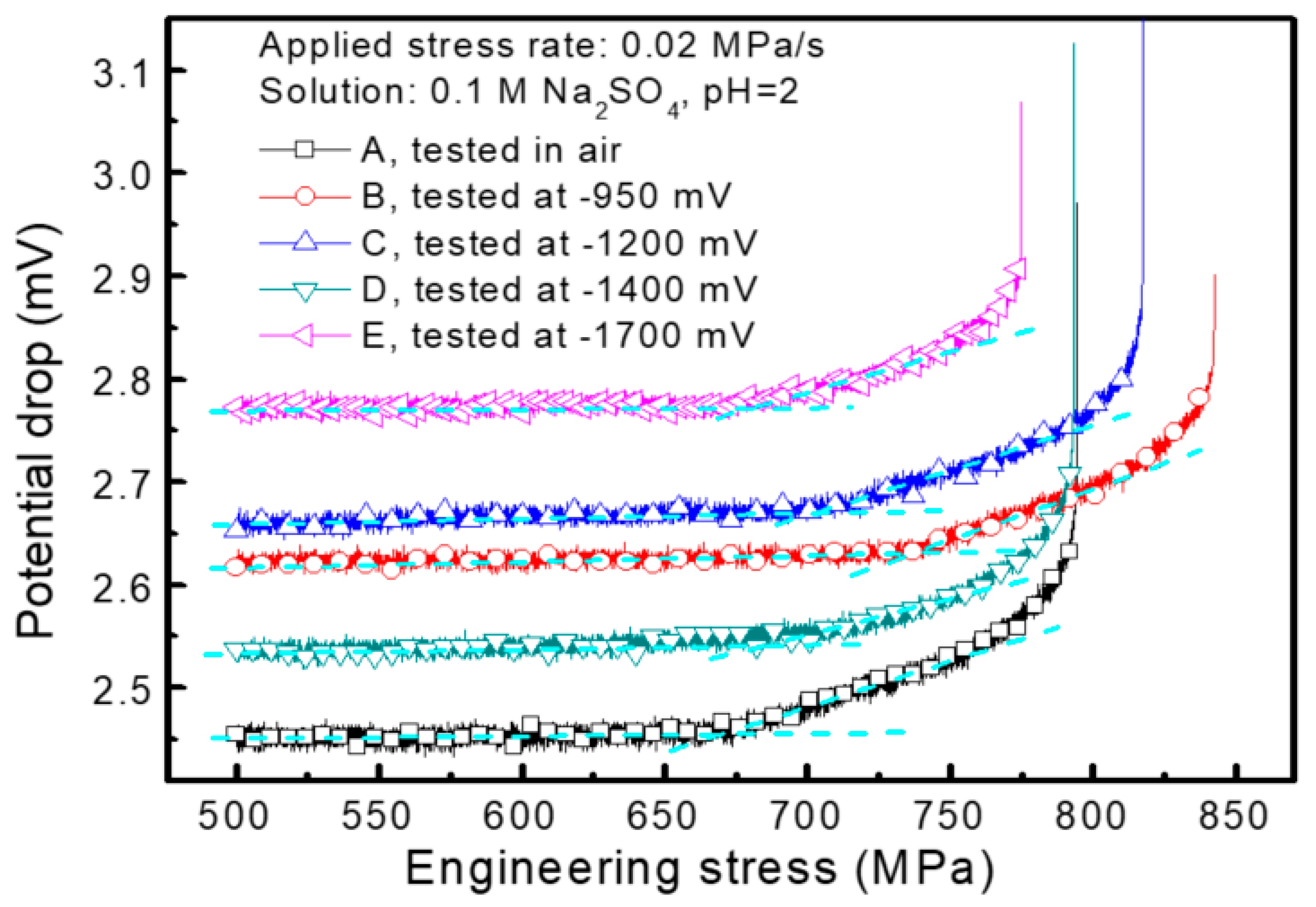
Figure 15 [2,3] presents the potential drop data, for tests in air and with increasingly negative applied potential, which correspond to rapidly increasing hydrogen fugacity, see Figure 12. The potential drop is plotted against applied engineering stress. The potential drop can be considered as the specimen electrical resistance. The potential drop initially increases linearly with increasing stress, as the specimen increases in length and decreases in diameter. There is a more rapid increase after the stress exceeds the yield stress, so that the yield stress can be measured. Similarly, the ultimate tensile strength can be measured from the load at fracture.
There was no change in the yield stress and no change in the ultimate tensile strength for the conditions depicted in Figure 15 as documented in Table 2.
This indicated that hydrogen had no influence on the mechanical properties of the 3.5NiCrMoV steel up to the equivalent hydrogen pressures associated with the cathodic charging conditions indicated in Figure 15 and Table 2.
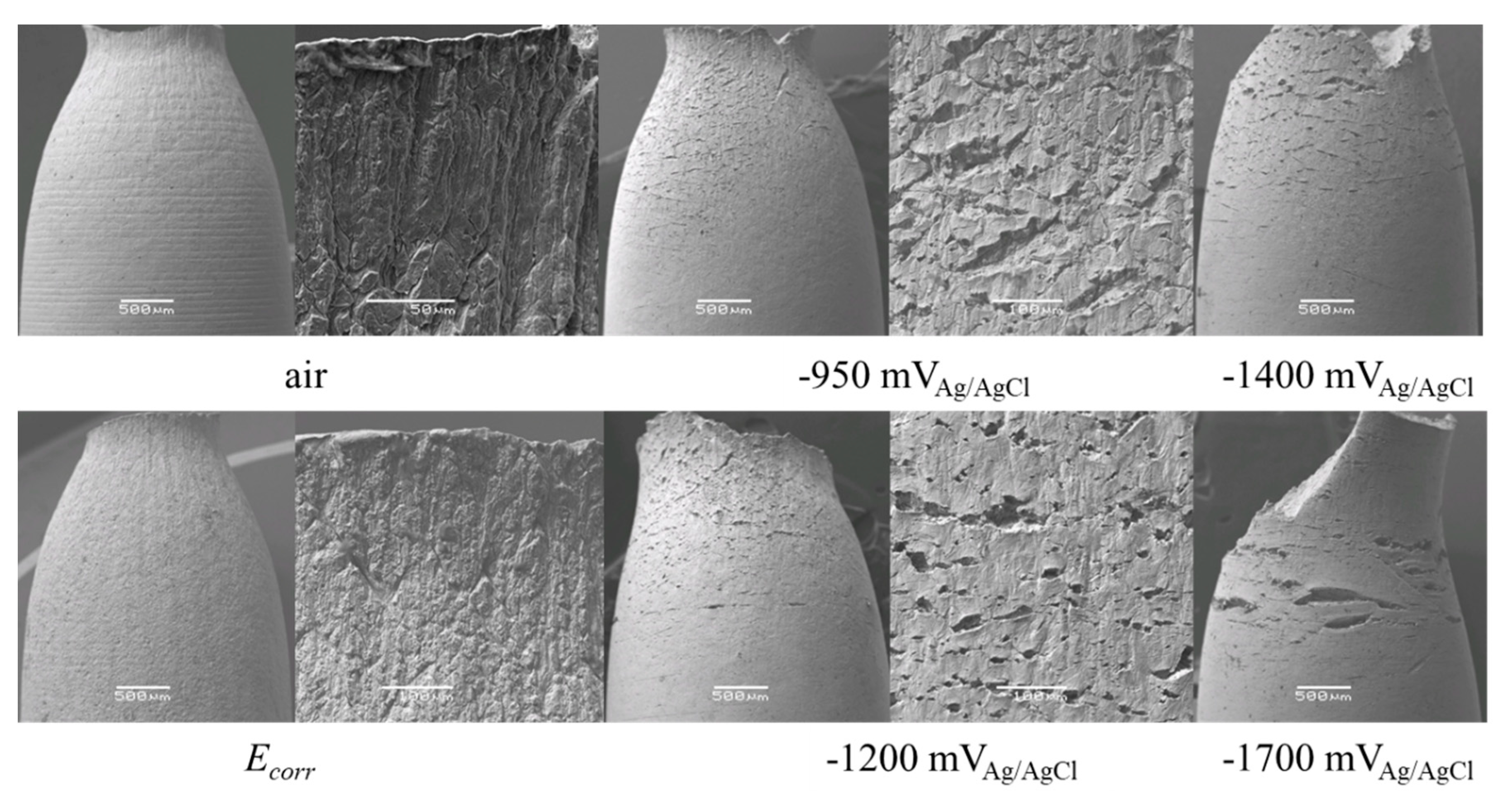
Figure 16 [2,3] presents the appearance of the LIST specimens for 3.5NiCrMoV steel tested in air, or at the free corrosion potential, or for cathodic hydrogen charging at the stated potentials in 0.1 M Na2SO4 pH 2. Shown are over-views of the side of the specimen and magnified views of the specimen surface close to the final fracture. Clearly shown is that each specimen necked. This indicates that the fractures occurred when the applied stress reached the ultimate tensile strength of the specimen and the specimen became mechanically unstable, necked and fractured. There were surface fractures in the necked region of hydrogen charged specimens, and only in the necked region of these specimens.
There was no sub-critical crack growth evidenced by the fact that there were no cracks in the gauge section away from the necked regions in any of the specimens.
These surface fractures due to hydrogen occurred during the final fracture, when the specimen was mechanically unstable.
Figure 17 presents the typical appearance of 3.5NiCrMoV steel LIST specimen tested with cathodic hydrogen charging at −950 mVAg/AgCl in 0.1 M Na2SO4 pH 2. Shown are the over-view of the specimen fracture and the indicated magnified fracture views. Regions A correspond to the hydrogen fractures that were visible on the specimen sides in Figure 16. In this case, there were brittle fractures initiated by hydrogen, or DHF: Decohesive hydrogen fracture, which initiated the final fracture of the specimen.
Regions B and C were essentially identical. They showed largely ductile micro-void dimple rupture, within which there were isolated brittle features, the most obvious of which were the fisheyes illustrated at greater magnification in the two bottom micrographs. This fractography indicated that two micro-mechanisms of fracture competed during the final fracture. There were the fisheyes, which initiated at a central region, typically at an inclusion, and fractured in a radial direction, until they encountered a fracturing region undergoing ductile micro-void fracture. Each fisheye was surrounded by such micro-void coalescence (MVC) fracture. This corresponds to MF: mixed fracture, wherein a hydrogen microfracture mechanism (that producing the fisheyes) competed with the ductile MVC fracture.
This indicates that there was no effect of hydrogen up to the yield stress. There was an influence of hydrogen on the final fracture, which occurred at the same stress as for the steels tested in air. The influence of hydrogen was on the details of the final fracture: there were some brittle hydrogen induced fracture events, which occurred simultaneously with the overall ductile fracture of the specimen. The fisheyes were associated with alumina oxide inclusion, which indicated that these features would be less for a cleaner steel. There was no subcritical crack growth.
There was essentially no influence of hydrogen on ductility for the hydrogen conditions studied.
4. H Influence—Fatigue
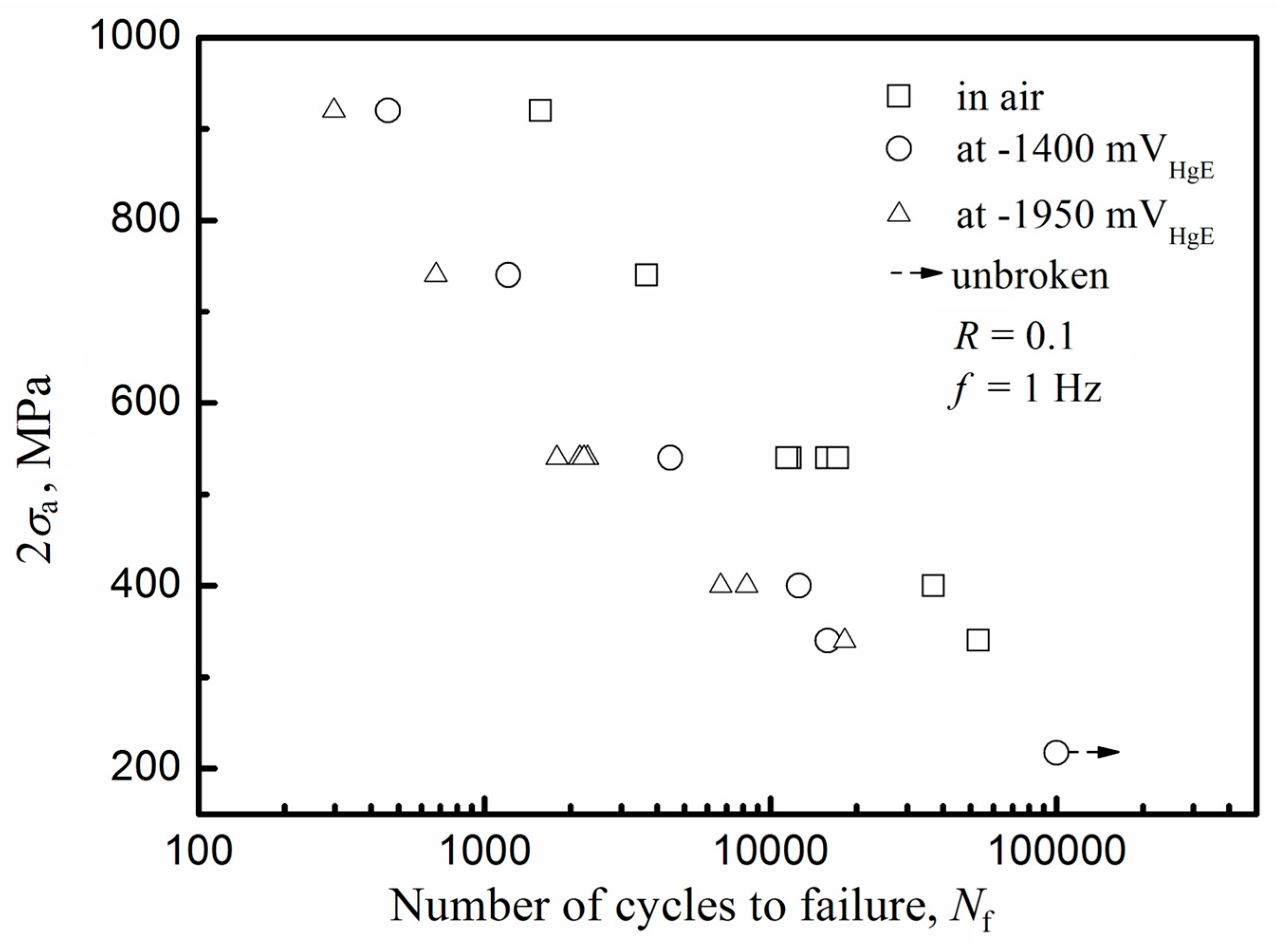
Because there was an influence of hydrogen on the final mixed fracture, it was not unexpected that there would be an influence of hydrogen on the fatigue properties. These are analyzed in this section. Liu and Atrens [8] studied the low cycle fatigue (LCF) of 3.5NiCrMoV in air and with hydrogen charging in the acidified pH 2 0.1 M Na2SO4 solution. Figure 18 presents the fatigue S-N diagram (stress amplitude versus cycles to failure) for 3.5NiCrMoV, tested as a notched specimen, in air and with cathodic hydrogen charging at the stated potentials in 0.1 M Na2SO4 pH 2. At applied stress amplitudes above the threshold, fatigue initiation occurred at a lower number of cycles with increasing hydrogen fugacity and increasing stress amplitude. This was caused by a decrease in the fatigue initiation period and by an increase in the crack growth rate. In the presence of hydrogen, there was flat transgranular fracture with vague striations with some intergranular fracture at lower stresses. Mechanical overload occurred when the fatigue crack reached the critical length. There was no significant influence of hydrogen on the final fracture.
Liu [12] found that hydrogen accelerated the fatigue crack growth of 3.5NiCrMoV, by a small amount for a significant amount of hydrogen, and a similar amount for a much higher amount of hydrogen. The acceleration was small for the stress ration R = 0.1 and larger for R = 0.8.
5. Discussion
Thus using permeation experiments and TDS characterization of the hydrogen in these steels after cathodic hydrogen charging, it was possible to determine the relationship between the equivalent hydrogen fugacity and the overpotential during cathodic hydrogen charging. On this base, it was possible to study the influence of hydrogen on the static and dynamic strength of these steels under conditions of high hydrogen fugacity, which allows evaluation of the hydrogen influence under hydrogen fugacity values appropriate to service conditions. In this regard, the LIST approach provided particularly effective in understanding the influence of hydrogen on the mechanical properties, and in understanding the influence of hydrogen on the fracture behavior.
6. Conclusions
The influence of hydrogen on the mechanical properties of four medium-strength, commercial, quenched-and-temped steels has been studied using the linearly increasing stress test (LIST) combined with cathodic hydrogen charging.
- The relationship was established between the hydrogen charging overpotential and the equivalent hydrogen pressure during cathodic hydrogen charging though the use of electrochemical permeation experiments and thermal desorption spectroscopy.
- This allows evaluation of the influence of hydrogen on the static and dynamic strength of these steels under hydrogen fugacity values appropriate to service conditions.
- The cathodic hydrogen charging conditions were equivalent to testing in gaseous hydrogen at fugacities of over a thousand bar.
- Under these hydrogen charging conditions, there was no effect of hydrogen up to the yield stress. There was an influence of hydrogen on the final fracture, which occurred at the same stress as for the steels tested in air.
- The influence of hydrogen was on the details of the final fracture: there were some brittle hydrogen induced fracture events, which occurred simultaneously with the overall ductile fracture of the specimen. In some cases, brittle fractures initiated by hydrogen, or DHF: Decohesive hydrogen fracture, initiated the final fracture of the specimen.
- The fisheyes were associated with alumina oxide inclusion, which indicated that these features would be less for a cleaner steel.
- Each fisheye was surrounded by such micro-void coalescence (MVC) fracture. This corresponds to MF: Mixed fracture, wherein a hydrogen microfracture mechanism (i.e., that producing the fisheyes) competed with the ductile MVC fracture.
- There was no subcritical crack growth. There was essentially no influence of hydrogen on ductility for the hydrogen conditions studied.
- At applied stress amplitudes above the threshold, fatigue initiation, for low cycle fatigue, occurred at a lower number of cycles with increasing hydrogen fugacity and increasing stress amplitude. This was caused by a decrease in the fatigue initiation period and by an increase in the crack growth rate. In the presence of hydrogen, there was flat transgranular fracture with vague striations with some intergranular fracture at lower stresses. Mechanical overload occurred when the fatigue crack reached the critical length. There was no significant influence of hydrogen on the final fracture.
Author Contributions
All authors made a substantial contribution to this research. A.A., Q.L. (Qian Liu), C.T., E.G., B.I., J.V. and Q.L. (Qinglong Liu) conceived and designed experiments; Q.L. (Qian Liu), C.T., J.V. and Q.L. (Qinglong Liu) carried out the experiments; A.A., Q.L. (Qian Liu), C.T., E.G., B.I., J.V. and Q.L. (Qinglong Liu) analyzed data; A.A., Q.L. (Qian Liu), C.T., E.G., B.I., J.V. and Q.L. (Qinglong Liu) wrote the paper.
Acknowledgments
This work is supported by an Australian Research Council linkage grant (LP0990522) and General Electric (Switzerland) GmbH, CH-5242 Birr, Switzerland. Thank you to Australian Microscopy and Microanalysis Research Facilities. Atrens wishes to express his thanks to Frédéric Christien, Krzysztof Wolski, David Delafosse, Milos Djukic, Alexander Henschel and Klaus Rau for stimulating discussions, and for special studies program support to the Ecole Nationale Supérieure de Mines de Saint-Etienne, Saint-Étienne, France.
Conflicts of Interest
The authors declare no conflict of interest.
References
- Liu, Q.; Atrens, A. A critical review of the influence of hydrogen on the mechanical properties of medium strength steels. Corros. Rev. 2013, 31, 85–104. [Google Scholar] [CrossRef]
- Liu, Q.; Irwanto, B.; Atrens, A. The influence of hydrogen on 3.5NiCrMoV steel studied using the linearly increasing stress test. Corros. Sci. 2013, 67, 193–203. [Google Scholar] [CrossRef]
- Liu, Q.; Irwanto, B.; Atrens, A. Influence of hydrogen on the mechanical properties of some medium strength Ni-Cr-Mo steels. Mater. Sci. Eng. A 2014, 617, 200–210. [Google Scholar] [CrossRef]
- Liu, Q.; Atrens, A.D.; Shi, Z.; Verbeken, K.; Atrens, A. Determination of the hydrogen fugacity during electrolytic charging of steel. Corros. Sci. 2014, 87, 239–258. [Google Scholar] [CrossRef] [Green Version]
- Liu, Q.; Atrens, A. Reversible hydrogen trapping in a 3.5NiCrMoV medium strength steel. Corros. Sci. 2015, 96, 112–120. [Google Scholar] [CrossRef]
- Liu, Q.; Irwanto, B.; Atrens, A. Steels for the hydrogen economy. In Proceedings of the 5th Baosteel Biennial Academic Conference (BAC2013), Shanghai, China, 4–6 June 2013. [Google Scholar]
- Liu, Q.; Irwanto, B.; Atrens, A. The tensile properties of NiCrMo1 steel under conditions of hydrogen charging studied using the linearly increasing stress test. In Proceedings of the ICF13 13th International Conference on Fracture, Beijing, China, 16–21 June 2013; Yu, S., Feng, X.-Q., Eds.; Science Literature Publishing House: Beijing, China, 2013; Volume 2, pp. 1396–1405. [Google Scholar]
- Liu, Q.; Atrens, A. The influence of hydrogen on the low cycle fatigue behavior of medium strength 3.5NiCrMoV steel studied using notched specimens. Adv. Eng. Mater. 2018, 20, 1700680. [Google Scholar] [CrossRef]
- Tapia-Bastidas, C.V.; Atrens, A.; Gray, E.M. Thermal desorption spectrometer for measuring ppm concentrations of trapped hydrogen. Int. J. Hydrog. Energy 2018, 43, 7600–7617. [Google Scholar] [CrossRef]
- Venezuela, J.; Tapia-Bastidas, C.; Zhou, Q.; Depover, T.; Verbeken, K.; Gray, E.; Liu, Q.; Liu, Q.; Zhang, M.; Atrens, A. Determination of the equivalent hydrogen fugacity during electrochemical charging of 3.5NiCrMoV steel. Corros. Sci. 2018, 132, 90–106. [Google Scholar] [CrossRef]
- Atrens, A.; Venezuela, J.; Liu, Q.; Zhou, Q.; Verbeken, K.; Tapia-Bastidas, C.; Gray, E.; Christien, F.; Wolski, K. Electrochemical and mechanical aspects of hydrogen embrittlement evaluation of martensitic steels. In Encyclopedia of Interfacial Chemistry: Surface Science and Electrochemistry; Wandel, K., Ed.; Elsevier: New York, NY, USA, 2018; Volume 6, pp. 201–225. [Google Scholar]
- Liu, Q. Influence of Hydrogen on Metallic Components for Clean Energy. Ph.D. Thesis, The University of Queensland, Brisbane, Australia, 2015. [Google Scholar]
- Tapia-Bastidas, C.V. The Design, Construction and Implementation of a Novel State-of-the-Art Thermal Desorption Spectrometer for the Study of Hydrogen Embrittlement of Medium Strength Steels. Ph.D. Thesis, Griffith University, Nathan, Australia, 2016. [Google Scholar]
- Venezuela, J.; Liu, Q.; Zhang, M.; Zhou, Q.; Atrens, A. A review of hydrogen embrittlement of martensitic advanced high strength steels. Corros. Rev. 2016, 34, 153–186. [Google Scholar] [CrossRef]
- Liu, Q.; Zhou, Q.; Venezuela, J.; Zhang, M.-X.; Wang, J.Q.; Atrens, A. A review of the influence of hydrogen on the mechanical properties of DP, TRIP and TWIP advanced high strength steels for auto construction. Corros. Rev. 2016, 34, 127–152. [Google Scholar] [CrossRef]
- Venezuela, J.; Blanch, J.; Zulkiply, A.; Liu, Q.; Zhou, Q.; Zhang, M.; Atrens, A. Further study of the hydrogen embrittlement of martensitic advanced high strength steel in simulated auto service conditions. Corros. Sci. 2018, 135, 120–135. [Google Scholar] [CrossRef]
- Liu, Q.; Zhou, Q.; Venezuela, J.; Zhang, M.; Atrens, A. The role of microstructure on the influence of hydrogen in some advanced high strength steels. Mater. Sci. Eng. A 2018, 715, 370–378. [Google Scholar] [CrossRef]
- Liu, Q.; Gray, E.; Venezuela, J.; Zhou, Q.; Tapia-Bastidas, C.; Zhang, M.; Atrens, A. Equivalent hydrogen fugacity during electrochemical charging of 980DP steel determined by thermal desorption spectroscopy. Adv. Eng. Mater. 2018, 20, 1700469. [Google Scholar] [CrossRef]
- Venezuela, J.; Zhou, Q.; Liu, Q.; Zhang, M.; Atrens, A. Hydrogen trapping in some automotive martensitic advanced high-strength steels. Adv. Eng. Mater. 2018, 20, 1700468. [Google Scholar] [CrossRef]
- Venezuela, J.; Gray, E.; Liu, Q.; Zhou, Q.; Tapia-Bastidas, C.; Zhang, M.; Atrens, A. Equivalent hydrogen fugacity during electrochemical charging of some martensitic advanced high-strength steels. Corros. Sci. 2017, 127, 45–58. [Google Scholar] [CrossRef]
- Liu, Q.; Zhou, Q.; Venezuela, J.; Zhang, M.; Atrens, A. Hydrogen influence on some advanced high-strength steels. Corros. Sci. 2017, 125, 114–138. [Google Scholar] [CrossRef]
- Liu, Q.; Zhou, Q.; Venezuela, J.; Zhang, M.; Atrens, A. Hydrogen concentration in dual phase (DP) and quenched and partitioned (Q&P) advanced high strength steels (AHSS) under simulated service conditions compared with cathodic charging conditions. Adv. Eng. Mater. 2016, 18, 1588–1599. [Google Scholar]
- Liu, Q.; Venezuela, J.; Zhang, M.; Zhou, Q.; Atrens, A. Hydrogen trapping in some advanced high strength steels. Corros. Sci. 2016, 111, 770–785. [Google Scholar] [CrossRef] [Green Version]
- Venezuela, J.; Zhou, Q.; Liu, Q.; Zhang, M.; Atrens, A. Influence of hydrogen on the mechanical and fracture properties of some martensitic advanced high strength steels in simulated service conditions. Corros. Sci. 2016, 111, 602–624. [Google Scholar] [CrossRef]
- Venezuela, J.; Liu, Q.; Zhang, M.X.; Zhou, Q.; Atrens, A. The influence of hydrogen on the mechanical and fracture properties of some advanced high strength steels studied using the linearly increasing stress test. Corros. Sci. 2015, 99, 98–117. [Google Scholar] [CrossRef]
- Husby, H.; Iannuzzi, M.; Kappes, M.; Barnoush, A. Effect of nickel on hydrogen permeation in ferritic/pearlitic low alloy steels. Int. J. Hydrog. Energy 2018, 43, 3845–3861. [Google Scholar] [CrossRef]
- Rogne, B.R.S.; Kheradmand, N.; Deng, Y.; Barnoush, A. In situ micromechanical testing in environmental scanning electron microscope: A new insight into hydrogen-assisted cracking. Acta Mater. 2018, 144, 257–268. [Google Scholar] [CrossRef]
- Deng, Y.; Barnoush, A. Hydrogen embrittlement revealed via novel in situ fracture experiments using notched micro-cantilever specimens. Acta Mater. 2018, 142, 236–247. [Google Scholar] [CrossRef]
- Hajilou, T.; Deng, Y.; Rogne, B.R.; Kheradmand, N.; Barnoush, A. In situ electrochemical microcantilever bending test: A new insight into hydrogen enhanced cracking. Scr. Mater. 2017, 132, 12–21. [Google Scholar] [CrossRef]
- Djukic, M.B.; Zeravcic, V.S.; Bakic, G.M.; Sedmak, A.; Rajicic, B. Hydrogen damage of steels: A case study and hydrogen embrittlement model. Eng. Fail. Anal. 2015, 58, 485–498. [Google Scholar] [CrossRef]
- Djuki, M.B.; Bakic, G.M.; Zeravcic, V.S.; Rajicic, B.; Seedmak, A.; Mitrovic, R.; Miskovic, Z. Towards a unified and practical industrial model for prediction of hydrogen embrittlement and damage in steels. Procedia Struct. Integr. 2016, 2, 604–611. [Google Scholar] [CrossRef]
- Djukic, M.B.; Zeravcic, V.S.; Bakic, G.; Sedmak, A.; Rajicic, B. Hydrogen embrittlement of low carbon structural steel. Procedia Mater. Sci. 2014, 3, 1167–1172. [Google Scholar] [CrossRef]
- Iannuzzi, M. Environmentally assisted cracking (EAC) in oil and gas production. In Stress Corrosion Cracking; Woodhead Publishing Ltd.: Sawston, UK, 2011; pp. 570–607. [Google Scholar]
- Li, B.; Koyama, M.; Sakurada, E.; Yoshimura, N.; Ushioda, K.; Noguchi, H. Temperature dependence of transgranular fatigue crack resistance in interstitial-free steel and Fe-C steels with supersaturated carbon: Effects of dynamic strain aging and dynamic precipitation. Int. J. Fatigue 2018, 110, 1–9. [Google Scholar] [CrossRef]
- Mohammadi, A.; Koyama, M.; Gerstein, G.; Maier, H.J.; Noguchi, H. Hydrogen-assisted failure in a bimodal twinning-induced plasticity steel: Delamination events and damage evolution. Int. J. Hydrog. Energy 2018, 43, 2492–2502. [Google Scholar] [CrossRef]
- Li, B.; Koyama, M.; Hamada, S.; Noguchi, H. Threshold stress intensity factor range of a mechanically-long and microstructually-short crack perpendicular to an interface with plastic mismatch. Eng. Fract. Mech. 2017, 182, 287–302. [Google Scholar] [CrossRef]
- Yoshimura, N.; Ushioda, K.; Yonemura, M.; Koyama, M.; Tanaka, M.; Noguchi, H. Effect of the state of carbon on ductility in Fe-0.017mass%C ferritic steel. Mater. Sci. Eng. A 2017, 701, 120–128. [Google Scholar] [CrossRef]
- Koyama, M.; Onishi, Y.; Noguchi, H. Characteristics of hydrogen assisted intergranular fatigue crack growth in interstitial free steel: Role of plastic strain localization. Int. J. Fract. 2017, 206, 123–130. [Google Scholar] [CrossRef]
- Jemblie, L.; Olden, V.; Maincon, P.; Akselsen, O.M. Cohesive zone modelling of hydrogen induced cracking on the interface of clad steel pipes. Int. J. Hydrog. Energy 2017, 42, 28622–28634. [Google Scholar] [CrossRef]
- Yu, H.; Olsen, J.S.; Olden, V.; Alvaro, A.; He, J.Y.; Zhang, Z. Cohesive zone simulation of grain size and misorientation effects on hydrogen embrittlement in nickel. Eng. Fail. Anal. 2017, 81, 79–93. [Google Scholar] [CrossRef]
- Alvaro, A.; Jensen, I.; Kheradmand, N.; Løvvik, O.M.; Olden, V. Hydrogen embrittlement in nickel, visited by first principles modeling, cohesive zone simulation and nanomechanical testing. Int. J. Hydrog. Energy 2015, 40, 16892–16900. [Google Scholar] [CrossRef]
- Depover, T.; Verbeken, K. Thermal desorption spectroscopy study of the hydrogen trapping ability of W based precipitates in a Q&T matrix. Int. J. Hydrog. Energy 2018, 43, 5760–5769. [Google Scholar]
- Depover, T.; Verbeken, K. The effect of TiC on the hydrogen induced ductility loss and trapping behavior of Fe-C-Ti alloys. Corros. Sci. 2016, 112, 308–326. [Google Scholar] [CrossRef]
- Depover, T.; Verbeken, K. Evaluation of the effect of V4C3 precipitates on the hydrogen induced mechanical degradation in Fe-C-V alloys. Mater. Sci. Eng. A 2016, 675, 299–313. [Google Scholar] [CrossRef]
- Depover, T.; Verbeken, K. Evaluation of the role of Mo2C in hydrogen induced ductility loss in Q&T FeCMo alloys. Int. J. Hydrog. Energy 2016, 41, 14310–14329. [Google Scholar]
- Depover, T.; Verbeken, K. Hydrogen trapping and hydrogen induced mechanical degradation in lab cast Fe-C-Cr alloys. Mater. Sci. Eng. A 2016, 669, 134–149. [Google Scholar] [CrossRef]
- Depover, T.; Verbeken, K. Hydrogen induced mechanical degradation in tungsten alloyed steels. Mater. Charact. 2018, 136, 84–93. [Google Scholar] [CrossRef]
- Fan, Y.H.; Zhang, B.; Yi, H.L.; Hao, G.S.; Sun, Y.Y.; Wang, J.Q.; Han, E.H.; Ke, W. The role of reversed austenite in hydrogen embrittlement fracture of S41500 martensitic stainless steel. Acta Mater. 2017, 139, 188–195. [Google Scholar] [CrossRef]
- Zafra, A.; Peral, L.B.; Belzunce, J.; Rodríguez, C. Effect of hydrogen of on the tensile properties of 42CrMo4 steel quenched and tempered at different temperatures. In. J. Hydrog. Energy 2018, 43, 9068–9082. [Google Scholar] [CrossRef]
- Shin, D.H.; Lee, T.; Lee, J.; Lee, H.J.; Yoo, J.Y.; Lee, C.S. Increased resistance to hydrogen embrittlement in high-strength steels composed of granular bainite. Mater. Sci. Eng. A 2018, 700, 473–480. [Google Scholar] [CrossRef]
- García, T.E.; Arroyo, B.; Rodríguez, C.; Belzunce, F.J.; Álvarez, J.A. Small punch test methodologies for the analysis of the hydrogen embrittlement of structural steels. Theor. Appl. Fract. Mech. 2016, 86A, 89–100. [Google Scholar] [CrossRef]
- Sanchez, J.; Martin-Rengel, S.F.L.M.A.; Fullea, J.; Andrade, C.; Ruiz-Herevias, J. Measurement of hydrogen and embrittlement of high strength steels. Eng. Fail. Anal. 2016, 59, 467–477. [Google Scholar] [CrossRef]
- Ichii, K.; Koyama, M.; Tasan, C.C.; Tsuzaki, K. Comparative study of hydrogen embrittlement in stable and metastable high-entropy alloys. Scr. Mater. 2018, 150, 74–77. [Google Scholar] [CrossRef]
- Djukic, M.B.; Bakic, G.M.; Sijacki Zeravcic, V.; Sedmak, A.; Rajicic, B. Hydrogen Embrittlement of Industrial Components: Prediction, Prevention, and Models. Corrosion 2016, 72, 943–961. [Google Scholar] [CrossRef]
- Popov, B.N.; Lee, J.; Djukic, M.B. Chapter 7: Hydrogen Permeation and Hydrogen Induced Cracking. In Handbook of Environmental Degradation of Materials, 3rd ed.; Kutz, M., Ed.; Elsevier: New York, NY, USA, 2018. [Google Scholar]
- Iannuzzi, M.; Barnoush, A.; Johnsen, R. Materials and Corrosion Trends in Offshore and Subsea Oil and Gas Production. Mater. Degrad. 2017, 1, 2. [Google Scholar] [CrossRef]
- Barnoush, A.; Yang, B.; Vehoff, H. Chapter: Effect of Hydrogen and Grain Boundaries on Dislocation Nucleation and Multiplication Examined with a NI-AFM. In Advances in Solid State Physics; Springer: Berlin, Germany, 2008; Volume 47, pp. 253–269. [Google Scholar]
- Koyama, M.; Akiyama, E.; Lee, Y.-K.; Raabe, D.; Tsuzaki, K. Overview of hydrogen embrittlement in high-Mn steels. Int. J. Hydrog. Energy 2017, 42, 12706–12723. [Google Scholar] [CrossRef]
- Koyama, M.; Rohwerder, M.; Tasan, C.C.; Bashir, A.; Akiyama, E.; Takai, K.; Raabe, D.; Tsuzaki, K. Recent progress in microstructural hydrogen mapping in steels: Quantification, kinetic analysis, and multi-scale characterization. Mater. Sci. Technol. 2017, 33, 1481–1496. [Google Scholar] [CrossRef]
- Jemblie, L.; Olden, V.; Akselsen, O.M. A review of cohesive zone modelling as an approach for numerically assessing hydrogen embrittlement of steel structures. Philos. Trans. R. Soc. A 2017, 375, 20160411. [Google Scholar] [CrossRef] [PubMed] [Green Version]
- Iannuzzi, M. Chapter 15: Environmentally assisted cracking (EAC) in oil and gas production. In Stress Corrosion Cracking: Theory and Practice; Raja, V.S., Shoji, T., Eds.; Woodhead: Sawston, UK, 2011; pp. 570–607. [Google Scholar]
- Myers, S.; Baskes, M.; Birnbaum, H.; Corbett, J.; DeLeo, G.; Estreicher, S.K.; Haller, E.E.; Jena, P.; Johnson, N.M.; Kirchheim, R.; et al. Hydrogen interactions with defects in crystalline solids. Rev. Mod. Phys. 1992, 64, 559–617. [Google Scholar] [CrossRef]
- Serebrinsky, A.; Carter, E.A.; Ortiz, M. A quantum-mechanically informed continuum model of hydrogen embrittlement. J. Mech. Phys. Solids 2004, 52, 2403–2430. [Google Scholar] [CrossRef]
- Lynch, S. Hydrogen embrittlement phenomena and mechanisms. Corros. Rev. 2012, 30, 105–123. [Google Scholar] [CrossRef]
- Pundt, A.; Kirchheim, R. Hydrogen in metals: Microstructural aspects. Annu. Rev. Mater. Res. 2006, 36, 555–608. [Google Scholar] [CrossRef]
- Bhadeshia, H.K. Prevention of hydrogen embrittlement in steels. ISIJ Int. 2016, 56, 24–36. [Google Scholar] [CrossRef]
- Robertson, I.M.; Sofronis, P.; Nagao, A.; Martin, M.L.; Wang, S.; Gross, D.W.; Nygren, K.E. Hydrogen embrittlement understood. Metall. Mater. Trans. B 2015, 46, 1085–1103. [Google Scholar] [CrossRef]
- Song, J.; Curtin, W.A. Atomic mechanism and prediction of hydrogen embrittlement in iron. Nat. Mater. 2013, 12, 145–151. [Google Scholar] [CrossRef] [PubMed]
- Oriani, R.A. Award lecture-1987: Hydrogen-the versatile embrittler. Corrosion 1987, 43, 390–397. [Google Scholar] [CrossRef]
- Dadfarnia, M.; Nagao, A.; Wang, S.; Martin, M.L.; Somerday, B.P.; Sofronis, P. Recent advances on hydrogen embrittlement of structural materials. Int. J. Fract. 2015, 196, 223–243. [Google Scholar] [CrossRef]
- Nagao, A.; Dadfarnia, M.; Somerday, B.P.; Sofronis, P.; Ritchie, R.O. Hydrogen-enhanced-plasticity mediated decohesion for hydrogen-induced intergranular and “quasi-cleavage” fracture of lath martensitic steels. J. Mech. Phys. Solids 2018, 112, 403–430. [Google Scholar] [CrossRef]
- Nagao, A.; Smith, C.D.; Dadfarnia, M.; Sofronis, P.; Robertson, I.M. The role of hydrogen in hydrogen embrittlement fracture of lath martensitic steel. Acta Mater. 2012, 60, 5182–5189. [Google Scholar] [CrossRef]
- Barrera, O.; Bombac, D.; Chen, Y.; Daff, T.D.; Galindo-Nava, E.; Gong, P.; Haley, D.; Horton, R.; Katzarov, I.; Kermode, J.R.; et al. Understanding and mitigating hydrogen embrittlement of steels: A review of experimental, modelling and design progress from atomistic to continuum. J. Mater. Sci. 2018, 53, 6251–6290. [Google Scholar] [CrossRef]
- Katz, Y.; Tymiak, N.; Gerberich, W.W. Nanomechanical probes as new approaches to hydrogen/deformation interaction studies. Eng. Fract. Mech. 2001, 68, 619–646. [Google Scholar] [CrossRef]
- Nagumo, M. Hydrogen related failure of steels-a new aspect. Mater. Sci. Technol. 2004, 20, 940–950. [Google Scholar] [CrossRef]
- Ramamurthy, R.; Atrens, A. Stress Corrosion Cracking of High Strength Steels. Corros. Rev. 2013, 31, 1–31. [Google Scholar] [CrossRef]
- Ganglof, R.P.; Somerday, B.P. Gaseous Hydrogen Embrittlement of Materials in Energy Technologies; Woodhead: Sawston, UK, 2012. [Google Scholar]
- Dietzel, W.; Atrens, A.; Barnoush, A. Mechanics of modern test methods and quantitative-accelerated testing for hydrogen embrittlement. In Gaseous Hydrogen Embrittlement of Materials in Energy Technologies; Ganglof, R.P., Somerday, B.P., Eds.; Woodhead: Sawston, UK, 2012; Chapter 8; pp. 237–273. [Google Scholar]
- Villalba, E.; Atrens, A. Hydrogen Embrittlement and Rock Bolt Stress Corrosion Cracking. Eng. Fail. Anal. 2009, 16, 164–175. [Google Scholar] [CrossRef]
- Villalba, E.; Atrens, A. Metallurgical Aspects of Rock Bolt Stress Corrosion Cracking. Mater. Sci. Eng. A 2008, 491, 8–18. [Google Scholar] [CrossRef]
- Villalba, E.; Atrens, A. SCC of Commercial Steels Exposed to High Hydrogen Fugacity. Eng. Fail. Anal. 2008, 15, 617–641. [Google Scholar] [CrossRef]
- Villalba, E.; Atrens, A. An Evaluation of Steels Subjected to Rock Bolt SCC Conditions. Eng. Fail. Anal. 2007, 14, 1351–1393. [Google Scholar] [CrossRef]
- Gamboa, E.; Atrens, A. Material influence on the stress corrosion cracking of rock bolts. Eng. Fail. Anal. 2005, 12, 201–225. [Google Scholar] [CrossRef]
- Gamboa, E.; Atrens, A. Environmental Influence on the Stress Corrosion Cracking of Rock Bolts. Eng. Fail. Anal. 2003, 10, 521–558. [Google Scholar] [CrossRef]
- Gamboa, E.; Atrens, A. Stress Corrosion cracking fracture mechanisms in rock bolts. J. Mater. Sci. 2003, 38, 3813–3829. [Google Scholar] [CrossRef]
- Atrens, A.; Mezzanotte, D.; Fiore, N.F.; Genshaw, M.A. Electrochemical Studies of Hydrogen Diffusion and Permeability in Ni. Corros. Sci. 1980, 20, 673–684. [Google Scholar] [CrossRef]
- Atrens, A.; Wang, J.Q.; Stiller, K.; Andren, H.O. Atom probe field ion microscope measurements of carbon segregation at an grain boundary and service failures by intergranular stress corrosion cracking. Corros. Sci. 2006, 48, 79–92. [Google Scholar] [CrossRef]
- Wang, J.Q.; Atrens, A. Analysis of Service Stress Corrosion Cracking in a Natural Gas Transmission Pipeline, Active or Dormant? Eng. Fail. Anal. 2004, 11, 3–18. [Google Scholar] [CrossRef]
- Wang, Z.F.; Atrens, A. Initiation of Stress Corrosion Cracking for Pipeline Steels in a Carbonate-Bicarbonate Solution. Metall. Mater. Trans. A 1996, 27, 2686–2691. [Google Scholar] [CrossRef]
- Rieck, R.M.; Atrens, A.; Smith, I.O. The Role of Crack Tip Strain Rate in the Stress Corrosion Cracking of High Strength Steels in Water. Metall. Trans. A 1989, 20, 889–895. [Google Scholar] [CrossRef]
- Kinaev, N.N.; Cousens, D.R.; Atrens, A. The Crack Tip Strain Field of AISI 4340 Part III Hydrogen Influence. J. Mater. Sci. 1999, 34, 4931–4936. [Google Scholar] [CrossRef]
- Ramamurthy, R.; Atrens, A. The Stress Corrosion Cracking of As-Quenched 4340 and 3.5NiCrMoV Steels Under Stress Rate Control in Distilled Water at 90C. Corros. Sci. 1993, 34, 1385–1402. [Google Scholar] [CrossRef]
- Atrens, A.; Brosnan, C.C.; Ramamurthy, S.; Oehlert, A.; Smith, I.O. Linearly Increasing Stress Test (LIST) for SCC Research. Meas. Sci. Technol. 1993, 4, 1281–1292. [Google Scholar] [CrossRef]
- Skogsmo, J.; Atrens, A. Analytic Electron Microscopy of Grain Boundaries in High Strength Steel. Acta Metall. Mater. 1994, 42, 1139–1146. [Google Scholar] [CrossRef]
- Oehlert, A.; Atrens, A. Initiation and Propagation of Stress Corrosion Cracking in AISI 4340 and 3.5NiCrMoV Rotor Steel in Constant Load Tests. Corros. Sci. 1996, 38, 1159–1170. [Google Scholar] [CrossRef]
- Oehlert, A.; Atrens, A. SCC Propagation in Aermet 100. J. Mater. Sci. 1998, 33, 775–781. [Google Scholar] [CrossRef]
- Winzer, N.; Atrens, A.; Dietzel, W.; Song, G.; Kainer, K.U. The Fractography of Stress Corrosion Cracking (SCC) of Mg-Al Alloys. Metall. Mater. Trans. A 2008, 39, 1157. [Google Scholar] [CrossRef]
- Winzer, N.; Atrens, A.; Song, G.; Ghali, E.; Dietzel, W.; Kainer, K.U.; Hort, N.; Blawert, C. A critical review of the stress corrosion cracking (SCC) of magnesium alloys. Adv. Eng. Mater. 2005, 7, 659–693. [Google Scholar] [CrossRef]
- Winzer, N.; Atrens, A.; Dietzel, W.; Song, G.; Kainer, K.U. Evaluation of the Delayed Hydride Cracking Mechanism for Transgranular Stress Corrosion Cracking of Magnesium Alloys. Mater. Sci. Eng. A 2007, 466, 18–31. [Google Scholar] [CrossRef]
- Winzer, N.; Atrens, A.; Dietzel, W.; Song, G.; Kainer, K.U. Comparison of the Linearly Increasing Stress Test and the Constant Extension Rate Test in the Evaluation of Transgranular Stress Corrosion Cracking of Magnesium. Mater. Sci. Eng. A 2008, 472, 97–106. [Google Scholar] [CrossRef]
- Bobby Kannan, M.; Dietzel, W.; Blawert, C.; Atrens, A.; Lyon, P. Stress corrosion cracking of rare-earth-containing magnesium alloys ZE41, QE22, and Elektron 21 (EV31A) compared with AZ80. Mater. Sci. Eng. A 2008, 480, 529–539. [Google Scholar] [CrossRef]
- Cann, C.D.; Atrens, A. A Metallographic Study of the Terminal Solubility of Hydrogen in Zirconium at Low Hydrogen Concentrations. J. Nucl. Mater. 1980, 88, 42–50. [Google Scholar] [CrossRef]
- Atrens, A.; Dannhaeuser, G.; Baero, G. Stress Corrosion Cracking of Zircaloy-4 Cladding Tubes, Part 1. Threshold in the presence of iodine. J. Nucl. Mater. 1984, 126, 91–102. [Google Scholar] [CrossRef]
- Song, R.G.; Dietzel, W.; Zhang, B.J.; Liu, W.J.; Tseng, M.K.; Atrens, A. Stress corrosion cracking and hydrogen embrittlement of an Al-Zn-Mg-Cu alloy. Acta Mater. 2004, 52, 4727–4743. [Google Scholar] [CrossRef]
- Atrens, A. Service performance of engineering materials. J. Mater. Sci. Technol. 2005, 21, 1–5. [Google Scholar]
- Gamboa, E.; Atrens, A. relationship of rock bolt SCC to service failures of rock bolts. In Hydrogen Effects on Material Behavior and Corrosion Deformation Interactions; TMS/AIME: Pittsburgh, PA, USA, 2003; pp. 647–661. [Google Scholar]
- Winzer, N.; Atrens, A.; Dietzel, W.; Kainer, K.U. The role of hydrogen in the stress corrosion cracking of Mg-Al alloys. In Effects of Hydrogen on Materials; TMS: Pittsburgh, PA, USA, 2009; pp. 259–262. [Google Scholar]
- Mezzanotte, D.A.; Fiori, N.F.; Kargol, J.A.; Atrens, A. Hydrogen mobility in a Ni-base alloy. J. Met. 1979, 31, F13. [Google Scholar]
- McElligott, J.; Shi, Z.; Li, Y.; Wen, C.; Atrens, A. Corrosion of Ti35Zr28Nb in Hanks’ solution and 3.5wt% NaCl solution. Mater. Corros. 2018, 69, 197–206. [Google Scholar] [CrossRef]
- Rodger, J.; Bartlett, S.; Atrens, A. Corrosion of the galvanizing of galvanized-steel electricity towers. Mater. Corros. 2017, 68, 902–910. [Google Scholar] [CrossRef]
- Zhou, H.; Liu, K.; Zhang, L.; Atrens, A.; Yu, J.; Li, X. Solidification of Mg-Zn-Y alloys at 6 GPa pressure: Nanostructure, phases formed, and their stability. JMEP 2016, 25, 3830–3837. [Google Scholar] [CrossRef]
- Atrens, A.; Wang, Z.F. Stress Corrosion Cracking. Mater. Forum 1995, 19, 9–34. [Google Scholar]
- Faller, M.; Richner, P. Materials selection of safety relevant components in indoor swimming pools. Mater. Corros. 2003, 54, 331–338. [Google Scholar] [CrossRef]
- Degrève, F.; Jardin, C. New methods for the determination of hydrogen content of aluminum and its alloys: Part II. Rapid determination by the nitrogen carrier fusion method. Metall. Trans. B 1975, 6, 545–550. Available online: http://www.leco.com/products/inorganic/hydrogen/dh_603/dh_603.html (accessed on 11 June 2018). [CrossRef]
- Smith, S.W.; Scully, J.R. The identification of hydrogen trapping states in an Al-Li-Cu-Zr alloy using thermal desorption spectroscopy. Metall. Mater. Trans. A 2000, 31, 179–193. [Google Scholar] [CrossRef]
- Atrens, A. Initiation of fatigue cracks in duplex stainless steel X4CrMnNiMoN2664 in 4N NaCl at 80(C, pH = 2 and 7. Met. Technol. 1982, 9, 117–121. [Google Scholar] [CrossRef]
- Addach, H.; Bercot, P.; Rezrazi, M.; Takadoum, J. Study of the electrochemical permeation of iron. Corros. Sci. 2009, 51, 263–267. [Google Scholar] [CrossRef]
- Winzer, N.; Rott, O.; Thiessen, R.; Thomas, I.; Mraczek, K.; Hoche, T.; Wright, L.; Mrovec, M. Hydrogen diffusion anf trapping in Ti-modified advanced high strength steels. Mater. Des. 2016, 92, 450–461. [Google Scholar] [CrossRef]
- Wu, T.; Yan, M.; Zeng, D.; Xu, J.; Sun, C.; Yu, C.; Ke, W. Hydrogen permeation of X80 steel with superficial stress in presence of sulphate reducing bacteria. Corros. Sci. 2015, 91, 86–94. [Google Scholar] [CrossRef]
- Flis-Kabulska, I.; Flis, J.; Zakroczymski, T. Enhanced hydrogen entry into iron from 0.1 M NaOH at definite potentials. Electrochim. Acta 2008, 53, 3094–3101. [Google Scholar] [CrossRef]
- Flis-Kabulska, I.; Flis, J.; Zakroczymski, T. Promotion of hydrogen entry into iron from NaOH by iron-oxygen species. Electrochim. Acta 2007, 52, 7158–7165. [Google Scholar] [CrossRef]
- Flis-Kabulska, I.; Zakroczymski, T.; Flis, J. Accelerated entry of hydrogen into iron fromNaOH solutions at low cathodic and low anodic polarisations. Electrochim. Acta 2007, 52, 2966–2977. [Google Scholar] [CrossRef]
- Zakroczymski, T. Adaption of the electrochemical permeation technique for studying entry, transport and trapping of hydrogen in metals. Electrochim. Acta 2006, 51, 2261–2266. [Google Scholar] [CrossRef]
- Qian, S.Y.; Conway, B.E.; Jekiewicz, G. Kineric rationalisation of catalyst effect of cathodic H sorption into metals: Relation of enhancement and inhibition to H coverage. J. Chem. Soc. Faraday Trans. 1998, 94, 2945–2954. [Google Scholar] [CrossRef]
- Frappart, S.; Feagas, X.; Creus, J.; Thebault, F.; Delattre, L.; Marchebois, H. Study of the hydrogen diffusion and segregation into Fe–C–Mo martensitic HSLA steel using electrochemical permeation test. J. Phys. Chem. Solids 2010, 71, 1467–1479. [Google Scholar] [CrossRef] [Green Version]
- Frappart, S.; Feagas, X.; Creus, J.; Thebault, F.; Delattre, L.; Marchebois, H. Hydrogen solubility, diffusivity and trapping in a tempered Fe-C-Cr martensitic steel under various mechanical stress states. Mater. Sci. Eng. A 2012, 534, 384–393. [Google Scholar] [CrossRef]
- Dos Santos, D.S.; de Mirna, P.E.V. Hydrogen solubility in amorphous and crystalline materials. Int. J. Hydrog. Energy 1998, 23, 1011–1017. [Google Scholar] [CrossRef]
- Bockris, J.O.M.; Beck, W.; Genshaw, M.A.; Subramanyan, P.A.; Williams, F.S. The effect of stress on the chemical potential of hydrogen in iron and steel. Acta Metall. 1971, 19, 1209–1218. [Google Scholar] [CrossRef]
- Mezzanotte, D.A.; Kargol, J.A.; Fiore, N.F. Hydrogen transport in nickel base alloys. Metall. Trans. A 1982, 13, 1181–1186. [Google Scholar] [CrossRef]
- Brass, A.M.; Chene, J. Influence of tensile straining on the permeation of hydrogen in low alloy Cr-Mo steels. Corros. Sci. 2006, 48, 481–497. [Google Scholar] [CrossRef]
- Brass, A.M.; Chene, J. Influence of deformation on the hydrogen behaviour in iron and nickel base alloys: A review of experimental data. Mater. Sci. Eng. A 1998, 242, 210–221. [Google Scholar] [CrossRef]
- Lan, L.; Kong, X.; Hu, Z.; Qiu, C.; Zhao, D.; Du, L. Hydrogen permeation behaviour in relation to microstructural evolution of low carbon banitic steel weldments. Corros. Sci. 2016, 112, 180–193. [Google Scholar] [CrossRef]
- Xiong, X.L.; Tao, X.; Zhou, Q.J.; Li, J.X.; Volinsky, A.A.; Su, Y.J. Hydrostatic pressure effects on hydrogen permeation in A514 steel during galvanostatic hydrogen charging. Corros. Sci. 2016, 112, 86–93. [Google Scholar] [CrossRef]
- Zhao, W.; Zhang, T.; Zhao, Y.; Sun, J.; Wang, Y. Hydrogen permeation and emrittlement susceptibility of X80 welded joint under high-pressure gas environment. Corros. Sci. 2016, 111, 84–97. [Google Scholar] [CrossRef]
- Marcus, P. (Ed.) Corrosion Mechanisms in Theory and Practice, 2nd ed.; CRC Press: Boca Raton, FL, USA, 2002. [Google Scholar]
- Flis, J.; Zakroczymski, T.; Kleshnya, V.; Kobiela, T.; Duś, R. Changes in hydrogen entry rate and in surface of iron during cathodic polarisation in alkaline solutions. Electrochim. Acta 1999, 44, 3989–3997. [Google Scholar] [CrossRef]
- McBreen, J.; Nonis, L.; Beck, W. A method for determination of the permeation rate of hydrogen through metal membranes. J. Electrochem. Soc. 1966, 113, 1218–1222. [Google Scholar] [CrossRef]
- Bockris, J.; McBreen, J.; Nanis, L. The hydrogen evolution kinetics and hydrogen entry into alpha-iron. J. Electrochem. Soc. 1965, 112, 1025–1031. [Google Scholar] [CrossRef]
- Sezgin, J.B.; Bosch, C.; Montouchet, A.; Perrin, G.; Wolski, K. Modelling of hydrogen induced pressurization of internal cavities. Int. J. Hydrog. Energy 2017, 42, 15403–15414. [Google Scholar] [CrossRef]
- Sezgin, J.B. Modelization de la formation des decohesions dues a l’hydrogren dans l’acier 18MND5, These de doctorate de l’universite de Lyon (No 488); L’Ecole des mines des Saint-Etienne: Saint-Étienne, France, 2017. [Google Scholar]

Figure 2.
Details regarding the permeation specimen. From Qian Liu et al. [4] adapted from Marcus [135].

Figure 3.
The hydrogen permeation current density, measured at the right hand side of the specimen, increased with increasing time of cathodic hydrogen charging on the left hand side of the pure Fe specimen. Hydrogen charging was at −1.500 VAg/AgCl in 0.1 M NaOH solution. There was a significant increase in hydrogen entering the specimen for about 48 h until a quasi-stable surface condition was reached on the input side. The specimen was pure Fe as annealed low interstitial steel [4,5,10].

Figure 4.
A succession of hydrogen permeation transients were measured with increasing and decreasing hydrogen fugacity, by charging at various potentials in 0.1 M NaOH solution, for pure Fe hydrogen pre-charged at −1.500 VAg/AgCl in 0.1 M NaOH solution for 48 h to achieve steady state surface conditions on the input side. The pure Fe was annealed low interstitial steel [4].

Figure 5.
Plot of hydrogen permeation steady state current densities versus charging over-potentials in 0.1 M NaOH solution. The pure Fe was annealed low interstitial steel and was pre-charged at −1.500 VAg/AgCl in 0.1 M NaOH solution for 48 h to achieve steady-state surface conditions on the input side [4].
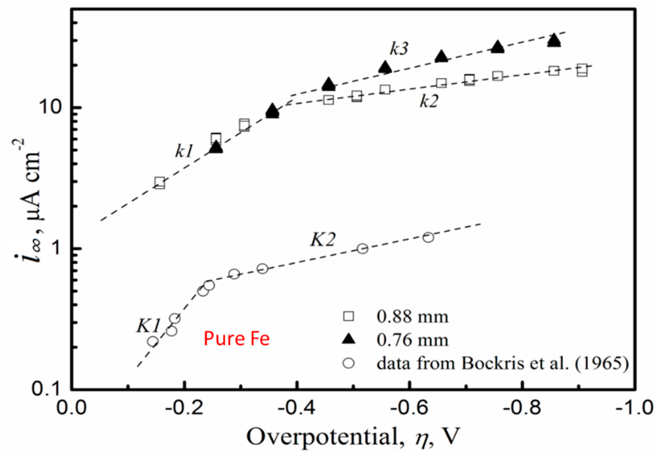
Figure 6.
Relation of hydrogen fugacity to charging over-potentials in 0.1 M NaOH solution and 0.1 M Na2SO4 pH 2 solution, compared with the prior data of Bockris et al. In this work, the pure Fe was annealed low interstitial steel and was pre-charged at −1.500 VAg/AgCl in 0.1 M NaOH solution for 48 h to achieve steady-state surface conditions on the input side [4].

Figure 7.
The thermal desorption spectroscopy (TDS-GU) apparatus [9].
Figure 7.
The thermal desorption spectroscopy (TDS-GU) apparatus [9].

Figure 8.
(a) TDS-GU spectra for 3.5NiCrMoV specimens electrochemically charged at different potentials in 0.1 M Na2SO4 solution at 25 °C for 24 h. (b) TDS-C spectra for 3.5NiCrMoV specimens electrochemically charged at different potentials in 0.1 M NaOH solution at 25 °C for 24 h [10].
Figure 8.
(a) TDS-GU spectra for 3.5NiCrMoV specimens electrochemically charged at different potentials in 0.1 M Na2SO4 solution at 25 °C for 24 h. (b) TDS-C spectra for 3.5NiCrMoV specimens electrochemically charged at different potentials in 0.1 M NaOH solution at 25 °C for 24 h [10].

Figure 9.
Deconvolution of composite peak below 250 °C of the TDS-GU spectra for 3.5NiCrMoV specimens electrochemically charged at different potentials in 0.1 M Na2SO4 solution at 25 °C for 24 h [10].
Figure 9.
Deconvolution of composite peak below 250 °C of the TDS-GU spectra for 3.5NiCrMoV specimens electrochemically charged at different potentials in 0.1 M Na2SO4 solution at 25 °C for 24 h [10].

Figure 10.
Deconvolution of composite peak below 250 °C of the TDS-GU spectra for 3.5NiCrMoV charged in gaseous hydrogen at the stated pressure for 24 h [10].
Figure 10.
Deconvolution of composite peak below 250 °C of the TDS-GU spectra for 3.5NiCrMoV charged in gaseous hydrogen at the stated pressure for 24 h [10].

Figure 11.
Hydrogen concentration for gaseous charged specimens established the trend line as a function of square root of charging pressure according to Sieverts’ Law. The hydrogen concentration of the cathodic charged specimens were plotted on this line to establish their equivalent hydrogen charging pressure. The intercept represents the amount of hydrogen in deep traps [10].

Figure 12.
Equivalent hydrogen fugacity for the 3.5NiCrMoV steel as a function of cathodic charging overpotential (full data points) compared with pure Fe (open symbols). In addition, given on the right hand axis is the corresponding hydrogen pressure [10].
Figure 12.
Equivalent hydrogen fugacity for the 3.5NiCrMoV steel as a function of cathodic charging overpotential (full data points) compared with pure Fe (open symbols). In addition, given on the right hand axis is the corresponding hydrogen pressure [10].


Figure 15.
Typical LIST potential drop data for 3.5NiCrMoV steel tested in air or for cathodic hydrogen charging at the stated potentials in 0.1 M Na2SO4 pH 2 [2].
Figure 15.
Typical LIST potential drop data for 3.5NiCrMoV steel tested in air or for cathodic hydrogen charging at the stated potentials in 0.1 M Na2SO4 pH 2 [2].

Figure 16.
The appearance of LIST specimens for 3.5NiCrMoV steel tested in air, or at the free corrosion potential, or for cathodic hydrogen charging at the stated potentials in 0.1 M Na2SO4 pH 2. Shown are over-views of the side of the specimen and magnified views of the specimen surface close to the final fracture [2].

Figure 17.
Typical appearance of 3.5NiCrMoV steel LIST specimen tested with cathodic hydrogen charging at −950 mVAg/AgCl in 0.1 M Na2SO4 pH 2. Shown are the over-view of the specimen fracture (upper central figure) and the indicated magnified fracture views of the regions (A–C) marked on the overview figure [2].

Figure 18.
S-N diagram for 3.5NiCrMoV, tested as a notched specimen, in air and with cathodic hydrogen charging at the stated potentials in 0.1 M Na2SO4 pH 2 [8].
Figure 18.
S-N diagram for 3.5NiCrMoV, tested as a notched specimen, in air and with cathodic hydrogen charging at the stated potentials in 0.1 M Na2SO4 pH 2 [8].


Table 1.
Chemical compositions of the steels (wt %) as determined by two independent measurements [2,3].
| Steel | Composition, wt % | |||||||||||
|---|---|---|---|---|---|---|---|---|---|---|---|---|
| C | Mn | Cr | Ni | Mo | V | Cu | Si | Al | S | P | Nb or Ti | |
| NiCrMo1 | 0.09 | 0.88 | 0.52 | 1.04 | 0.60 | 0.01 | 0.06 | 0.31 | 0.017 | 0.01 | 0.01 | <0.01 |
| 0.08 | 0.91 | 0.48 | 0.98 | 0.60 | 0.01 | 0.06 | 0.31 | 0.018 | 0.01 | 0.01 | <0.01 | |
| 3.5NiCrMoV | 0.22 | 0.23 | 1.67 | 2.77 | 0.43 | 0.09 | 0.09 | 0.08 | <0.005 | 0.01 | 0.01 | <0.01 |
| 0.21 | 0.22 | 1.65 | 2.75 | 0.41 | 0.09 | 0.09 | 0.07 | <0.005 | 0.01 | 0.01 | <0.01 | |
| 27NiCrMoV15-6 | 0.25 | 0.24 | 1.52 | 3.50 | 0.40 | 0.11 | 0.08 | 0.08 | <0.005 | 0.01 | 0.01 | <0.01 |
| 0.27 | 0.24 | 1.55 | 3.50 | 0.41 | 0.12 | 0.08 | 0.08 | <0.005 | 0.01 | 0.01 | <0.01 | |
| 34CrNiMo6 | 0.38 | 0.59 | 1.61 | 1.5 | 0.18 | 0.01 | 0.18 | 0.23 | 0.025 | 0.01 | 0.01 | <0.01 |
| 0.38 | 0.60 | 1.63 | 1.49 | 0.18 | 0.01 | 0.18 | 0.24 | 0.026 | 0.01 | 0.01 | <0.01 | |
Table 2.
Yield stress in air and in the solution, as an engineering stress, σY, the fracture stress, as an engineering stress, σF, and the reduction in area, RA, for 3.5NiCrMoV subject to LIST at the stated applied stress rate. Testing in the 0.1 M Na2SO4 pH2.0 solution was at the corrosion potential, Ecorr, or at the stated potential [2].
| Air or Applied Potential, mVAg/AgCl | Applied Stress Rate MPa/s | σY, MPa | σF, MPa | RA, % |
|---|---|---|---|---|
| Air | 0.2 | 650 | 770 | 79 |
| Air | 0.2 | 681 | 796 | 79 |
| Air | 0.02 | 671 | 793 | 78 |
| Air | 0.002 | 656 | 772 | 79 |
| Ecorr | 0.2 | 719 | 841 | 81 |
| Ecorr | 0.2 | 719 | 850 | 80 |
| Ecorr | 0.02 | 710 | 818 | 80 |
| Ecorr | 0.002 | 695 | 807 | 82 |
| −950 | 0.02 | 737 | 840 | 36 |
| −950 | 0.02 | 685 | 788 | 78 |
| −950 | 0.002 | 693 | 802 | 73 |
| −1200 | 0.02 | 702 | 816 | 64 |
| −1200 | 0.02 | 678 | 784 | 75 |
| −1200 | 0.002 | 687 | 798 | 72 |
| −1400 | 0.02 | 685 | 792 | 64 |
| −1700 | 0.02 | 680 | 774 | 50 |
| −1700 | 0.2 | 688 | 811 | 72 |
© 2018 by the authors. Licensee MDPI, Basel, Switzerland. This article is an open access article distributed under the terms and conditions of the Creative Commons Attribution (CC BY) license (http://creativecommons.org/licenses/by/4.0/).
Share and Cite
MDPI and ACS Style
Atrens, A.; Liu, Q.; Tapia-Bastidas, C.; Gray, E.; Irwanto, B.; Venezuela, J.; Liu, Q. Influence of Hydrogen on Steel Components for Clean Energy. Corros. Mater. Degrad. 2020, 1, 3-26. https://doi.org/10.3390/cmd1010002
AMA Style
Atrens A, Liu Q, Tapia-Bastidas C, Gray E, Irwanto B, Venezuela J, Liu Q. Influence of Hydrogen on Steel Components for Clean Energy. Corrosion and Materials Degradation. 2020; 1(1):3-26. https://doi.org/10.3390/cmd1010002
Chicago/Turabian StyleAtrens, Andrej, Qian Liu, Clotario Tapia-Bastidas, Evan Gray, Bartolomeus Irwanto, Jeff Venezuela, and Qinglong Liu. 2020. "Influence of Hydrogen on Steel Components for Clean Energy" Corrosion and Materials Degradation 1, no. 1: 3-26. https://doi.org/10.3390/cmd1010002