Modeling and Simulation of a Novel Combined Solar Photovoltaic-Thermal Panel and Heat Pump Hybrid System

1
Research Center for renewable Energy, Catholic University of Cuenca, Cuenca 010150, Ecuador
2
TransPacific Energy, Inc., Henderson, NV 89183, USA
Clean Technol. 2019, 1(1), 89-113; https://doi.org/10.3390/cleantechnol1010007
Submission received: 13 July 2018
/
Revised: 3 August 2018
/
Accepted: 7 August 2018
/
Published: 13 August 2018
Abstract
:A numerical simulation model for a novel concept of a hybrid composed of photovoltaic-thermal solar panels and a heat pump is presented. This concept was developed to assess the performance and energy conversion efficiency of the hybrid system used to produce domestic hot water and electricity. A two-dimensional heat transfer and fluid flow dynamic model was developed to describe the behavior of the hybrid system under different solar irradiance, heat pump boundary conditions and different refrigerants. The model is based on dynamic mass and energy equations coupled with the heat transfer coefficients, and the thermodynamic properties of refrigerants as well as material properties. The model compared fairly to experimental data.
1. Introduction
Currently, the efficiency of commercial solar photovoltaic (PV) systems is up to 15% while more than 85% of incoming solar radiation energy is either absorbed or reflected; therefore, significant excess heat is dissipated and wasted. New PV technologies reported in the literature [1,2,3,4,5,6,7,8,9,10,11,12,13,14,15,16,17,18,19,20,21,22,23,24,25,26,27,28,29] have been shown to improve the energy utilization efficiency of solar PV, such as multi-junction cells, optical frequency shifting, and concentrated photovoltaic (CPV) systems, among others; however, these are expensive. In order to improve the efficiency of solar PVs a novel concept of a combined photovoltaic-thermal solar panel hybrid system has been developed and implemented [3,4,5,6,7,8,9], where the PV cells of the solar PV panels are cooled by water flow. Excess thermal energy is generated and dissipated due to intrinsic limitations of the cell, that is, the excess thermal energy increases the cell temperature, which reduces the conversion efficiency of the cell. The excess thermal energy absorbed by the cold water flowing though the heat exchanger thermal panel underneath the PV cell can be used for various domestic or industrial applications. Therefore, the net result is an enhancement in the combined photovoltaic-thermal efficiency of the hybrid system.
A lower-grade heat pump can extract energy from a photovoltaic/thermal (PV/T) system that can be upgraded to higher temperatures for heating purposes in either domestic or industrial applications. Recent developments have been reported by [4,13,15] on the integration of heat pumps and photovoltaic technology including the use of photovoltaic solar assisted heat pump systems. A system using a solar-assisted heat pump and a PV/T collector as its evaporator was also reported by Ito et al. [17]. They indicated that the heat pump’s coefficient of performance (COP) was 6 at a water temperature of 40 °C at the inlet of the evaporator.
More recently, the performance of independent heat pump modes and hybrid loop heat pipe/heat pump modes were simulated and compared by Dai et al. [4]. Their findings showed that on typical sunny days, the hybrid loop heat pipe/heat pump mode saved 40.6% more power consumption than the heat pump mode. Furthermore, Sami and Tulej [23] presented a new concept in air-source heat pumps using a ternary refrigerant mixture specially designed for cold climates where other heat pumps failed due to the lower sink temperature. Their experimental and numerical results showed a significant enhancement in the COP over other standard air-source heat pumps.
There are a number of publications that have been reported on the installation of PV/T systems in buildings [20]. These publications present and discuss the different strategies for the use of PV/T in buildings and in various building projects. Since buildings demand electricity as well as heating and cooling, PV/T systems are an attractive solution because of their thermal efficiency and also less space is required for installation.
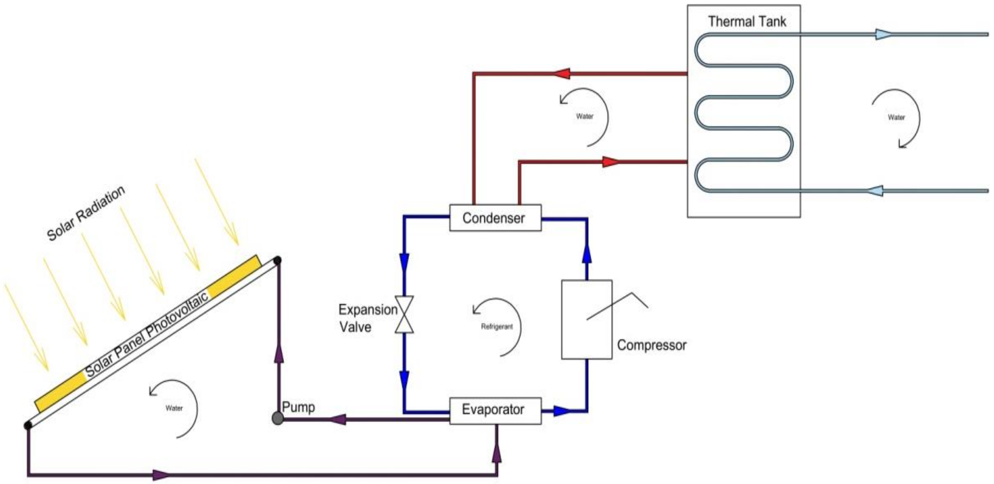
The modeling and simulation of a novel solar photovoltaic-thermal panel and heat pump hybrid system is presented in this paper. A schematic of the thermal solar hybrid system under study is depicted in Figure 1. This novel concept is intended to enhance the energy conversion efficiency of the PV-Thermal solar hybrid system through utilizing the excess thermal energy dissipated by the conversion process and water source heat pump to produce domestic hot water and enhance the energy conversion efficiency of the solar photovoltaic. The conceptual photovoltaic-thermal panel integrated heat pump design was modeled and analyzed using a two-dimensional dynamic model based upon the heat transfer and fluid flow conversion equations. The model was developed to describe the steady state and dynamic behavior of a combined photovoltaic cell-thermal panel, the water source heat pump hybrid system under different conditions of solar irradiance, material properties, ambient and fluid flow conditions, different refrigerants and excess thermal energy recovered by the panel, as well as boundary conditions. The predicted results presented herein include the efficiency of the energy conversion of the hybrid system, PV cell characteristics and heat pump behavior with different refrigerants, and finally, thermal energy recovered by the hybrid system panel and delivered for domestic and/or industrial use under different conditions. Comparative financial analysis of the novel solar photovoltaic-thermal and heat pump hybrid system is not presented in this paper.
2. Mathematical Model
The study presented herein is based on the work previously reported by Yang et al. [1], and references [2,3,4,5,6,7,8,9,10,11,12,13,14] where a flat plate solar collector is attached to a PV panel. The hybrid system in question is composed of the PV solar panel and thermal solar tube collector as well as a heat pump as shown in Figure 1. The PV solar panel and tube, water cooled PVT and the heat pump hybrid system was analyzed in this paper. This hybrid system consists of a photovoltaic panel welded on the backside and thin parallel tubes for the circulation of the cooling fluid. The various flow tubes in contact with the PV solar panel are connected to the evaporator of the heat pump, from which the water flows through the thermal solar collector copper pipes and carries the excess heat away from the solar PV panel and thermal panel as shown in Figure 1. The water-cooling loop of the heat pump condenser is connected to a thermal tank where it supplies the demand for hot water.
A typical PV panel’s output is in DC current and connected to a load controller and batteries as well as the inverter for converting the DC current output into AC current for potential use in applications where AC is required. In the following sections, the enhancement of the efficiency of the hybrid system and the characteristics of the solar PV/Thermal panel as well as the heat pump at various operating temperatures and different solar radiations will be presented.
3. Solar PV Model
The solar photovoltaic panel is constructed of various modules and each module is consisted of arrays and cells. The dynamic current output can be obtained as follows [18,19,20,21,22], and [30,31]:
- Ip: Output current of the PV module
- IL: Light generated current per module
- Io: Reverse saturation current per module
- V: Terminal voltage per module
- Rs: Diode series resistance per module
- Rsh: Diode shunt resistance per module
- q: Electric charge
- k: The Boltzman constant
- A: Diode ideality factor for the module
Here,
and
The PV cell temperature, Tc, is influenced by various factors such as solar radiation, ambient conditions, and wind speed. It is well known that the cell temperature impacts the PV output current, performance and its time-variation can be determined from [18,19,20,21,22]. The AC power of the inverter output P(t) is calculated using the inverter efficiency , output voltage between phases, neutral , and for single-phase current and as follows:
4. PV Thermal Model
The following thermal analysis is performed for a single PV cell, however, it is assumed that all PV cells behave the same, therefore, it can be applied to the whole PV solar panel.
- αabs: Overall absorption coefficient
- G: Total solar radiation incident on the PV module
- Sp: Total area of the PV module
- TC: PV cell temperature
- mCp_module: Thermal capacity of the PV module
- t: time
- Qin: Energy received due to solar irradiation, Equation (4)
- Qconv: Energy loss due to convection
- Qelect: Electrical power generated
5. Thermal Energy Incident in a PV Cell
The thermal energy transferred from the PV cell to the heat transfer fluid (HTF) is determined from the heat balance across the PV cell and HTF in terms of the heat transfer mechanisms; conduction, convection and radiation as follows [30,31].
The heat transfer by conduction is:
- Tm: Module back-surface temperature
- KPv: Thermal conductivity of PV cell
- Lcell: Length of a PV cell
- ∆T: the temperature difference Tc − Tm
The heat transfer by convection is determined from
- Qconvection: Energy due to convection
- hwater: Heat transfer coefficient
- Tf: Fluid temperature
- ∆T: the temperature difference Tm − Tf
The heat transfer by radiation is:
- : Emissivity PV cell
- : Stefan-Boltzmann constant
On the other hand, Equation (8) can be rewritten as follows:
- ṁw: Water mass flow (HTF)
- Cp-water: Specific heat of water
- TfHx: Maximum temperature difference at the Heat Exchanger heat tubes
The finite difference formulation is used to determine the heat transfer fluid temperatures at each element where the heat transfer fluid tube is divided into a number of thermal elements:
- t: time
- δQ: the heat transfer per element
- Tf_in: Fluid temperature at inlet
- Cp: is the water specific heat
The thermal energy transferred from the PV cell to the heat transfer fluid (HTF) is obtained by:
- QThermal: Energy from thermal process
- TfHx+1: Fluid temperature at thermal element 1
- ∆T: Temperature difference TfH+1 − Tf in
The energy transferred to the heat transfer fluid is calculated from the integration of Equations (6)–(12) written for each element, dx, along the length of each tube.
It is worthwhile mentioning that the PV cell and panel temperature is influenced by different factors and in particular, the ambient conditions such as the temperature, humidity and wind speed among other parameters.
The back temperature Tm of the PV cell and PV panel can be calculated from the heat balance across the PV cell as follows [30]:
where Tm is the module back-surface temperature and Tc is the PV cell temperature.
It is assumed that Tm is equal to the surface temperature of the heat exchanger tubes welded to the solar PV cell/panel in close contact to the back surface of each of the PV cells. The heat transferred from the back of the PV cell to the heat transfer fluid flowing in the heat exchanger tubes as shown in Figure 1 is computed by the following forced heat transfer convection relationship [16,19]:
- D: Pipe diameter
- L: Pipe length
- hwater: Forced convection heat transfer coefficient
- Tf: Fluid temperature
The heat transfer coefficient, hwater, is approximated as in [30]:
and
where Re is the Reynolds Number and Kw represents the thermal conductivity of water, b2, n are numerical constants, and mw is the water HTF mass flow rate.
Finally, to calculate the heat transfer fluid flow rate, the following equation is used,
- ṁw: Water flow
- Tf+1: Water temperature at the next element
- Cp-water: Specific heat of HTF
6. Heat Pump Model
In the following the steady state energy balance equations of the water source heat pump are presented as in [23], and [15,16,17,18,19,20,21,22].
The refrigerant mass flow rate circulating in the heat pump in question can be calculated as follows:
where T9 and T10 are the inlet and outlet temperatures of the HTF to the evaporator, respectively.
The heat compressor power required to drive the heat pump is:
where is the compressor efficiency.
The condenser heat capacity can be calculated as follows:
and,
where the h1, h2, h3 and h4 are the enthalpies of the refrigerant at the inlet and outlet of the compressor, and the inlet and outlet to the expansion valve, respectively. The enthalpies of the refrigerants were determined using pressure and temperature [32].
Finally, the coefficient of performance COP which describes the heat pump efficiency is:
Qcond and Qcomp are the thermal energy at the condenser and compressor, respectively.
On the other hand, the thermal energy drawn from the thermal tank and delivered for domestic or industrial use is:
where the mwQtt represents the water mass flow rate circulating between the thermal tank and the user application in question. T7 and T8 are the supply and return temperature from the user application, respectively.
Furthermore, the evaporator heat capacity is:
The water mass flow rate in the condenser-thermal tank loop can be calculated by the following equation:
The water mass flow rate for supplying hot water to the use application is:
Finally, the hybrid system energy conversion efficiency for harnessing energy from solar PV and solar thermal and solar PV and heat pump but not supplying the compressor power is:
while the hybrid system efficiency with the solar PV panels supply the compressor power is:
and the solar PV panel’s efficiency is:
and the PV thermal solar efficiency is:
where Qth and Qin are the solar thermal heat transferred to the HTF and solar irradiance, respectively. PV represents the power supplied by the PV solar panels.
The respective values are given by Equations (1) and (29), respectively. In addition, is the PV solar electrical output and defined by Equation (4).
7. Numerical Procedure
The energy conversion and heat transfer mechanisms taking place during various processes for the solar PV-Thermal and heat pump, as shown in Figure 1, are described in Equations (1)–(29). The model presented here is based on mass and energy balances of the individual components of the PV/T hybrid system; PV cell and the heat transfer fluid flowing in thermal tubes welded in the back of the PV panel and driving the heat pump. This enables the calculation of the electrical power output of the solar PV panel, thermal energy recovered from the solar PV panel and supplied to the heat pump, and thermal characteristics of the water flow driving the heat pump, the hybrid system total and individual efficiencies in terms of solar radiation and other geometrical parameters.
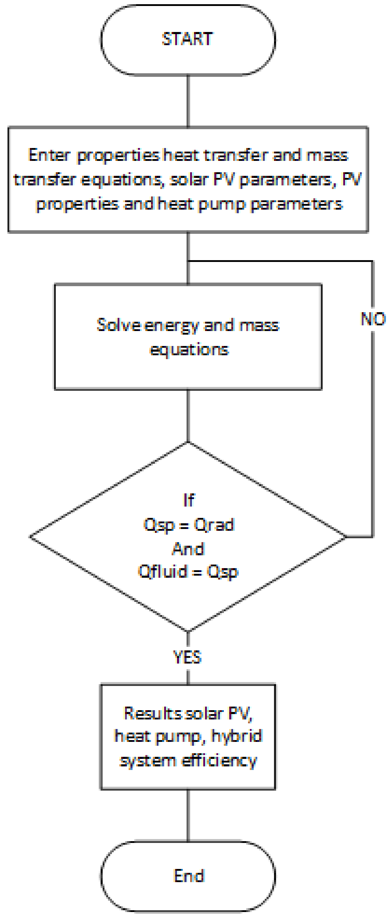
These equations have been solved as per the logical flow diagram presented in Figure 2, where, the input parameters of the solar PV conditions such as solar radiation, ambient temperature and humidity as well as other independent parameters for the solar thermal tubes and heat pump are defined. Dependent parameters were calculated and integrated in the finite-difference formulations. Iterations were performed until a converged solution was reached with acceptable iteration error.
The numerical procedure starts with the solar radiation, ambient conditions to calculate the solar PV cell temperature, and PV cell back temperature as well as heat transfer fluid mass flow characteristics circulating in the thermal closed loop at specified conditions. The thermodynamic and thermophysical properties of the heat transfer fluid were employed to calculate the water flow rate. This was followed by the finite-difference formulations to predict the time variation of the PV cell temperature, the PV back temperature, and thermal heat transferred to the heat transfer fluid, and the heat transfer fluid outlet temperature at the heat exchanger. The heat transfer fluid drives the evaporator of the heat pump. This step was followed by the selection of the heat pump refrigerant and refrigerant mixture, operating conditions, and the thermodynamic and thermophysical properties of the refrigerant circulating in the heat pump loop. Finally, other hybrid system thermal and power outputs and individual efficiencies were calculated as well as the hybrid system efficiency at each input condition.
8. Results and Discussion
In order to solve the aforementioned Equations (1)–(29) and taking into account the heat and mass transfer during the solar PV thermal and heat pump conversion processes, the above-mentioned equations were coded, integrated using the finite-difference formulations, and solved as per the logical flow chart depicted in Figure 2. In addition, for the purpose of validation, the predicted simulated results for PV solar panel under various conditions were compared to the data published in the literature.
In the following sections, we present analysis and discussions of the numerical results predicted as well as validation of the proposed simulation model. The simulations were performed at different temperatures across the heat exchanger flow pipes bonded to the back of the solar PV panel. However, only the results for the temperature difference of 15 °C across the thermal tube will be presented. It is worthwhile noting that the numerical simulation presented hereby was conducted under different conditions including: PV cell temperatures from 10 °C through to 75 °C, ambient temperatures from 10 °C through to 38 °C, solar radiation of 550, 750, 1000 and 1200 W/m2,different refrigerants such as R-134a (HFC 134a), R-410A (HFC 32, HFC 125), R-407C (HFC32, HFC125, HFC134a), R-507 (HFC 125, HFC 143a), and mixtures of the aforementioned refrigerants components [32].
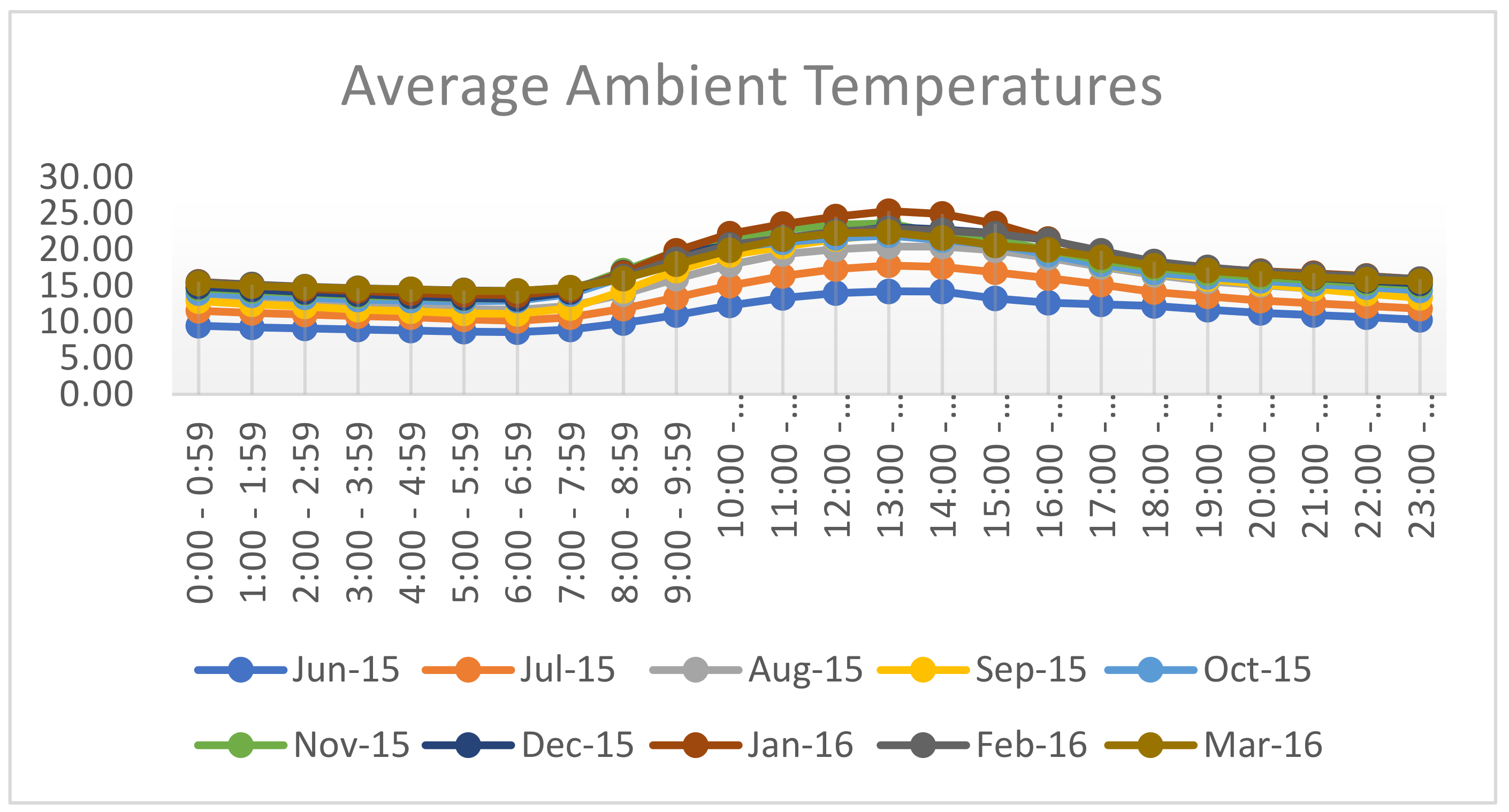
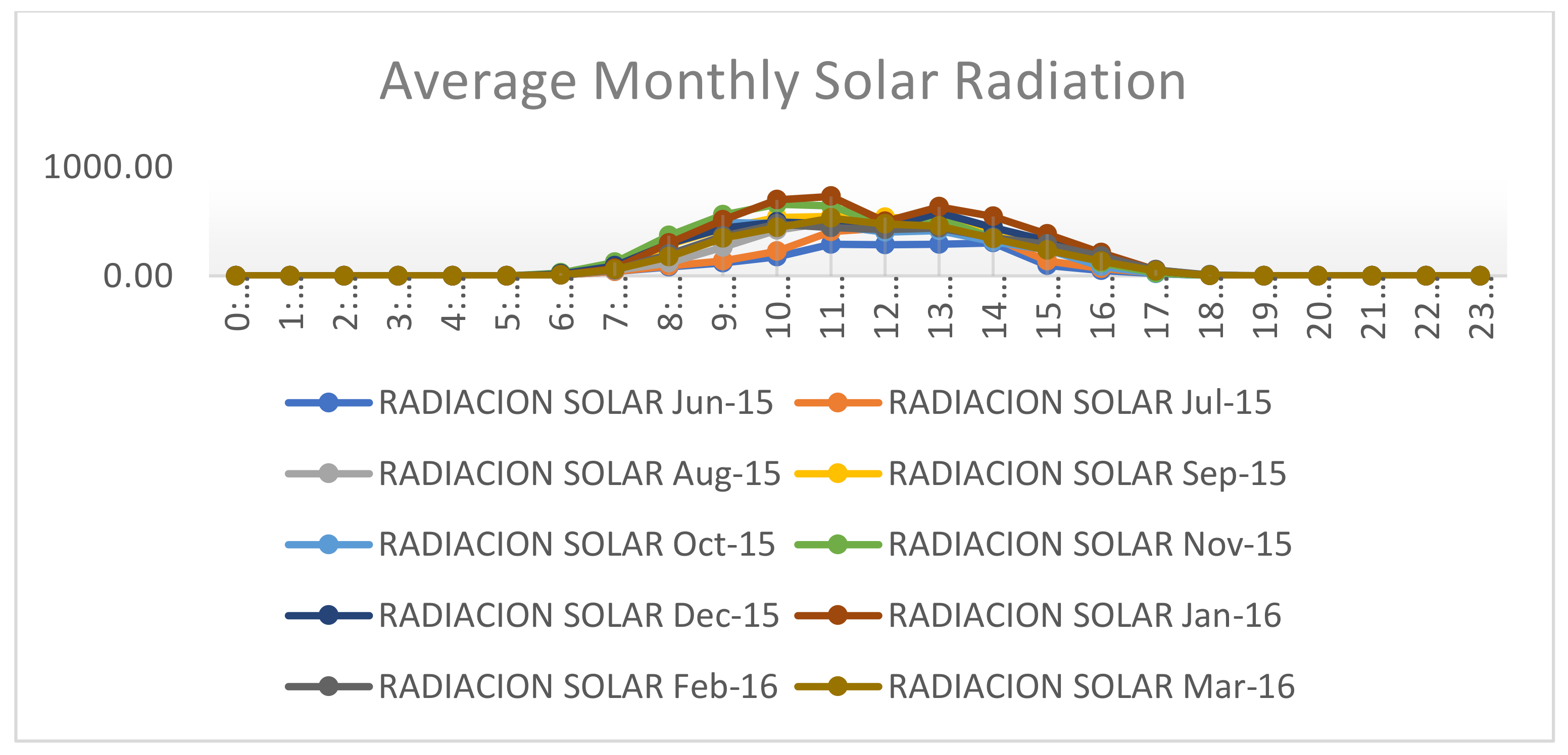
Figure 3 and Figure 4 present a typical ambient temperature and solar isolation profile at a site located in Ecuador for various months during 2015 and 2016, at different hours of the day. It is quite apparent that the peak solar irradiation and maximum temperatures occur at midday. However, average solar irradiation and ambient temperatures were used in the modeling and simulation of the photovoltaic panels. The recording of the ambient conditions during this period showed that the relative humidity is stable during most hours of the day. Therefore, in the simulation of the PV thermal solar panel relative humilities were assumed to be constant.
The PV characteristic curves are given in the manufacturer’s specification sheet. The PV panel characteristic curves under consideration in this study were obtained from Fahmy et al. [22]. The parameters used in this study are: the total surface area of the PV module (SP) is 0.617 m2, the total surface area of cells in module (Sc) is 0.5625 m2, module efficiency is 12% at reference temperature (298 K), overall absorption coefficient is 0.73, and temperature coefficient is 0.0045 K−1. Readers interested in the full range of values of the other parameters are advised to consult Fahmy et al. [22].
It was also assumed in this simulation that the whole panel is covered in PV cells, with no packing material (material used to fill in gaps between the cells on a panel). The PV cells are commercial grade monocrystalline silicon cells with electrical efficiency of 12%, and have a thermal coefficient, of 0.54% [1/K], however, it is dependent upon the rated solar radiation [22]. The thermal coefficient represents the degradation of PV cell output per degree of temperature increase. The heat exchanger pipes are bonded to the back of the PV solar model without any air gap to ensure complete heat transfer by conduction, convection and radiation to the fluid flowing in the thermal pipes. The exiting temperatures of the heat transfer fluid vary between 25 °C and 50 °C. This heat transfer fluid drives the evaporator of the heat pump and the thermal heat absorbed from the heat transfer fluid evaporates the refrigerant in the evaporator of the heat pump. The vapor refrigerant is then compressed by the compressor to higher temperatures and pressures and dissipates its condensation heat to the water cooling the condenser. The refrigerant is then throttled by an expansion device to the evaporator. The heat of condensation of the refrigerant is released to water in the thermal tank.
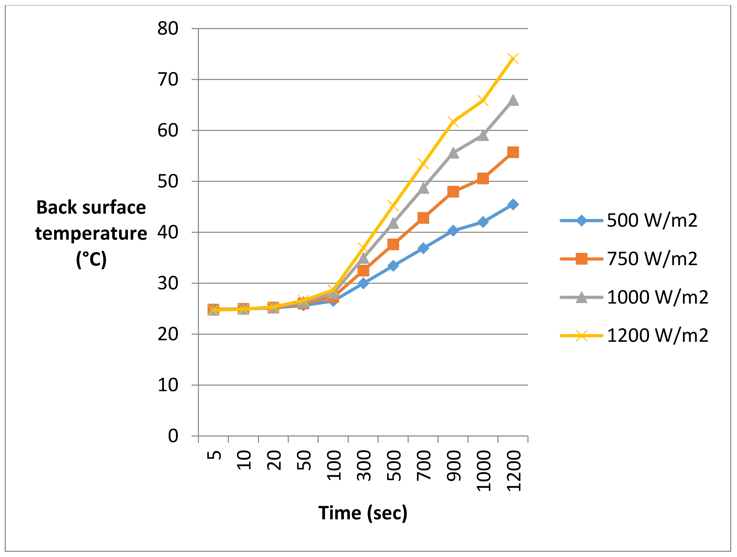
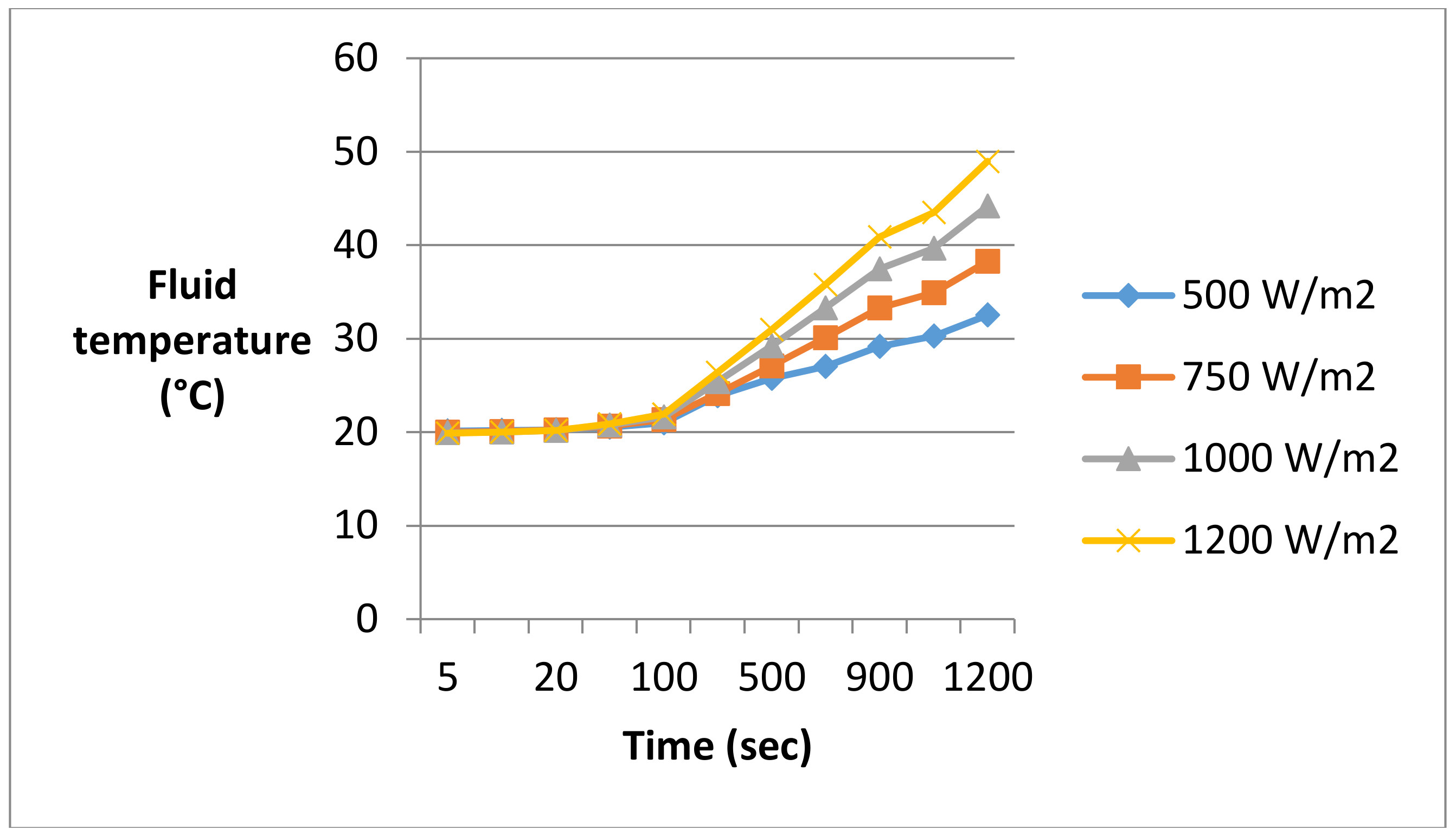
As per Equations (6)–(22), an increase in the PV cell temperature will result in an increase in the back cell temperature and consequently the fluid temperature due to the heat transfer by from solar energy by conduction and convection as well as radiation, respectively. Consequently, this increases the thermal heat driving the evaporator of the heat pump and increases the thermal energy transferred to the thermal tank. Furthermore, Figure 5, Figure 6, Figure 7 and Figure 8 demonstrate that the higher the cell temperature the higher the back cell and fluid temperatures as well as the thermal energy delivered to the evaporator. It is evident from the results presented in these figures that the cell temperature increases with the increase in solar radiation. This can be interpreted as per Equations (1) and (2), where the higher the solar radiation, the higher the energy absorbed by the PV cell, and consequently, the higher the temperature of the cell until it reaches the design temperature.
The effects of the PV panel operating temperature on the output efficiency have been well documented in the literature [21,22], where increasing the temperature of the PV cell decreases the amount of power available. In order to evaluate the efficiency of a PV system, the temporal temperature variations are often regarded as instantaneous in steady state models. However, it is important to note that the changes in the PV cell temperature caused by solar radiation have a dynamic nature, as demonstrated in Figure 5. The PV panel heats up and cools down gradually in a dynamic response depending upon the changes in solar radiation and consequently changes the power output from the PV panel.
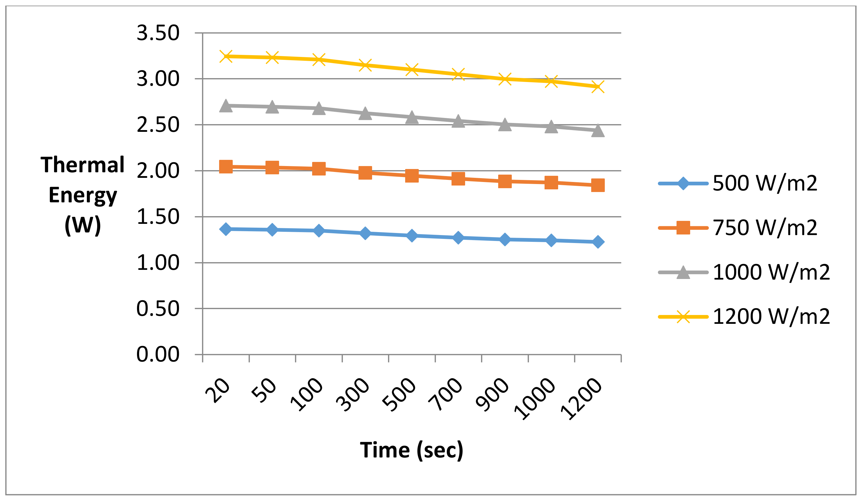
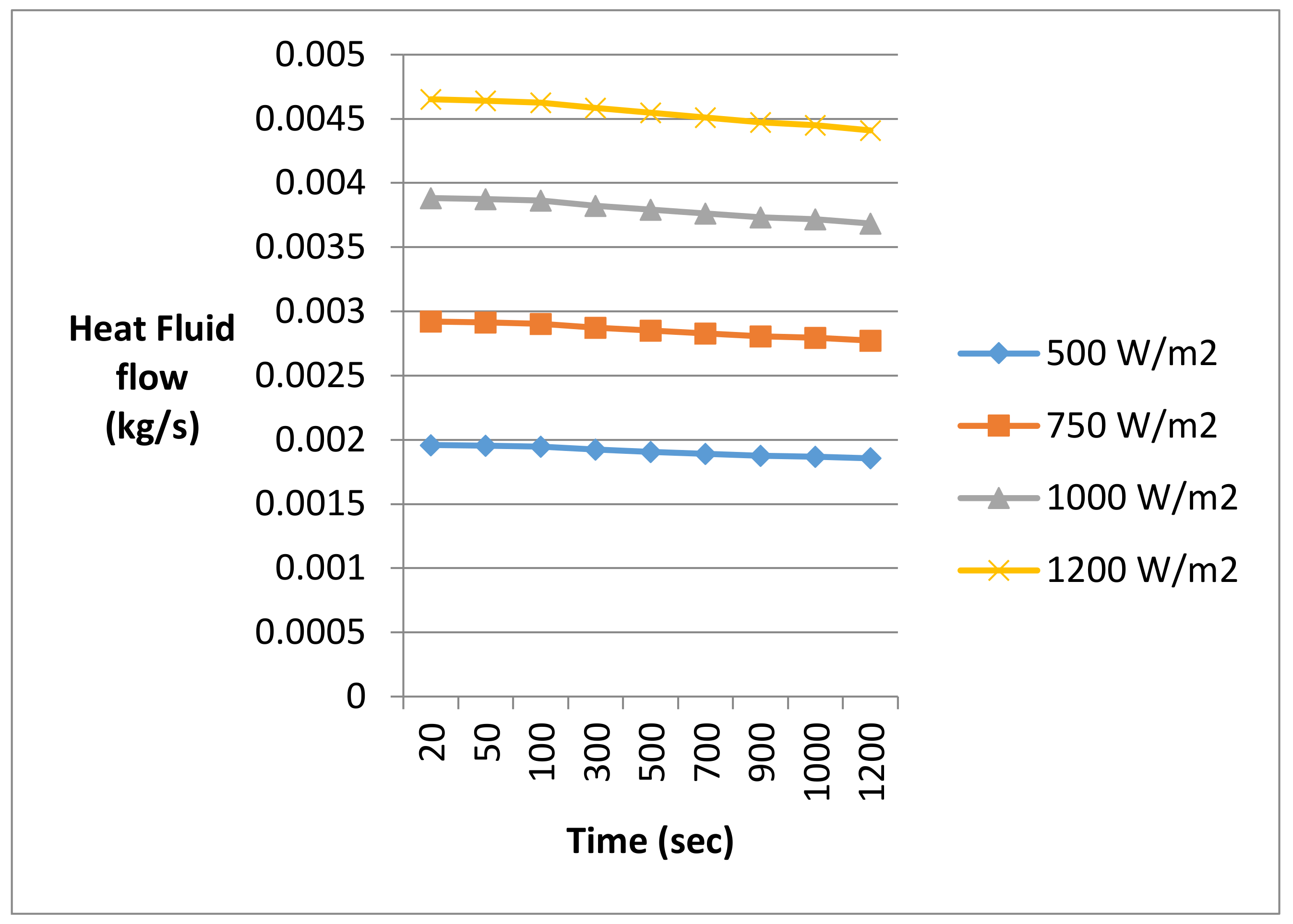
The dynamic behavior of the thermal energy absorbed by the fluid flow flowing beneath the PV solar cell is determined by Equations (11) and (16) and plotted in Figure 8 under different solar radiation. The results presented in this figure show that the higher the solar radiation, the higher the thermal energy absorbed. The figure also shows that once the cell temperature stabilizes the thermal energy absorbed reaches a steady state level. On the other hand, the results also indicated that the systems stabilized after 1200 s and the desired water flow outlet was reached after this time elapsed, as shown in Figure 9. As expected the heat transfer fluid mass flow rate increased at higher solar radiation and also stabilized at 1200 s. This is due to the fact that the higher solar radiation results in higher thermal energy being transferred to the fluid flow at constant temperature difference across the fluid flow thermal pipe, and consequently, this increases the fluid flow mass flow rate. Furthermore, the results presented in this figure also suggest that the fluid flow mass flow rate is quasi-constant during the thermal conversion process.
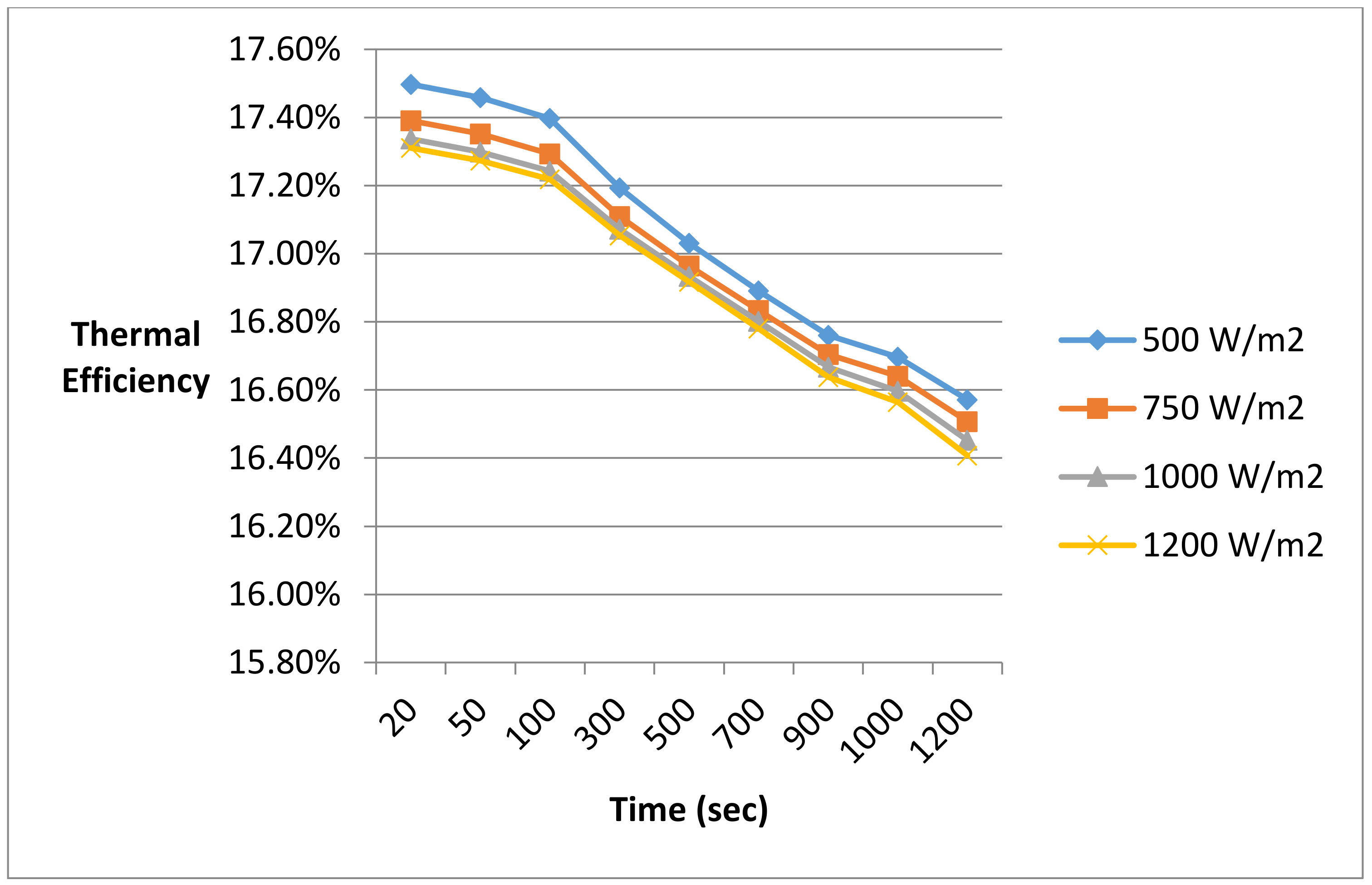
The efficiency of the convective thermal energy transferred to the fluid flow flowing beneath the PV cell is depicted in Figure 10, where the energy conversion efficiency is plotted at different solar radiation at different time steps. The thermal efficiency is defined as the heat transferred divided by the solar radiation absorbed by the PV panel. It is evident from the results presented in this figure, that the higher the solar radiation, the higher the thermal conversion efficiency. On the other hand, the figure also shows that for longer time spans, the thermal energy conversion efficiency diminishes.
The series of numerical calculations using Equation (28) concluded that the solar PV efficiency for one solar PV panel at different solar radiation and refrigerant R-134a is 22.38% based on the geometrical configuration of the solar PV panel reported in reference [22].
Furthermore, as shown in Figure 1, this novel concept is intended to enhance the energy conversion efficiency of the PV-Thermal solar hybrid system through utilizing the excess thermal energy dissipated by the conversion process to drive the water-source heat pump to produce domestic hot water (DHW), and enhance the energy conversion efficiency of the solar photovoltaic. As PV solar panel efficiency calculations showed, the higher the solar radiation, the higher the solar PV current, which consequently increases the solar PV power output, however, the PV solar panel efficiency remained constant at 22.38% and is independent of the type of refrigerant used in the heat pump system.
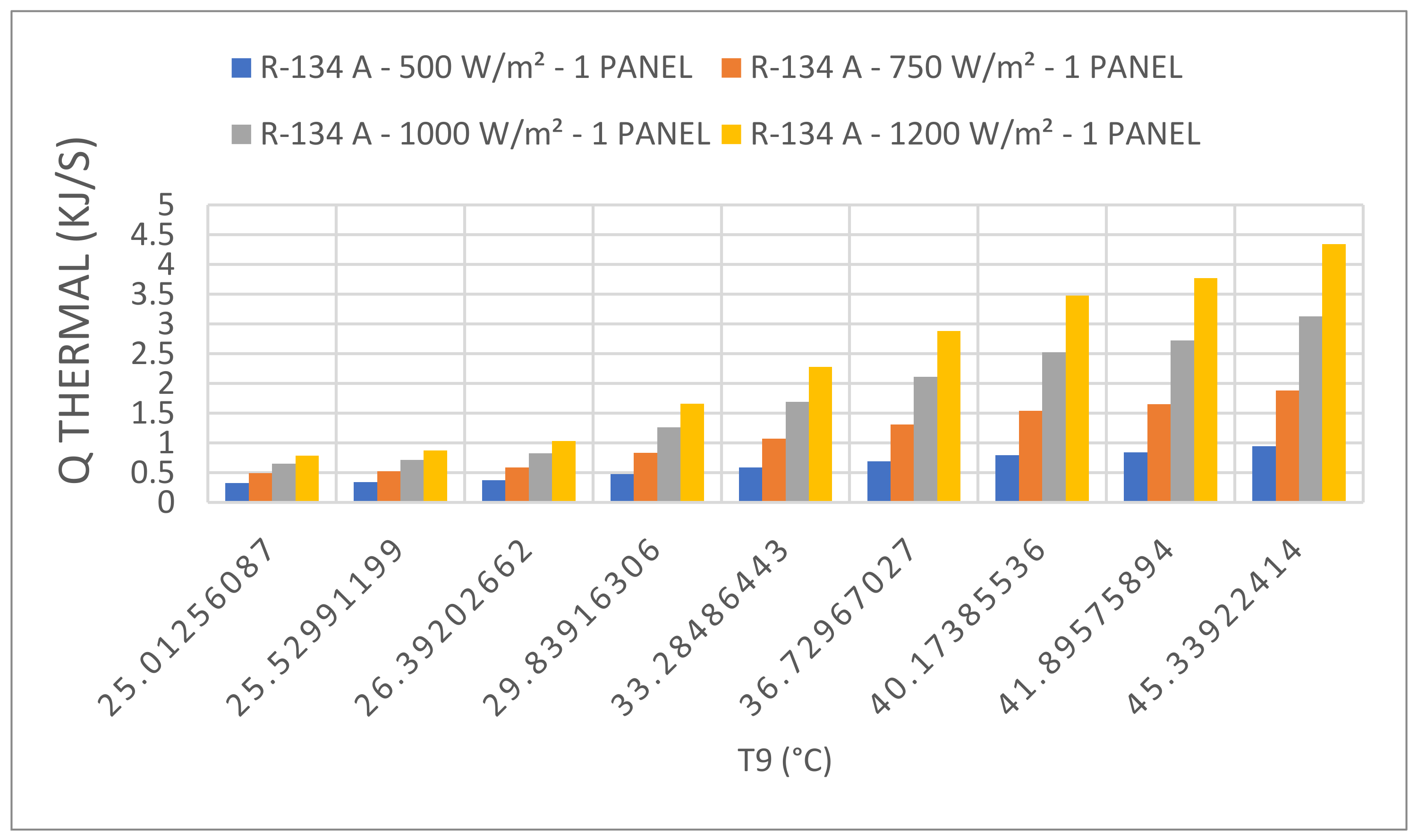
The thermal heat transferred to the heat pump evaporator as well as the entering temperature to the heat pump evaporator were plotted and are presented in Figure 11 at different solar radiation with the heat pump using refrigerant R-134a. This was necessary to examine the impact of the solar radiation on the heat pump performance. It is clear from the results presented in this figure that the higher the solar radiations, the higher the evaporator entering temperatures, and the higher the thermal heat transferred to the heat pump evaporator. The thermal heat absorbed by the evaporator evaporates the refrigerant circulating in the heat pump, which is compressed by the compressor to higher temperature and pressure and thermal energy at the condenser side. Similar behavior was observed for the other refrigerants used in the heat pump under investigation. Comparison between the heats released with different refrigerants is discussed elsewhere in the paper.
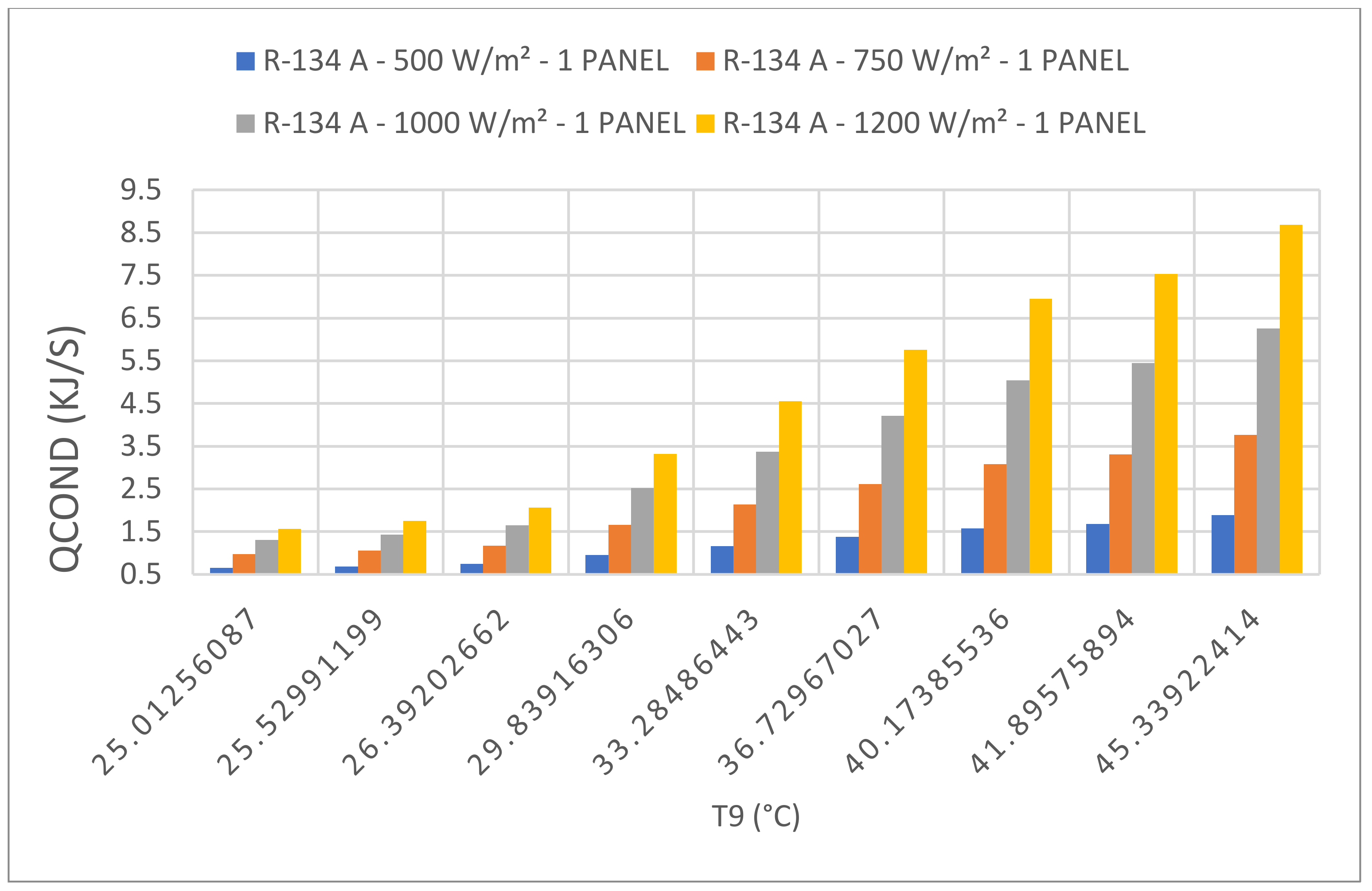
The heat transfer fluid temperatures entering the heat pump evaporator and the condenser heat released to the condenser cooling fluid were plotted and are presented in Figure 12 at different solar radiation and a heat exchanger temperature difference of 15 °C with refrigerant R-134a. Examining the results presented in this figure clearly indicates that the higher the solar radiations, the higher the evaporator entering temperature, and the higher the heat released from the heat pump condenser. The thermal heat released delivers higher thermal energy to the thermal tank through the cooling water flow of the condenser, which in turn heats up the water in the thermal tank. Consequently, the data shows that the higher solar radiation, the higher the water temperature in the thermal tank which is supplied for domestic or industrial demand. Similar behavior has been observed for the other refrigerants used in the heat pump under investigation. Comparison between the heats released for different refrigerants is discussed elsewhere in the paper.
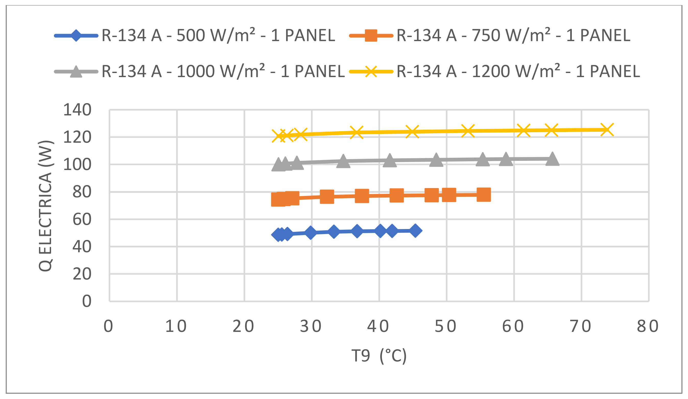
The impact of the different temperatures entering the heat pump evaporator on the electric power generated by one cell of the solar PV panel was plotted and presented in Figure 13 at different solar radiation and a heat exchanger temperature difference of 15 °C, as well as for using refrigerant R134a in the heat pump cycle. It is quite clear that the higher the solar radiation, the higher the amount of electric power produced by the solar PV panel.
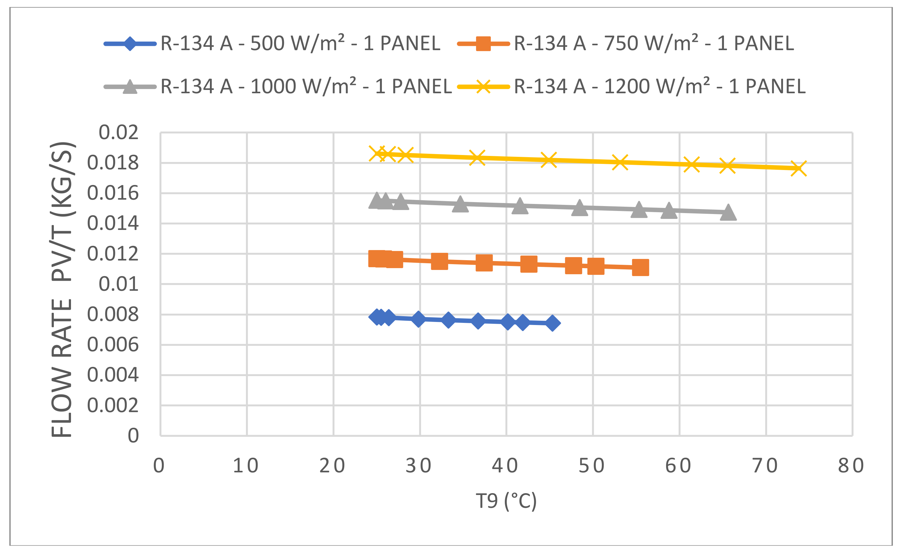
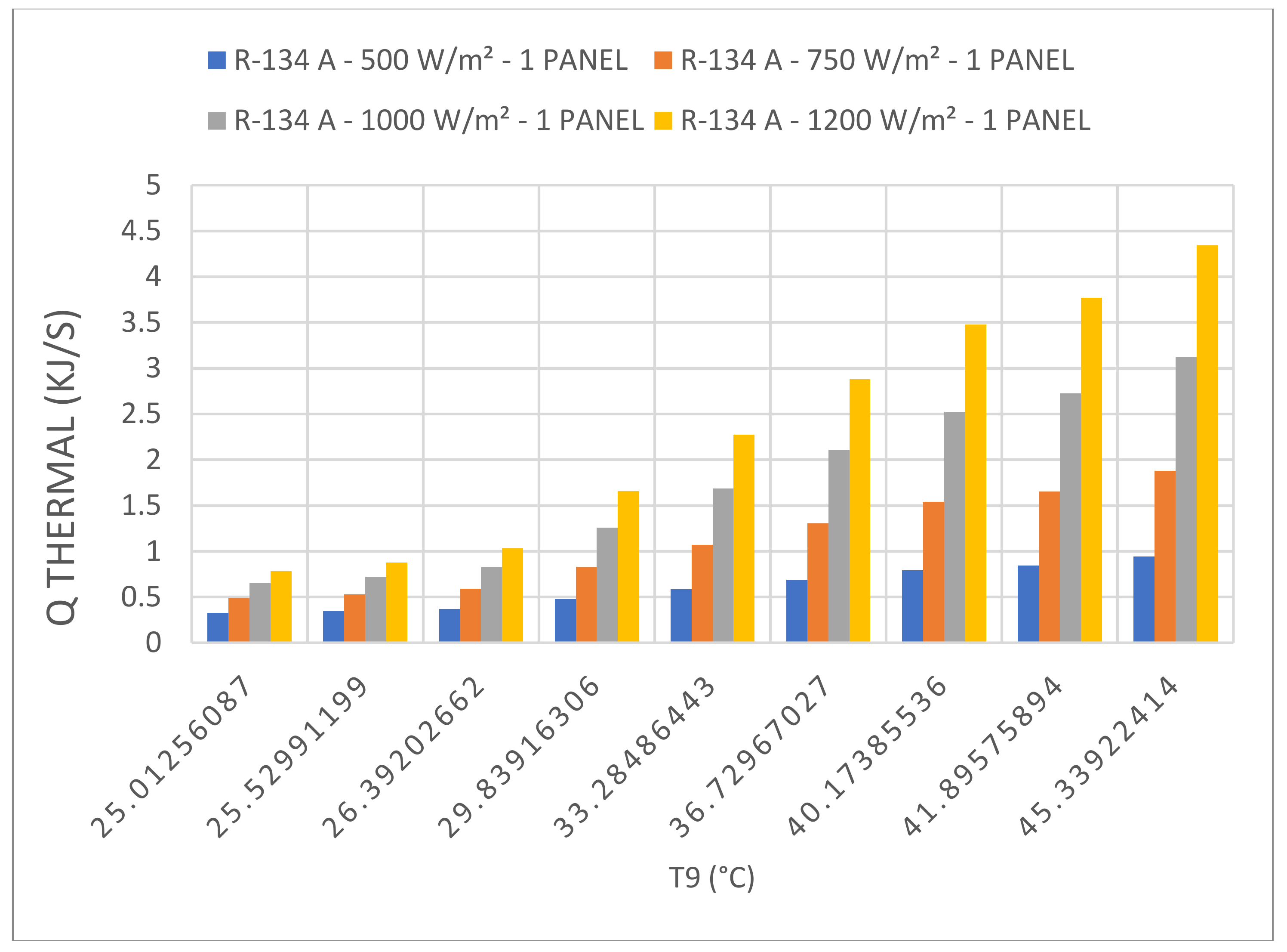
Another two important characteristics of the solar PV-thermal system are presented in Figure 14 and Figure 15; where the heat transfer fluid flow rate circulating in the thermal pipes bonded under the solar panels and the amount of thermal heat transferred from the PV solar panels to the heat transfer fluid are shown. The data presented in these figures show that the heat transfer fluid is quasi-steady and increases as the solar radiation increases. However, the results displayed in these figures also show that the thermal heat energy absorbed by the heat transfer fluid is increased slightly at higher temperatures leaving the solar collector and entering the evaporator of the heat pump with higher solar radiation. This is due to the fact that at higher solar radiation, the heat transfer fluid is heated up faster and its temperature increases at a faster rate. This thermal heat, in turn, energizes the heat pump evaporator to produce refrigerant vapor which is compressed by the compressor to higher temperatures and pressures at the condenser. The condenser cooling fluid absorbs the heat released from the condenser and delivers it to the thermal tank where the hot water is supplied for domestic or industrial use. It is worthwhile mentioning, that similar behavior was observed for the other refrigerants used in the heat pump under investigation.
Two important characteristics of the heat pump in this novel technique can be described by the compressor and condenser thermal heat capacity. Figure 16 and Figure 17 present these two important parameters, respectively.
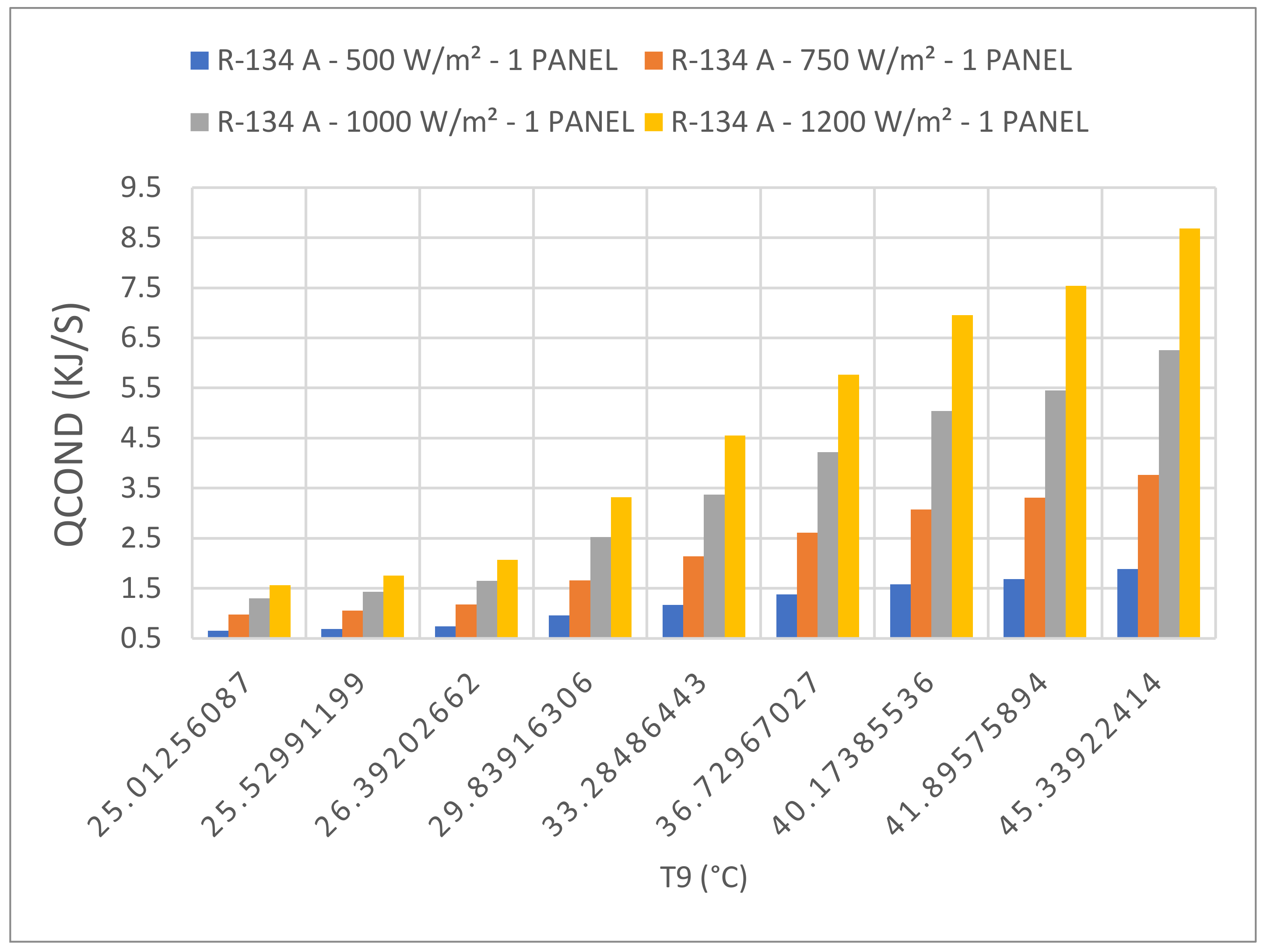
Figure 16 shows the thermal heat released from the heat pump condenser to the cooling water loop heating up the water in the thermal tank. The numerical results displayed in this figure clearly demonstrate that the higher the solar radiation, the higher the heat released by the condenser and consequently the higher the temperature of the water in the thermal tank.
The heat pump compressor power presented in Figure 17 at different solar radiation for refrigerant R-134a clearly shows that the higher the solar radiation, the higher the compressor power. This is attributed to the fact that the higher the solar radiation, the higher the evaporator temperature, which requires more thermal pumping energy by the compressor. It is worthwhile mentioning, that other refrigerants under investigation in this study showed similar behavior. This will be discussed later in this paper.
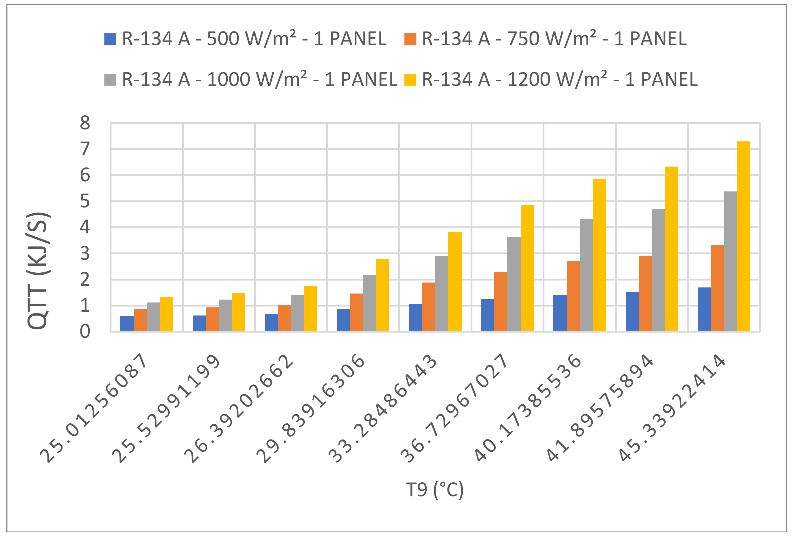
The thermal heat released by the heat pump condenser to the thermal tank for domestic or industrial use is plotted in Figure 18 at different solar radiations and R-134a. It is evident from the data displayed in this figure that the thermal heat delivered for domestic or industrial use is significantly impacted by the solar radiation and the temperature of the heat transfer fluid leaving the solar collector. The higher the solar radiation, the higher the temperature leaving the solar collector, the higher the thermal heat delivered from the thermal tank. Other refrigerants under investigation in this study showed similar behavior.
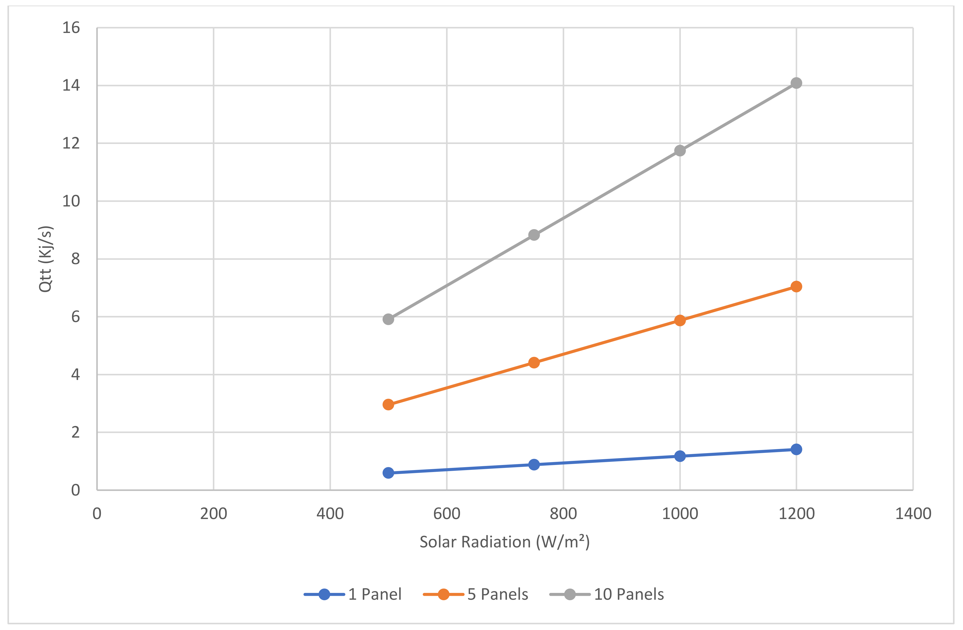
Comparison between the results presented in Figure 19 for one, five and ten PV solar panels clearly shows that increasing the number of PV solar panels is very beneficial to increase not just the electric power but also the thermal heat delivered from the thermal tank for further use.
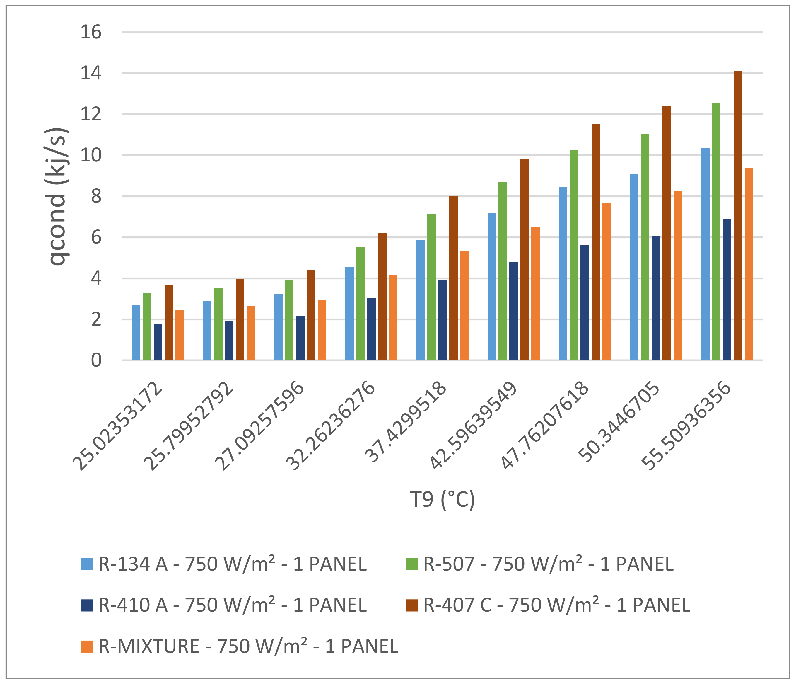
Figure 20 presents the impact of the different refrigerants under investigation on the thermal heat released by the heat pump condenser with one solar PV panel at 750 W/m2 solar radiation. As previously discussed, this thermal heat is an important parameter in determining the amount of thermal heat released from the solar collector and used to heat up the water in the thermal tank for further use. It is clear from the data displayed in this figure that this heat is significantly impacted by the characteristics of the heat pump and the type of refrigerant circulating in the vapor compression cycle of the heat pump. This illustrative figure shows that the higher the boiling point of the refrigerants the higher the heat released by the condenser. In addition, also the higher the temperature entering the evaporator, the higher the heat released by the condenser. This is one of the most important features of using a heat pump where the thermal heat absorbed in the evaporator is compressed to higher temperatures and pressures on the condenser side. The data displayed in the figure also shows that the higher the temperature, which result from higher solar radiation, entering the evaporator, the higher the pressure and temperature of the refrigerant at the condenser.
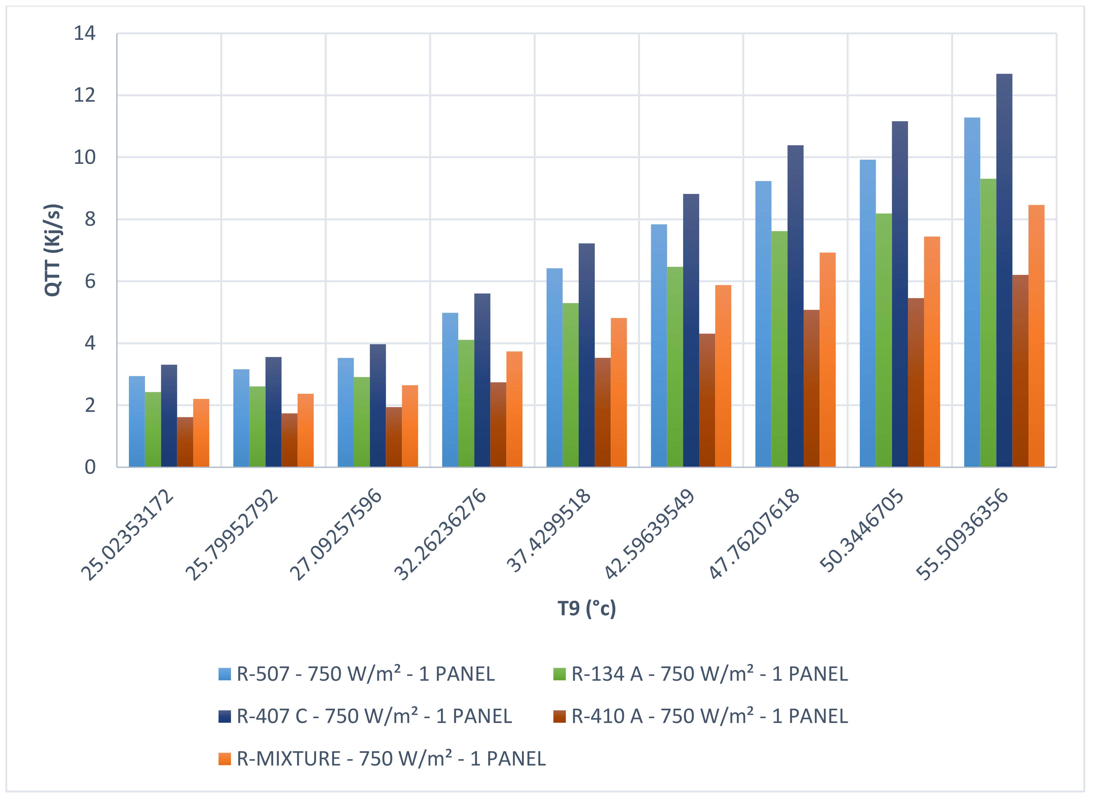
As displayed in Figure 1, the thermal heat released from the thermal tank generated by one solar PV panel for further use is presented in Figure 21 for solar radiation of 750 W/m2 and the different refrigerants under investigation. This figure clearly shows that among the refrigerants under investigation, R-407C displayed the highest amount of thermal energy delivered by the thermal tank. This is significant, and it is recommended that R-407C be used in heat pumps for this application. This figure also shows similar trends to that of the thermal heat released by the condenser. However, any difference can be attributed to the heat losses in the heat transfer process and the thermal tank, as confirmed by [33].
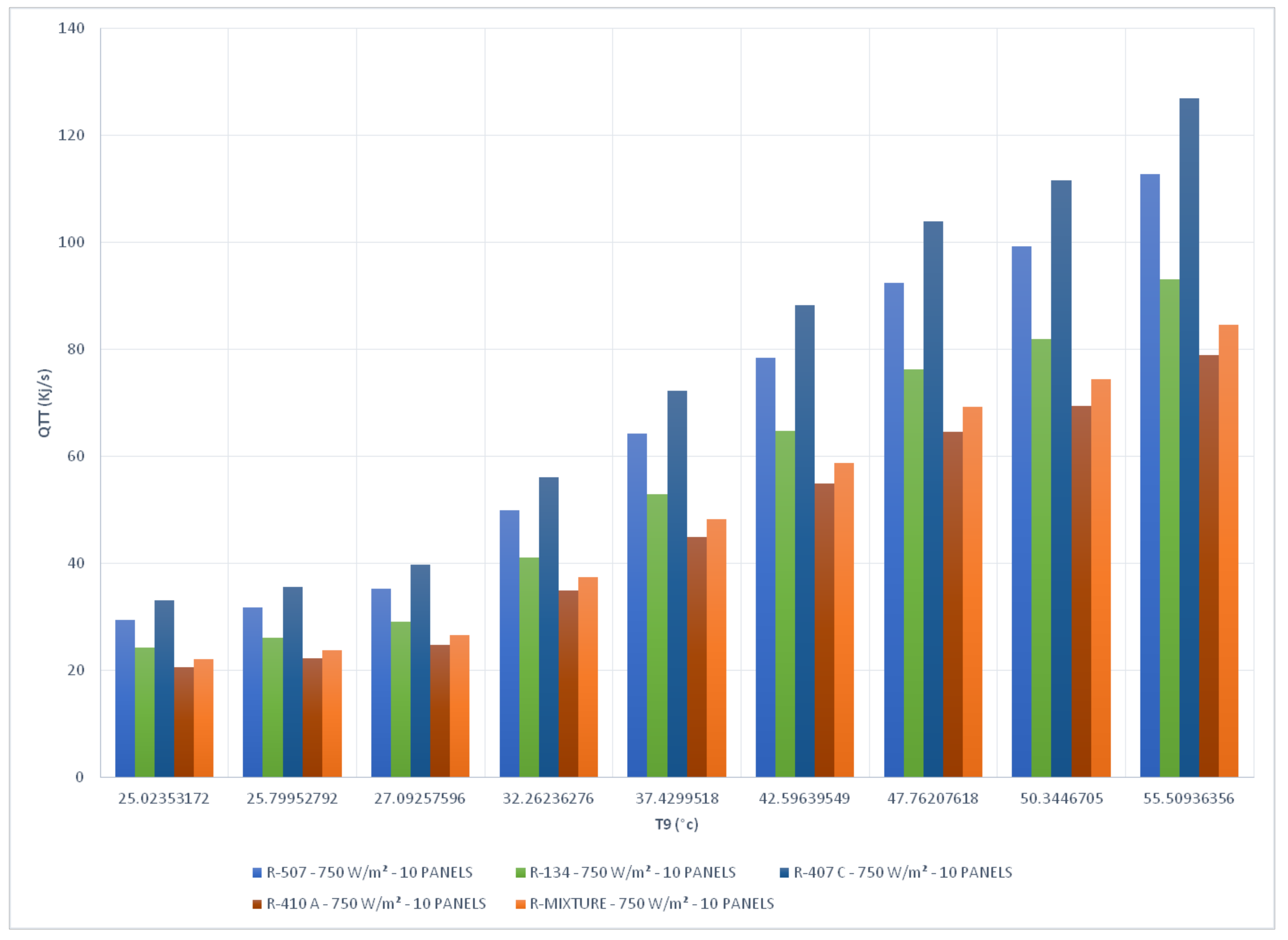
Furthermore, in order to appreciate the impact of the number of solar PV panels, Figure 22 shows the thermal heat released by the thermal tank generated by 10 solar panels at 750 solar radiation W/m2 and with different refrigerants. The data presented in this figure also shows similar trends to those displayed in Figure 21 and to that of the thermal heat released by the condenser.
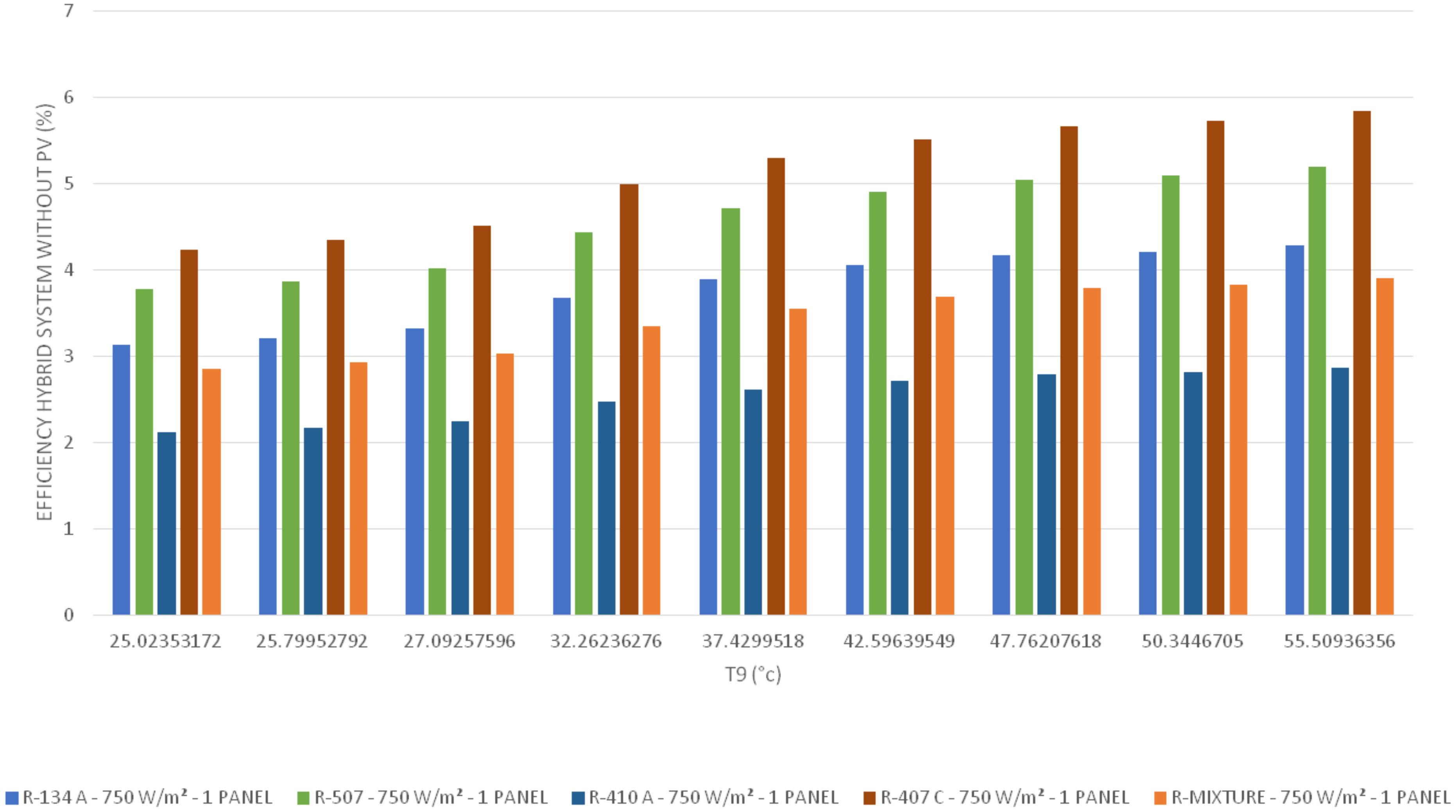
Equations (26) and (27) were used to calculate the hybrid system efficiencies with the solar PV panels and without the solar PV panels powering the heat pump, to drive the compressor of the heat pump. It is assumed in this study that when the heat pump is powered by the grid, solar PV panels are not used and only produce electricity. The results were plotted in Figure 23 and Figure 24 for the different refrigerants under investigation and solar radiation of 750 W/m2. The climatic parameters, such as solar radiation, ambient temperature, humidity and wind speed were used to calculate the efficiencies presented in these figures. The performance of the hybrid PV/T heat pump was determined in terms of thermal efficiency, PV efficiency, and electric PV efficiency. In addition, the hybrid system efficiency plotted and presented in the previous sections are also a function of the solar radiation at the site location.
It should be noted that the hybrid system efficiency is defined as the amount of electrical power and thermal energy released at the thermal tank side for further use, divided by the solar radiation. It is evident from Figure 23 and Figure 24 that the hybrid system efficiencies are significantly higher when PV solar panels were used to power the heat pump compressor compared to the grid powered compressor. In addition, the data displayed in these figures also demonstrated that the refrigerant R-407C yields the maximum efficiency of the hybrid system compared to the other refrigerants under investigation. This is attributed to the fact that the characteristics, the temperature range of application and thermodynamic properties of R-407C are the main drivers behind the high efficiency of the hybrid system using the heat pump.
Furthermore, as the aforementioned discussion illustrates, it is imperative for the designer of the PV-T integrated heat pump to ensure that the PV solar panel characteristics and cell temperatures, solar radiation at the site, the ambient conditions and the refrigerant characteristics and thermodynamic properties are taken into consideration.
9. Model Validation
In order to validate the numerical model prediction described in Equations (1)–(29) the only data available was for the solar PV panel. No data was available for the new concept presented here, that is, a fully integrated hybrid system with the heat pump. Furthermore, the basic prediction of the model performance is based upon the determination of the PV solar panel cell temperatures and heat dissipated from the solar panel. Therefore, it was felt that the PV solar model validation should show strong confidence in the results predicted herein. In addition, the model development presented is an extension of the solar PV model and the solar PV-Thermal model [30].
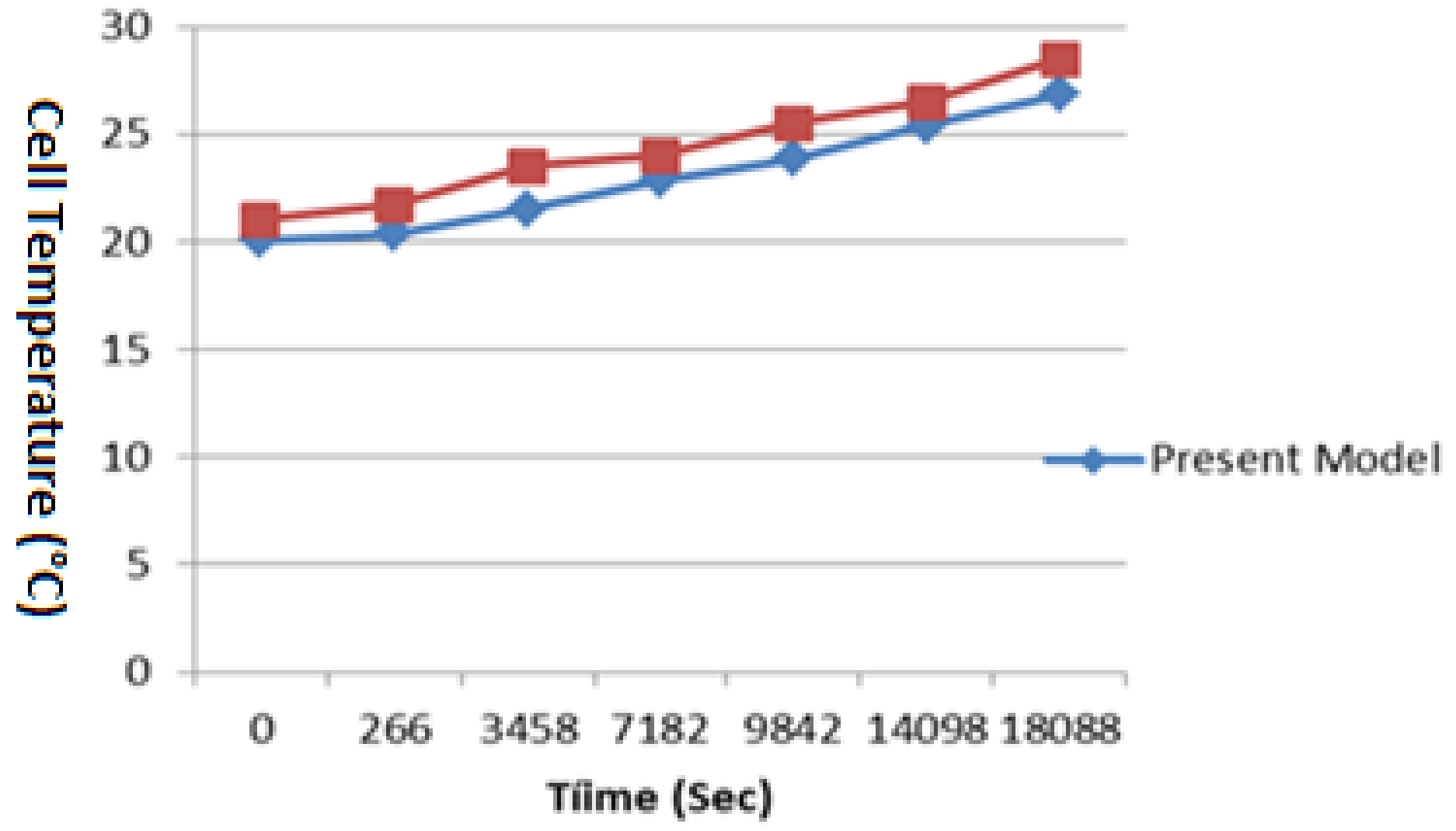
Therefore, we constructed Figure 25 and Figure 26 to compare the proposed model’s predicted numerical results for PV solar panel parameters with the data presented in the literature on the solar PV, namely, [22,30,31].
In particular, as Figure 25 shows, it is apparent from the comparison presented in the figure that the model prediction compares satisfactorily with the data for the dynamic PV cell temperature presented by Fahmy et al. [22]. The comparison presented in this figure also shows that the model and data have the same trend, however, some discrepancies exit. It is believed that the discrepancies are due to the fact that Fahmy et al. [22] did not provide full disclosure of the various parameters used in Equations (23)–(33) and Rajapakse et al. [31] had to be consulted on the various missing parameters in Fahmy et al. [22]. However, as pointed out in [14,22], considering the complexity of the PV cell temperature phenomena and its thermal behavior, we feel that our model reasonably predicted the dynamic profile of the PV cell.
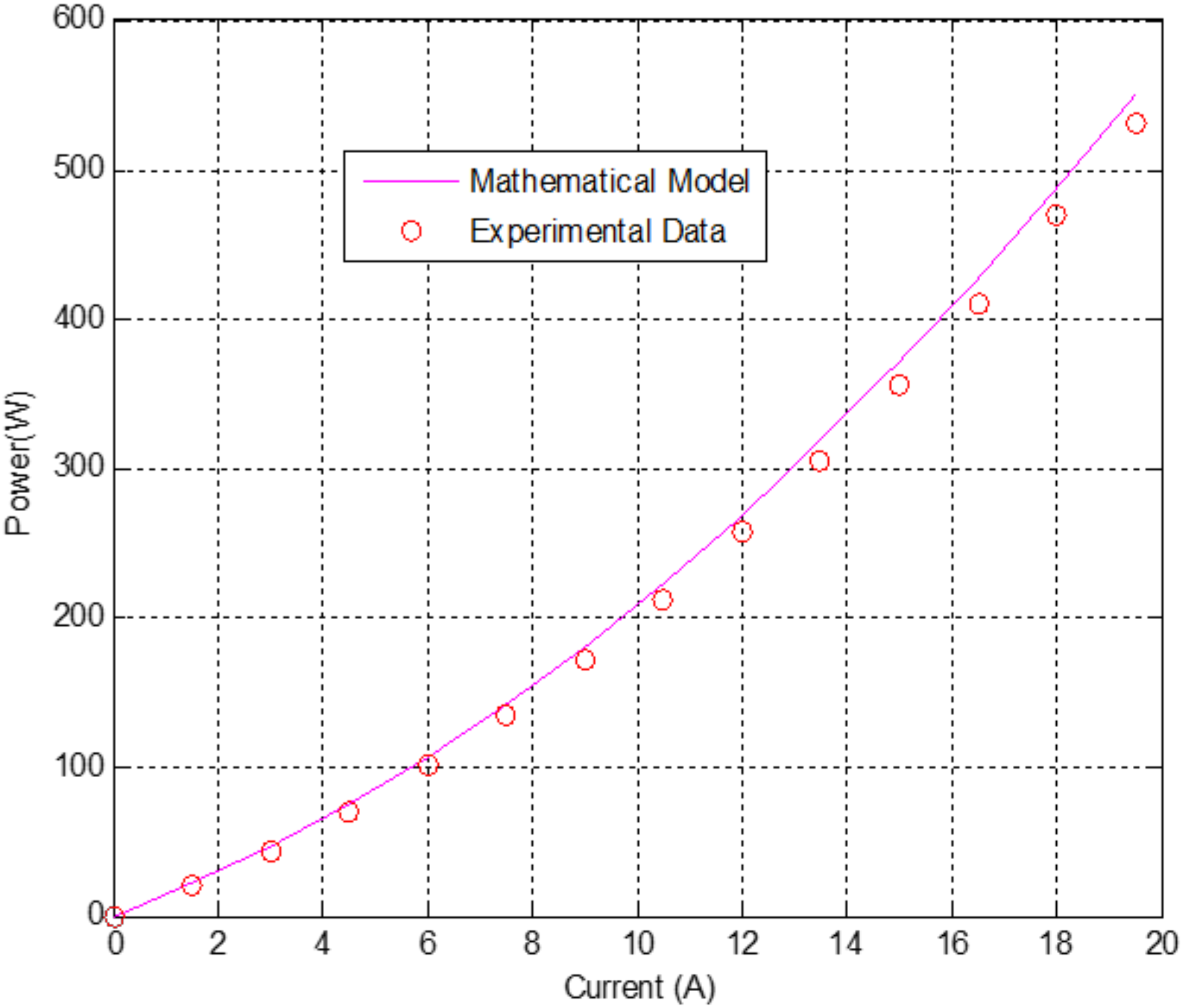
Furthermore, Figure 26 shows a comparison between model and experimental data [30,31], where the numerical prediction for the aforementioned solar PV model of the characteristics of the solar PV panel; the power at different amperage varies with solar radiation. It is evident that the present model predicted very well the solar PV characteristics. Since the present model prediction is an extension of the solar PV model and work of Sami and Campoverde [30], we feel that the current model is reliable.
10. Conclusions
Energy conversion equations describing mass and energy balance were developed, integrated, and solved to predict the dynamic total power generated, efficiencies and the key parameters of the hybrid system under investigation. The model is based on dynamic mass and energy equations coupled with the heat transfer coefficients, and thermodynamic constants as well as material properties. This hybrid system is composed of the novel combined concept of a photovoltaic-thermal solar PV panel and heat pump hybrid system. This current study investigated different solar irradiance, material properties, and boundary conditions for the solar PV panel as well as the heat pump with different refrigerants such as R-134a, R-410A, R-407C, R-507 and a mixture of the aforementioned refrigerants.
As PV solar panel efficiency calculations showed, the higher the solar radiation, the higher solar PV current and consequently this increases the solar PV power output, however, the PV solar panel efficiency remains constant at 22.38%.
It is clear from the results presented in this study that the higher the solar radiation the higher the evaporator entering temperatures, the higher the thermal heat transferred to the heat pump evaporator and the higher the heat released from the heat pump condenser. Consequently, the data also shows that the higher the solar radiation, the higher the water temperature in the thermal tank which is supplied for domestic or industrial use.
This study also showed that the hybrid system efficiencies are significantly higher when PV solar panels were used to power the heat pump compressor compared to the grid powered compressor. In addition, the data presented also demonstrated that the refrigerant R-407C yields the maximum efficiency of the hybrid system compared to the other refrigerants under investigation.
It is evident that the present model predicted very well the solar PV characteristics. Since the present model prediction is an extension of the solar PV model previously investigated by the author, we feel that the current model is reliable.
Funding
This research work received no external funding.
Acknowledgments
The research work presented in this paper was made possible through the support of the Catholic University of Cuenca. The author also would like to thank Edwin Marin for his great help in performing the different computations.
Conflicts of Interest
The author declares no conflict of interest.
Nomenclature
| Areacell | PV cell area (m2) |
| Areapipe | Pipe area (m2) |
| AreaHT | Heat transfer area (m2) |
| Cp_water | Thermal capacity of water (J/kgK) |
| COP | Coefficient of Performance |
| D | Internal Pipe diameter (m) |
| EgO | Bandgap energy of semiconductor (1.1 eV) |
| G | Total Solar radiation incident on the PV module (W/m2) |
| H | Convective heat transfer coefficient module (W/m2K) |
| hwater | Heat transfer coefficient (W/m2K) |
| h | Refrigerant enthalpy (kj/kg) |
| I | Output current of the PV module (A) |
| Io | Diode saturation current per module (A) |
| Iph | Light generated current per module or photocurrent (A) |
| Irs | Module reverse saturation current (A) |
| Isc | Short circuit current (A) |
| K | Boltzmann’s constant (1.3806503 × 10⁻²³ J/K) |
| Ki | Short-circuit of a PV cell at SRC (mA/°C) |
| KPv | Thermal conductivity of PV cell (W/mK) |
| Lcell | Length of a PV cell (m) |
| ṁ | Water flow (Kg/s) |
| mCp_module | Thermal capacity of the PV module (9250 J/K) |
| mwater | mass of water (Kg) |
| n | Ideality factor of the diode (q) |
| Np | Total number of cells connected in parallel |
| Npipe | Number of pipes |
| Ns | Total number of cells connected in series |
| nTE | number of Thermal Elements in a pipe |
| P | Power generated by PV module (W) |
| Pa | Atmospheric pressure of moist air (Pa) |
| pw | Partial pressure of water vapor in moist air (Pa) |
| q | Electronic charge (C) |
| Qconduction | Energy due to conduction (W in Electrical Process) (W/m2 in Thermal Process) |
| Qconvection | Energy due to convection (W in Electrical Process) (W/m2 in Thermal Process) |
| Qelect | Electrical power generated (W) |
| Qin | Energy received due to Solar irradiation (W/m2) |
| Qin_cell | Energy incident on one PV cell due to solar radiation (W/m2) |
| Qradiation | Energy due to radiation (W/m2 in Thermal Process) |
| QThermal | Energy from thermal process (W) |
| Rs | Diode series resistance per module (Ω) |
| Rsh | Diode shunt resistance per module (Ω) |
| Sc | Total surface area of PV cells in a module (m2) |
| Sp | Total area of the PV module (m2) |
| T | Operating temperature (k) |
| T | Time (s) |
| Ta | Ambient temperature (°C) |
| TC | PV Cell Temperature (°C) |
| Tdb | Dry bulb temperature (°C) |
| Tf | Fluid temperature (°C) |
| Tf | Fluid temperature (°C) |
| Tf_in | Fluid temperature at inlet (°C) |
| TfHx | Maximum temperature at the Heat Exchanger(°C) |
| TfHx+1 | Fluid temperature at thermal element 1 (dx) (°C) |
| Tm | Module Back-surface temperature(°C) |
| Tr | Nominal temperature (298.15 K) |
| U | Thermal conductance of clean heat exchanger (W/m2K) |
| Ud | Thermal conductance of heat exchanger after fouling (W/m2K) |
| V | Output voltage (V) |
| Voc | Open circuit voltage (V) |
| Vt | Diode thermal voltage (V) |
| x | Humidity ratio (kgwater/kgdry_air) |
| αabs | Overall absorption coefficient |
| ηHybrid | Hybrid system efficiency |
| ηPv | PV module efficiency |
| ηThermal | Efficiency of thermal process |
| ρw | Density of water vapor (Kg/m3) |
| Convection heat transfer rate | |
| Q | Thermal heat (kj/s) |
| Emissivity PV cell | |
| Re | Reynolds number |
References
- Yang, D.J.; Yuan, Z.F.; Lee, P.H.; Yin, H.M. Simulation and experimental validation of heat transfer in a novel hybrid solar panel. Int. J. Heat Mass Transf. 2012, 55, 1076–1082. [Google Scholar] [CrossRef]
- Calise, F.; Venoli, L. Paraboloc through Photovoltaic/Thermal Collectors: Design and Simulation Model. Energies 2012, 5, 4186–4208. [Google Scholar] [CrossRef]
- Jakhar, S.; Sonu, M.S.; Gakkhar, N. Modeling and Simulation of Concentrating Photovoltaic with Earth Water Heat Exchanger Cooling. Energ. Procedia 2017, 109, 78–85. [Google Scholar] [CrossRef]
- Dai, N.; Li, S.; Zhang, Z. Simulation of Hybrid Photovoltaic Solar Assisted Loop Heat Pipe/Heat Pump System. Appl. Sci. 2017, 7, 197. [Google Scholar] [CrossRef]
- Lalovi, B.; Kiss, Z.; Weakliem, H.A. hybrid amorphous silicon photovoltaic and thermal solar-collector. Sol. Cells 1986, 19, 131–138. [Google Scholar] [CrossRef]
- Tripanagnostopoulos, Y.; Nousia, T.; Souliotis, M.; Yianoulis, P. Hybrid photovoltaic/thermal solar systems. Sol. Energy 2002, 72, 217–234. [Google Scholar] [CrossRef]
- Bergene, T.; Lovvik, O.M. Model calculations on a flat-plate solar Heat-collector with integrated solar cells. Sol. Energy 1995, 55, 453–462. [Google Scholar] [CrossRef]
- Teo, H.G.; Lee, P.S.; Hawlader, M.N.A. An active cooling system for photovoltaic modules. Appl. Energy 2012, 90, 309–315. [Google Scholar] [CrossRef]
- Wang, E.; Fung, A.S.; Qi, C.; Leong, W.H. Build-up and long-term performance prediction of a hybrid solarground source heat pump system for office building in cold climate. In Proceedings of the eSim 2012: The Canadian Conference on Building Simulation, Halifax, NS, Canada, 1–4 May 2012. [Google Scholar]
- Hashim, H.; Bomphrey, J.J.; Min, G. Model for Geometry Optimization of Thermoelectric Devices in a Hybrid PV/TE System. Renew. Energy 2016, 87, 458–463. [Google Scholar] [CrossRef]
- Chen, H.; Riffat, S.B.; Fu, Y. Experimental study on a hybrid photovoltaic/heat pump system. Appl. Therm. Eng. 2011, 31, 4132–4138. [Google Scholar] [CrossRef]
- Garge, H.P.; Agarwal, R.K. Some aspects of a PV/T collector/force Circulation flat-plate solar water heater with solar cells. Energy Convers. Manag. 1995, 36, 87–99. [Google Scholar] [CrossRef]
- Huang, B.J.; Du, S.C. A performance test method for solar thermosyphon-systems. ASME J. Sol. Energy Eng. 1991, 113, 172–179. [Google Scholar] [CrossRef]
- Sandnes, B.; Rekstad, J. A photovoltaic/thermal (PV/T) collector with a polymer absorber plate, experimental study and analytical model. Sol. Energy 2002, 72, 63–73. [Google Scholar] [CrossRef]
- Badescu, V. First and second law analysis of a solar assisted heat pump based heating system. Energy Convers. Manag. 2002, 43, 2539–2552. [Google Scholar] [CrossRef]
- Noro, M.; Lazzarin, R.M. Hybrid PhotoVoltaic- Thermal heat pump systems: Energy and economic performance evaluations in different climates. Int. J. Low-Carbon Technol. 2018, 13, 76–83. [Google Scholar] [CrossRef]
- Ito, S.; Miura, N.; Wang, J.Q.; Nishikawa, M. Heat pump using a solar collector with photovoltaic modules on the surface. J. Sol. Energy Eng. 1997, 119, 147–151. [Google Scholar] [CrossRef]
- Sami, S.; Marin, E. Simulation of Solar Photovoltaic, Biomass Gas Turbine and District Heating Hybrid System. Int. J. Sustain. Energy Environ. Res. IJSEER 2017, 6, 9–26. [Google Scholar] [Green Version]
- Sami, S.; Rivera, J. A Predictive Numerical Model for Analyzing Performance of Solar Photovoltaic, Geothermal Hybrid System for Electricity Generation and District Heating. Sci. J. Energy Eng. SJEE 2017, 5, 13–30. [Google Scholar] [CrossRef]
- Sami, S.; Marin, E. A Numerical Model for Predicting Performance of Solar Photovoltaic, Biomass and CHP Hybrid system for Electricity Generation. IJESRT Int. J. Eng. Sci. Res. Technol. 2017, 4, 1–22. [Google Scholar]
- Good, C.; Chen, J.; Dai, Y.; Hestnes, A.G. Hybrid Photovoltaic-Thermal system: A Review. Energy Procedia 2015, 70, 683–690. [Google Scholar] [CrossRef]
- Fahmy, F.H.; Nafeh, A.A.; Ahamed, N.M.; Farghally, H.M. A Simulation Model for Predicting the Performance of PV/Wind- Powered Geothermal Space Heating System in Egypt. In Proceedings of the International Conference on Renewable Energies and Power Quality (ICREPQ’10), Granada, Spain, 23–25 March 2010. [Google Scholar] [CrossRef]
- Sami, S.; Tulej, P. A new design for an air-source heat pump using ternary mixture for cold climate. Heat Recov. Syst. CHP 1995, 15, 521–529. [Google Scholar] [CrossRef]
- Humidity—Wikipedia. Available online: https://en.wikipedia.org/wiki/Humidity (accessed on 10 June 2018).
- Engineering Toolbox. Water Vapor and Saturation Pressure in Humid Air. 2004. Available online: http://www.engineeringtoolbox.com/water-vapor-saturation-pressure-air-d_689.html (accessed on 10 June 2018).
- Duffie, J.A.; Beckman, W.A. Solar Engineering of Thermal Process; Wiley: New York, NY, USA, 1991. [Google Scholar]
- Engineering Toolbox. Fouling and Reduced Heat Transfer in Heat Exchangers. 2010. Available online: http://www.engineeringtoolbox.com/fouling-heat-transfer-d_1661.html (accessed on 10 June 2018).
- Armstrong, S.; Hurley, W.G. A thermal model for photovoltaic panels under varying atmospheric conditions. Appl. Therm. Eng. 2010, 30, 1488–1495. [Google Scholar] [CrossRef]
- Fontenault, B.J.; Gutierrez-Miravete, E. Modeling a Combined Photovoltaic-Thermal Solar Panel. In Proceedings of the 2012 COMSOL Conference in Boston, Boston, MA, USA, 15 March 2012. [Google Scholar]
- Sami, S.; Campoverde, C. Dynamic Simulation and Modeling of a Novel Combined Photovoltaic–Thermal Panel Hybrid System. Int. J. Sustain. Energy Environ. Res. 2018, 7, 1–23. [Google Scholar] [CrossRef]
- Rajapakse, A.; Chungpaibulpantana, S. Dynamic simulation of a photovoltaic refrigeration system. RERIC 1994, 16, 67–101. [Google Scholar]
- NIST. Available online: http://www.boulder.nist.gov/div838/theory/refprop/LINKING/Linking.htm#ExcelApplications (accessed on 10 June 2018).
- Glembin, J.; Büttner, C.; Steinweg, J.; Rockendorf, G. Thermal Storage Tanks in High Efficiency Heat Pump Systems—Optimized Installation and Operation Parameters. Energy Procedia 2015, 73, 331–340. [Google Scholar] [CrossRef]
Figure 1.
Photovoltaic/thermal (PV/T)-heat pump hybrid system.

Figure 2.
Logical flow diagram.

Figure 3.
Ambient temperatures (°C) profile 2015–2016.

Figure 4.
Solar irradiances (W/m2). Profile 2015–2016.

Figure 5.
Cell temperature at different solar radiations (W/m2) and temperature difference 15 °C.

Figure 6.
Back PV cell temperature at different solar radiation (W/m2) and heat exchanger temperature difference of 15 °C.
Figure 6.
Back PV cell temperature at different solar radiation (W/m2) and heat exchanger temperature difference of 15 °C.

Figure 7.
Fluid temperature exiting the thermal pipes at a heat exchanger temperature difference of 15 °C and different solar radiation (W/m2).
Figure 7.
Fluid temperature exiting the thermal pipes at a heat exchanger temperature difference of 15 °C and different solar radiation (W/m2).

Figure 8.
Heat released by single cell at different solar radiation (W/m2) at one solar PV panel and a heat exchanger temperature difference of 15 °C.
Figure 8.
Heat released by single cell at different solar radiation (W/m2) at one solar PV panel and a heat exchanger temperature difference of 15 °C.

Figure 9.
Heat transfer fluid at different solar radiation (W/m2) for one solar PV panel.

Figure 10.
Thermal system efficiency at different solar radiation (W/m2) and a heat exchanger temperature difference of 15 °C.
Figure 10.
Thermal system efficiency at different solar radiation (W/m2) and a heat exchanger temperature difference of 15 °C.

Figure 11.
Thermal heat transfer to the heat pump evaporator for one solar PV panel.

Figure 12.
Heat pump heat released by the condenser at different solar radiation and refrigerant R-134a.
Figure 12.
Heat pump heat released by the condenser at different solar radiation and refrigerant R-134a.

Figure 13.
Power generated by solar PV panel with refrigerant R-134a.

Figure 14.
Heat transfer fluid circulating in PV/Thermal pipe with refrigerant R-134a.

Figure 15.
Thermal heat transferred at different solar radiations with R-134a to the heat transfer fluid.
Figure 15.
Thermal heat transferred at different solar radiations with R-134a to the heat transfer fluid.

Figure 16.
Thermal heat released by the heat pump condenser at different solar radiation with R-134a.
Figure 16.
Thermal heat released by the heat pump condenser at different solar radiation with R-134a.

Figure 17.
The heat pump compressor power at different solar radiation for refrigerant R-134 a.

Figure 18.
Thermal heat released by the thermal tank for domestic or industrial use at different solar radiation and R-134a.
Figure 18.
Thermal heat released by the thermal tank for domestic or industrial use at different solar radiation and R-134a.

Figure 19.
Thermal heat released by the thermal tank for domestic or industrial use at different solar radiation, 25 °C entering evaporator temperature and R-134a.
Figure 19.
Thermal heat released by the thermal tank for domestic or industrial use at different solar radiation, 25 °C entering evaporator temperature and R-134a.

Figure 20.
Thermal heat released by the heat pump condenser with one solar PV panel at different solar radiation and different refrigerants.
Figure 20.
Thermal heat released by the heat pump condenser with one solar PV panel at different solar radiation and different refrigerants.

Figure 21.
Thermal heat released by the thermal tank for further use by one panel at 750 W/m2 solar radiation and different refrigerants.
Figure 21.
Thermal heat released by the thermal tank for further use by one panel at 750 W/m2 solar radiation and different refrigerants.

Figure 22.
Thermal heat released by the thermal tank for further use at 750 W/m2 solar radiation and different refrigerants for 10 panels.
Figure 22.
Thermal heat released by the thermal tank for further use at 750 W/m2 solar radiation and different refrigerants for 10 panels.

Figure 23.
Hybrid system efficiencies with the solar PV panels powering the heat pump.

Figure 24.
Hybrid system efficiencies with powering the heat pump with the grid.


© 2018 by the author. Licensee MDPI, Basel, Switzerland. This article is an open access article distributed under the terms and conditions of the Creative Commons Attribution (CC BY) license (http://creativecommons.org/licenses/by/4.0/).
Share and Cite
MDPI and ACS Style
Sami, S. Modeling and Simulation of a Novel Combined Solar Photovoltaic-Thermal Panel and Heat Pump Hybrid System. Clean Technol. 2019, 1, 89-113. https://doi.org/10.3390/cleantechnol1010007
AMA Style
Sami S. Modeling and Simulation of a Novel Combined Solar Photovoltaic-Thermal Panel and Heat Pump Hybrid System. Clean Technologies. 2019; 1(1):89-113. https://doi.org/10.3390/cleantechnol1010007
Chicago/Turabian StyleSami, Samuel. 2019. "Modeling and Simulation of a Novel Combined Solar Photovoltaic-Thermal Panel and Heat Pump Hybrid System" Clean Technologies 1, no. 1: 89-113. https://doi.org/10.3390/cleantechnol1010007