Siloxane Precursor-Based Protective Coatings for High Modulus Carbon Fibers in Ceramic Matrix Composites


1
Institut für Fertigungstechnologie keramischer Bauteile, Universität Stuttgart, Allmandring 7b, D-70569 Stuttgart, Germany
2
Institut für Materialwissenschaft, Universität Stuttgart, Heisenbergstr. 3, D-70569 Stuttgart, Germany
*
Author to whom correspondence should be addressed.
Ceramics 2018, 1(1), 128-138; https://doi.org/10.3390/ceramics1010011
Submission received: 15 May 2018
/
Revised: 20 July 2018
/
Accepted: 24 July 2018
/
Published: 26 July 2018
(This article belongs to the Special Issue Advances in the Field of Nanostructured Ceramic Composites)
Abstract
:Carbon fibers are outstanding reinforcements for ceramic components due to their excellent creep and long-term thermochemical and thermomechanical stability. Nevertheless, these properties are dramatically downgraded if the unprotected fibers are exposed to an oxidative or corrosive environment. Thin ceramic coatings can improve the corrosion resistance and tailor the fiber/matrix interface in order to achieve optimized stress transfer and damage tolerance. The continuous liquid phase coating (CLPC) technique with subsequent pyrolysis is a promising alternative to chemical vapor deposition (CVD) processes. The possibility to deposit homogenous thin flaw-free coating layers on every filament of high tenacity carbon fiber bundles has been successfully proven in previous studies. In this work, high modulus carbon fibers were coated with different polysiloxane-based resins, and the obtained rovings were implemented in SiOC matrices by the precursor impregnation and pyrolysis (PIP) route. Thermogravimetric analysis shows an increased oxidation resistance of the coated fibers compared with reference samples. Enhanced fiber/matrix interface strength further improved the mechanical performance of the fabricated composites.
1. Introduction
The superior mechanical and tribological performance qualifies ceramic matrix composites (CMC) for high-temperature applications in aerospace and automotive sectors [1,2,3]. This material class combines the properties of monolithic ceramics such as high stiffness, chemical inertness, and low density, with enhanced toughness and improved resistance to thermal shock [4]. Its non-catastrophic mode of failure is attributed to different energy dissipation phenomena, such as pull-out (frictional dissipation), crack deflection, crack bridging, and fiber debonding [5,6].
Carbon fibers are a reinforcement of special interest due to their remarkable strength and stiffness at high temperatures and affordable costs. However, these properties cannot be sustained if they are exposed to an oxidative atmosphere. Carbon-based composites show significant degradation in air above 400 °C. This is an important limiting factor for their introduction as high-temperature lightweight structural components in the aerospace industry, such as aircraft engine parts or thermal protection for spacecraft. For this reason, an environmental barrier coating (EBC) of an appropriate combination of refractory materials [7,8] is typically introduced in carbon fiber-reinforced ceramics. An oxidation protective fiber coating would support the role of the EBC if the composite is damaged and oxygen can penetrate into the bulk by voids formed. The fiber coating would prevent fiber oxidation for the time until the self-healing mechanism of the EBC is finished. Thus, a protection of the carbon filaments against oxidation is necessary for harsh service environments.
Additionally, the damage tolerance of fiber-reinforced ceramic composites is highly dependent on the strength of the fiber as well as on the fiber/matrix interface. Two micromechanical approaches have been developed [9] to describe the material behavior in a macroscopic way. The first microstructural group is called weak interface composites (WIC). In this group, crack deflection is achieved by weakening of the fiber/matrix interface. Under applied tensile stress, cracks are initially formed in the matrix and propagate toward the fibers. A weak interface between the matrix and fibers allows debonding of these two components, which facilitates sliding of the fibers and eventually leads to the enhanced toughness of the composite [1,10]. This behavior is normally seen in dense and highly crystallized CMCs such as CVI-derived (Chemical Vapor Infiltration) SiC–matrix composites [9]. On the other hand, composites manufactured by infiltration techniques, such as precursor impregnation and pyrolysis (PIP), have a finely porous microstructure that results in lower stiffness and strength. The weak nature of the matrix allows multiple cracking of this component which leads to crack deviation close to the fiber surface, facilitating debonding and sliding processes. This group of composites is known as weak matrix composites (WMC) [9]. The above-mentioned concepts describe extreme cases, whereas real composites exhibit mixed failure mechanisms. In the same publication, the relative Young’s Modulus, a factor with a strong influence on the failure mechanisms of CMCs, is defined as follows:
where EF and EM are the Young’s Modulus of the fiber and the matrix, respectively. An increase of the fiber’s modulus, and therefore of the relative Young’s Modulus of the composite, situates the material closer to the non-brittle failure area of weak matrix composites at the boundary curve. For this reason, the selection of high modulus, instead of high tenacity, carbon fibers can potentially improve the toughness of the CMCs.
The optimization of the fiber/matrix interface can be also conducted by fiber treatments. The preferred method is the application of a ceramic layer on the surface of the fibers. State-of-the-art technologies to perform these fiber coatings are chemical vapor deposition (CVD) or physical vapor deposition (PVD). Relevant studies [11,12] have verified the CVD technique to deposit thin layers of TaC, TiC, TiN, TiNC, SiC, and PyC on carbon fibers optimizing fiber/matrix interfaces in ceramic and metal matrix composites. Although these techniques exhibit an excellent technical performance, they are relatively cost and time-intensive, and require high safety standards. In this study, the application of coating layers on high modulus carbon fibers was achieved by continuous liquid phase coating (CLPC). This coating technology, developed by Kern and Gadow [13,14,15], is a cost-efficient alternative to CVD and PVD techniques based on a continuous dip-coating process. It enables the deposition of dense and homogenous thin ceramic coatings on every single filament of a fiber strand from coil to coil using a preceramic polymer solution as coating solution. Due to changing the chemical composition of the preceramic precursor, a variety of coatings ranging from pure carbon to e.g., silicon carbide, silicon carbonitride, or silicon oxycarbide can be manufactured [16].
2. Materials and Methods
2.1. Fiber Coating
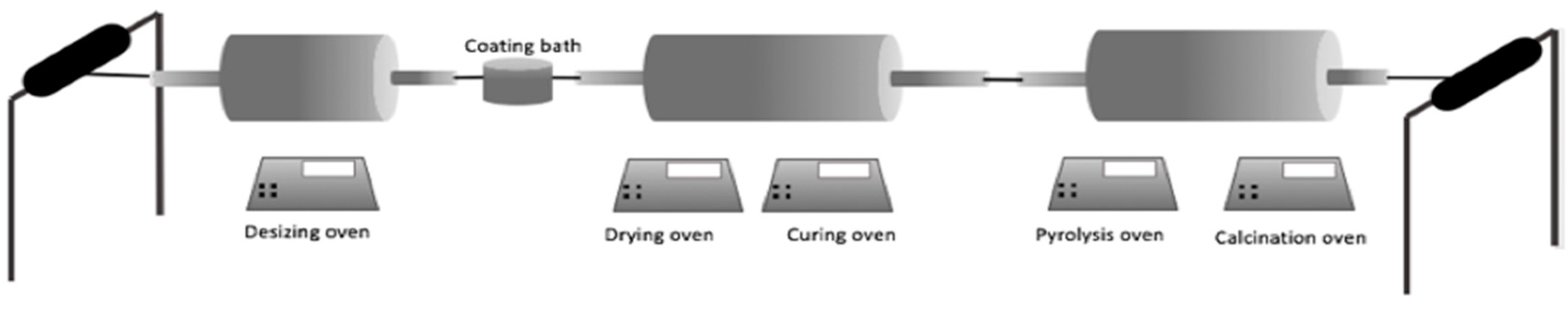
For this work, 12-K rovings of Mitsubishi K63712 pitch-based carbon fiber were used. The schematic illustration of the coating plant is shown in Figure 1. The CLPC procedure is as follows: first, the sizing agents on the commercial roving are thermally removed at 600–700 °C in a countercurrent of nitrogen or argon. Removal of the sizing is necessary to avoid the reaction of the sizing agents with the coating precursor. Secondly, the fibers are soaked in the coating bath containing the preceramic precursor dissolved in an organic solvent. Finally, the fibers are passed subsequently through four separate tube furnaces in order to complete the drying, curing, pyrolysis, and calcination processes. All of the furnaces were kept under inert atmosphere by maintaining constant nitrogen purging gas flow. With the help of thermal gravimetric analysis, the appropriate temperature level for each furnace was selected.
Table 1 shows an overview of the coating solutions employed in this study, including the names of the precursors and concentrations. Two different solvents, Isopropanol and MEK (methyl ethyl ketone), were employed for the solutions. The different concentration values are the result of previous optimization studies. Regarding previous studies of co-authors and effectuated thermogravimetric measurements (DTA-TG), the temperature program for every coated fiber was defined as follows: desizing 600 °C; drying 250 °C; curing 400 °C; and calcination 820 °C. The calcination temperature was not further increased considering the negative influence of higher calcination temperatures on the tensile strength of the carbon filaments investigated in a previous study [17]. If this temperature reaches the interval 900–1100 °C, the hardness and stiffness of the coating layers increase significantly. Below that threshold, existing fiber bridges consisting of pyrolyzed/calcined precursor can be broken during filament winding without damaging the fiber strand; above this level, the tensile strength of the filaments is impeded.
2.2. Composite Preparation
The CMC samples were manufactured by polymer impregnation and pyrolysis (PIP). Firstly, coated and reference fibers were impregnated with SILRES® H62 C resin (Wacker Chemie, Burghausen, Germany) and radially wound on a 32-cm square winding mandrel until a thickness of approximately 3 mm was achieved. The fiber reinforcement of the manufactured samples is therefore unidirectional. After that, the mandrel with the impregnated fibers was transferred into an oven and held at 180 °C under air atmosphere during four hours for the cross-linking of the resin.
After the matrix was completely cured, the composite was removed from the mandrel, and rectangular samples of 120 × 15 mm were cut and pyrolyzed at 850 °C in nitrogen atmosphere. The porosity generated in the pyrolyzed matrix by mass loss and densification during pyrolysis was re-infiltrated with SILRES® H62 C resin under vacuum and cross-linked again afterwards. This pyrolysis/re-infiltration cycle was repeated three times.
2.3. Thermogravimetric Analysis
The oxidation resistance of the coated and reference fibers was measured by simultaneous TGA/DTA tests with a NETZSCH STA 409 CD thermal analysis device under oxygen flow. The reason for selecting pure oxygen instead of air was the intention of accelerating the oxidation process of the carbon fibers. The thermal program consisted of a ramp from room temperature to 700 °C with a heating rate of 20 K/min followed by a dwell of 120 min at this temperature.
2.4. Thermal Aging Treatment
In order to analyze the influence of the coatings on the oxidation resistance of the manufactured composites, several thermal aging treatments were carried out under air atmosphere. Table 2 shows the temperature and duration of these treatments.
2.5. Flexural Strength
The influence of the coating layer and aging treatments on the flexural strength of the composites was investigated by three-point bending tests. For this purpose, a Z100 universal testing machine (Zwick GmbH & Co. KG., Ulm, Germany) was used. The flexural strengths of the composites were calculated according to the EN 658-3 standard [18]. Five samples were tested for each type of treatment.
3. Results
3.1. Optical Characterization of Fiber Coatings
The SEM images of the coated fibers prove the deposition of a thin ceramic layer on every single filament of the rovings. As shown in Figure 2, individual fibers do not stick together. In order to visualize the coatings, images were taken in spots where the coatings presented some irregularity or defect. On the remaining surfaces, the coating layers showed a homogenous, almost flawless and even structure. The coating aspect is nearly epitactic with respect to the original fiber geometry. Some debris particles resulting from broken fiber bridges while winding the fiber strands after coating are visible.
3.2. Thermogravimetric Analysis
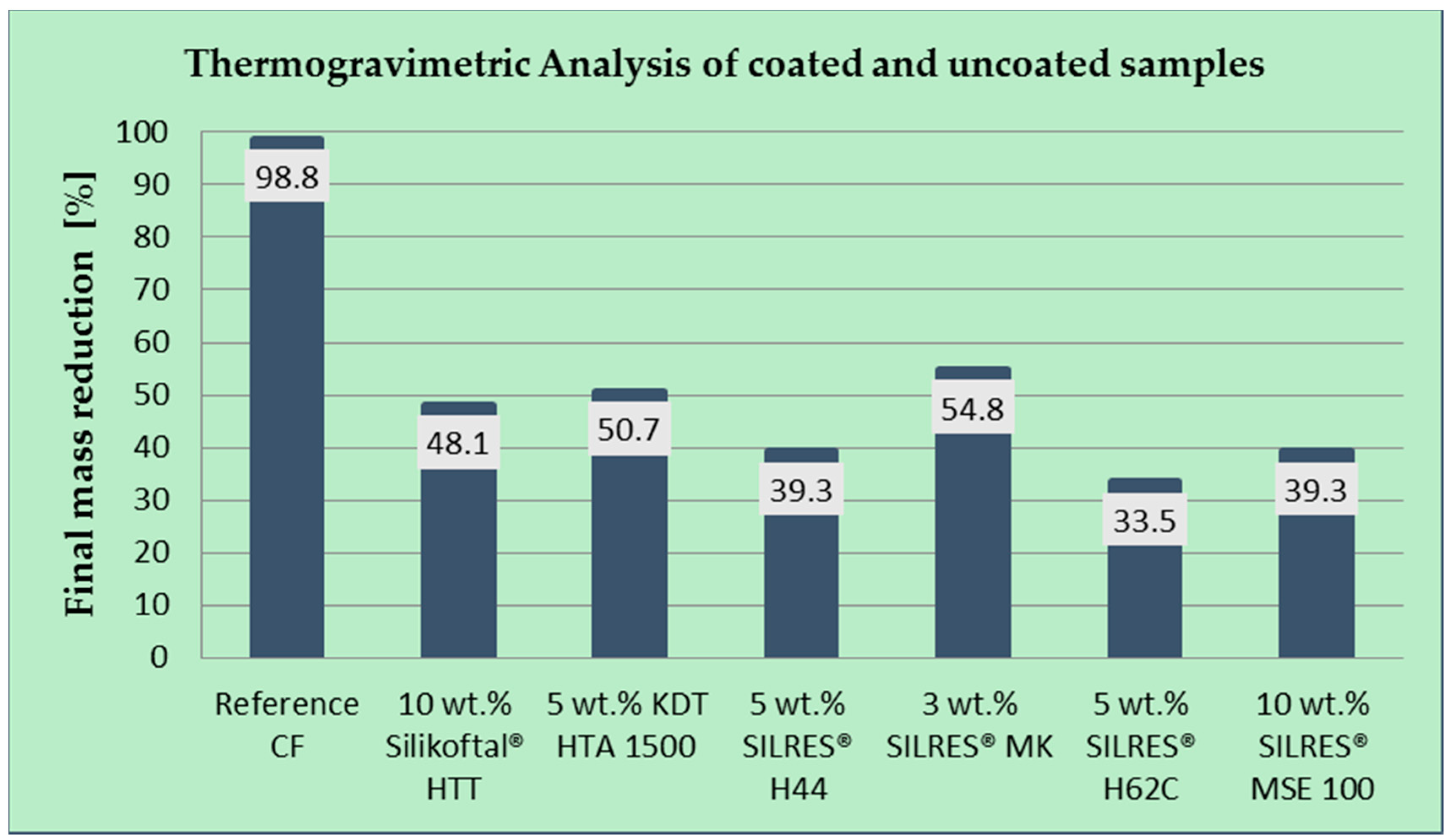
Figure 3 shows the final mass loss of the studied samples after the thermogravimetric analysis. It can be observed that the reference sample is entirely consumed during the exposure to oxygen. The final mass reduction of the untreated filaments was quantified at 98.8%, which underlines their poor oxidation resistance and justifies the application of a protecting coating. The complete DTA-TG curve of this sample is shown in Figure 4. While the DTA peaks appearing at low temperatures can be attributed to the evaporation or oxidation of the polymer sizing, the onset of mass loss for the fiber as such is observed at ~590 °C. Above 600 °C, the DTA curve shows a local maximum at 0.8 mV/mg after 50 min in the isothermal section.
As observed for the rest of the results shown in Figure 3, the different coating layers have a considerably positive effect on the oxidation resistance. The worst result was observed for the 3 wt. % SILRES® MK-coated fibers, losing the 54.8% of its mass, which in fact represents a significant improvement with respect to the reference sample. The best result was measured for the 5 wt. % SILRES® H62 C, which remains approximately 2/3 of its initial mass after the oxidative thermal treatment (mass reduction of 33.5%).
Figure 5 and Figure 6 show the DTA-TG graphics of the coatings with the best and worst oxidation protection performance (3 wt. % SILRES® MK and 5 wt. % SILRES® H62 C). In comparison with the behavior of the untreated fibers shown in Figure 4, where an exponential mass loss takes place after approximately 75 min of test, the coated fibers exhibit a linear mass loss tendency during the whole dwelling at 700 °C.
The samples were analyzed after the DTA-TG tests by means of scanning electron microscopy. In Figure 7a, it can be observed that the remaining 1.2% of the uncoated fibers is a fine powder, and no filament morphology can be identified anymore. It confirms the poor oxidation resistance of unmodified HM carbon fibers. The fiber rovings coated with 5 wt. % SILRES® H62 C solution show a completely different appearance. An important amount of filaments of the bundle around the uncoated ends of the rovings is partly oxidized. This can be observed in the flaked coatings of Figure 7b and in the reduced filament diameter in Figure 7c, which diminishes from the initial values of 9.8–10.0 μm to values around 8 μm. However, the better part of the filaments distant to the ends looks undamaged (Figure 7d).
3.3. Determination of Fiber Volume Content
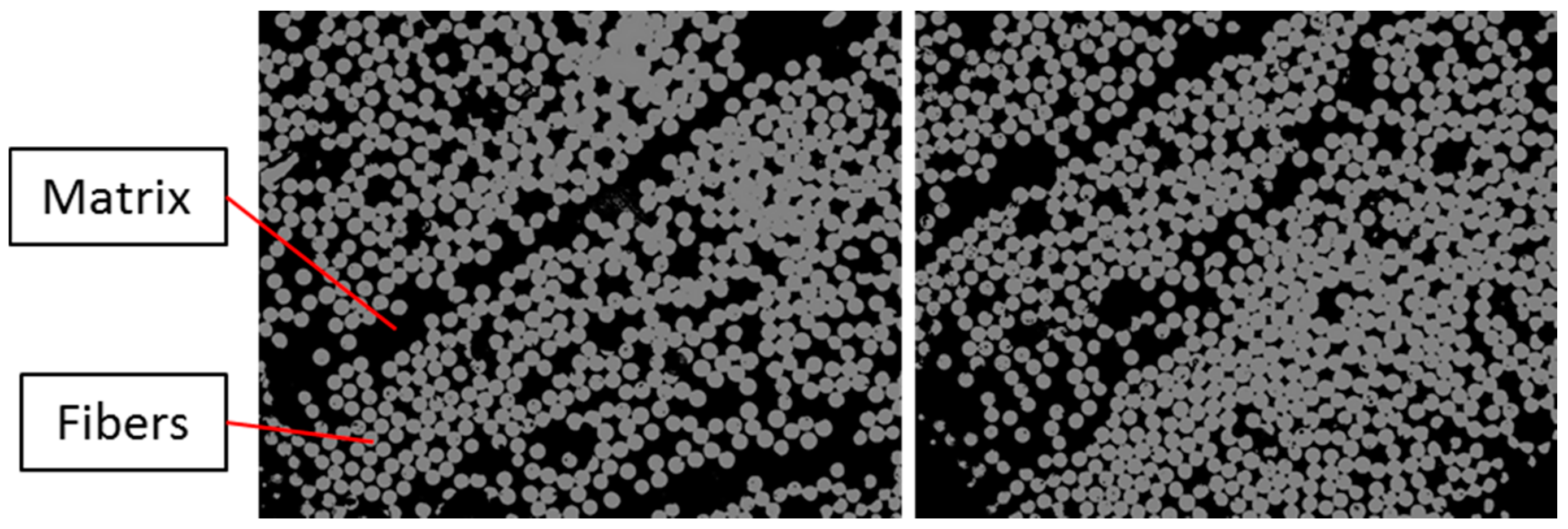
The fiber volume content of the manufactured CMC samples was determined through a grey scale analysis of five different sections of the material, as shown in Figure 8. An average value of 55% was obtained.
3.4. Flexural Strength
The experiment plan of the mechanical characterization was conceived to analyze the influence of the coatings on the fiber/matrix interface and the oxidation resistance of composites. In order to limit the complexity and experimental effort of the study, two material systems were investigated:
- Untreated HM carbon fiber-reinforced SiOC (reference)
- 3 wt. % SILRES® MK-coated HM carbon fiber-reinforced SiOC
The reason to select 3 wt. % SILRES® MK-coated fibers for this investigation is their weak oxidation resistance performance compared with the other types of coated fibers tested. Therefore, the results of the oxidation resistance of composites shown in the following paragraph are quite conservative.
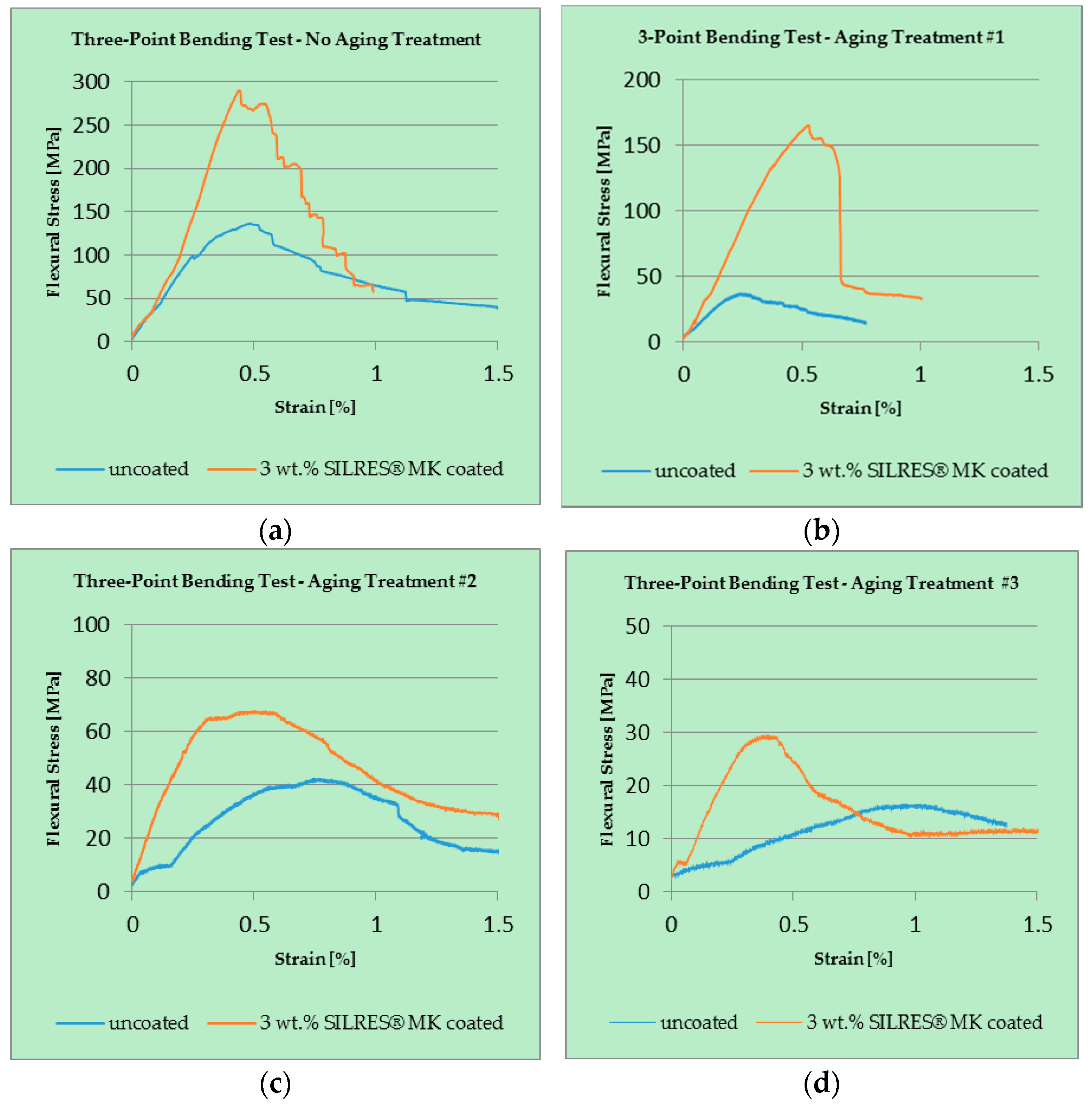
Figure 9 shows representative three-point bending stress–strain plots for composites exposed to different aging treatments.
The curves of Figure 9a, which were tested without any aging treatment, demonstrate the influence of the fiber treatment on the mechanical response of the composites. Although the flexural modulus is similar for both samples, there is a marked increase of flexural strength for the sample from coated fibers. This sample also exhibits an optimal pseudo-ductile mechanical response, which must be linked with an improved fiber–matrix adhesion introduced by the fiber coating.
Figure 9a–c presents the evolution of the mechanical properties of samples from coated and uncoated filaments after three different aging treatments. The first aging treatment, a 60-min exposure to an oxidative environment at 600 °C, is the most prominent case of positive influence of the SILRES® MK coating. Whereas when the strength of the unprotected fiber-reinforced SiOC remains below 50 MPa, the coated fiber-reinforced SiOC’s is above 150 MPa.
Although after aging treatments #2 and #3, samples from treated fibers exhibit a slightly better performance as reference samples, the differences are minor. Therefore, it can be concluded that the protecting effect of the fiber treatment is limited with respect to time and temperature, and is relevant only for treatment #1.
3.5. Fractographic Study
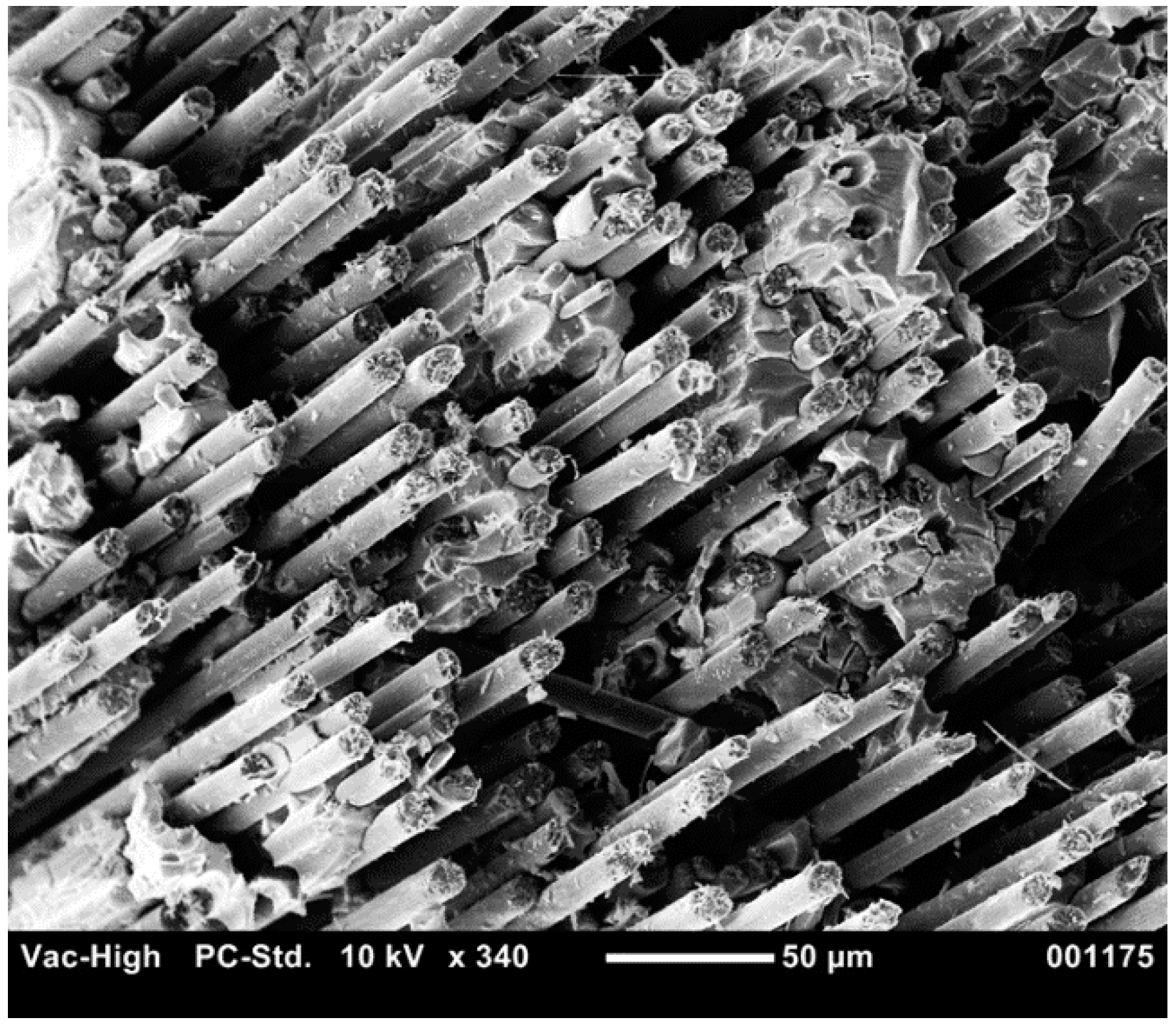
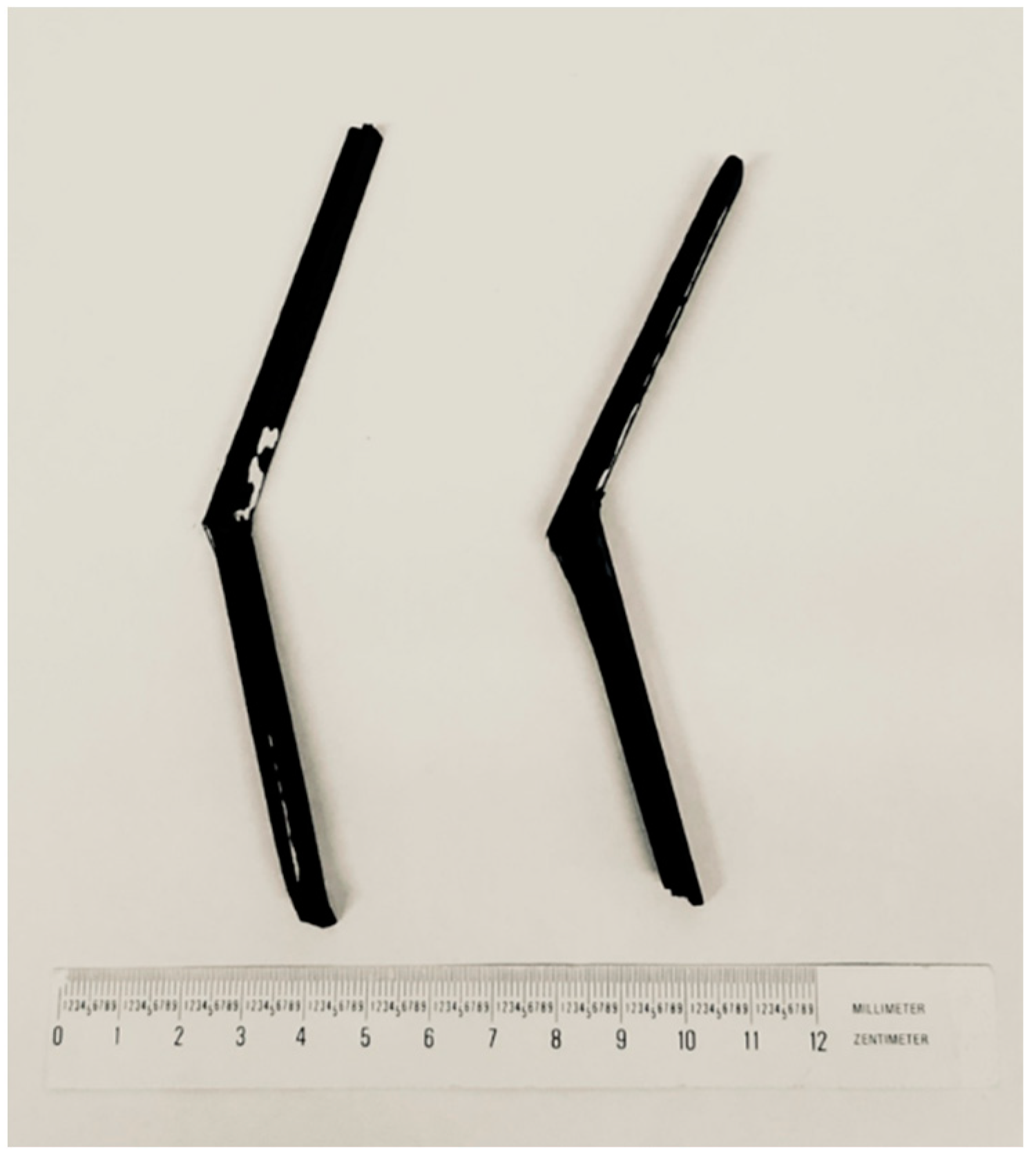
The fracture surfaces of the tested CMC samples were also analyzed. Figure 10 shows a typical fiber pull-out mechanism observed for a sample from 3 wt. % SILRES® MK-coated HM carbon fibers without any aging step under an SEM microscope. This effect was also observed for the CMC samples manufactured from reference fibers. Figure 11 shows this pseudo-ductile failure behavior on a macroscopic scale.
4. Discussion
The severe non-linear mass loss process of the reference high modulus carbon fibers contrasts with the linear oxidation kinetic observed for all of the coated fibers. This fact hints at an oxidation process in which a diffusion controlled step is involved. Most probably, this step is the inward diffusion of oxygen and the outward diffusion of oxidation products such as CO and CO2 through the thin presumably nanoporous [18] tubular silicon oxycarbide coating layer.
In relation to the signs of oxidation observed around the ends of the coated rovings, it must be underlined that the tested samples are chopped fibers from continuously coated rovings. Therefore, there is an open and unprotected circular surface at the end of each single filament, which can affect the oxidation resistance of whole bundle, accelerating its degradation. This effect would be minimized for samples with a higher aspect ratio.
5. Conclusions
The poor oxidation resistance of the high modulus carbon fibers was significantly improved by the deposition of thin ceramic layers on the filaments by continuous liquid phase coating (CLPC). The protecting effect of the fiber coatings in the manufactured CMC samples was proven to be relevant with respect to time and temperature to a treatment at 600 °C for 60 min in air. For the treatments at 600 °C for 120 min and at 650 °C for 30 min, this protecting effect is not relevant anymore.
In relation to the influence of the fiber coatings on the mechanical properties of the not-aged CMC samples, the three-point bending tests proved an increase of the flexural strength, maintaining the pseudo-ductile failure behavior.
Author Contributions
R.G. supervised the study; M.J. conceived and designed the experiments; A.S. performed the experiments and analyzed the data; F.K. reviewed the manuscript and J.B. provided thermal analysis equipment and scientific support.
Funding
This research received no external funding.
Conflicts of Interest
The authors declare no conflict of interest. The founding sponsors had no role in the design of the study; in the collection, analyses, or interpretation of data; in the writing of the manuscript, and in the decision to publish the results.
References
- Evans, A.G. Perspective on the Development of High-Toughness Ceramics. J. Am. Ceram. Soc. 1990, 73, 187–206. [Google Scholar] [CrossRef]
- Sauder, C. Ceramic Matrix Composites: Nuclear Applications. In Ceramic Matrix Composites: Materials, Modeling and Technology; Bansal, N.P., Lamon, J., Eds.; Wiley: Hoboken, NJ, USA, 2015; pp. 609–646. [Google Scholar]
- Mouritz, A.P. Introduction to Aerospace Materials; Elsevier: New York City, NY, USA, 2012. [Google Scholar]
- Chawla, K.K. Composite Materials: Science and Engineering; Springer Science & Business Media: Berlin, Germany, 2012. [Google Scholar]
- Singh, J.P.; Singh, D.; Sutaria, M. Ceramic composites: Roles of fiber and interface. Compos. Part A Appl. Sci. Manuf. 1999, 30, 445–450. [Google Scholar] [CrossRef]
- Tong, D.; Wang, H.; Wang, L.; Chen, L.; Li, Z. Coating of poly(carborane-carbosilane-phenylacetylene) on carbon fibers with excellent oxidation protection. Surf. Coat. Technol. 2017, 319, 335–344. [Google Scholar] [CrossRef]
- Latzel, S.; Vaßen, R.; Stöver, D. New Environmental Barrier Coating System on Carbon-Fiber Reinforced Silicon Carbide Composites. J. Therm. Spray Technol. 2005, 14, 268–272. [Google Scholar] [CrossRef]
- Westwood, M.E.; Webster, J.D.; Day, R.J.; Hayes, F.H.; Taylor, R. Oxidation protection for carbon fibre composites. J. Mater. Sci. 1996, 31, 1389–1397. [Google Scholar] [CrossRef]
- Koch, D.; Tushtev, K.; Grathwohl, G. Ceramic fiber composites: Experimental analysis and modeling of mechanical properties. Compos. Sci. Technol. 2008, 68, 1165–1172. [Google Scholar] [CrossRef]
- Thouiess, M.D.; Sbaizero, O.; Sigl, L.S.; Evans, A.G. Effect of Interface Mechanical Properties on Pullout in a SiC-Fiber-Reinforced Lithium Aluminum Silicate Glass-Ceramic. J. Am. Ceram. Soc. 1989, 72, 525–532. [Google Scholar] [CrossRef]
- Aggour, L.; Fitzer, E.; Heym, M.; Ignatowitz, E. Thin coatings on carbon fibers as diffusion barriers and wetting agents in Al composites. Thin Solid Films 1977, 40, 97–105. [Google Scholar] [CrossRef]
- Schmidt, S. Beschichtung von Kohlenstofffasern Durch Chemische Gasphasenabscheidung (CVD). Ph.D. Thesis, Technische Fakultaet—Universitaet Erlangen-Nuerenberg, Erlangen, Germany, 2004. [Google Scholar]
- Kern, F.; Gadow, R. Liquid phase coating process for protective ceramic layers on carbon fibers. Surf. Coat. Technol. 2002, 151–152, 418–423. [Google Scholar] [CrossRef]
- Gadow, R.; Kern, F. Continuous Liquid Phase Coating of Carbon Fibers with Kion VL 20® Polysilazane. Adv. Eng. Mater. 2003, 5, 799–801. [Google Scholar] [CrossRef]
- Riedel, R.; Gadow, R.; Klingebiel, U. Synthesis and High Temperature Stability of Amorphous Ceramics in the System Si-B-C-N Derived from Polymer Precursors and Their Application for Liquid Phase Coatingof Carbon Fibers: Sub-Project IFKB—Universität Stuttgart (Project Nr.: GA589/2-4); Project Report in the Framework of the DFG Priority Program; Unpublished work; 2018. [Google Scholar]
- Colombo, P.; Mera, G.; Riedel, R.; Sorarù, G.D. Polymer-Derived Ceramics: 40 Years of Research and Innovation in Advanced Ceramics. J. Am. Ceram. Soc. 2010, 73, 1805–1837. [Google Scholar] [CrossRef]
- Kern, F.; Gadow, R. Deposition of ceramic layers on carbon fibers by continuous liquid phase coating. Surf. Coat. Technol. 2004, 180–181, 533–537. [Google Scholar] [CrossRef]
- Deutsches Institut für Normung. Advanced Technical Ceramics—Mechanical Properties of Ceramic Composites at Room Temperature. Part 3: Determination of Flexural Strength; EN 658-3:2002; Deutsches Institut für Normung: Berlin, Germany, 2002. [Google Scholar]
Figure 1.
Schematic illustration of the continuous liquid P03B5hase coating (CLPC) plant.

Figure 2.
SEM images of different coated fibers: (a) 3 wt. % SILRES® MK-coated fibers; (b) 5 wt. % SILRES® H44 coated fibers; (c) 5 wt. % SILRES® H62 C coated fibers.
Figure 2.
SEM images of different coated fibers: (a) 3 wt. % SILRES® MK-coated fibers; (b) 5 wt. % SILRES® H44 coated fibers; (c) 5 wt. % SILRES® H62 C coated fibers.
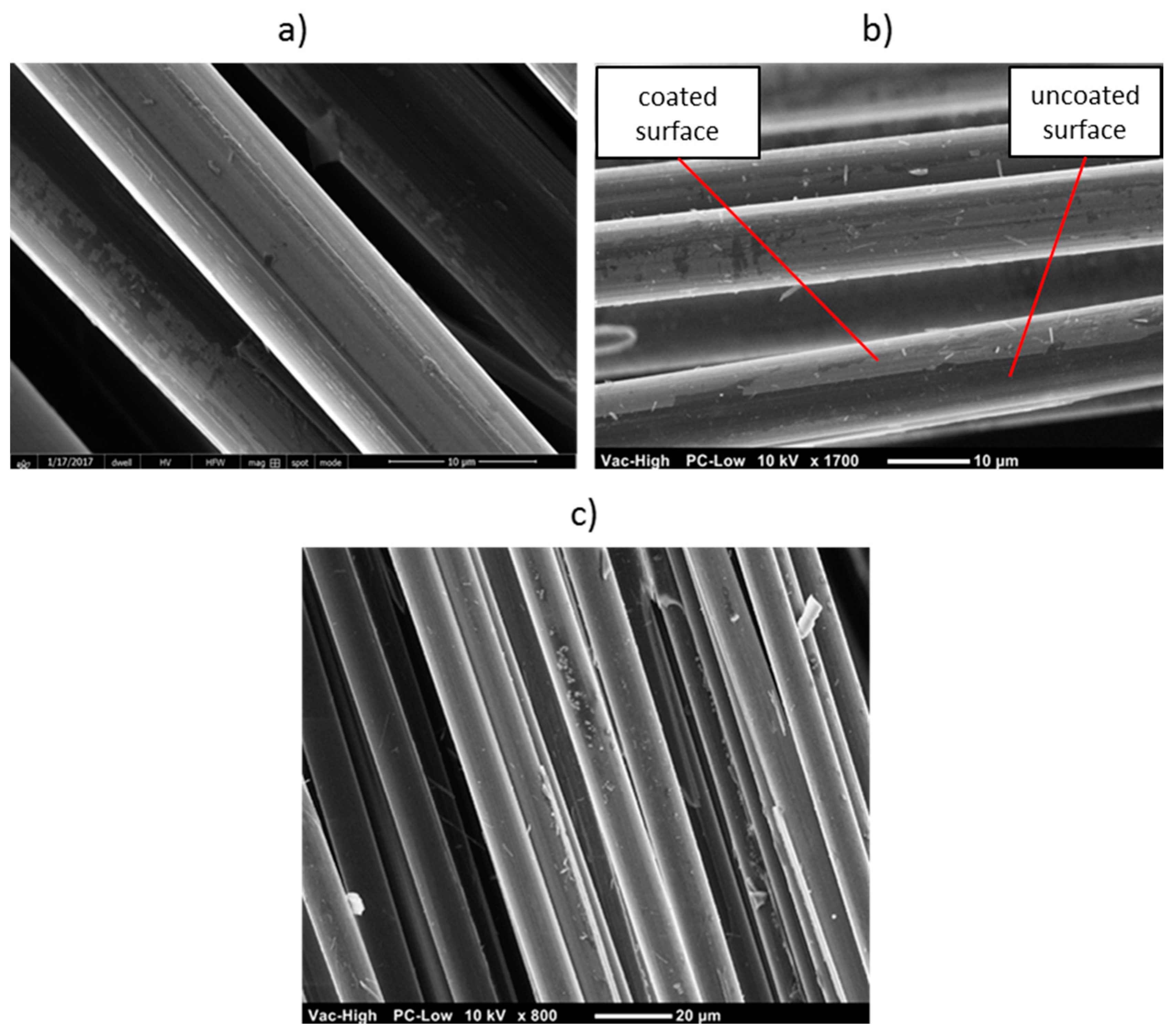
Figure 3.
Final mass reduction of untreated and coated carbon fibers according to the DTA-TG results.
Figure 3.
Final mass reduction of untreated and coated carbon fibers according to the DTA-TG results.

Figure 4.
DTA-TG diagram of the reference high modulus carbon fiber. Testing conditions: heating rate 20 K/min; O2 atmosphere; flow rate 160 mL/min.
Figure 4.
DTA-TG diagram of the reference high modulus carbon fiber. Testing conditions: heating rate 20 K/min; O2 atmosphere; flow rate 160 mL/min.
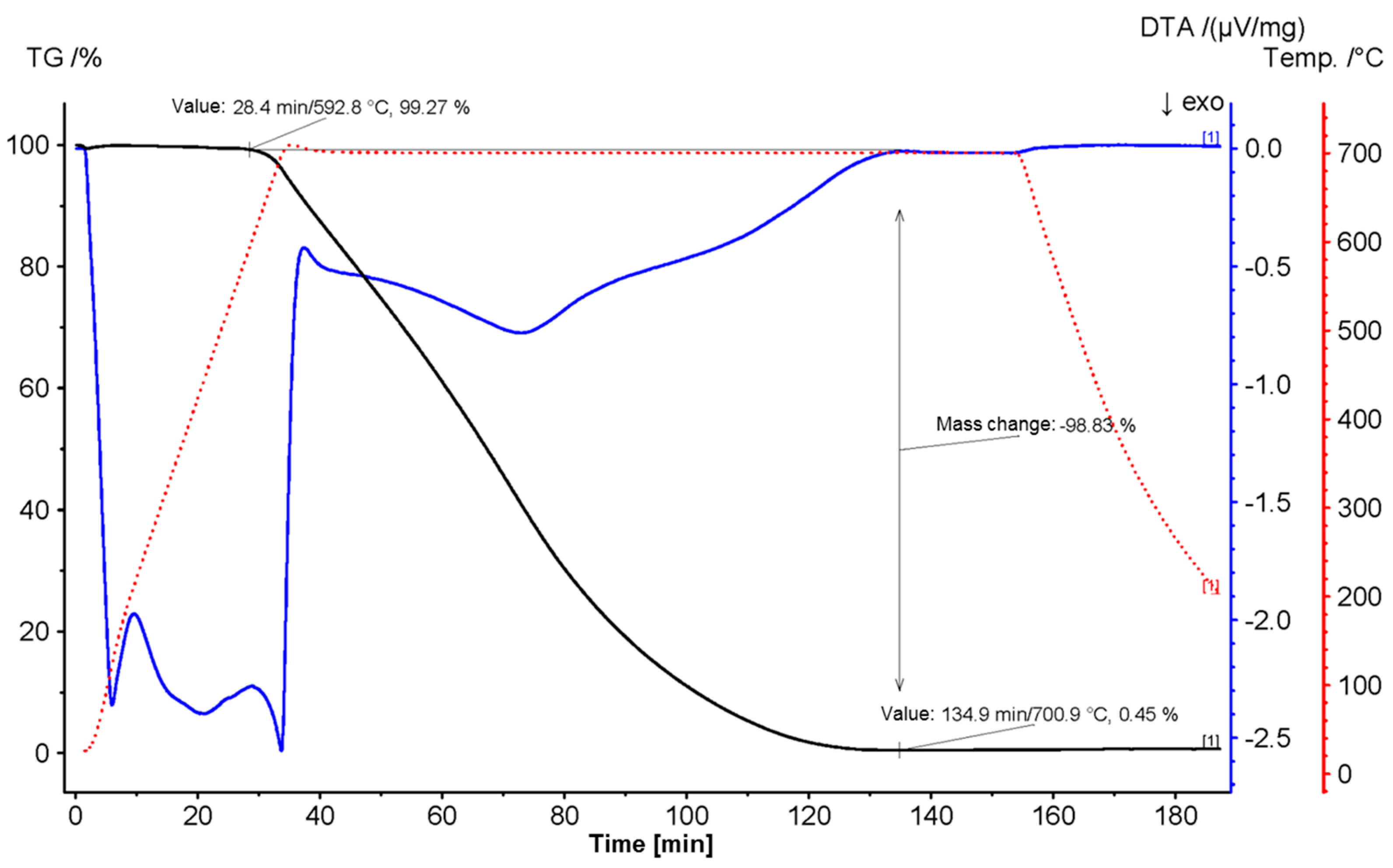
Figure 5.
DTA-TG diagram of 3 wt. % SILRES® MK-coated HM carbon fiber. Testing conditions: heating rate 20 K/min; O2 atmosphere; flow rate 160 mL/min.
Figure 5.
DTA-TG diagram of 3 wt. % SILRES® MK-coated HM carbon fiber. Testing conditions: heating rate 20 K/min; O2 atmosphere; flow rate 160 mL/min.
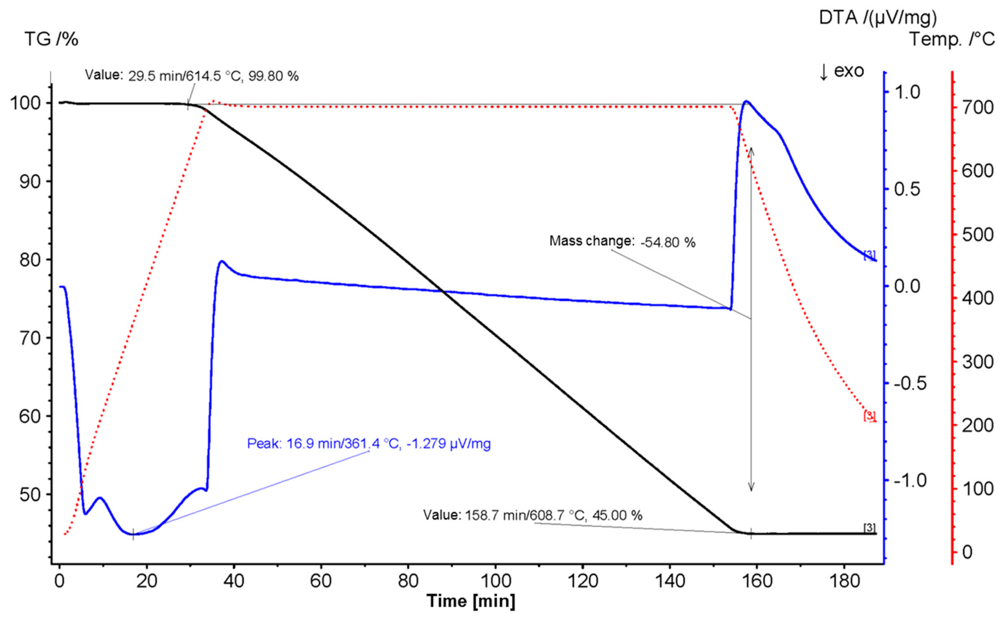
Figure 6.
DTA-TG diagram of 5 wt. % SILRES® H62 C-coated HM carbon fiber. Testing conditions: heating rate 20 K/min; O2 atmosphere; flow rate 160 mL/min.
Figure 6.
DTA-TG diagram of 5 wt. % SILRES® H62 C-coated HM carbon fiber. Testing conditions: heating rate 20 K/min; O2 atmosphere; flow rate 160 mL/min.
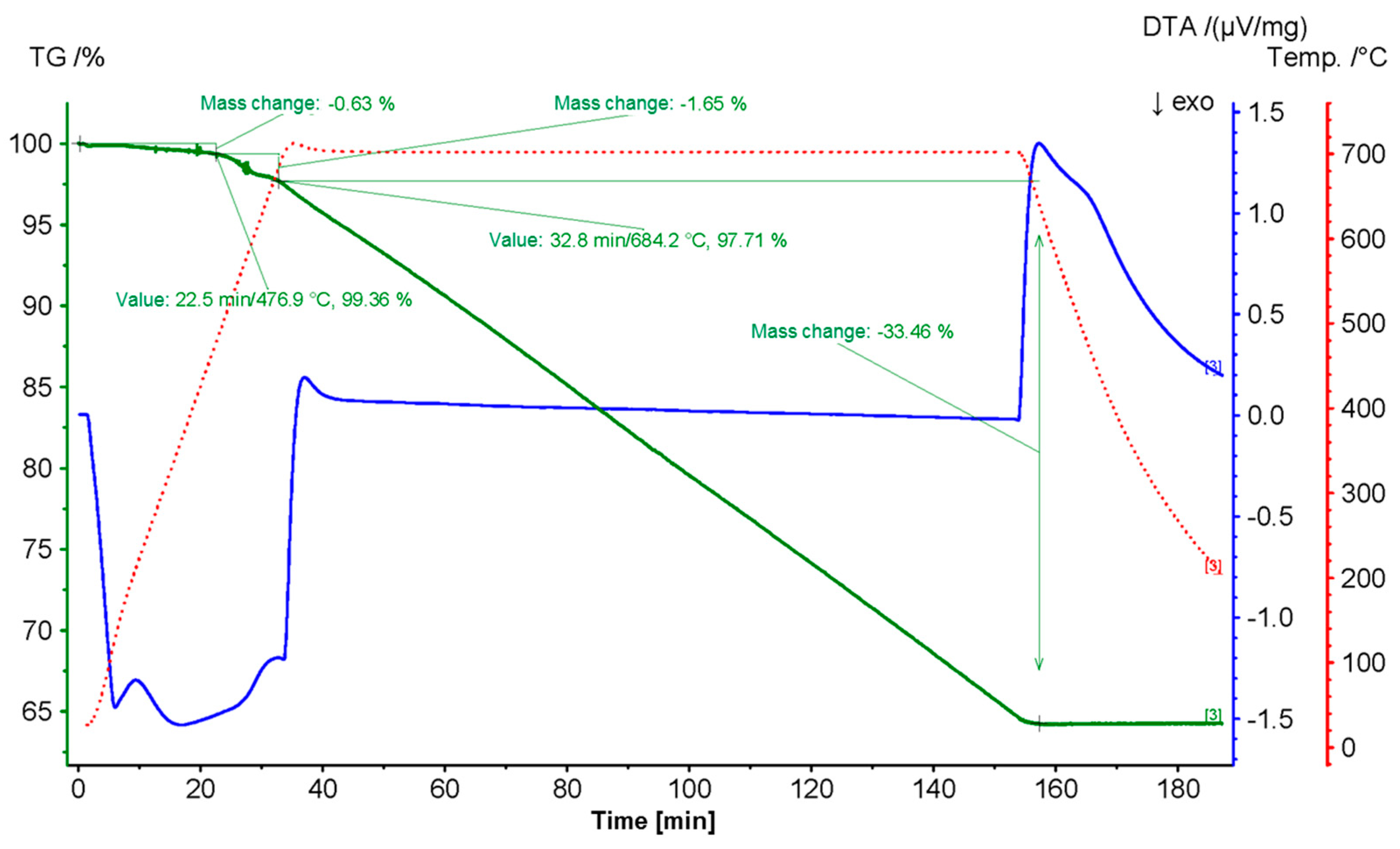
Figure 7.
SEM images of differently treated HM carbon fibers after DTA-TG test: (a) untreated; (b–d) coated with 5 wt. % SILRES® H62 C solution.
Figure 7.
SEM images of differently treated HM carbon fibers after DTA-TG test: (a) untreated; (b–d) coated with 5 wt. % SILRES® H62 C solution.
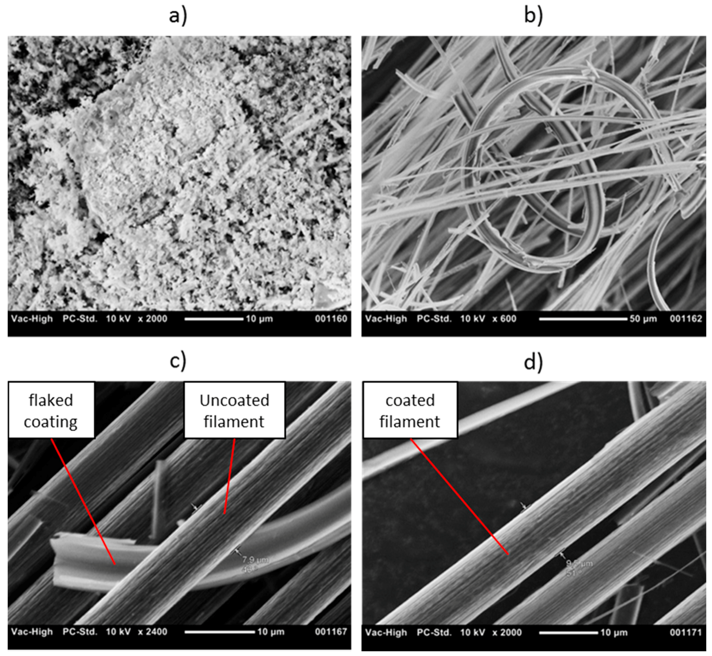
Figure 8.
Measurements of fiber volume content in two different microsections via grey scale.

Figure 9.
Most representative three-point bending stress–strain curves for SiOC ceramics reinforced by unmodified and 3 wt. % SILRES® MK-coated HM carbon fibers: (a) before any aging treatment; (b) after aging treatment #1600 °C for 60 min; (c) after aging treatment #2650 °C for 30 min; (d) after aging treatment #3600 °C for 120 min.

Figure 10.
Fracture surface of ceramic matrix composites (CMC) sample manufactured with 3 wt. % SILRES® MK-coated HM carbon fibers.
Figure 10.
Fracture surface of ceramic matrix composites (CMC) sample manufactured with 3 wt. % SILRES® MK-coated HM carbon fibers.

Figure 11.
Tested CMC samples from: (left) untreated HM carbon fibers and (right) 3 wt. % SILRES® MK coated HM carbon fibers.
Figure 11.
Tested CMC samples from: (left) untreated HM carbon fibers and (right) 3 wt. % SILRES® MK coated HM carbon fibers.


Table 1.
Coating solutions employed for the coating process.
| Precursor | Precursor Type | Concentration | Solvent |
|---|---|---|---|
| Silikoftal® HTT (Evonik, Essen, Germany) | Silicon Polyester Resin | 10% | MEK |
| KDT HTA 1500 (KiON Defense, Huntingdon Valley, PA, USA) | Polysiloxazane | 5% | MEK |
| SILRES® H 44 (Wacker, München, Germany) | Phenylmethyl Polysiloxane Resin | 5% | MEK |
| SILRES® H62 C (Wacker) | Polysiloxane | 5% | MEK |
| SILRES® MSE 100 (Wacker) | Methyl Polysiloxane | 10% | MEK |
| SILRES® MK (Wacker) | Methyl Silicon Resin | 3% | Isopropanol |
Table 2.
Temperature and duration of the thermal aging treatments.
| Aging Treatment | Temperature (°C) | Duration (min) |
|---|---|---|
| #1 | 600 | 60 |
| #2 | 650 | 30 |
| #3 | 600 | 120 |
© 2018 by the authors. Licensee MDPI, Basel, Switzerland. This article is an open access article distributed under the terms and conditions of the Creative Commons Attribution (CC BY) license (http://creativecommons.org/licenses/by/4.0/).
Share and Cite
MDPI and ACS Style
Jiménez, M.; Samie, A.; Gadow, R.; Kern, F.; Bill, J. Siloxane Precursor-Based Protective Coatings for High Modulus Carbon Fibers in Ceramic Matrix Composites. Ceramics 2018, 1, 128-138. https://doi.org/10.3390/ceramics1010011
AMA Style
Jiménez M, Samie A, Gadow R, Kern F, Bill J. Siloxane Precursor-Based Protective Coatings for High Modulus Carbon Fibers in Ceramic Matrix Composites. Ceramics. 2018; 1(1):128-138. https://doi.org/10.3390/ceramics1010011
Chicago/Turabian StyleJiménez, Miguel, Armaghan Samie, Rainer Gadow, Frank Kern, and Joachim Bill. 2018. "Siloxane Precursor-Based Protective Coatings for High Modulus Carbon Fibers in Ceramic Matrix Composites" Ceramics 1, no. 1: 128-138. https://doi.org/10.3390/ceramics1010011