Fatigue-Damage Evolution of Notched Composite Multilayered Structures under Tensile Loads


Institute of Machine Design, Cracow University of Technology, 31-864 Kraków, Poland
*
Author to whom correspondence should be addressed.
J. Compos. Sci. 2018, 2(2), 27; https://doi.org/10.3390/jcs2020027
Submission received: 12 March 2018
/
Revised: 3 April 2018
/
Accepted: 16 April 2018
/
Published: 18 April 2018
Abstract
:The problems discussed in the present paper are well-known both from the theoretical (numerical) and experimental point of view. The novelty of our approach depends on the application of hybrid experimental methods and a comparison of their effectiveness in the description of complicated fatigue problems arising in the analysis of the behavior of laminated panels with open holes and subjected to tensile loading. Three experimental methods were used: infrared thermography (passive), structural health monitoring (active), and digital image correlation. The experimental investigations were supplemented by the finite element description of the problem dealing mainly with the static behavior, monitoring the development and final fracture of composites. The considerations concern laminated panels oriented at ±45° with different types of holes, i.e., vertical elliptical, horizontal elliptical, and circular.
1. Introduction
A typical problem designers have to face during the development of a new product made of composite materials is the presence of joints, notches and openings. The behavior of such structures either in isotropic or composite materials has been extensively investigated in the last few decades analytically, numerically and experimentally. However, the problem of static and fatigue design of notched composite laminates is still far from being resolved due to the significant influence of several design parameters on behavior and final failure. During static or fatigue loading of a notched laminate, high stresses exist near the notch root and result in much more rapid degradation of the material in the vicinity of the notch than throughout the rest of the laminated structure. The first investigations [1,2] were carried out in the area of aircraft/aerospace applications and dealt mainly with the analysis of laminated panels with circular notches, oriented at [0°] or [0°/±45°] and subjected to tensile loading. Those studies demonstrated the complex form of the static and fatigue-failure initiation, the growth, and the final damage that consisted of the mixture of splitting along the fiber directions and delaminations between layers. It was observed that matrix-dominant failure was common in the early stages of in-plane loading and initiates around the open hole. The primary mode of fatigue failure of notched unidirectional angle-ply laminates was the propagation of cracks parallel to one of the fiber directions. In the case of woven-roving structures with fibers in directions of applied tensile stress, the cracks propagate transversely across the specimen. A broader review of published papers in this area is presented e.g., by Shokrieh [3,4] and Muc, Romanowicz [5]. The fatigue failure and damage analysis of composites with an open hole is also discussed by Khan et al. [6,7]. These papers make also clear distinctions between the empirical and continuum damage mechanics-based models for fatigue analysis.
The fatigue life predictions and the response of multilayered composite structures under cyclic loading can be investigated with the use of different fatigue models. The commonly used approach can be classified into the following categories [8,9]: strength and stiffness degradation models, stochastic and probabilistic models, fatigue-life models, and continuum-damage models based [10] and micromechanics models.
The development of the experimental techniques allows us to monitor the particular phases of the static and fatigue damage growth around the holes. Sims [11], Kuhn et al. [12] discussed in detail various methods that can be applied in the analysis of the aforementioned problems. The authors divided the existing NDT (non-destructive testing) methods into five groups relating to the physical method applied in the analysis: (a) mechanical (ultrasonic or acoustic emission); (b) thermal (thermography—passive or active); (c) magnetic (eddy current); (d) X-ray (tomography); and (e) visual (penetrant testing or CCD (charge-coupled device) camera). They introduced also six criteria characterizing the suitability of the particular NDT techniques in the examination/evaluation of an individual problem. It is worth emphasizing that in the present literature it can be observed that the use of hybrid methods is preferred; see for example Kordatos et al. [13], Zalamaeda et al. [14].
Since the growth of the literature in the area of the NDT methods applied to the analysis of fatigue problems in notched laminated structures is drastically increasing, we limit our review to monographs and fundamental works devoted to the problems considered in the present paper. Our attention is mainly focused on the hybrid application of three methods: passive infra-red thermography, active structural health monitoring (SHM) using piezoelectric (PZT) transducers, and the digital image correlation (DIC) method.
The application of infrared termography to monitoring damage in materials and mechanical structures is described in detail by Maldague [15], Vavilov [16] and Meola et al. [17]. The latter monograph is devoted in particular to the analysis of composite structures. The review of existing work in this area is also shown in the work Muc, et al. [18].
The general description of the SHM methods is given by Giurgiutiu [19]. The author introduced also the classification of SHM methods. The characterization of the specific problems arising in the analysis of composite plates and shallow panels is demonstrated, for example, by Muc, Stawiarski [20].
The digital image correlation (DIC) method allows us to obtain accurate displacement and surface-strain distributions (called the speckle pattern) of the analyzed isotropic or composite structures under static or cyclic loads. It is an optical technique that measures deformation by comparing images from an unloaded reference surface to a deformed surface. For 2D measurements, only one camera is enough, but to evaluate 3D-displacement fields, two cameras are required in image acquisition. The broader discussion of this method as well as the existing variants of numerical packages suitable for the analysis is presented by Sutton et al. [21]. The possibility of applications depends entirely on the particular problem considered by researchers.
The aim of the present paper is twofold:
- to demonstrate the failure forms of the plates and cylindrical panels and to confront them with finite element (FE) analysis;
- to compare the experimental results for the hybrid analysis including the infra-red thermography, the SHM and the DIC methods, and to evaluate the effectiveness of these methods for static and fatigue tests.
The analysis is conducted for laminated plates and cylindrical shallow shells with elliptical (horizontal and vertical) and circular central holes. The composite panels are made of woven roving fabrics and unidirectional laminates oriented at ±45°.
2. Experimental Equipment
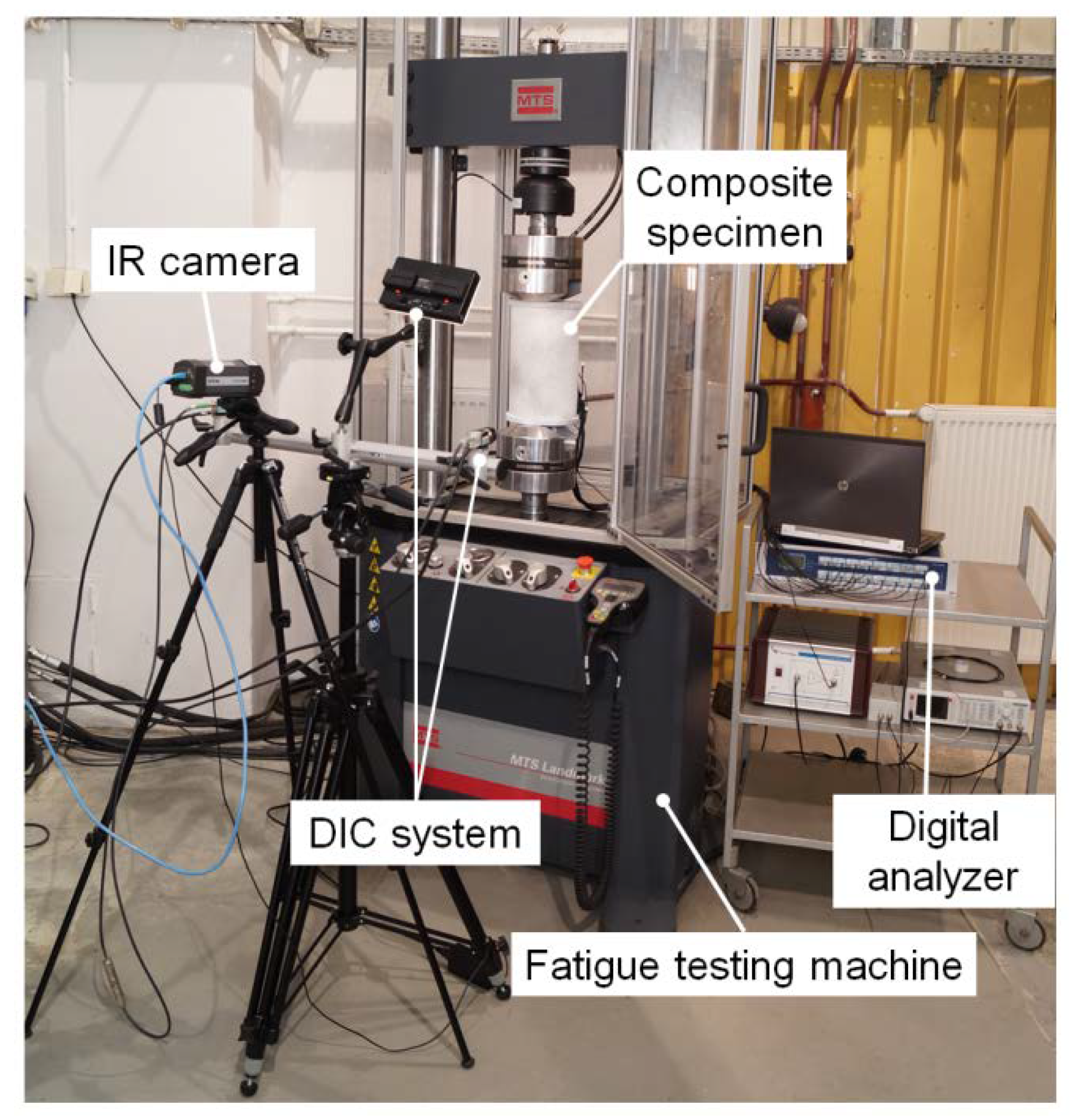
The experimental fatigue tests were performed on the MTS Landmark 370 servo hydraulic testing machine. Samples tabbed at both ends, installed in grips designed for fatigue tests, were mounted in the MTS 647.10A (max. loading—100 kN) hydraulic wedge grips. The experimental fatigue tests were made under force control mode; however, different maximum stress levels were applied depending on the geometry and material of specimens. The experimental tests were conducted with the use of: (1) the infrared (IR) passive thermography system; (2) the active structural health monitoring system; and (3) the digital image controller system—Figure 1.
The acquisition of the thermal field was made with the use of a thermography Flir A325 IR camera (FLIR Systems, Inc., Wilsonville, OR, USA) Damage detection and control were also made using the active SHM system for the wave-propagation analysis. For the active pitch-catch measurement technique, the Noliac CMAP06 (Noliac, Kvistgård, Denmark) piezoelectric transducers with dimension 3 × 3 mm2 and 2 mm height are used. One of them is used as an actuator which excites the five cycles of the Hanning windowed tone burst excitation signal with 100 kHz frequency. The full-field displacement and strain analysis were conducted using the 3D-digital image correlation stereo system DANTEC Q-400 (Dantec Dynamics, Skovlunde, Denmark).
3. Mechanisms of Failure Modes for Multilayered Panels with Open Holes
For unidirectional rectangular coupons (without holes) subjected to tensile loads, a ply has different deformations with respect to the direction of loading (Figure 3):
- In the fiber direction, the behavior is almost elastic. The damage is observed before the final fracture. Three major intralaminar mechanisms are responsible for all observed non-linearities in the stress–strain curve of a composite lamina: matrix microdamage, matrix macroscopic cracking (modes I and II), and axial fiber failure (mode I).
- In shearing, obtained from a tension test on a ±45° laminate, we can observe a non-linear behavior; there are anelastic strains. We can observe a classical behavior in the form of splitting along the fiber direction (the intralaminar mechanisms) associated with delaminations (the interlaminar mechanism).
The material used in the tension static and fatigue experiments was a unidirectional glass/epoxy composite and a glass woven-roving fabric/epoxy resin. Their mechanical properties are presented in Table 2.
Figure 4 demonstrates the static deformations of the open hole panels having the following stacking sequence [+45°/−45°]4. At the beginning of the loading process the random scatter of splits along fiber directions was observed. Then, the splits accumulated along four major directions and formed the “X” pattern. All cracks were initiated and then emanated at the tangent directions of holes—see Muc, Romanowicz [5]. As can be observed for the increasing load delaminations appeared along the x-axis, their influence was much more significant for horizontal ellipses. The static damage patterns [(0°/90°)4]S and [(0°/45°/90°/−45°)2]S for glass epoxy laminate with an open hole were also investigated by Khan [22]. The reference [22] shows a detailed failure plot around the hole based on five different modes of failure on a ply-by-ply basis. Tohgo et al. [23] proposed use of the mixed-mode condition for the description of the splitting crack initiation (tension and shearing). Bazhenov [24] applied the single-mode criterion (the second mode of fracture) but for the splits propagated along fibers oriented at 0° (panels with circular holes).
For cylindrical panels (the stacking sequence [+45°/−45°]4) with circular holes the fracture pattern “X” (Figure 5a) is identical to those plotted in Figure 4. However, for plates made of woven-roving fabrics the standard first mode of fracture occurred (Figure 5b). More information about the fracture analysis and results can be found in Ref. [5].
Even for static loading, it is very difficult to conduct detailed accurate progressive failure analysis of deformations since splits have a stochastic character [22]. Hu et al. [25] presented such results obtained with the use of an approximated stress–strain diagram, however, the authors did not take into account delaminations arising during deformations. Achard et al. [26] introduced the special FE model (the interface finite elements in the form of 3D springs) allowing investigation of the development of delaminations and splits, but they assumed the deterministic character of splitting cracks.
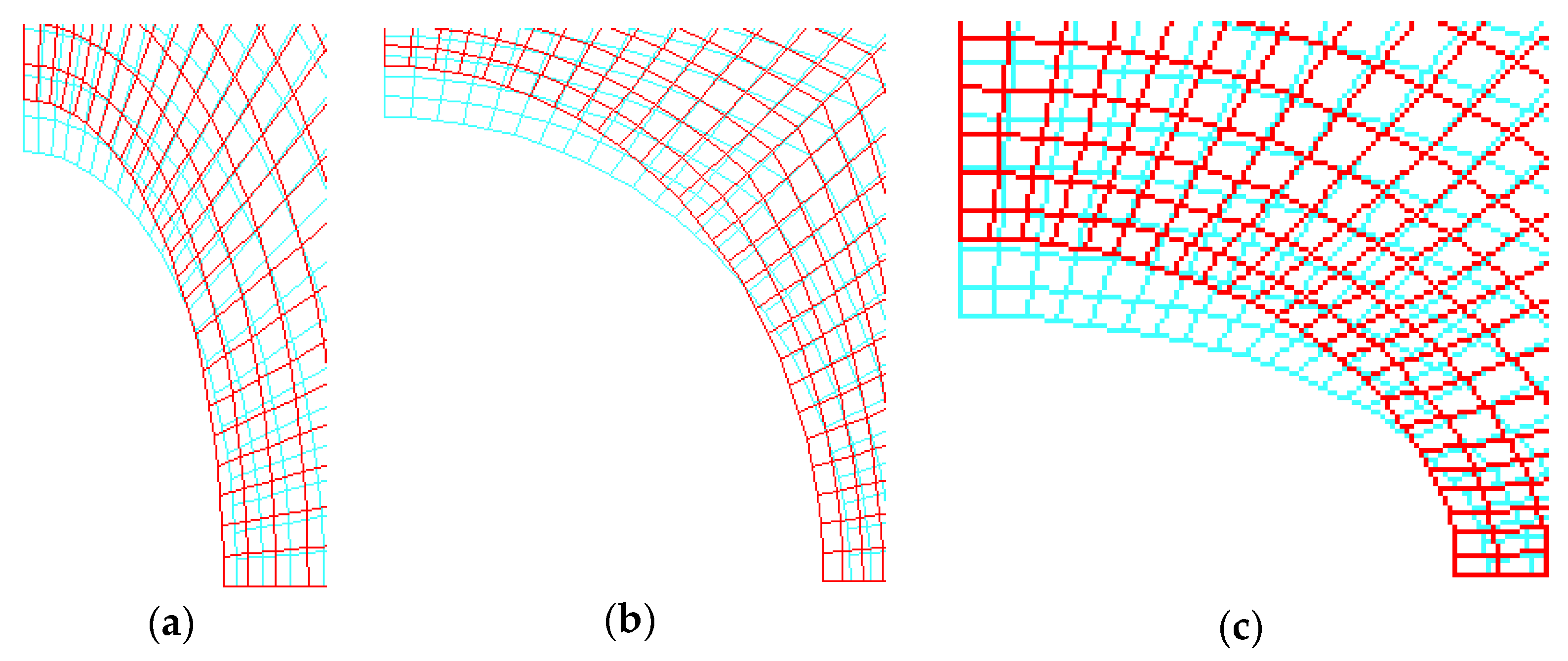
Composite panels with open holes subjected to uni-axial tension along the y-direction exhibited one very characteristic feature, i.e., global/local buckling under tension due to the combined effects of tension and compression arising around the hole—Figure 6. Kremer and Schurmann [27] indicated that the initiation of buckling could precede fracture due to stress concentrations and result in final failure (modes and loads) both under static and fatigue-loading conditions.
It is worth emphasizing that the analysis in this section deals mainly with the static behavior of panels with cutouts; however, the problems discussed above (i.e., failure modes and their description) may be simply transferred to the fatigue analysis.
4. Fatigue Analysis—Experimental Results
Composite panels with circular and elliptical holes were tested to ultimate failure in a fatigue with the mean tensile load equal to 80% of the static failure load (see Figure 4). The maximal and minimal stresses were equal to ±10% of the mean load values.
4.1. Infra-Red Thermography (Passive)
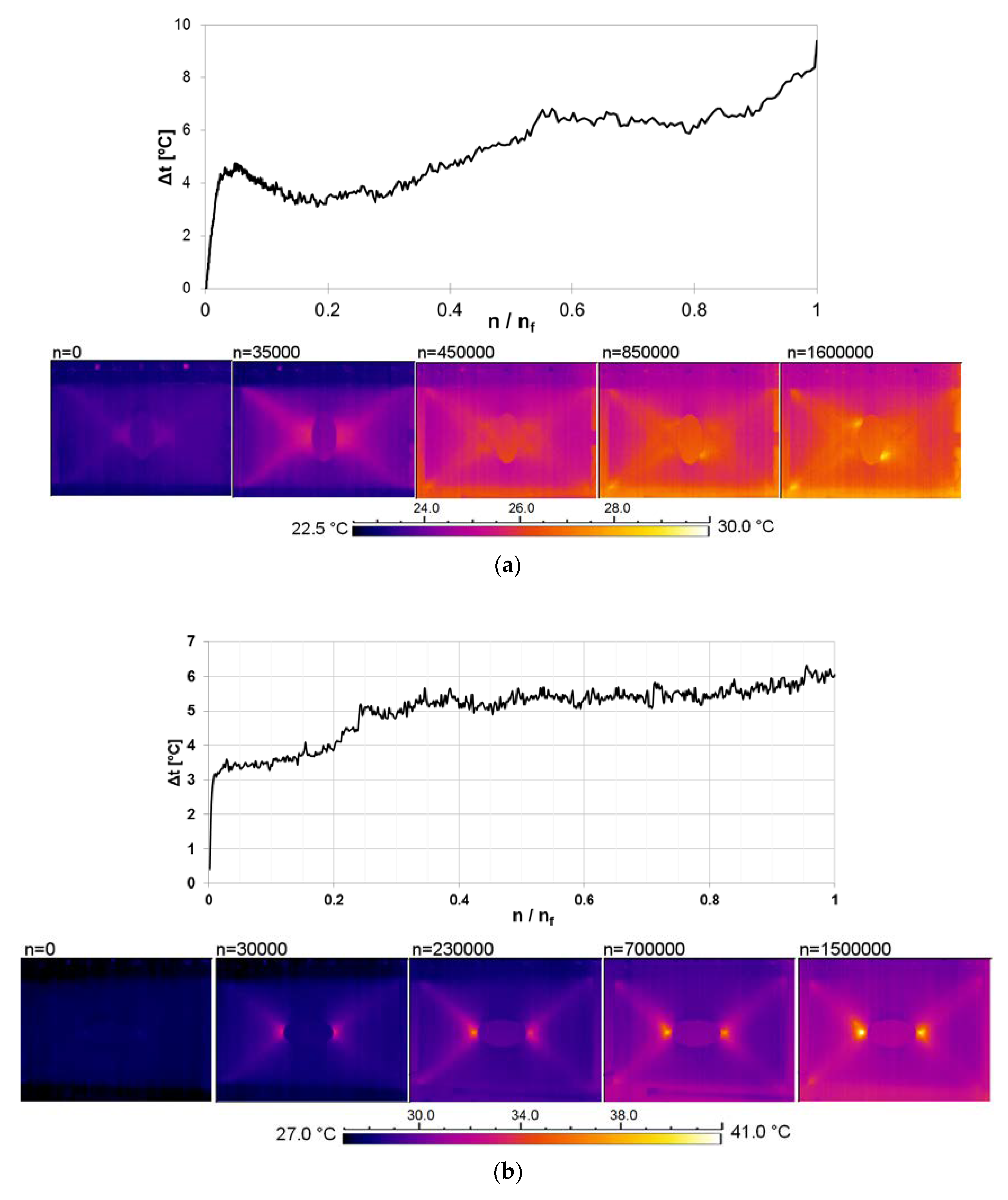
In the thermography analysis both passive and active methods are used. As it is claimed in the literature [28,29,30] the active infrared thermography (IRT) enables a full field visualization of surface-stress distribution. However, the use of thermoelastic stress analysis (TSA) is needed in such circumstances. As will be demonstrated, the application of the passive method is sufficient to detect fatigue evolution and final damage. For a different number of loading cycles and shapes of holes, thermal images are presented in Figure 7. Around half of hole circumferences (at the edges of circles or ellipses y = 0), the localized rise in temperature gradient Δt (as a function of number of cycles—n related to the total number of cycles nf) is used as a method of monitoring fatigue-damage growth.
At the beginning, the maximum surface temperature over the structures is almost constant up to 5000 cycles. Then, the temperature starts to increase in the middle of the holes for horizontal ellipses and circular holes. For the vertical elliptical holes, the distributions of temperature become unsymmetrical. The rate of the temperature growth is the highest for the vertical ellipse and the lowest for the horizontal ellipse. The locations of the maxima of the temperature rise vary along the circumferences, since the positions of the damage initiations and further damage growth depend on the hole geometry—see Muc, Romanowicz [5]. Distributions of temperatures around the holes is non-homogeneous since local matrix cracks (splits) arise at the fiber directions 45° and −45° simultaneously, and thermal images demonstrate the global picture on the 2D plate surface only. When the increase of the temperature rise is significant, the complex damage pattern appears in the form of matrix cracks and delaminations. The maximal temperature rise of 37 °C is far below the glass-transition temperature of the matrix.
4.2. Structural Health Monitoring (SHM) Method (Active)
Modeling wave propagation is usually associated with the modeling techniques for piezoelectric-laminated composite-coupled construction where the piezoelectrics are used to generate (actuators) and collect (sensors) elastic waves. Piezoelectric layers can be embedded inside multilayered composite structures or piezoelectric disks can be mounted on the top or bottom surfaces. Generally, guided waves in panel-laminated structures can manifest themselves as longitudinal, transverse (shear), Rayleigh (surface), Lamb (plate), Stoneley and creep modes, according to the particle motion style induced—see e.g., Bindal [31].
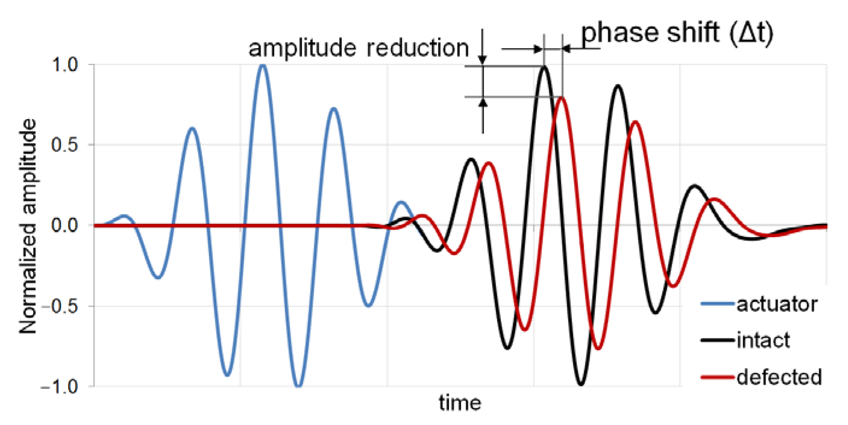
The classical Lamb wave propagation properties, such as amplitude, phase shift, and velocity, are strictly connected with the locations of actuators and sensors, geometrical dimensions of the tested object, and test frequency. A 3.5-cycle tone-burst signal, applied to the top surface of the piezoelectric actuator, is used in this study as an excitation signal—Figure 8.
The change of the Lamb-wave response measured by the PZT sensor is characterized by the phase shift Δφ, the normalized amplitude reduction ΔA and the time of flight ToF (Figure 8). The response signal data demonstrate the influence of defects, but usually the received signal contains the scattered waves from all cracks (splits), delaminations as well as from the boundaries of the plate including the hole edge. The results are also affected by the frequency of the signal generated by the actuator. It is much better to correlate the response with the FE predictions. However, such a procedure is impossible for fatigue tests due to the random character of splits and delaminations arising during the progressive failure of structures. In our opinion, the random character and the total number of the cracks (splits) occurring in the panels during fatigue damage does not allow the crack length, direction and growth to be quantified during the fatigue analysis. It is necessary to introduce the parameters and forms of the uncertainties characterizing the problem of the fatigue analysis of composite structures with holes. Figure 9 demonstrates evidently that the signals received at the final stage of fatigue damage growth are completely damped (degenerated) by the variety of signals from various sources of individual damage (local splits and delaminations) and by the waves reflected from the plate boundaries.
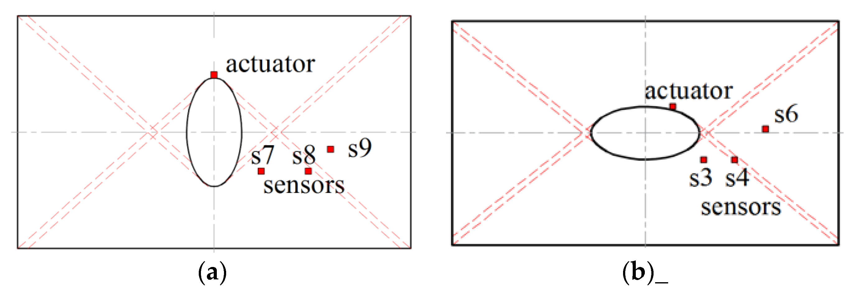
To demonstrate and compare the ultrasonic transmission of the Lamb waves for different types of elliptical holes, an active sensor network was arranged in the form of three similar paths (see Figure 10): I—actuator and sensors s3 or s7 where the wave crossed the hole, II—actuator and sensors s8 or s4 where the wave moved at the direction of the cracks along the fibers oriented at 45° (red lines in Figure 10) and III—actuator and sensors s9 and s8 where the wave was transmitted mainly in the composite plate area. Note that the proposed paths resembled the “X” pattern of splits—see Figure 4.
In general, with the increasing number of cycles and, in this way, the propagation of cracks, the amplitudes of the response waves always decrease, whereas the phase change increases—Figure 11. However, those results cannot be used for the quantitative evaluation of the fatigue degradation. For the simplest example of a single crack in an aluminum specimen, the discrepancy between theoretical predictions and variations of the signal-processing features was also observed [32].
4.3. Digital-Image Correlation (DIC) Method and the Damage Variable
The digital-image correlation method (DIC) was used to measure spatial strain fields. It is an optical technique that measures deformation by comparing images from an unloaded reference surface to a deformed surface. Recent advances in digital-image processing have improved its accuracy and reliability. DIC has been used to describe strain gradients surrounding circular holes in dynamic [33,34], static and fatigue loading [6,35].
A high contrast speckle pattern was applied to the test surface prior to mechanical testing, as shown in Figure 12. Numerical FE analysis was performed for quasi-static tensile loading conditions using ANSYS Software with the use of the SHELL181 elements with 6 degrees of freedom per node. The number of finite elements was approximately equal to 10,000. Figure 12 shows comparison of the results demonstrating the distribution of the longitudinal εy strains for woven-roving composite where the stress concentration and final static and fatigue failure occurs along the x-axis. In the analysis, the longitudinal εy strain and hence the sample’s elongation ΔLy can be obtained as follows:
The elongation, and hence the strain, are known from the MTS data. Using those results, it is possible to represent the variations of the longitudinal εy strains versus the number of cycles for notched specimens and correlate them finally with the DIC images. For the low-stress ratio, the analysis should also take into account the possible grip’s slippage, but in our case it is not necessary—see Xu et al. [36].
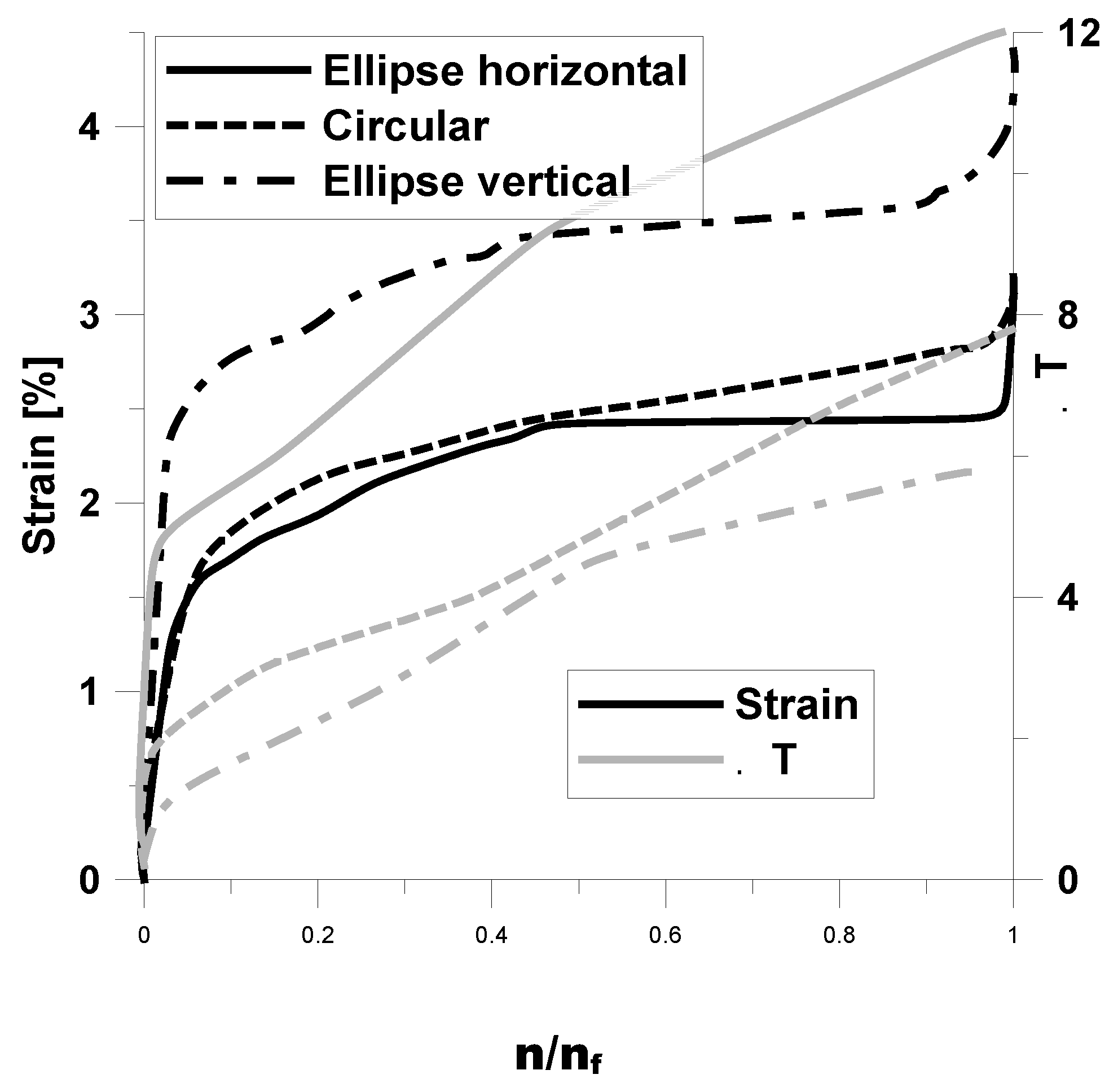
For unidirectional laminates, the plot of deformations versus the number of cycles (Figure 13) consists of three phases (stages), independently of the type of holes [10]: phase I—matrix cracking along fibers oriented at 45° and at −45° (splitting); phase II—splitting at four directions tangent to the hole and along fibers oriented at 45° and at −45° (the pattern “X”) with possible delaminations near the main directions of failure; phase III—delaminations and fiber debonding along the main directions of failure.
The slope of the initial part of the curve plotted in Figure 13 can be derived from the static tests since that part corresponds to the appearance of splits in the matrix. The first phase is a characteristic feature for the matrix-dominated angle-ply symmetric laminates. As demonstrated in Refs. [5,37,38], it does not occur for woven-roving laminates with circular and elliptical holes.
The initiation of the splitting cracks (the point A in Figure 13) at the four major directions (the “X” pattern) can be evaluated with the use of the plane strain energy-release criterion:
The broader discussion of the criterion and the form of the coefficients a and b can be found in Ref. [39].
The strain-life approach [5] is based on the observation that in many components the response of the material in a critical location is strain- or deformation-dependent. As reported in the literature, the strain-life approach is useful in evaluating the fatigue life of a notched component.
Due to the complexity of fatigue mechanisms, it is very difficult to characterize micro-damage in polymer composites in terms of deformation and stress state. To tackle this problem, it is customary to introduce a damage variable to characterize the fatigue-damage state. The damage variable d is generally described as a function of the maximum applied stress, a number of loading cycles n, load ratio R, and material properties such as stiffness E. Change in material stiffness, which has been adopted by many researchers, is utilized in this study to express fatigue damage in composite materials. The damage variable d is defined as:
However, the experimental results show that the measured Young’s modulus before complete failure is not equal to zero as it is plotted schematically in Figure 14. Since for an increasing number of cycles the experimental results demonstrated the linear behavior in the stress–strain diagrams (Figure 15), the value of Young’s modulus can be approximated as follows:
where the increments of strains are computed with the aid of Equation (1). Combining Equations (3) and (4) one can notice that the strain εy can be easily identified to the damage variable d.
From the superposition of the infrared thermography surface temperature data with that of the global effective strain data, it is possible to validate observations based on the coincidence of both the curves—Figure 16 (compare also with Figure 14). The increase in the temperature rise appears to agree well with evolution of the damage events, especially in view of three phases of monitored evolution of failure process.
Recording images of the speckled pattern from two cameras allowed out-of-plane displacements to be determined. In our opinion, the digital image correlation method would be helpful in the measurement of the global effective axial strains and their evolution with the number of cycles.
5. Concluding Remarks
The characteristics of damage accumulation in laminated panels with an open hole (circular and elliptical) are studied in this paper. The experimental results of damage growth show that there are three different phases (stages) during the damage evolution in composites under static or fatigue loading. During the first stage, damage grows rapidly due to the occurrence of multiple splits along fibers within the material of the panels. In the second phase, the damage increases steadily and slowly due to appearance of the “X” pattern of splitting cracks tangential to the hole edge and parallel to fiber directions. During the third (final) stage, the damage again grows rapidly due to delamination growth and the final fracture. Total displacements around the hole and deformation form obtained from the FE analysis were in good agreement with the experimental tests. Moreover, the FE analysis exhibited that global/local buckling under tension may occur due to the combined effects of tension and compression arising around the hole.
Infrared thermography gives both quantitative and qualitative mapping of the damage evolution in the different phases as well as information about the localization of splitting cracks and delaminations.
The structural health monitoring method strongly depends on the appropriate definition of paths where the response signals are monitored. Due to the random and scatter character of responses one can obtain general, qualitative information about the damage evolution in the form of the decrease of the amplitude and the increase of the phase.
The digital image correlation method is helpful in the evaluation of the strain distribution images on the surfaces of specimens. The increase of the strains can give both qualitative and quantitative information about the growth of cracks. The results obtained from digital image correlation are compared with the FE analysis. In the investigated example, good agreement for the experimental test and numerical solution is obtained.
The strain life-based model is proposed to control and monitor fatigue damage evolution. However, the accuracy and correctness of that model should be validated by further experimental investigations for various laminate configurations constituting a composite panel with an open hole.
Acknowledgments
The research project has been financed by National Science Center Poland pursuant to the decision No. DEC-2013/09/B/ST8/00178. The authors would like to thank B. Kiełbasa, Ł. Kowalczuk and P. Pastuszak for their help in conducting the experimental work.
Author Contributions
A.M. wrote the paper; M.C. prepared the infrared thermography analysis; P.R. provided the experiments and analyzed the fatigue tests results; A.S. conducted the DIC and SHM tests.
Conflicts of Interest
The authors declare no conflict of interest.
References
- McLaughlin, P.V., Jr.; Kulkarni, S.V.; Huang, S.N.; Walter Rosen, B. Fatigue of Notched Fiber Composite Laminates: Part 1. Analytical Model; NASA: Washington, DC, USA, 1975.
- T’ Hart, W.G.J. Residual Strength of (0, ±45)S And (±45, 0)S Carbon/Epoxy Laminates; Nationaal Lucht- en Ruimtevaartlaboratorium: Amsterdam, The Netherlands, 1977. [Google Scholar]
- Shokrieh, M.M. Failure of Laminated Composite Pinned Connections. M.Sc. Thesis, McGill University, Montreal, QC, Canada, 1991. [Google Scholar]
- Shokrieh, M.M.; Yazdi, M.H. A simplified approach to fatigue damage modelling of composite laminates with stress concentration: Regional elements model. Iran. Polym. J. 2009, 18, 233–246. [Google Scholar]
- Muc, A.; Romanowicz, P. Effect of notch on static and fatigue performance of multilayered composite structures under tensile loads. Compos. Struct. 2017, 178, 27–36. [Google Scholar] [CrossRef]
- Khan, A.I.; Venkataram, S.; Miller, I. Predicting fatigue damage of composites using strength degradation and cumulative damage model. J. Compos. Sci. 2018, 2, 9. [Google Scholar] [CrossRef]
- Khan, A.I.; Venkataraman, S.; Miller, I. Fatigue failure predictions of laminated composites using mechanical properties degradation and continuum damage models. In Proceedings of the AIAA/ASCE/AHS/ASC Structures, Structural Dynamics, and Materials Conference, Kissimmee, FL, USA, 8–12 January 2018. [Google Scholar]
- Degrieck, J.; Van Paepegem, W. Fatigue damage modelling of fibre-reinforced composite materials: Review. Appl. Mech. Rev. 2001, 54, 279–300. [Google Scholar] [CrossRef]
- Fatemi, A.; Yang, L. Cumulative fatigue damage and life prediction theories: A survey of the state of the art for homogeneous materials. Int. J. Fatigue 1998, 20, 9–34. [Google Scholar] [CrossRef]
- Krüger, H.; Rolfes, R. A physically based fatigue damage model for fibre-reinforced plastics under plane loading. Int. J. Fatigue 2015, 70, 241–251. [Google Scholar] [CrossRef]
- Sims, G.D. Fatigue test methods, problems and standards. In Fatigue in Composites; Harris, B., Ed.; Woodhead Publishing Ltd.: Sawston, UK, 2003; pp. 36–62. [Google Scholar]
- Kuhn, E.; Valot, E.; Herve, P. A comparison between thermosonics and thermography for delamination detection in polymer matrix laminates. Compos. Struct. 2012, 94, 1155–1164. [Google Scholar] [CrossRef]
- Kordatos, E.Z.; Aggelis, D.G.; Matikas, T.E. Monitoring mechanical damage in structural materials using complimentary NDE techniques based on thermography and acoustic emission. Compos. Part B 2012, 43, 2676–2686. [Google Scholar] [CrossRef]
- Zalameda, J.N.; Burke, E.R.; Horne, M.R.; Madaras, E.I. Large area nondestructive evaluation of a fatigue loaded composite structure. In Residual Stress, Thermomechanics & Infrared Imaging, Hybrid Techniques and Inverse Problems; Conference Proceedings of the Society for Experimental Mechanics Series; Quinn, S., Balandraud, X., Eds.; Springer: Cham, Switzerland, 2017; pp. 21–28. [Google Scholar]
- Maldague, X. Theory and Practice of Infrared Technology for Non Destructive Testing; John-Wiley & Sons: Hoboken, NJ, USA, 2001. [Google Scholar]
- Vavilov, V. Nondestructive testing handbook. In Book 1: Thermal/Infrared Testing; Spektr Publishing House: Moscow, Russia, 2009; Volume 5. [Google Scholar]
- Meola, C.; Boccardi, S.; Carlomagno, G.M. Infrared Thermography in the Evaluation of Aerospace Composite Materials; Woodhead Publishing Ltd.: Duxford, UK, 2017. [Google Scholar]
- Pastuszak, P.D.; Muc, A.; Barski, M. Methods of infrared non-destructive techniques: Review and experimental studies. In Advanced Materials in Machine Design; Muc, A., Barski, M., Kędziora, P., Eds.; Trans Tech Publications Ltd.: Zurich, Switzerland, 2013; pp. 131–141. [Google Scholar]
- Giurgiutiu, V. SHM of fatigue degradation and other in-service damage of aerospace composites. In Structural Health Monitoring of Aerospace Composites; Elsevier: London, UK, 2016; pp. 395–434. [Google Scholar]
- Muc, A.; Stawiarski, A. Identification of damages in composite multilayered cylindrical panels with delaminations. Compos. Struct. 2012, 94, 1871–1879. [Google Scholar] [CrossRef]
- Sutton, M.A.; Orteu, J.-J.; Schreier, H.W. Image Correlation for Shape, Motion and Deformation Measurements; Springer: New York, NY, USA, 2009. [Google Scholar]
- Khan, A.I. Progressive Failure Analysis of Laminated Composite Structures. Ph.D. Thesis, Virgiia Tech., Blacksburg, VA, USA, 2015. [Google Scholar]
- Tohgo, K.; Wang, A.S.D.; Chou, T.-W. A criterion for splitting crack initiation in unidirectional fiber-reinforced composites. J. Compos. Mater. 1993, 27, 1054–1076. [Google Scholar] [CrossRef]
- Bazhenov, S.L. Longitudinal splitting in unidirectional fibre-reinforced composites with an open hole. Compos. Sci. Technol. 1998, 58, 83–88. [Google Scholar] [CrossRef]
- Hu, J.; Zhang, K.; Cheng, H.; Liu, P.; Zou, P.; Song, D. Stress analysis and damage evolution in individual plies of notched composite laminates subjected to in-plane loads. Chin. J. Aeronaut. 2017, 30, 447–460. [Google Scholar] [CrossRef]
- Achard, V.; Bouvet, C.; Castanié, B.; Chirol, C. Discrete ply modelling of open hole tensile tests. Compos. Struct. 2014, 113, 369–381. [Google Scholar] [CrossRef] [Green Version]
- Kremer, T.; Schurmann, H. Buckling of tension-loaded thin-walled composite plates with cut-outs. Compos. Sci. Technol. 2009, 68, 90–98. [Google Scholar] [CrossRef]
- Krstulović-Opara, L.; Klarin, B.; Neves, P.; Domazet, Ž. Thermal imaging and thermoelastic stress analysis of impact damage of composite materials. Eng. Fail. Anal. 2011, 18, 713–719. [Google Scholar] [CrossRef]
- Lesinak, J.R.; Boyce, B.R.; Howenwater, G. Thermoelastic measurement under random loading. In Proceedings of the SEM Conference, Houston, TX, USA, 8 June 1998. [Google Scholar]
- Dulieu-Barton, J.M.; Quinn, S. Thermoelastic stress analysis of oblique holes in flat plates. Int. J. Mech. Sci. 1999, 41, 527–546. [Google Scholar] [CrossRef]
- Bindal, V.N. Transducers for Ultrasonic Flaw Detection; Narosa Press: New Delhi, India, 1999. [Google Scholar]
- He, J.; Ran, Y.; Liu, B.; Yang, J.; Guan, X. A fatigue crack size evaluation method based on lamb wave simulation and limited experimental data. Sensors 2017, 17, 2097. [Google Scholar] [CrossRef] [PubMed]
- Ambu, R.; Aymerich, F.; Bertolino, F. Investigation of the effect of damage on the strength of notched composite laminates by digital image correlation. J. Strain Anal. 2005, 40, 294–302. [Google Scholar] [CrossRef]
- Helm, J.; Kurts, S. Digital image correlation-based experimental stress analysis of reinforced concrete beams, strengthened using carbon composites. SPIE-IS&T 2005, 5665, 40–50. [Google Scholar]
- Lagattu, F.; Brillaud, J.; Lafarie-Frenot, M.-C. High strain gradient measurements by using digital image correlation technique. Mater. Charact. 2004, 53, 17–28. [Google Scholar] [CrossRef]
- Xu, J.; Lomov, S.V.; Verpoest, I.; Daggumati, S.; Van Paepegem, W.; Degrieck, J. A comparative study of twill weave reinforced composites under tension–tension fatigue loading: Experiments and meso-modelling. Compos. Struct. 2016, 135, 306–315. [Google Scholar] [CrossRef]
- Durchlaub, E.C.; Freeman, R.B. Design Data for Composite Structure Safe life Prediction; Technical Report AFML-TR-73–225; Air Force Materials Laboratory: Dayton, OH, USA, 1974. [Google Scholar]
- Hallett, S.R.; Jiang, W.-G.; Khan, B.; Wisnom, M.R. Modelling the interaction between matrix cracks and delamination damage in scaled quasi-isotopic specimens. Compos. Sci. Technol. 2008, 68, 80–90. [Google Scholar] [CrossRef]
- Romanowicz, P.; Składanowska, K.; Muc, A. Fracture strength of multi-layered composite plates with circular delamination. In Proceedings of the International Conference on Electrical Engineering and Automation (ICEEA 2016), Xiamen, China, 18–19 December 2016. [Google Scholar]
Figure 1.
Fatigue-testing machine with equipment for damage-growth monitoring.

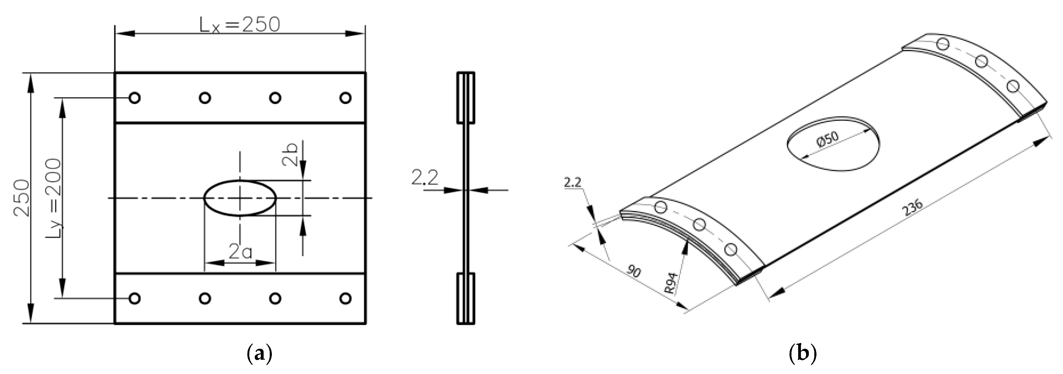
Figure 2.
Dimensions (mm) of the specimens (a) and (b) used in the static and fatigue loading tests.
Figure 2.
Dimensions (mm) of the specimens (a) and (b) used in the static and fatigue loading tests.

Figure 3.
The stress–strain diagrams and photographs of failure modes for unidirectional specimens under tensile loading.
Figure 3.
The stress–strain diagrams and photographs of failure modes for unidirectional specimens under tensile loading.
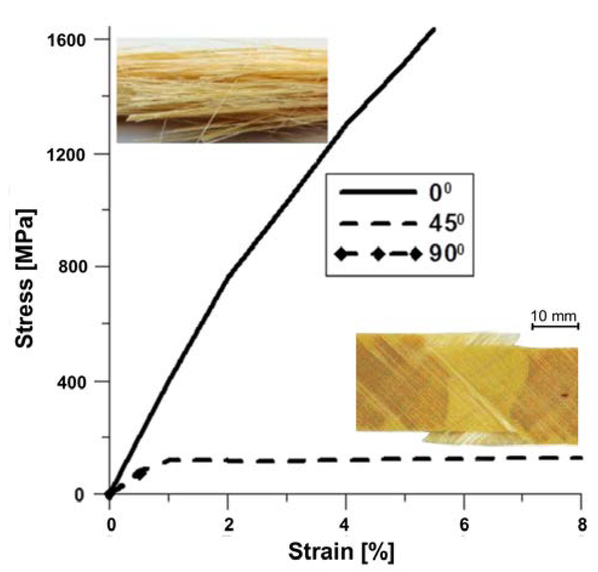
Figure 4.
Static deformations of rectangular panels with elliptical holes.
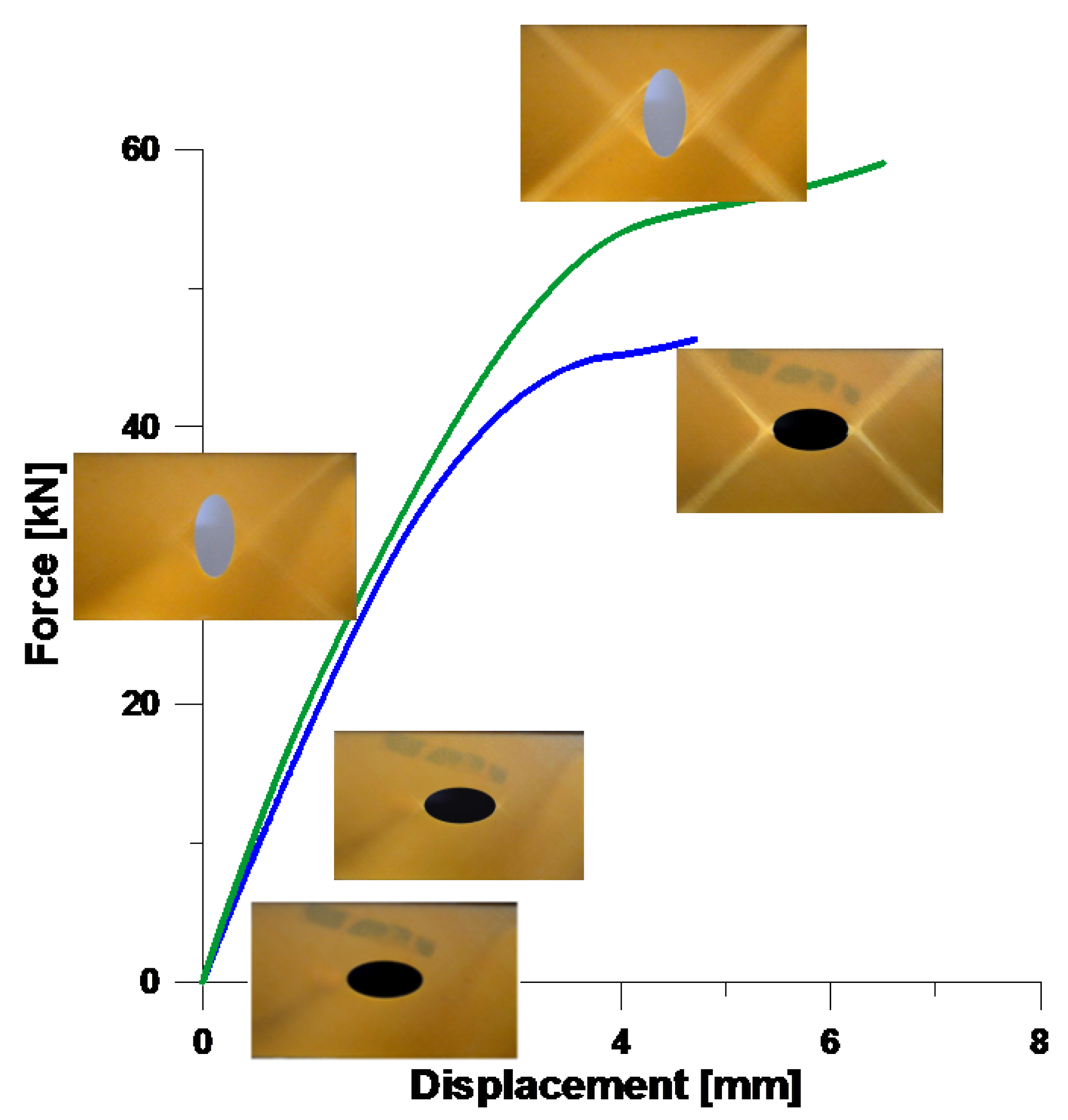
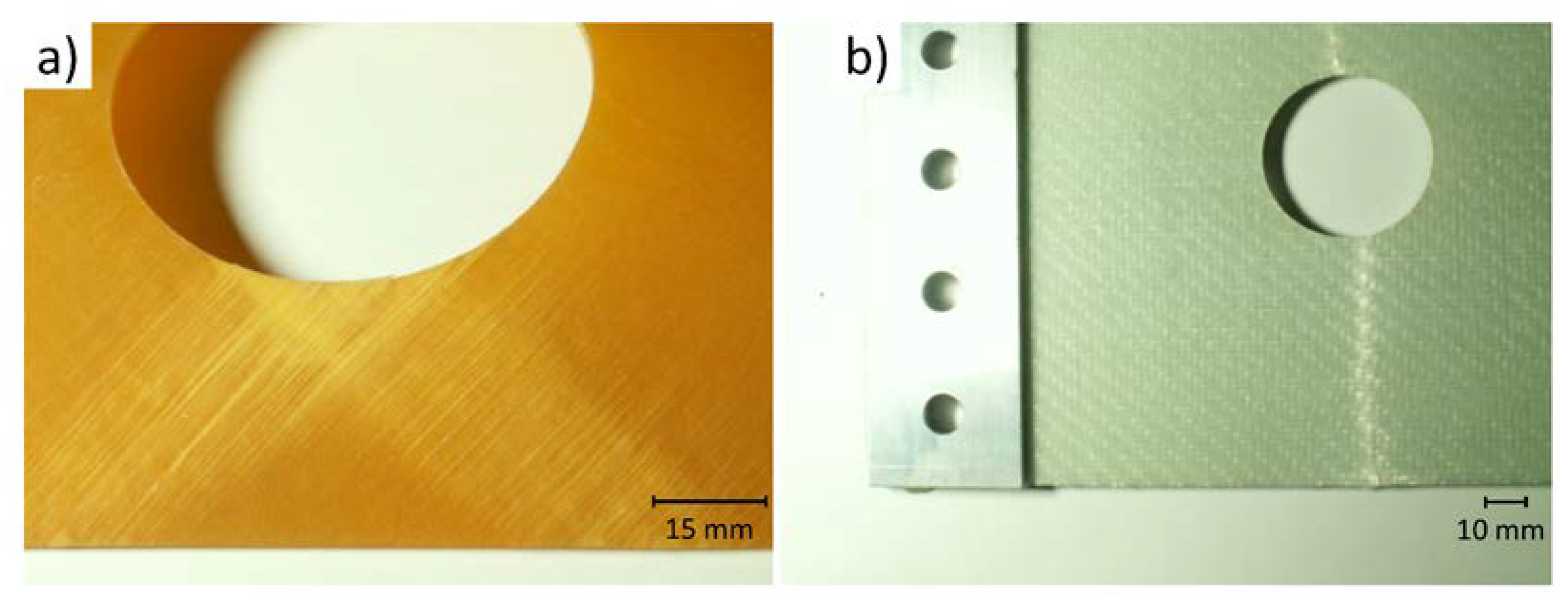
Figure 5.
Photographs of cracks in composite panels: (a) shallow cylindrical panel [+45°/−45°]4; (b) plate made of woven-roving fabric.
Figure 5.
Photographs of cracks in composite panels: (a) shallow cylindrical panel [+45°/−45°]4; (b) plate made of woven-roving fabric.

Figure 6.
Undeformed (blue) and deformed (red) distributions of total displacements around the hole—the finite element analysis (not to scale): (a) vertical ellipse; (b) circular; (c) horizontal ellipse.
Figure 6.
Undeformed (blue) and deformed (red) distributions of total displacements around the hole—the finite element analysis (not to scale): (a) vertical ellipse; (b) circular; (c) horizontal ellipse.

Figure 7.
Rise of temperatures Δt at the edges of holes s: (a) the vertical elliptical hole (Δtmax = 8.2 °C; (b) the horizontal elliptical hole (Δtmax = 5.8 °C; (c) the circular hole (Δtmax = 8 °C).
Figure 7.
Rise of temperatures Δt at the edges of holes s: (a) the vertical elliptical hole (Δtmax = 8.2 °C; (b) the horizontal elliptical hole (Δtmax = 5.8 °C; (c) the circular hole (Δtmax = 8 °C).

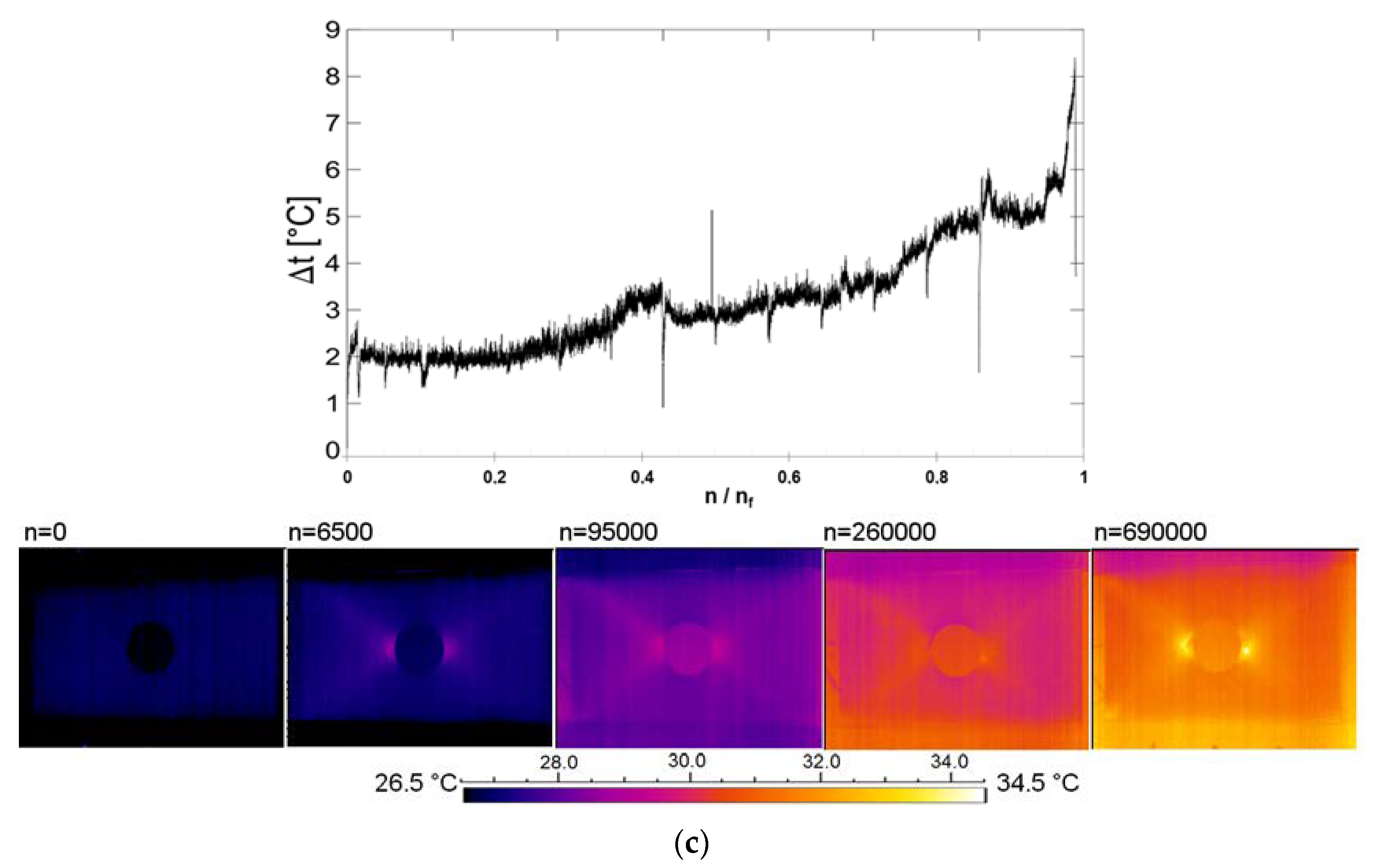
Figure 8.
The schema of the excitation signal used and an example of the possible Lamb-wave response.
Figure 8.
The schema of the excitation signal used and an example of the possible Lamb-wave response.

Figure 9.
The signal responses at various stages of the fatigue damage (the sensor numbers are explained below in Figure 10).
Figure 9.
The signal responses at various stages of the fatigue damage (the sensor numbers are explained below in Figure 10).
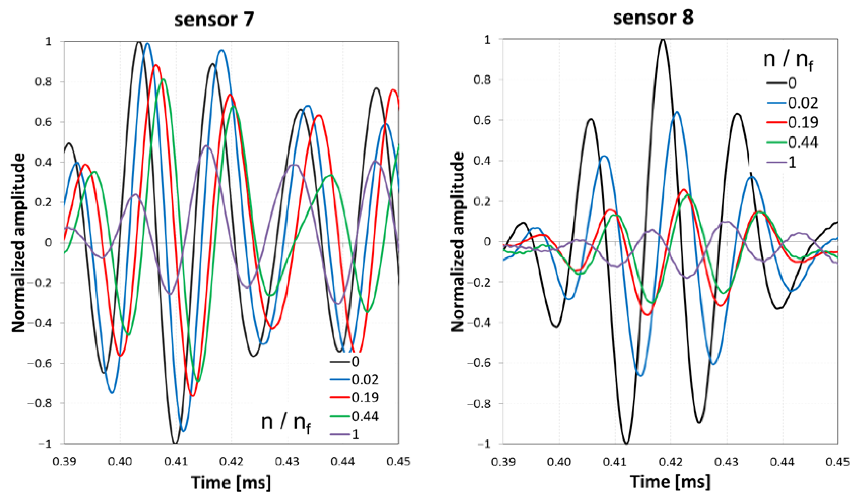
Figure 10.
Configurations of actuators and sensors (the piezoelectric (PZT) disks for vertical (a) and horizontal (b) elliptical hole are visible as dark shadows in Figure 4)—the red dotted lines show the directions of cracks at 45° or −45°.
Figure 10.
Configurations of actuators and sensors (the piezoelectric (PZT) disks for vertical (a) and horizontal (b) elliptical hole are visible as dark shadows in Figure 4)—the red dotted lines show the directions of cracks at 45° or −45°.

Figure 11.
Comparison of the approximated amplitudes and phases: (a) vertical ellipse, (b) horizontal ellipse.
Figure 11.
Comparison of the approximated amplitudes and phases: (a) vertical ellipse, (b) horizontal ellipse.
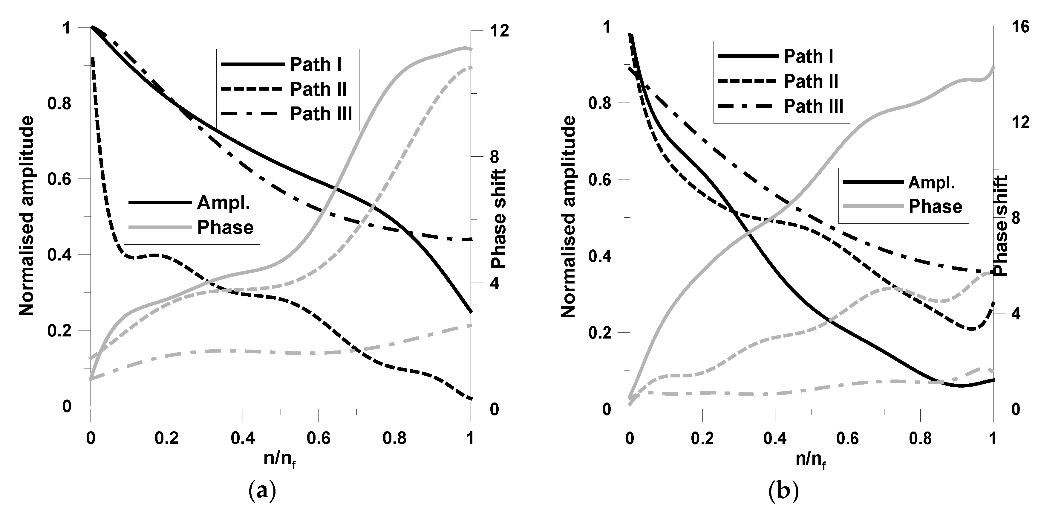
Figure 12.
Area monitored by digital-image correlation (DIC) (a) and finite element (FE) simulation (b)—woven-roving composite.
Figure 12.
Area monitored by digital-image correlation (DIC) (a) and finite element (FE) simulation (b)—woven-roving composite.
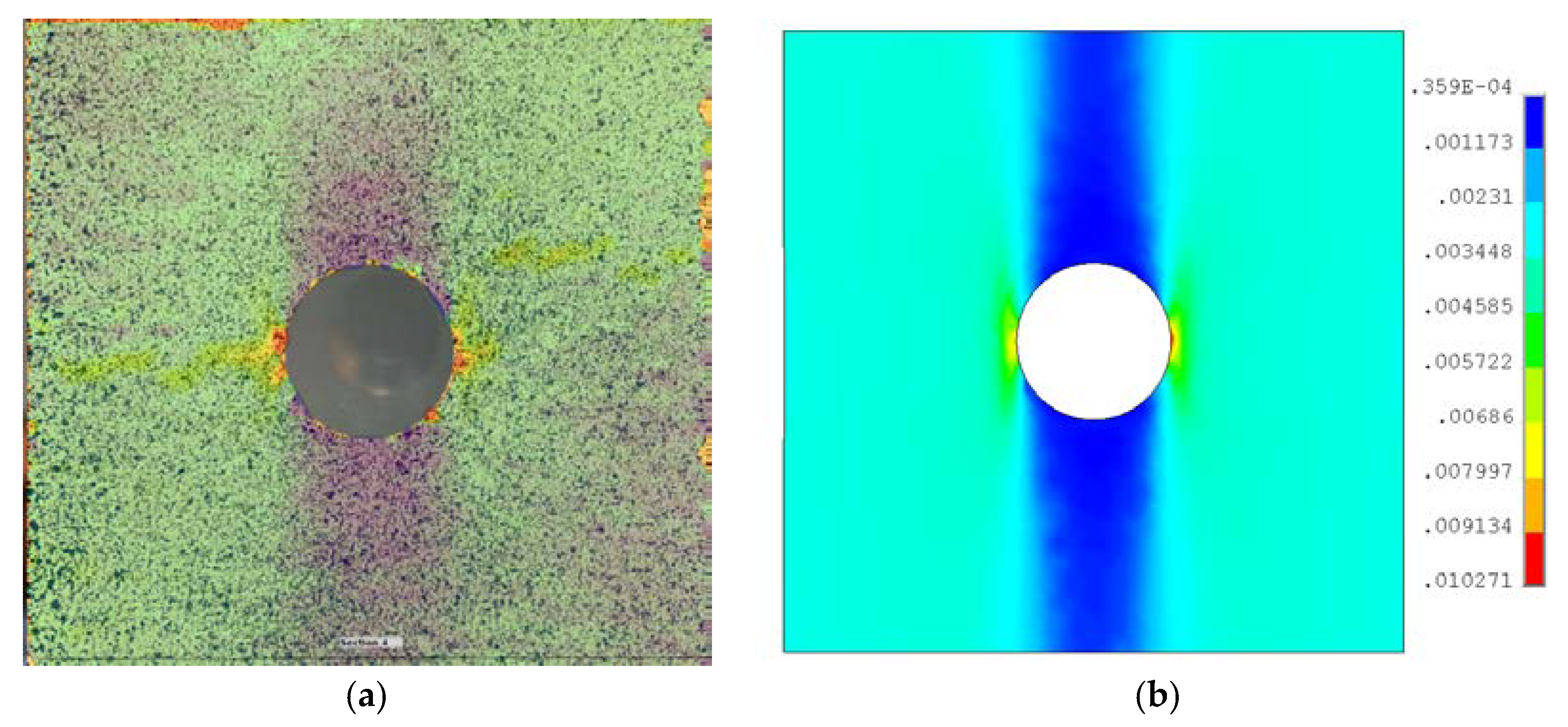
Figure 13.
The strain-life curve for structures with holes; the strain corresponds to the total strain of the plate, i.e., ε = (Ly − Ly0)/Ly0 where Ly—the actual plate length and Ly0—the initial plate length.
Figure 13.
The strain-life curve for structures with holes; the strain corresponds to the total strain of the plate, i.e., ε = (Ly − Ly0)/Ly0 where Ly—the actual plate length and Ly0—the initial plate length.
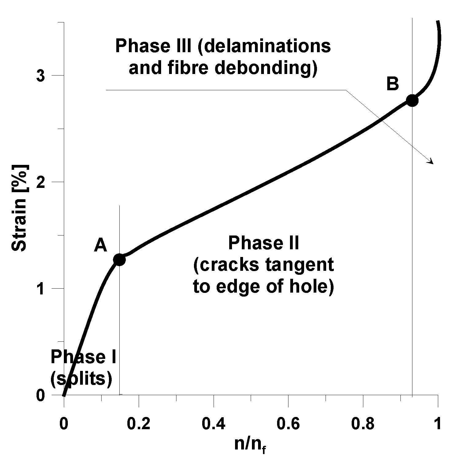
Figure 14.
Variations of the global plate Young’s modulus versus the number of cycles.
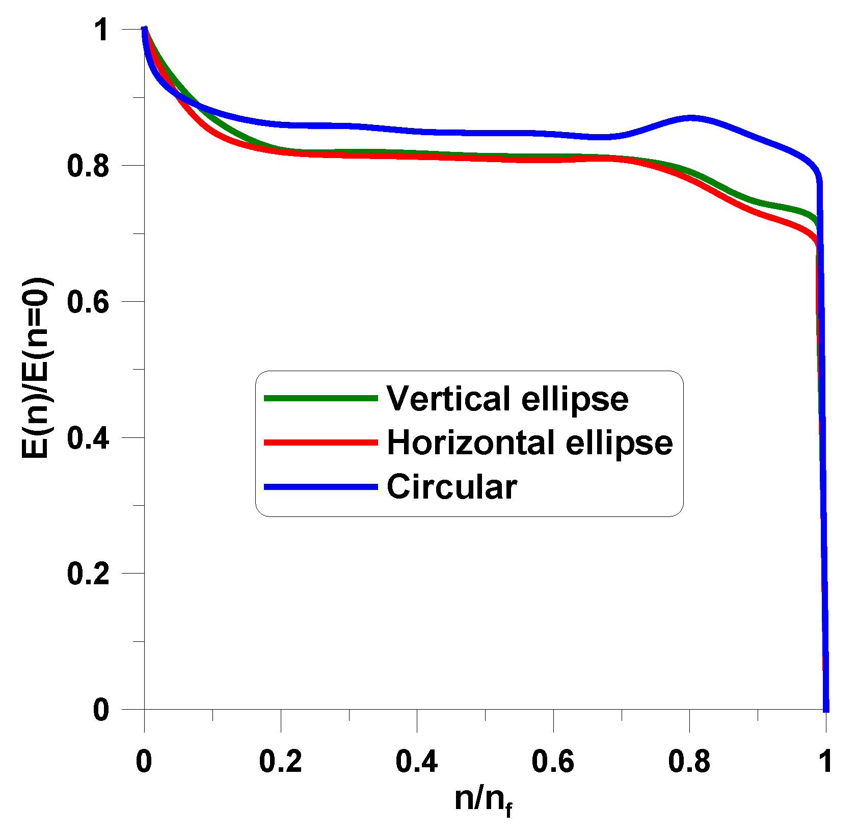
Figure 15.
Global fatigue deformations of the plate with the vertical elliptical hole.
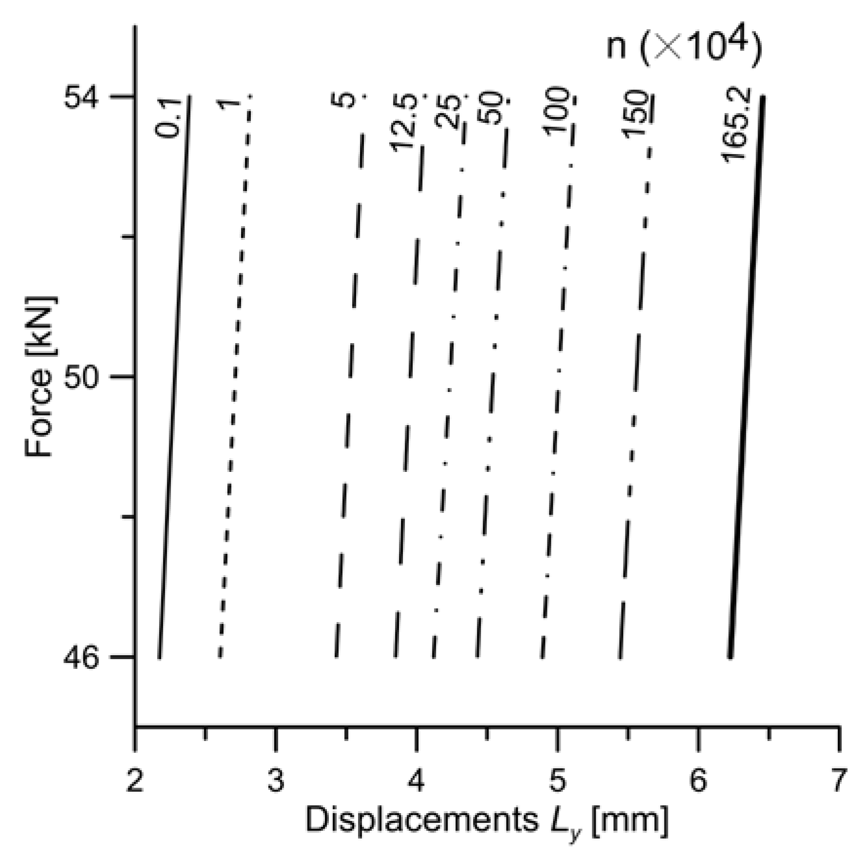
Figure 16.
Variations of the global effective strains and the temperature rise with the normalized number of cycles.
Figure 16.
Variations of the global effective strains and the temperature rise with the normalized number of cycles.

Table 1.
Fatigue loading conditions.
| Hole | Circular a = b = 25 mm | Circular a = b = 25 mm | Elliptical Vertical a = 17.5, b = 35.7 mm | Elliptical Horizontal a = 35.7, b = 17.5 mm |
|---|---|---|---|---|
| Material | Woven-roving glass/epoxy | Unidirectional glass/epoxy | ||
| Stress ratio | 0.818 | 0.833 | 0.852 | 0.810 |
| Frequency (Hz) | 15 | 15 | 30 | 30 |
| Mean load (kN) | 40 | 44 | 50 | 38 |
| Amplitude (kN) | 4 | 4 | 4 | 4 |
Table 2.
Mechanical properties and fiber directions of the tested specimens—“0°” means the warp direction.
Table 2.
Mechanical properties and fiber directions of the tested specimens—“0°” means the warp direction.
| Materials | Fiber Direction | E1 (GPa) | E2 (GPa) | G12 (GPa) | ν12 |
|---|---|---|---|---|---|
| Unidirectional glass/epoxy | ±45° | 46.4 | 14.9 | 5.2 | 0.27 |
| Woven-roving fabric glass/epoxy | 0° | 62 | 62 | 7.8 | 0.26 |
© 2018 by the authors. Licensee MDPI, Basel, Switzerland. This article is an open access article distributed under the terms and conditions of the Creative Commons Attribution (CC BY) license (http://creativecommons.org/licenses/by/4.0/).
Share and Cite
MDPI and ACS Style
Muc, A.; Chwał, M.; Romanowicz, P.; Stawiarski, A. Fatigue-Damage Evolution of Notched Composite Multilayered Structures under Tensile Loads. J. Compos. Sci. 2018, 2, 27. https://doi.org/10.3390/jcs2020027
AMA Style
Muc A, Chwał M, Romanowicz P, Stawiarski A. Fatigue-Damage Evolution of Notched Composite Multilayered Structures under Tensile Loads. Journal of Composites Science. 2018; 2(2):27. https://doi.org/10.3390/jcs2020027
Chicago/Turabian StyleMuc, Aleksander, Małgorzata Chwał, Paweł Romanowicz, and Adam Stawiarski. 2018. "Fatigue-Damage Evolution of Notched Composite Multilayered Structures under Tensile Loads" Journal of Composites Science 2, no. 2: 27. https://doi.org/10.3390/jcs2020027