Article

Fibre Length Reduction in Natural Fibre-Reinforced Polymers during Compounding and Injection Moulding—Experiments Versus Numerical Prediction of Fibre Breakage

1
Hochschule Bremen—City University of Applied Sciences Bremen, Biomimetics—The Biological Materials Group, Neustadtswall 30, 28199 Bremen, Germany
2
Polymer Engineering Center (PEC), University of Wisconsin-Madison, 1513 University Avenue, Madison, WI 53706, USA
3
M-Base Engineering + Software GmbH, Dennewartstr. 27, 52068 Aachen, Germany
4
VKT Video Kommunikation GmbH, Sandwiesenstr. 15, 72793 Pfullingen, Germany
5
Friedrich-Alexander-Universität Erlangen-Nürnberg, Martensstrasse 9, 91058 Erlangen, Germany
*
Author to whom correspondence should be addressed.
J. Compos. Sci. 2018, 2(2), 20; https://doi.org/10.3390/jcs2020020
Submission received: 22 February 2018 / Revised: 23 March 2018 / Accepted: 26 March 2018 / Published: 28 March 2018
(This article belongs to the Special Issue Discontinuous Fiber Composites)

Abstract

:
To establish injection-moulded, natural fibre-reinforced polymers in the automotive industry, numerical simulations are important. To include the breakage behaviour of natural fibres in simulations, a profound understanding is necessary. In this study, the length and width reduction of flax and sisal fibre bundles were analysed experimentally during compounding and injection moulding. Further an optical analysis of the fibre breakage behaviour was performed via scanning electron microscopy and during fibre tensile testing with an ultra-high-speed camera. The fibre breakage of flax and sisal during injection moulding was modelled using a micromechanical model. The experimental and simulative results consistently show that during injection moulding the fibre length is not reduced further; the fibre length was already significantly reduced during compounding. For the mechanical properties of a fibre-reinforced composite it is important to overachieve the critical fibre length in the injection moulded component. The micromechanical model could be used to predict the necessary fibre length in the granules.

1. Introduction

Increasing environmental consciousness leads to new developments in material selection and use. Natural fibre-reinforced compounds (NFC) are a good solution to combine renewable resources with light-weight constructions. Much research has been done to determine the mechanical properties of NFCs, demonstrating interesting potential for different applications [1,2,3,4,5,6,7]. The injection-moulding process is a conventional technique in the automotive industry for short fibre-reinforced polymers in large-scale productions, mostly using glass fibres. A new focus is now to also use natural fibre-reinforced injection-moulded polymers. Among others, there are two important factors influencing the mechanical properties of NFCs: the fibre orientation and the fibre morphology (fibre length and aspect ratio) [8,9,10,11]. Therefore, it is very important to determine the fibre orientation and to understand the fibre breakage behaviour during processing. Further numerical simulations are necessary to help establish injection-moulded NFCs in the automotive industry. First, successful research steps were taken to perform injection-moulding simulations with NFCs [12,13,14,15,16,17]. To include the fibre breakage behaviour of natural fibres in commercial injection moulding simulations further research is necessary. Fibre damage takes place during the two process steps, compounding and injection moulding, and are a result of the following:
  • fibre-fibre interaction;
  • fibre-matrix interaction (Figure 1); and
  • fibre-wall interaction [11,18].
The fibre-fibre interaction resulting from collision, spatial hindrance, and friction leads to fibre bending, which may result in fibre breakage. The fibre-fibre interaction is strongly correlated with the fibre mass content in the polymer [19]. The fibre-matrix interaction occurs mostly due to the fact that the outer part of granules is melting faster than the inner part. The fibres often stick out of the solid polymer and high viscous polymer melt flows around; so the fibres are bent, buckled, and sheared off, which can result in fibre breakage (Figure 1) [10,11]. A mathematical approach dealing with fibre instability phenomena, like fibre kinking and fibre splitting, was provided by Merodio and Ogden [20,21].
Since the fibre morphology influences both the flow behaviour in the polymer melt and mechanical properties of the component, it is important to be able to predict fibre breakage. A mechanistic model can be used to simulate single fibres in a polymer melt and to predict fibre breakage. But till now, a mechanistic model has not been used to predict lignocellulosic fibre breakage accurately [22].
For glass fibres extensive research effort was done to analyse fibre breakage during compounding and injection moulding [23]. Several techniques to measure fibre length reduction after processing have been developed [24,25,26,27,28,29,30,31]. The first step for all techniques is the separation of the fibre from the matrix. For glass fibres the most common way is to burn off the polymer [24,25,26,27,28]. Another way is to extract the fibre with a suitable solvent [30,31,32]. For NFCs it is not possible to burn off the matrix without burning the natural fibres as well. Therefore, an appropriate solvent is necessary to dissolve the matrix without destroying the fibres.
During compounding of glass fibres with a polymer lower screw speed, higher barrel temperature and lower mixing times lead to higher average fibre lengths [23]. For injection moulding lower back pressure, lower injection speed, and more generous gate and runner dimensions lead to higher average fibre lengths [23]. Ramani et al. (1995) showed that most of the fibre length reduction occurs in the mixing section of an extruder [30]. The increase of the fibre mass content from 30% to 40% glass fibres led to higher damage due to higher fibre-fibre interactions [30]. Another important influence on final fibre length is the viscosity of the matrix; a higher viscosity leads to lower average fibre lengths [18].
In contrast to glass fibres, natural fibres (when fibre bundles are used) do not only break (length reduction) but also split (thickness reduction) during processing. Natural fibres are not single fibres, such as glass or carbon fibres, but they occur mostly as fibre bundles. For natural fibres it is of importance to distinguish between the term fibre (single cell) and fibre bundle (several fibres sticking together by pectin substances) [33,34,35].
Furthermore, the different natural fibre types have different damage behaviour. Recent research activities can be found in literature determining the different breakage mechanisms of flax, sisal, hemp, and miscanthus [22,36,37].
Castellani et al. (2016) found three main mechanisms to differ the fibre breakage behaviour of lignocellulosic fibres:
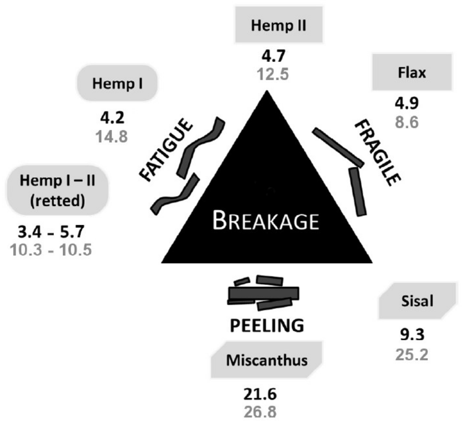
  • “Fatigue-driven breakage: elements bend many times and then break”
  • “Fragile behaviour: rigid elements bend and break”
  • “Peeling: chunks are removed from fibre bundles” [36].
In Figure 2 the different breakage mechanisms are shown for retted and unretted hemp, sisal, flax, and miscanthus. Further studies assume that the initiation of flax and hemp fibre breakage is related to dislocations or also called “kink bands” [38,39,40]. Dislocations are defects which are produced during the extraction of fibres out of the stem [38,41,42].
Steuernagel et al. (2013) found an interesting aspect for natural fibres as reinforcement, even with respect to recycling, due to the fact that the fibre bundles not only break, but also split [43]. Hence, one can assume that the aspect ratio can increase during compounding, which can result in higher mechanical properties [43], while glass fibres maintain their thickness and only reduce in length during recycling processes. Due to the splicing of the natural fibres, the surface area increases and a higher interaction with the matrix can be achieved [43].
In the present study the fibre length and thickness reduction of flax and sisal fibre bundles shall be analysed during compounding and injection moulding. Furthermore, a micromechanical model, which was developed for glass fibres, was adapted to predict fibre breakage during injection moulding of flax and sisal fibre bundles in a polypropylene matrix. Therefore, the following research hypotheses were tested:
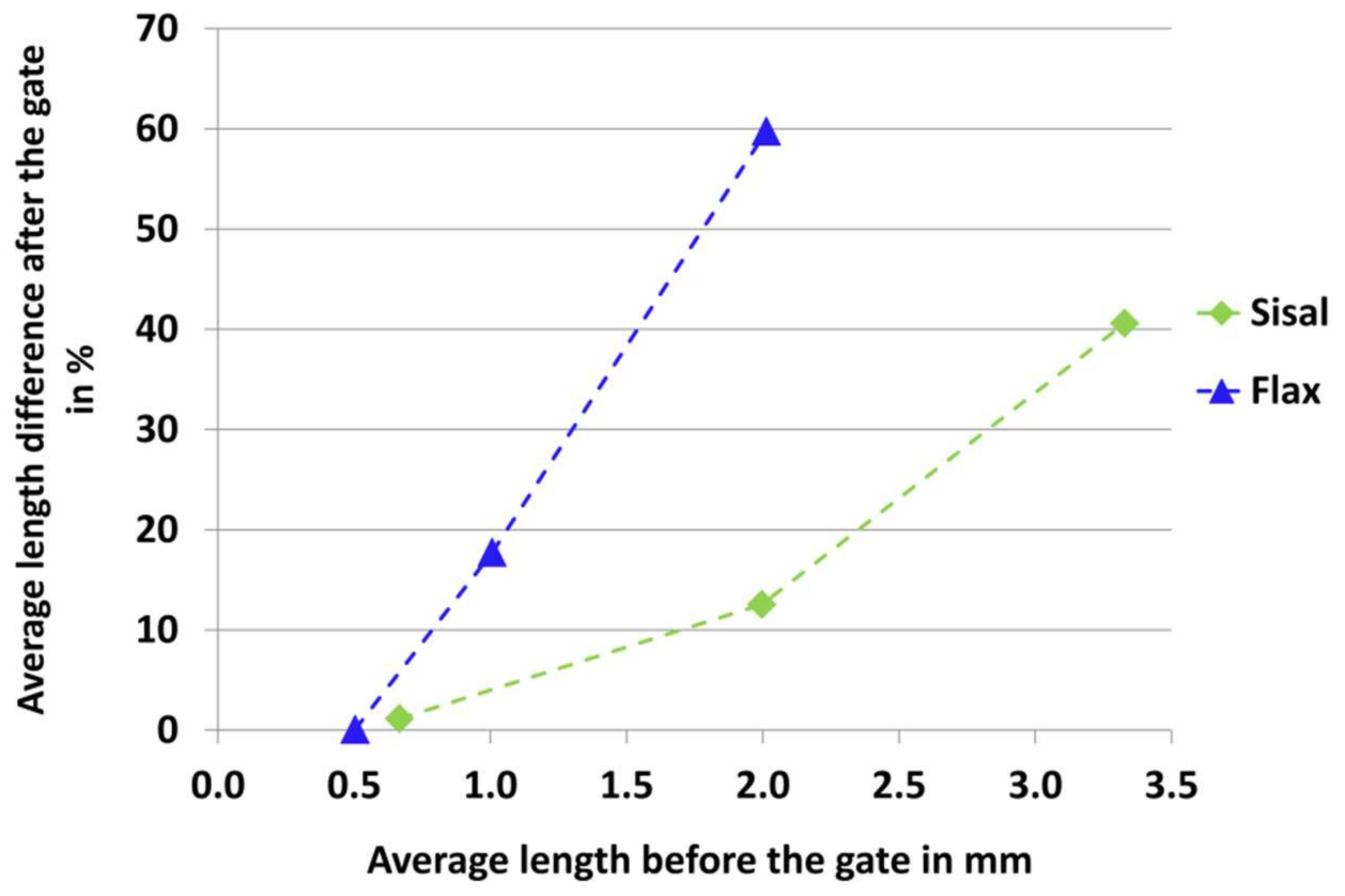
  • During the two process steps, compounding and injection moulding, the fibre length and fibre width of sisal and flax is significantly reduced.
  • The mechanistic model can predict the real fibre length reduction and can be used as a product development tool to determine the necessary fibre length in the compound to overachieve the critical fibre length in the injection-moulded component.

2. Materials and Methods

2.1. Fibres and Matrix

Chopped sisal (Agave sisalana P.) fibre bundles were purchased for this study from Cayetano Garcia Del Moral S.L. (Cabra del Santo Cristo, Spain; harvest year: 2012). To guarantee a homogenous fibre dosing the fibres were pelletized by BaVe-Badische Faserveredelung GmbH (Malsch, Germany). Flax (Linum usitassimum L.). Fibre bundles were harvested in 2010 in the Netherlands and also pelletized by BaVe-Badische Faserveredelung GmbH before compounding. Subsequently, the used terms “sisal” and “flax” refer to fibre bundles of sisal and flax, extracted from the leaves of Agave sisalana P. and the stems of Linum usitassimum L., respectively. With both fibre types, compounds with 30 mass% fibres and a polypropylene (PP) (Moplen EP 500 V, LyondellBasell, Frankfurt, Germany) were produced with a twin screw extruder (ZE 34 Basic, KraussMaffei Berstorff GmbH, Hanover, Germany) at the IfBB (Hochschule Hanover, Germany). For a better adhesion between the natural fibres and the matrix, a coupling agent was used with a dosage of 3 wt% (SCONA TPPP 8112 FA, BYK-Chemie GmbH, Wesel, Germany). Furthermore, plates (30 × 16 × 3 mm3) were produced with a multi-tool injection mould on a KM 160-750 EX machine (KraussMaffei Technologies GmbH, Munich, Germany) at IfBB. The compounding and injection moulding process parameters are described in more detail in [44].

2.2. Fibre Extraction

To observe the morphological change of sisal and flax during the two process steps, compounding and injection moulding, the fibre bundles were extracted out of the PP matrix. The natural fibres were extracted with an organic solvent out of the granules and the injection-moulded plates. This procedure is described in more detail in [45].

2.3. Fibre Morphology Analysis (SEM and Fibre Shape)

The fibre morphology of sisal and flax was analysed before the compounding, after the compounding (extracted from the granules) and after injection moulding (extracted from the plates).
First, the fibre bundles were investigated optically using a JSM-6510 scanning electron microscope (SEM) (JEOL GmbH, Eching, Germany) at an acceleration voltage of 2 kV. Before the investigation, sisal and flax were coated with a thin conductive gold layer for 60 s under a current of 56 mA using a Bal-Tec sputter coater type SCD 005 (Bal-Tec AG, Balzers, Liechtenstein).
Second, the length and width of sisal and flax were analysed by the image analysis software FibreShape 5.1.1 (IST AG, Vilters, Switzerland). Therefore, the original flax and sisal fibre bundles were scanned with an Epson Perfection V700 photo scanner (Seiko Epson Corperation, Suwa, Japan) with a resolution of 1200 dpi. The smaller, extracted fibre bundles were prepared on slide frames (40 × 40 mm2, glass width of 2 mm; Gepe, Zug, Switzerland) and scanned with a Canonscan CS 4000scanner (Canon, New York, NY, USA) with a resolution of 4000 dpi. Before scanning, all samples were conditioned for at least 24 h at 20 °C and 65% relative humidity according to DIN EN ISO 139.

2.4. Statistics

The statistical analysis of the Fibre Shape results was done by the programme “R” Version 3.4.0. Kolmogorov-Smirnov-Lilliefors tests (sample size > 700) were performed to evaluate the data regarding a normal distribution with a level of significance of α = 0.05. To prove if the fibre bundles were significantly damaged during the processes, Wilcoxon-Mann-Whitney tests were performed with a level of significance of α = 0.01. This non-parametric test was chosen due to the fact that the data are not normally distributed and the samples are considered to be unpaired. For large sample sizes even small differences in the data distributions might lead to significant differences. Therefore, the effect size was determined, which is a quantitative measure of the strength of a phenomenon, according to [46,47]. In this study it was measured if the two process steps have none, a small, an intermediate, or a large effect on the change of the fibre morphology.
Even if the distributions of the length and width values are not normally distributed, the mean values were used for the simulation with the mechanistic model. The arithmetic mean is a location parameter for metrically scaled variables, whereas the median is a location parameter for ordinal scaled variables. The ordinal scale refers to measurements that can be ordered in terms of “greater”, “less”, or “equal”; therefore it is also called rank scale, whereas the metric scale allows to determine the magnitude of differences between the measured values. [48].

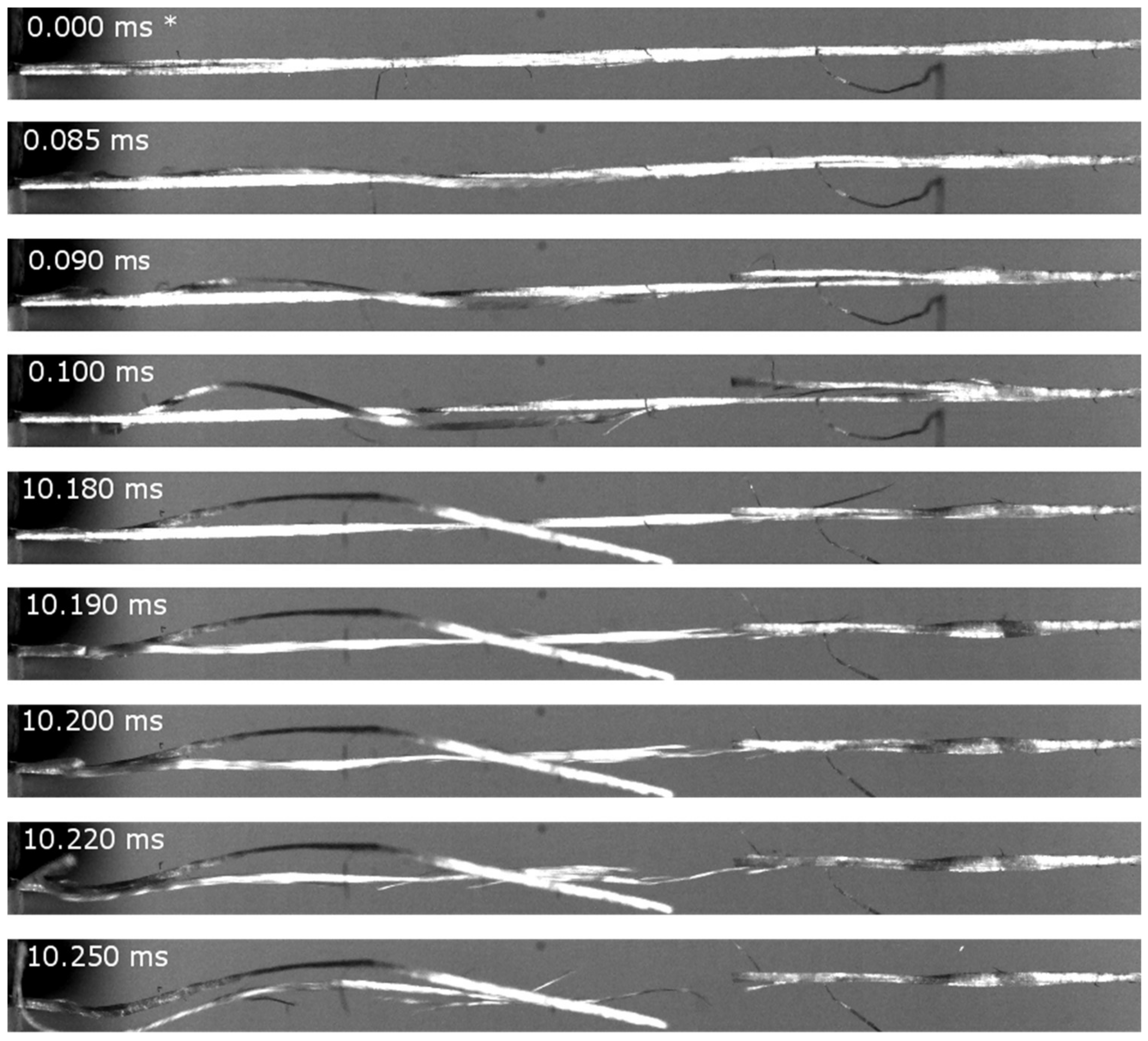
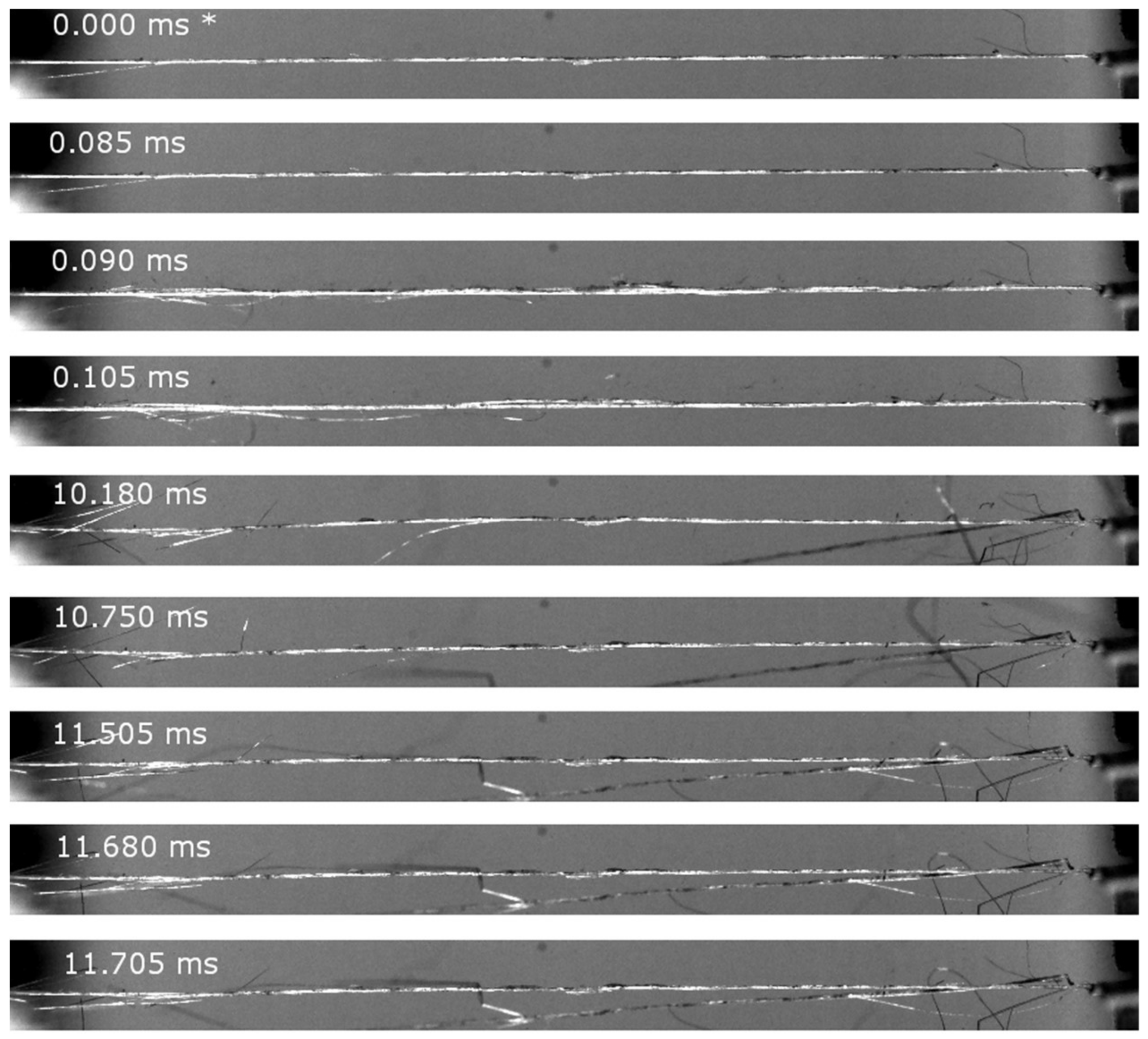
2.5. Ultra-High-Speed Camera

An ultra-high-speed camera (FASTCAM SA-Z type 2100K-M-32GB-FD, Photron, Tokyo, Japan) was used to optically analyse the differences in the breaking behaviour of flax and sisal. During a tensile test of the fibres bundles, pictures were taken with 200,000 frames per second. The tensile tests were performed with a Fafegraph M testing machine (Textechno, Mönchengladbach, Germany) with a testing speed of 20 mm/s at a gauge length of 20 mm working with a pneumatic clamping system (PVC/PMMA clamps) until the fibres totally failed.

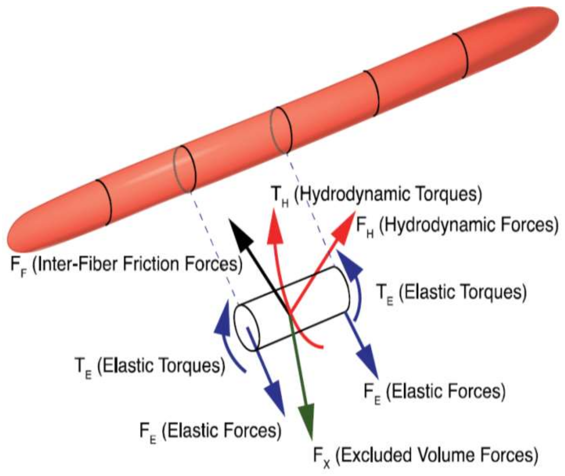
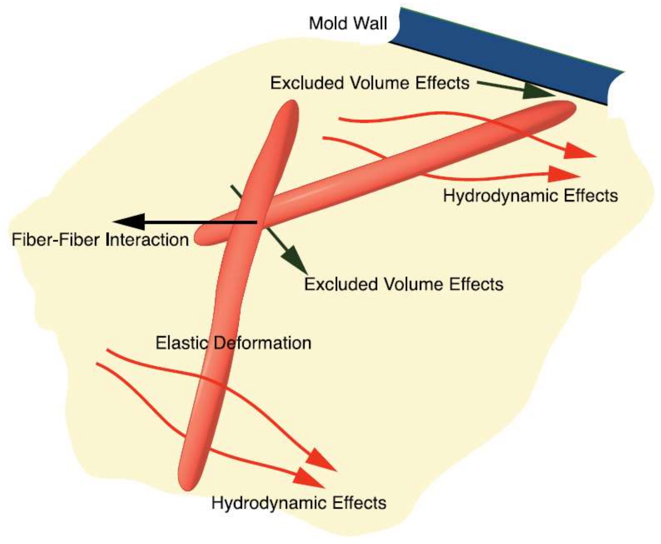
2.6. Micromechanical Model

The micromechanical or mechanistic model, which was used in this study, is a particle level simulation and represents each fibre as a chain of segments interconnected by spherical joints. For each time step the force and torque balance are performed on each element of the object (Figure 3, Equations (1) and (2)):
k = 1 N v F i k v + F i c F i + 1 c + j = 1 N b F i j h = 0
M i b M i + 1 b r i × F i + k c + k = 1 N v r i k × F i k v + j = 1 N b [ T i j h + r i j × F i j h ] = 0
where F i k v is a force due to the contact between the rods i and k, M i b   and M i + 1 b are moments due to bending, N v is the number of rods which are in contact with rod i, and N b is the number of beads in rod i.
The segments experience hydrodynamic effects, fibre-fibre interaction and fibre flexibility, but the model excludes volume effects due to fibre-fibre and fibre-wall contacts (Figure 4). The micromechanical model is used to determine the fibre interaction coefficients for fibre-reinforced polymers. Further it can also predict fibre breakage behaviour in polymer melts, if the mechanical properties of the fibres are known. In a shear cell the forces and interactions are calculated to predict the fibre interaction coefficient CI and the fibre breakage. In this study, a cluster of fibres in a shear cell is modelled while the fibres flow through the gate of a mould. The commercial computational fluid dynamics software COMSOL Multiphysics® (COMSOL AB, Stockholm, Sweden) was used. The CFD simulation used a non-Newtonian viscosity represented with a Bird-Carreau model [49]. Before the shear flow modelling, the fibre cluster needs to be precompressed until the desired fibre density, representing the real fibre volume, is reached. The mechanistic model and the exact procedure to determine the CI for flax/PP and sisal/PP are described in more detail in [50,51,52].

3. Results and Discussion

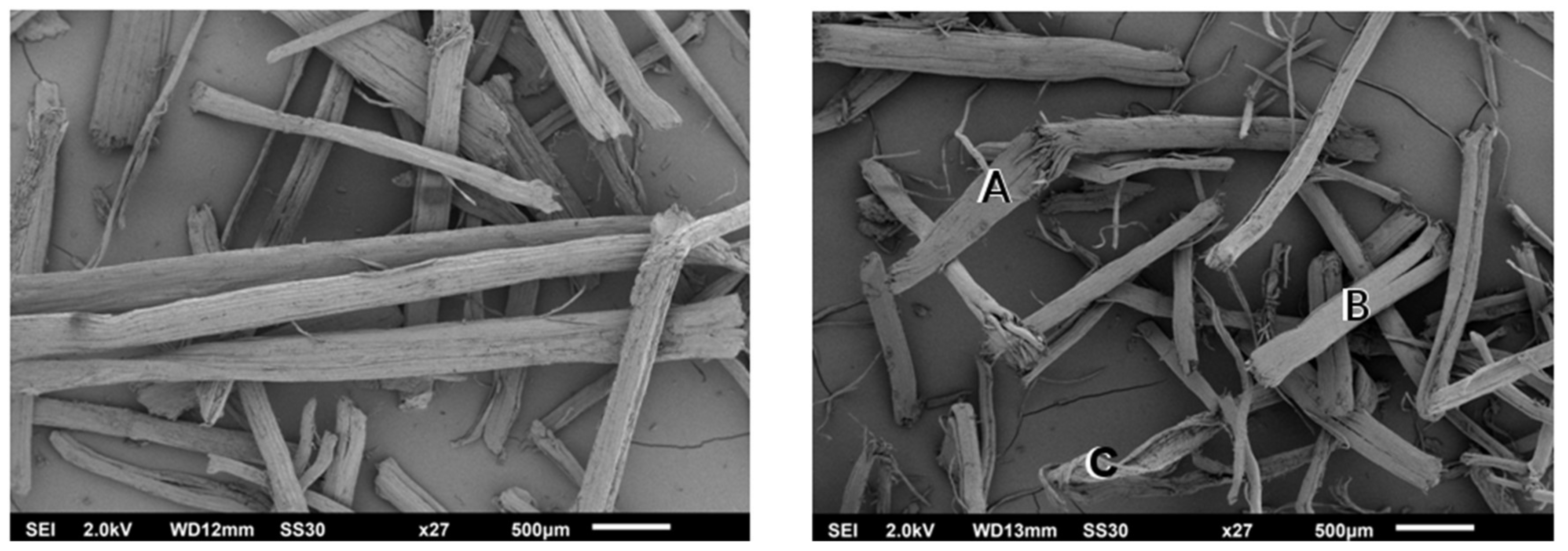
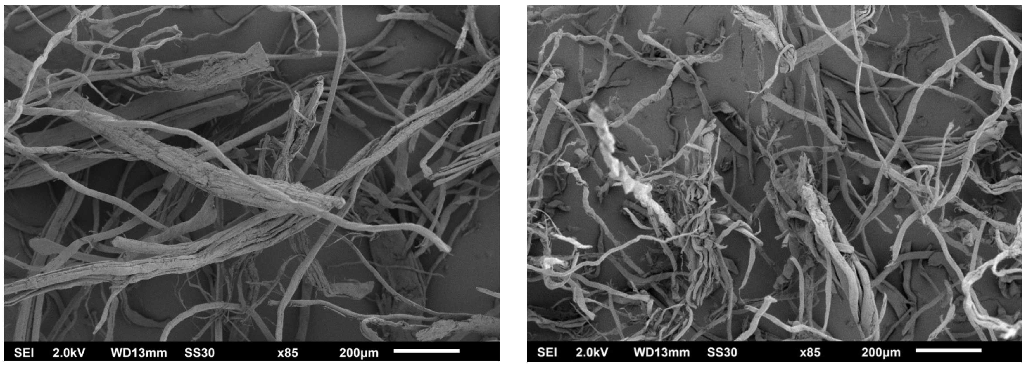
3.1. Optical Observations via SEM and Ultra-High-Speed Camera

The scanning electron microscopy (SEM) analysis showed a reduction of the length and width of sisal and flax (Figure 5 and Figure 6) during processing. In Figure 5 fibre breakage (A) and fibre splitting (B) was observed for sisal after compounding. In Figure 6 shorter and smaller fibre bundles can be observed after compounding for flax (right) compared to the original flax (left).
Flax fibre bundles show a fragile breaking behaviour, but elementary fibres break by fatigue [36]. The SEM analysis shows that, sisal has more cohesive bundles compared to flax. Castellani et al. [36] showed that, for sisal, the separation of bundles is difficult, before the separation they break into single fibres and chunks form. The elementary fibres often remain attached to the bundle surface of sisal [36]. Oksman et al. [53] also showed that flax is several times thinner compared to sisal after processing. This can also be seen on the SEM pictures in the present study (Figure 5 and Figure 6). Le Moigne et al. [54] and Oksman et al. [53] showed for flax fibre bundles during compounding a separation into single fibres, whereas sisal fibre bundles tend to separate in thinner bundles and, to a smaller amount, into single fibres.
The ultra-high-speed camera observation showed that the sisal fibre bundle failure starts with a peeling behaviour (Figure 7; 0.085 ms). This peeled part remains attached at one end to the sisal bundles and behaves like a whip. No further change can be observed for the next 10.095 ms. Then, the sisal fibre bundles starts to break and splits into smaller bundles at the breaking point until it is completely broken 0.070 ms later (Figure 7). In contrast, several very small bundles and single fibres start to split apart from the flax fibre bundle (Figure 8; 0.085 ms). Compared to sisal, in the next 10.095 ms more single fibres split apart. For the next 1.525 ms more single fibres split apart, until the flax fibre bundle is completely broken after 11.705 ms (Figure 8).
The ultra-high-speed camera analysis of the tensile tests encourages the breaking mechanisms of flax and sisal found by Castellani et al. [36]. From their compounding experiments they assume a peeling behaviour for sisal, while flax breaks brittle and splits into single fibres [36].

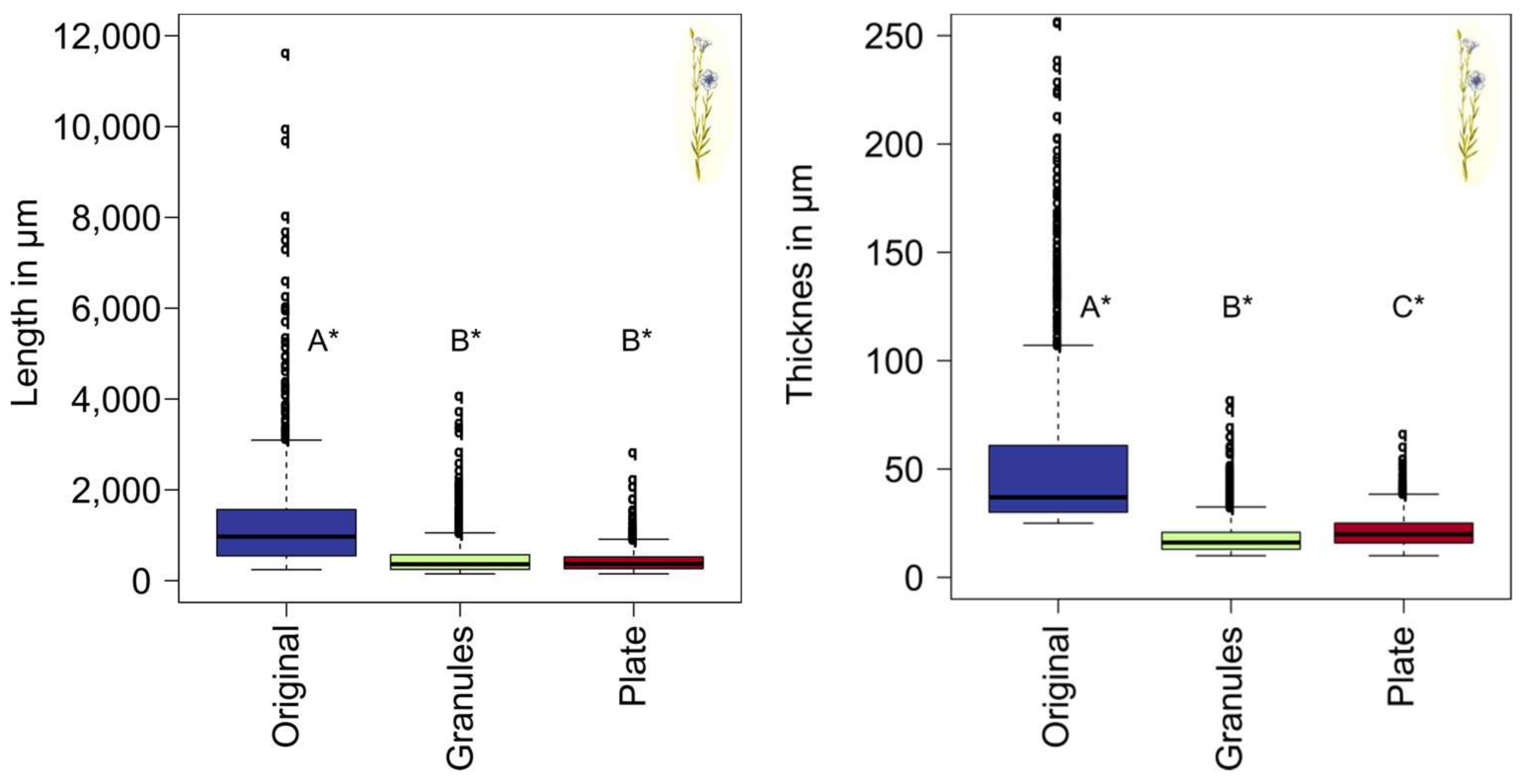
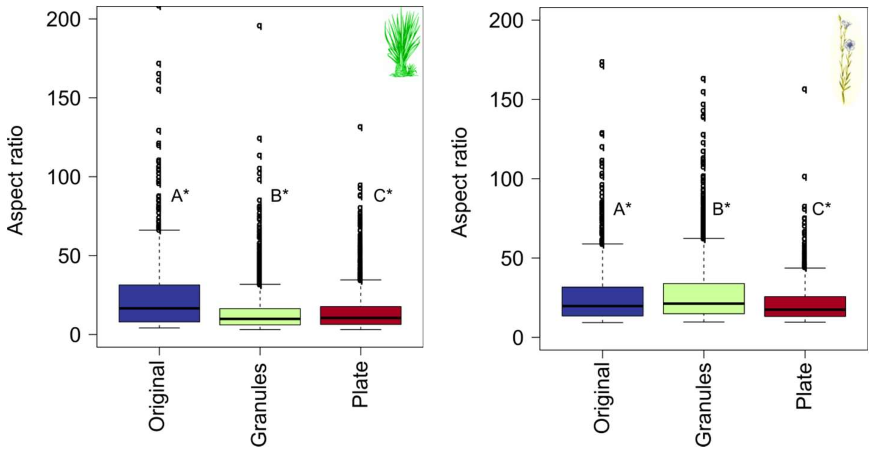
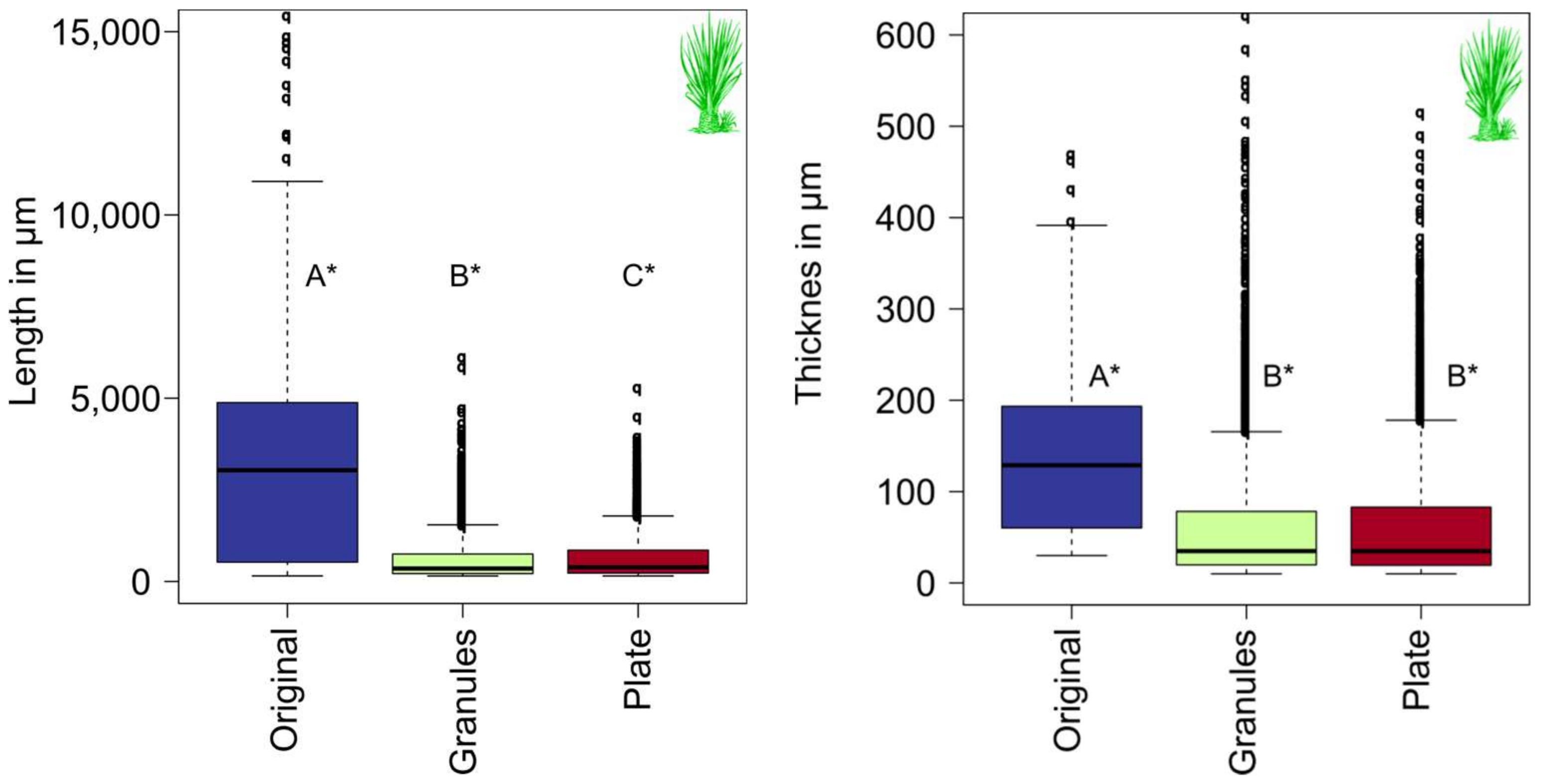
3.2. Morphological Analysis via FibreShape

Fibre length and aspect ratio influence the fibre rotation during injection moulding and, therefore, affect the fibre orientation and mechanical properties of the component. Consequently, it is important to analyse the fibre morphology experimentally, which may serve as input parameters for further simulation studies.
The distribution of the measured lengths and widths of sisal and flax is shown in Figure 9 and Figure 10, respectively. There is a significant change of the length and width of sisal and flax during compounding. The test of effect size also shows that there is a large effect of the compounding regarding the fibre morphology of sisal and flax. For sisal, a significant difference was found for fibre length before and after injection moulding (Figure 9 Left) and no significant difference regarding width (Figure 9 Right). However, the test of the size effect demonstrates that there is no effect on the length as a result of the injection moulding process. For the flax length, no significant influence of the injection moulding process could be found (Figure 10 Left), but a significant difference regarding the width (Figure 10 Right). For flax, the median of the width is even a bit higher after injection moulding compared to the objects in the granules. This does not mean that the fibre bundles were re-joined during the process, more likely being an artefact that different fibres can be measured before and after injection moulding as a result of having a new set of flax fibres with apparently thicker fibre bundles after injection moulding. Berzin et al. (2017) also found that each fibre bundle can split and/or break differently during the compounding process, according to its own dimensions [22].
To sum up, compounding has a large effect on fibre bundle breakage and fibre bundle splitting for sisal and flax. During injection moulding in our experiments, sisal and flax are not damaged further.
The aspect ratio is the ratio between the length of an object to the diameter (in our case the object width): L/D. If the fibres just break (reducing the length) during processing and do not split (maintaining the width), the aspect ratio decreases. This is valid for glass and carbon fibres. If the fibre bundles of natural fibres break and split, the aspect ratio does not necessarily need to decrease during processing. For sisal and flax a significantly change of the aspect ratio could be found during compounding and injection moulding. Regarding the effect size, compounding shows an intermediate effect and the injection moulding no effect on the aspect ratio of sisal. Compounding shows a large effect on the length and the width of sisal. It seems that sisal breaks more than it splits during compounding, therefore, the aspect ratio decreases. For flax, the compounding just shows a small effect on the aspect ratio, even though there is a significant difference in the results (Figure 11). Flax fibre bundles break and also split into smaller fibre bundles. The aspect ratio is almost the same before and after compounding for flax, with mean values of 26 and 28, respectively (Table 1).
For flax fibre bundles a separation into elementary fibres was found during processing, and sisal separates into thinner fibre bundles and just a few single fibres [53,54]. Literature values for the width for single flax fibres ranges from 1.7 to 76 µm and, for flax fibre bundles, from 40 to 620 µm (see [4] for a literature overview). In this study, the original flax has a mean thickness of 54 µm (Table 1) and is reduced to 18 µm during compounding. Already thin flax bundles were split into elementary fibres. Literature values for the width of single sisal fibres ranges from 4 to 47 µm and for sisal fibre bundles from 9 to 460 µm (see [4] for a literature overview). In this study, the original sisal has a mean thickness of 139 µm and is reduced during compounding to 68 µm (Table 1), which is still in the range of the fibre bundles.
Oksman et al. (2009) and Le Moigne et al. (2011) showed a strong reduction on the flax length, but a much higher aspect ratio for flax compared to sisal after compounding [53,54]. In the present study the aspect ratio of flax and sisal is almost the same before processing, at 26 ± 18 and 25 ± 28, respectively. After compounding, the aspect ratio for flax (28 ± 20) is twice as high for sisal (14 ± 12) (Table 1). In further studies regarding the length reduction of natural fibres, the fibres were analysed before compounding and after injection moulding, but not after compounding [55,56]. Thus, the length reduction of the two different processing steps cannot be distinguished. For the validation of the mechanistic model it is important to analyse the fibre length reduction after both process steps, as in our study.

3.3. Mechanistic Model

In Figure 12 the fibre breakage results of the mechanistic model are shown for flax and sisal. The fibre length reduction in percent is shown during injection moulding as a function of the length in the compound, before the injection moulding process. These values range from 0%, which means the fibre length has not changed during processing and is still the initial length, to theoretically 100% for fully broken fibres. The results show that sisal with an average length of 2 mm before injection moulding is reduced by 12.5% while entering the gate to an average length of 1.75 mm, whereas flax, with an average length of 2 mm, breaks to an average length of 0.8 mm, which is a reduction of almost 60% (Figure 12). In this study, the length of the fibres/fibre bundles were analysed in the compounds. Sisal has an average value of 647 µm and flax of 481 µm (Table 1). No further length reduction effect could be found during injection moulding for both fibre types. The mechanistic model showed the same results, the fibres do not break during injection moulding, if they are already reduced to 0.6 mm (sisal) and 0.5 mm (flax) during compounding.
The different fibre types vary in their breaking behaviour. Di Giuseppe et al. (2017) performed a study to analysis quantitatively the fibre breakage during compounding by an inner mixer for sisal, hemp, flax, and miscanthus [37]. They determined a “breakage index” for the length the diameter and the aspect ratio for all four fibre types. Sisal has the smallest breakage index, which means sisal breaks less under shear stress compared to the other fibre types. In contrast, flax shows the highest breakage index of all fibre types due to its fragile breaking behaviour [37]. Our simulation shows the same results, with the same original length, and flax has a much higher breakage index compared to sisal under shear stress.
The breakage behaviour is not only dependent on the fibre type, but also influenced by the original dimensions of the fibres; as expected the longer the fibre, higher breakage occurs [37]. This experimental observation can be confirmed with our results using the micromechanical model (Figure 12). The experimental analysis of the fibre length reduction during compounding shows a strong influence of the original fibre length. Sisal, with an original length of 3590 µm (mean), was reduced by 82% during compounding. Flax, with an original length of 1272 µm (mean,) was only reduced by 62% (Table 1), even though flax has a more fragile breaking behaviour. The breakage index is, therefore, not only dependent on the fibre type, but also on the original length.
The different breakage behaviour of the natural fibre does not only effect the length reduction but also the aspect ratio. In contrast to glass and carbon fibres, not only the length, but also the thickness, of natural fibre bundles can be changed while processing. As not only the length of sisal is reduced in the present study by 82%, but also the thickness decreases due to shear forces during compounding, the aspect ratio decreases by 44%. In contrast, the aspect ratio of flax even decreases slightly by 8%. Flax does not only break, but also splits into elementary fibres [36]. The additional splitting of the fibre bundles may have a positive effect on the mechanical properties of the compounds due to higher aspect ratio values, because not only the length, but also the aspect ratio, is affecting the reinforcement effect of natural fibres in the polymer [8,9].
In a further experimental study with a focus on achieving long fibres in the compound would be important to overachieve the critical fibre length in the injection moulding component. Therefore, for each natural fibre type the compounding process needs to be adapted. The micromechanical model can predict the necessary fibre length in the compounds to reach the necessary fibre length in the injection-moulded component. The micromechanical model can be used in this case as a product development tool to realize good mechanical properties in NFC.
Additionally, further studies with the mechanistic model, including the simulation of fibre bundle splitting, would be useful. Therefore, ambitious experimental analyses are necessary to determine the adhesion forces between the single fibres at the middle lamella. For first steps in this direction for flax were conducted by Charlet and Béakou (2011) [57]. The detachment forces at the middle lamella were analysed for two single flax fibres and a numerical modelling of the flax middle lamella was performed [57]. Including fibre splitting into the micromechanical model would be an important step to optimize the model as a product development tool for adequate prediction of mechanical properties in NFC due to exact determined fibre length and aspect ratio in the injection moulding component.
In addition to the prediction of the length reduction during injection moulding, the micromechanical model is primarily used to determine fibre interaction coefficients [47,48,49,55]. Fibre interaction coefficients are used in commercial simulation software programs (e.g., Moldex3D®, Cadmould®, MoldFlow®) to predict the fibre orientation during injection moulding. The fibre interaction coefficient is unique for each fibre-matrix combination. More information about the prediction of fibre interaction coefficients via micromechanical model is found in [50,51,52,58]. In the present study, the fibre interaction coefficients CI were analysed for 30 mass % fibres/PP for flax and sisal (Table 2). Further details can be found in [13,15,50]. CI is a phenomenological parameter for the fibre-fibre interaction, the higher the value, the higher the interaction between the fibres [10]. The CI value for sisal/PP is higher compared to flax/PP (Table 2). Sisal interacts more than the flax in the polymer melt; this is most probably because of the fibre/fibre bundle morphology. Sisal is longer and thicker compared to flax in the granules and in the injection moulded plates (Table 1).
The fibre interaction coefficient CI for sisal/PP was successfully used to determine the fibre orientation in an injection-moulding simulation using the software Cadmould® (Simcon Kunststofftechnische Software GmbH, Würselen, Germany). Details can be found in [13].
Further experimental studies with longer natural fibres are necessary to validate the fibre breakage prediction with the micromechanical model. Therefore, compounds with long fibres need to be produced, and different compounding process parameters need to be adapted, because high screw speeds and low feed rates increase the fibre fragmentation [59]. In addition to the breakage behaviour, it is important to analyse the possible fibre-matrix separation with long fibres in complex and thin-walled moulds. In the present project, a thin-walled mould of a glove box cover with fine ribs could be filled without separation between the short fibres and the matrix [15].

4. Conclusions

  • The length and width were significantly reduced during the compounding process for sisal and flax fibres. Statistically, a large effect of the compounding was found for length and width.
  • The injection moulding process showed neither any effect on a further length reduction nor further splitting for sisal and flax.
  • It is important to generate long fibres/fibre bundles already in the compound to overachieve the critical fibre length in the injection moulded component.
  • The micromechanical model can be used as a product development tool to predict the necessary object length in the granules to achieve the necessary object length in the injection moulded component to realize good mechanical properties.
  • If sisal and flax fall below a certain length during the compounding process, no further reduction of the fibre length can be observed during injection moulding. In the present study this phenomenon could be shown by experiments and simulations for a length of 500 µm (mean value) for flax and 600 µm (mean value) for sisal.
  • Splitting during processing is a very important fact for natural fibre bundles. The reduction of the fibre bundle width has a large influence on the aspect ratio (L/D). This phenomenon is not yet implemented in simulation. Before it can be implemented in the simulation, ambitious experiments are necessary to understand and measure the splitting of fibre bundles at the middle lamella.

Acknowledgments

The work was funded within the project “Material and Flow Models for Natural Fibre Reinforced Injection Moulding Materials for Practical Use in the Automotive Industry” by the German Federal Ministry of Food, Agriculture and Consumer Protection (BMEL) through the Fachagentur Nachwachsende Rohstoffe e.V. (FNR, Gülzow, Germany). Project partners were: Ford Forschungszentrum Aachen GmbH, Aachen, Germany; IAC (International Automotive Components), Ebersberg, Germany; LyondellBasell, Frankfurt, Germany; Kunststoffwerk Voerde Hueck and Schade GmbH and Co. KG, Ennepetal, Germany; Simcon Kunststofftechnische Software GmbH, Würselen, Germany; M-Base Engineering + Software GmbH, Aachen, Germany; University of Wisconsin-Madison, Madison, WI, USA; University of Applied Sciences and Arts Hannover, IfBB (Institute for Bioplastics and Biocomposites), Hannover, DE; HSB - City University of Applied Sciences Bremen, Bremen, Germany; Clausthal University of Technology, Institute of Polymer Materials and Plastic Engineering, Clausthal, Germany, and Fraunhofer LBF, Darmstadt, Germany. The authors would like to acknowledge Katharina Haag (The Biological Materials Group, City University of Applied Sciences Bremen, Bremen, Germany) for the help during high-speed recordings.

Author Contributions

Katharina Albrecht, Jörg Müssig, Erwin Baur, and Tim Osswald conceived and designed the experiments; Katharina Albrecht, Jörg Müssig, Thomas Meier, and Erwin Baur performed the experiments; Katharina Albrecht and Jörg Müssig analysed the data; Thomas Meier contributed the ultra-high-speed camera; the micromechanical model was developed for glass fibres and adapted to natural fibres by Tim Osswald and Erwin Baur; Katharina Albrecht wrote the first draft of the paper; Jörg Müssig and Tim Osswald revised the paper; Sandro Wartzack provided scientific support; and all authors contributed the final manuscript.

Conflicts of Interest

The authors declare no conflict of interest.

References

  1. Alkbir, M.F.M.; Sapuan, S.M.; Nuraini, A.A.; Ishak, M.R. Fibre properties and crashworthiness parameters of natural fibre-reinforced composite structure: A literature review. Compos. Struct. 2016, 148, 59–73. [Google Scholar] [CrossRef]
  2. Li, Y.; Mai, Y.-W.; Ye, L. Sisal fibre and its composites: A review of recent developments. Compos. Sci. Technol. 2000, 60, 2037–2055. [Google Scholar] [CrossRef]
  3. Mertens, O.; Gurr, J.; Krause, A. The utilization of thermomechanical pulp fibers in WPC: A review. J. Appl. Polym. Sci. 2017, 134, 45161. [Google Scholar] [CrossRef]
  4. Müssig, J.; Fischer, H.; Graupner, N.; Drieling, A. Testing Methods for Measuring Physical and Mechanical Fibre Properties (Plant and Animal Fibres). In Industrial Application Natural Fibres: Structures, Properties and Technical Applications; Müssig, J., Ed.; John Wiley & Sons, Ltd.: Hoboken, NJ, USA, 2010; pp. 267–309. [Google Scholar] [CrossRef]
  5. Pickering, K.L.; Efendy, M.G.A.; Le, T.M. A review of recent developments in natural fibre composites and their mechanical performance. Compos. Part A Appl. Sci. Manuf. 2016, 83, 98–112. [Google Scholar] [CrossRef] [Green Version]
  6. Shah, D.U. Natural fibre composites: Comprehensive ashby-type materials selection charts. Mater. Des. 2014, 62, 21–31. [Google Scholar] [CrossRef]
  7. Yan, L.; Chouw, N.; Jayaraman, K. Flax fibre and its composites—A review. Compos. Part B Eng. 2014, 56, 296–317. [Google Scholar] [CrossRef]
  8. Beaugrand, J.; Berzin, F. (2013): Lignocellulosic Fiber Reinforced Composites: Influence of Compounding Conditions on Defibrization and Mechanical Properties. J. Appl. Polym. Sci. 2013, 128, 1227–1238. [Google Scholar] [CrossRef]
  9. Graupner, N.; Albrecht, K.; Ziegmann, G.; Enzler, H.; Müssig, J. Influence of reprocessing on fibre length distribution, tensile strength and impact strength of injection moulded cellulose fibre-reinforced polylactide (PLA) composites. Express Polym. Lett. 2016, 10, 647–663. [Google Scholar] [CrossRef]
  10. Osswald, T.A.; Menges, G. Anisotropy Development during Processing. In Material Science Polymers Engineers, 3rd ed.; Osswald, T.A., Menges, G., Eds.; Hanser: Munich, Germany, 2012; pp. 263–294. [Google Scholar] [CrossRef]
  11. Rohde-Tibitanzl, M. State of the Art. In Direct Processing Long Fiber Reinforced Thermoplastic Composites Their Mechanical Behavior Static Dynamic Load; Carl Hanser Verlag GmbH & Co.: Munich, Germany, 2015; pp. 3–68. [Google Scholar] [CrossRef]
  12. Abdennadher, A. Injection Moulding of Natural Fibre Reinforced Polypropylene: Process, Microstructure and Properties. Ph.D. Thesis, Ecole Nationale Supérieure des Mines de Paris, Frankreich, Paris, France, 2015. [Google Scholar]
  13. Albrecht, K.; Baur, E.; Endres, H.-J.; Gente, R.; Graupner, N.; Koch, M.; Neudecker, M.; Osswald, T.; Schmidtke, P.; Wartzack, S.; et al. Measuring fibre orientation in sisal fibre-reinforced, injection moulded polypropylene-Pros and cons of the experimental methods to validate injection moulding simulation. Compos. Part A Appl. Sci. Manuf. 2017, 95, 54–64. [Google Scholar] [CrossRef]
  14. Azaman, M.D.; Sapuan, S.M.; Sulaiman, S.; Zainudin, E.S.; Abdan, K. An investigation of the processability of natural fibre reinforced polymer composites on shallow and flat thin-walled parts by injection moulding process. Mater. Des. 2013, 50, 451–456. [Google Scholar] [CrossRef] [Green Version]
  15. Ford Forschungszentrum Aachen GmbH, IAC Group GmbH, LyondellBasell, Kunststoffwerk Voerde, Simcon Kunststofftechnische Software GmbH, M-Base Engineering und Software GmbH, Hochschule Hannover, Hochschule Bremen, Technische Universität Clausthal, Fraunhofer LBF & University of Wisconsin-Madison. Werkstoff-und Fließmodelle für naturfaserverstärkte Spritzgießmaterialien für den praktischen Einsatz in der Automobilindustrie. Final Report of the Project “NFC-Simulation”. 2014. Available online: http://www.fnr-server.de/ftp/pdf/berichte/22005511.pdf (accessed on 23 March 2018). (In German).
  16. Nikklä, M.; Filz, P. Injection Moulding and Simulation of Consumer Products with Aqvacomp Composites. In Proceedings of the Biocomposites Conference Cologne (BCC)—7th Conference on Wood and Natural Fibre Composites, Maternushaus, Germany, 6–7 December 2017; nova-Institut GmbH: Maternushaus, Germany, 2017. [Google Scholar]
  17. Wan Abdul Rahman, W.A.; Sin, L.T.; Rahmat, A.R. Injection moulding simulation analysis of natural fiber composite window frame. J. Mater. Process. Technol. 2008, 197, 22–30. [Google Scholar] [CrossRef]
  18. Fu, S.-Y.; Lauke, B.; Mai, Y.-W. Science and Engineering of Short Fibre Reinforced Polymer Composites; Woodhead Publishing in Materials; Elsevier: Amsterdam, The Netherlands, 2009; ISBN 978-1-84569-269-8. [Google Scholar]
  19. Folgar, F.; Tucker, C.L. Orientation Behavior of Fibers in Concentrated Suspensions. J. Reinf. Plast. Compos. 1984, 3, 98–119. [Google Scholar] [CrossRef]
  20. Merodio, J.; Ogden, R.W. Instabilities and loss of ellipticity in fiber-reinforced compressible nonlinearly elastic solids under plane deformation. Int. J. Solids Struct. 2003, 40, 4707–4727. [Google Scholar] [CrossRef]
  21. Merodio, J.; Ogden, R.W. Material Instabilities for Fiber-Reinforced Nonlinearly Elastic solids under plane deformation. Arch. Mech. 2002, 54, 525–552. [Google Scholar]
  22. Berzin, F.; Beaugrand, J.; Dobosz, S.; Budtova, T.; Vergnes, B. Lignocellulosic fiber breakage in a molten polymer. Part 3. Modeling of the dimensional change of the fibers during compounding by twin screw extrusion. Compos. Part A Appl. Sci. Manuf. 2017, 101, 422–431. [Google Scholar] [CrossRef]
  23. Fu, S.-Y.; Hu, X.; Yue, C.-Y. Effects of fiber length and orientation distributions on the mechanical properties of short-fiber-reinforced polymers—A review. J. Soc. Mater. Sci. 1999, 48, 74–83. [Google Scholar] [CrossRef]
  24. Bajracharya, R.M.; Manalo, A.C.; Karunasena, W.; Lau, K.-T. Experimental and theoretical studies on the properties of injection moulded glass fibre reinforced mixed plastics composites. Compos. Part A Appl. Sci. Manuf. 2016, 84, 393–405. [Google Scholar] [CrossRef]
  25. Bijsterbosch, H.; Gaymans, R.J. Polyamide 6—Long glass fiber injection moldings. Polym. Compos. 1995, 16, 363–369. [Google Scholar] [CrossRef]
  26. Denault, J.; Vu-Khanh, T.; Foster, B. Tensile properties of injection molded long fiber thermoplastic composites. Polym. Compos. 1989, 10, 313–321. [Google Scholar] [CrossRef]
  27. Fu, S.-Y.; Lauke, B. Characterization of tensile behaviour of hybrid short glass fibre/calcite particle/ABS composites. Compos. Part A Appl. Sci. Manuf. 1998, 29, 575–583. [Google Scholar] [CrossRef]
  28. Fu, S.-Y.; Lauke, B. Fracture resistance of unfilled and calcite-particle-filled ABS composites reinforced by short glass fibers (SGF) under impact load. Compos. Part A Appl. Sci. Manuf. 1998, 29, 631–641. [Google Scholar] [CrossRef]
  29. Jaszkiewicz, A.; Meljon, A.; Bledzki, A.K.; Radwanski, M. Gaining knowledge on the processability of PLA-based short-fibre compounds—A comprehensive comparison with their PP counterparts. Compos. Part A Appl. Sci. Manuf. 2016, 83, 140–151. [Google Scholar] [CrossRef]
  30. Ramani, K.; Bank, D.; Kraemer, N. Effect of screw design on fiber damage in extrusion compounding and composite properties. Polym. Compos. 1995, 16, 258–266. [Google Scholar] [CrossRef]
  31. von Turkovich, R.; Erwin, L. Fiber fracture in reinforced thermoplastic processing. Polym. Eng. Sci. 1983, 23, 743–749. [Google Scholar] [CrossRef]
  32. Curtis, P.T.; Bader, M.G.; Bailey, J.E. The stiffness and strength of a polyamide thermoplastic reinforced with glass and carbon fibres. J. Mater. Sci. 1978, 13, 377–390. [Google Scholar] [CrossRef]
  33. Müssig, J.; Martens, R. Quality Aspects in Hemp Fibre Production—Influence of Cultivation, Harvesting and Retting. J. Ind. Hemp 2003, 8, 11–32. [Google Scholar] [CrossRef]
  34. Schnegelsberg, G. Handbuch der Faser–Theorie und Systematik der Faser; Deutscher Fachverlag: Frankfurt am Main, Germany, 1999; ISBN 978-3871506246. (In German) [Google Scholar]
  35. Vincent, J. A unified nomenclature for plant fibres for industrial use. Appl. Compos. Mater. 2000, 7, 269–271. [Google Scholar] [CrossRef]
  36. Castellani, R.; Di Giuseppe, E.; Beaugrand, J.; Dobosz, S.; Berzin, F.; Vergnes, B.; Budtova, T. Lignocellulosic fiber breakage in a molten polymer. Part 1. Qualitative analysis using rheo-optical observations. Compos. Part A Appl. Sci. Manuf. 2016, 91, 229–237. [Google Scholar] [CrossRef]
  37. Di Giuseppe, E.; Castellani, R.; Budtova, T.; Vergnes, B. Lignocellulosic fiber breakage in a molten polymer. Part 2. Quantitative analysis of the breakage mechanisms during compounding. Compos. Part A Appl. Sci. Manuf. 2017, 95, 31–39. [Google Scholar] [CrossRef]
  38. Baley, C. Influence of kink bands on the tensile strength of flax fibers. J. Mater. Sci. 2004, 39, 331–334. [Google Scholar] [CrossRef]
  39. Duc, A.L.; Vergnes, B.; Budtova, T. Polypropylene/natural fibres composites: Analysis of fibre dimensions after compounding and observations of fibre rupture by rheo-optics. Compos. Part A Appl. Sci. Manuf. 2011, 42, 1727–1737. [Google Scholar] [CrossRef]
  40. Hughes, M. Defects in natural fibres: Their origin, characteristics and implications for natural fibre-reinforced composites. J. Mater. Sci. 2012, 47, 599–609. [Google Scholar] [CrossRef]
  41. Bos, H.; Van Den Oever, M.; Peters, O. Tensile and compressive properties of flax fibres for natural fibre reinforced composites. J. Mater. Sci. 2002, 37, 1683–1692. [Google Scholar] [CrossRef]
  42. Hernandez-Estrada, A.; Gusovius, H.-J.; Müssig, J.; Highes, M. Assessing the Susceptibility of Hemp Fibre to the Formation of Dislocations during Processing. Ind. Crops Prod. 2016, 85, 382–388. [Google Scholar] [CrossRef]
  43. Steuernagel, L.; Ziegmann, G.; Meiners, D. Recycling of fiber reinforced thermoplastics—Natural fibers vs. glass fibers. In Proceedings of the CompositesWeek@Leuven and TexComp-11 Conference, Leuven, Belgium, 16–20 September 2013. [Google Scholar]
  44. Neudecker, M.; Endres, H.-J. Processing and Manufacturing of Natural Fiber Reinforced Plastics to Specimens for Generating Simulation Data (NFC-Simulation). In Proceedings of the ANTEC® 2014—Technical Conference & Exhibition, Las Vegas, NV, USA, 28–30 April 2014; Society of Plastics Engineers: Bethel, CT, USA, 2014; pp. 707–711, ISBN 978-0-9850112-4-6. [Google Scholar]
  45. Albrecht, K.; Osswald, T.; Wartzack, S.; Müssig, J. Natural fibre-reinforced, injection moulded polymers for light weight constructions—Simulation of sustainable materials for the automotive industry. In Proceedings of the 20th International Conference Engineering Design (ICED15), Politecnico di Milano, Italy, 27–30 July 2015; Volume 4, pp. 313–322, ISBN 978-1-904670-67-4. [Google Scholar]
  46. Cohan, J. Statistical Power Analysis for the Behavioral Sciences, 2nd ed.; Printed in the USA; Lawrence Erlbaum Associates: Lawrence, NJ, USA, 1988; ISBN 978-0-12-179060-8. [Google Scholar]
  47. Lenhard, W.; Lenhard, A. Calculation of Effect Sizes. Bibergau (Germany): Psychometrica. Available online: https://www.psychometrica.de/effect_size.html (accessed on 4 July 2017). [CrossRef]
  48. Bamberg, G.; Baur, F.; Krapp, M. Statistik. 14. Überarbeitete Auflage. Oldenbourgs Lehr-und Handbücher der Wirtschafts-u. Sozialwissenschaften; Oldenbourg Verlag: München, Germany, 2008; ISBN 978-3486272185. [Google Scholar]
  49. López, L.; Ramírez, D.; Osswald, T.A. Fiber Attrition and Orientation Productions of a Fiber Filled Polymer through a Gate—A Mechanistic Approach. In Proceedings of the ANTEC® 2013—Technical Conference & Exhibition, Cincinnati, OH, USA, 22–24 April 2013; Society of Plastics Engineers: Bethel, CT, USA, 2013; pp. 2163–2167, ISBN 978-1-63266-530-0. [Google Scholar]
  50. Baur, E.; Goris, S.; Ramírez, D.; Schmidtke, P.; Osswald, T. Mechanistic model to determine fiber orientation simulation material parameters. In Proceedings of the ANTEC® 2014—Technical Conference & Exhibition, Las Vegas, NV, USA, 28–30 April 2014; Society of Plastics Engineers: Bethel, CT, USA, 2014; pp. 1605–1610, ISBN 978-0-9850112-4-6. [Google Scholar]
  51. Ramírez, D. Study of Fiber Motion in Moding Processes by Means of a Mechanistic Model. Ph.D. Thesis, University of Wisconsin-Madison, Madison, WI, USA, 2014. [Google Scholar]
  52. Walter, I.; Goris, S.; Teuwsen, J.; Tapia, A.; Perez, C.; Osswald, T.A. A direct particle level simulation coupled with the Folgar-Tucker RSC Model to predict fiber orientation in injection molding of long glass fiber reinforced thermoplastics. In Proceedings of the ANTEC® 2017—Technical Conference & Exhibition, Anaheim, CA, USA, 8–10 May 2017; Society of Plastics Engineers: Bethel, CT, USA, 2017. ISBN 978-0-692-88309-9. [Google Scholar]
  53. Oksman, K.; Mathew, A.P.; Langström, R.; Nyström, B.; Joseph, K. The influence of fibre microstructure on fibre breakage and mechanical properties of natural fibre reinforced polypropylene. Compos. Sci. Technol. 2009, 69, 1847–1853. [Google Scholar] [CrossRef]
  54. Le Moigne, N.L.; van den Oever, M.; Budtova, T. A statistical analysis of fibre size and shape distribution after compounding in composites reinforced by natural fibres. Compos. Part A Appl. Sci. Manuf. 2011, 42, 1542–1550. [Google Scholar] [CrossRef]
  55. Hamma, A.; Kaci, M.; Ishak, Z.A.M.; Pegoretti, A. Starch-grafted-polypropylene/kenaf fibres composites. Part 1: Mechanical performances and viscoelastic behaviour. Compos. Part A Appl. Sci. Manuf. 2014, 56, 328–335. [Google Scholar] [CrossRef]
  56. Muthuraj, R.; Misra, M.; Defersha, F.; Mohanty, A.K. Influence of processing parameters on the impact strength of biocomposites: A statistical approach. Compos. Part A Appl. Sci. Manuf. 2016, 83, 120–129. [Google Scholar] [CrossRef]
  57. Charlet, K.; Béakou, A. Mechanical properties of interfaces within a flax bundle—Part I: Experimental analysis. Int. J. Adhes. Adhes. 2011, 31, 875–881. [Google Scholar] [CrossRef]
  58. Pérez, C.; Ramírez, D.; Osswald, T.A. Mechanistic model simulation of a compression molding process: Fiber orientation and fiber-matrix separation. In Proceedings of the ANTEC® 2015—Technical Conference & Exhibition, Orlando, FL, USA, 23–25 March 2015; Society of Plastics Engineers: Bethel, CT, USA, 2015. ISBN 9780985011277. [Google Scholar]
  59. Berzin, F.; Vergnes, B.; Beaugrand, J. Evolution of lignocellulosic fibre lengths along the screw profile during twin screw compounding with polycaprolactone. Compos. Part A Appl. Sci. Manuf. 2014, 59, 30–36. [Google Scholar] [CrossRef]
Figure 1. Fibre-matrix interaction, fibre damage mechanism at the interface between solid pellets and polymer melt [10].
Jcs 02 00020 g001
Figure 2. Different breakage mechanisms of natural fibres during compounding in a thermoplastic polymer melt. The numbers in black indicate Klason lignin content and, in grey, hemicellulose mass% content [36].
Jcs 02 00020 g002
Figure 3. Discretization of a fibre as a chain of elements, corresponding forces, and momentum balance for an individual element [50].
Jcs 02 00020 g003
Figure 4. Fibre-fibre interaction and further effects which are included in the mechanistic model [50].
Jcs 02 00020 g004
Figure 5. SEM pictures of sisal fibre bundles before (left) und after compounding (right). A: Fibre bundle breakage. B: Start of fibre bundle splitting. C: Peeling behaviour of sisal.
Jcs 02 00020 g005
Figure 6. SEM pictures of flax fibre bundles before (left) und after compounding (right).
Jcs 02 00020 g006
Figure 7. Ultra-high-speed camera observation during tensile tests of sisal fibre bundles. *: 0 ms presents the last picture without any visible fibre failure.
Jcs 02 00020 g007
Figure 8. Ultra-high-speed camera observation during tensile tests of flax fibre bundles. *: 0 ms presents the last picture without any visible fibre failure.
Jcs 02 00020 g008
Figure 9. Distribution of the length (left) and width (right) for sisal before processing (original), after compounding (granules), and after injection moulding (plate). The results are shown as box-and-whisker plots (whiskers with a maximum of 1.5 × IQR, outliers shown as circles). Boxplots with * represent not normally distributed samples and different capitals represent significant differences.
Jcs 02 00020 g009
Figure 10. Distribution of the length (left) and width (right) for flax before processing (original), after compounding (granules), and after injection moulding (plate). The results are shown as box-and-whisker plots (whiskers with a maximum of 1.5 × IQR, outliers shown as circles). Boxplots with * represent not normally distributed samples and different capitals represent significant differences.
Jcs 02 00020 g010
Figure 11. Change of the aspect ratio for sisal (left) and flax (right): before processing (original), after compounding (granules), and after injection moulding (plate). The results are shown as box-and-whisker plots (whiskers with a maximum of 1.5 × IQR, outliers shown as circles). Boxplots with * represent not normally distributed samples and different capitals represent significant differences.
Jcs 02 00020 g011
Figure 12. Fibre breakage results of the mechanistic model for flax and sisal. The x-axis shows the average fibre length before the injection moulding process, before entering the gate. The y-axis shows the percentage of the length reduction as the fibres enter the mould after the gate during injection moulding.
Jcs 02 00020 g012
Table 1. Mean, standard deviation (SD), and median of the measured fibre length thickness and aspect ratio for flax and sisal. The analysis was done with FibreShape; n is the number of counted objects.
FlaxOriginalGranulesPlate
n111021791275
Mean ± SDMedianMean ± SDMedianMean ± SDMedian
Length in µm1272 ± 1137970481 ± 376362438 ± 257369
Thickness in µm54 ± 413718 ± 81621 ± 820
Aspect ratio26 ± 182028 ± 202121 ± 1318
SisalOriginalGranulesPlate
n70924362468
Mean ± SDMedianMean ± SDMedianMean ± SDMedian
Length in µm3590 ± 40263034647 ± 702353666 ± 660388
Thickness in µm139 ± 8812969 ± 823568 ± 7535
Aspect ratio25 ± 281714 ± 121014 ± 1211
Table 2. Fibre interaction coefficients CI for flax and sisal PP.
PP-Compound (30 Mass % of Fibres)CI
Flax0.0037
Sisal0.0059

