Micromechanical Analysis for Two-Phase Copper-Silver Composites under Large Deformations

School of Mechanical Engineering, Faculty of Engineering, Tel Aviv University, 69978 Ramat Aviv, Israel
J. Compos. Sci. 2018, 2(1), 1; https://doi.org/10.3390/jcs2010001
Submission received: 29 October 2017
/
Revised: 12 December 2017
/
Accepted: 18 December 2017
/
Published: 21 December 2017
Abstract
:This study presents a homogenization based on micromechanics approach for a two-phase copper (Cu)-silver (Ag) composite undergoing finite deformations. In this approach, the high-fidelity generalized method of cells (HFGMC) is implemented for the prediction of the effective behavior of two cold-drawn Cu-Ag composites with different drawing strains and to obtain the field (deformation gradient and stress) distributions in the composite. Both metals (Cu or Ag) are rate-dependent crystal plasticity material constituents. HFGMC is applied for studying the deformation behavior of two-phase Cu-Ag composites under uniaxial compression. The micromechanical approach has been verified by comparison with experimental and finite element simulation results. Results in terms of deformation behavior and field distributions are given for two different cold-drawn composites.
1. Introduction
In the last few decades, nonlinear micromechanical models of multiphase composite materials have been the subject of interest for many investigations. The aim of these models is to study the effect of volume fraction and the interphase effects on generating the nonlinear effective response of the composite materials. A detailed review of this class of nonlinear micromechanical methods can be found in [1,2,3], among several others. In addition, the prediction of the local deformation process of periodic alternate multiphase materials requires the detailed description of the spacial description of the soft and hard phases subject to different kinds of loading [4]. Hence, the formation of constitutive equations that govern the large deformations of composite materials, which consist of elasto-viscoplastic phases, is necessary for the modeling and analysis of their deformation behavior. Eutectic Cu-Ag composites form an example of a layered two-phase composite structure that consists of alternate layers of Cu and Ag lamellae inside the grains.
Semi-analytical homogenization such as a generalized method of cells (GMC) has been developed by [1]. This method enables the modeling of complex unit-cell morphologies and is able to study the mechanical response of heterogeneous materials. The generalized method of cells (GMC) is used to predict the thermoelastic behavior of multiphase composites by including the thermal tangent tensor in the constitutive law. The effective tangent and thermal tensors are functions of the mechanical and thermal concentration tensor, respectively. The concentration tensor indicates the relationships between the local and overall behavior. Aboudi [3] also proposed an expanded form of the micromechanical approach to predict the hyperelastic response of viscoelastic multiphase composites. This approach uses viscoelastic, as well as mechanical concentration tensors to form relationships between the local and effective deformation. Moghaddam et al. [5] apply the GMC for determining the elastoplastic behavior by employing the single-crystal plasticity constitutive model. Aboudi proposes a method that can predict the viscoplastic, as well as thermoelastic behavior of multiphase composites. The proposed high fidelity generalized method of cells (HFGMC) includes second order displacement expansion in the multi-cell configuration of the repeating unit-cell (RUC). The HFGMC has been developed in order to predict the local distribution of stresses and strains in a refined manner that previously could not be generated by the GMC [6].
Numerical micromechanical models for two-phase repeating unit-cell (RUC) can be achieved using phenomenological material models at lower length scales, such as finite element, viscoplastic self-consistent and Taylor models [5,7,8]. Another alternative model directly specified for periodic composites is the high fidelity generalized method of cells (HFGMC). HFGMC can be considered as a higher order extension of the generalized method of cells (GMC) [6]. In the HFGMC approach for two-phase composites, the RUC consists of different numbers of subcells. In this approach, the higher order displacement expansion is used in the subcells, utilizing both displacement and stress microvariables to satisfy on an average basis, the equilibrium and continuity (traction and displacement) equations and periodic conditions across the interface between the cells. In Aboudi et al. [3], the HFGMC computational approach has been applied to predict the deformation behavior of various types of multiphase composite materials (elastic, viscoelastic, thermoviscoelastic and electroelastic). In the current work, the HFGMC was enhanced to include crystal plasticity material modeling for two-phase copper-silver composites.
This study presents general formulations for the HFGMC modeling framework implemented with the crystal plasticity material model for two-phase Cu-Ag composites undergoing large deformations. The behavior of composites with elasto-viscoplastic material constituents undergoing large deformations is allowed to deviate far away from equilibrium and is modeled by the HFGMC micromechanical theory. For a given constitutive model, both the micromechanical and macromechanical governing equations based on the homogenization technique for periodic composites are developed, wherein the instantaneous mechanical concentration tensors that relate the local induced deformation in the phase to the current externally-applied deformation gradient are given. Furthermore, the macroscopic constitutive equations of the two-phase composite in terms of its instantaneous stiffness tensors are also provided.
The structure of this paper is outlined as follows. Section 2 deals with the experimental observations for both samples. Section 3 introduces the constitutive equations of a finite elasto-viscoplastic material model based on the isomorphy concept of the elastic laws [9]. Section 4 describes the computational methodology for HFGMC formulation. Section 5 presents results in terms of mechanical behavior, and finally, conclusions are given in Section 6.
Notation: We use the symbolic notation given in the continuum mechanics text book of Bertram [9]. Scalars, vectors, second-order and fourth-order tensors are denoted by a, , and , respectively. The scalar, dyadic and Rayleigh product are given by ·, ⊗ and , respectively, where , , . : denotes the double contraction between tensors, i.e., . , and denote the transpose, the inverse and the material time derivative of a second-order tensor . The linear mapping of a second-order tensor by a fourth-order tensor is written as .
2. Experimental Methodology
The two cold-drawn Cu-Ag rods having diameters of 12.42 mm () and 6.73 mm () are produced by die casting. The volume fraction of each phase in the polycrystals is given as , . Both samples (, ) exhibit a crystallographic texture with different strengths, respectively. X-ray analysis is used to determine the bulk texture of two different cold-drawn Cu-Ag rods. X-ray diffraction (XRD) measurements are performed by using an X-ray tube with a chromium-anode in point focus mode and a 1D detector with secondary filtering. The measured texture from both samples (, ) has been approximated by 100 grains as a compromise between the precision and computational costs. More details about the initial texture and approximated texture (100 grains) are given in [10,11]. The compression tests are carried out for both cylindrical samples on a universal testing machine. These tests are operated at room temperature for a constant strain rate of s. The results are reported in terms of true stress () and compressive strain ().
3. Constitutive Equations
3.1. Elastic Law
In the present investigation, an elasto-viscoplastic single-crystal constitutive model [9] is considered for the lamellar structure of the Cu and Ag phases. An elasto-viscoplastic material model is applied on the microscale to investigate the material behavior of the aforementioned Cu-Ag polycrystals. Following Lee [12], the deformation gradient is multiplicatively decomposed into an elastic part and a plastic part :
where is the elastic part of the deformation gradient describing elastic stretch and rigid rotation and indicates the plastic contribution from crystallographic slips. The deformation gradient with respect to undistorted state can be defined by:
From Equation (2), it can be seen that and correspond to the elastic part and the inverse of the plastic part of the deformation gradient.
For a prescribed macro deformation in terms of Green’s strain tensor , the second Piola–Kirchhoff stress tensor is given by an anisotropic St.Venant–Kirchhoff law:
with:
In Equation (4), denotes Green’s strain tensor with respect to the undistorted placement. denotes the fourth-order constant stiffness tetrad for a cubic crystal. The tilde indicates that the is formulated with respect to the undistorted placement. The stiffness tetrad is represented by a six by six Voigt matrix, and the components refer to the normalized orthonormal basis of symmetric second-order tensors [13,14,15], i.e., :
Copper and silver constituents have a face-centered cubic (fcc) crystal structure. The three independent elastic constants for copper are GPa, GPa and GPa and for silver GPa, GPa and GPa.
3.2. Flow Rule
In general, fcc materials exhibit crystallographic slip in slip systems. These 12 primary slip systems are described by the Schmid tensors , which are given by the slip direction and the slip plane normal . The resolved shear stress in a slip system can be calculated as:
An evolution of the plastic part of is given in terms of the shear rate and the Schmid tensors :
The kinetics of dislocation motion have been elaborated by the relationships between the resolved shear stress and the plastic shear rate of the slip system by using the power law [16]:
where is a constant reference shear rate, and the exponent m determines the strain sensitivity of the material. The initial conditions of the evolution Equation (11) are . The orientation of the crystal is given by a proper orthogonal tensor . Here, is the orthonormal vector base of a fixed Cartesian coordinate system, and is the orthonormal lattice vector base. The initial resolved shear stress at time is given as .
3.3. Hardening Rule
A simple and very popular ansatz for the two types of hardening (self and latent) is the linear hardening rule [9,17].
where and are the matrix components, which account for self- and latent hardening of the crystal. For the fcc cubic crystal having 12 primary slip systems, we consider equal to 1.0 for the coplanar slip systems and equal to 0.9 for non-coplanar systems. The critical resolved shear stress of all slip systems as a function of shear is described by a Voce-type hardening law: [18]
with:
is given as an integral over the sum of shear rates of all slip systems. The Voce-type hardening rule contains four hardening parameters, namely the initial resolved shear stress , a saturation stress , an initial hardening modulus and a remaining hardening modulus . The material model has been implemented in the subroutine, in conjunction with HFGMC for homogenization. A Newton–Raphson iteration has been performed using a backward Euler scheme [19].
Since the micromechanical analysis uses the actual stresses, let us apply the following relation that provides the first Piola–Kirchhoff stress tensor in terms of the second Piola–Kirchhoff stress tensor :
Consequently, the following incremental constitutive law of the elasto-viscoplastic material is obtained:
where is the fourth-order tangent tensor of the material given by:
The incremental constitutive Equation (17) of the elasto-viscoplastic material will be used in the micromechanical analysis described in the following to determine the macroscopic finite deformation behavior of two-phase composites composed of Cu/Ag constituents.
4. Computational Methodology
The HFGMC micromechanical modeling theoretical framework with periodic microstructure is shown in Figure 1. The composite with a periodic microstructure is shown in Figure 1a with respect to the initial global coordinates (, , ). The repeating unit-cell (RUC) geometry of a two-phase periodic composite is divided into an orthogonal number of subcells, defined with respect to initial local coordinates (, , ) (see Figure 1b). The RUC of the two-phase composite is separated into , and subcells in the , and directions, respectively. Each subcell contains a different homogeneous elasto-viscoplastic material. The dimensions of subcell () along the 1, 2 and 3 axes are denoted by , and , respectively. In each subcell, a local coordinate system (, , ) is introduced, and the origin is located at the center of the subcell (see Figure 1c).
In the framework of HFGMC micromechanical formulation, the increment of the displacement vector is expanded to second-order as follows:
where consists of the externally-applied mechanical loading, and the unknown coefficients are determined, as shown in the following, by implementing the constitutive relations, equilibrium equations together with the interfacial and periodic conditions in the average (integral) sense.
The increments of the components of the deformation gradient tensor are:
After lengthy manipulations [3] in which the equilibrium equations in the subcell, interfacial conditions between the subcells and periodicity conditions are imposed in the average sense, the following equation is obtained:
where is a fourth-order concentration tensor, which relates the local increment of the deformation gradient in the subcell to the externally-applied one . Consequently, once the increment of the deformation gradient in the subcell has been established, the increment of the first Piola–Kirchhoff stress () in the subcell can be readily determined. Thus, Equation (17) can be rewritten as follows:
where is the fourth-order tensor of the material within subcell .
In the numerical implementation of HFGMC, the analytical derivation of the HFGMC model [20] is implemented and coupled with the crystal plasticity material model for two-phase Cu-Ag composites. Each subcell contains either Cu or Ag material constituents. Each subcell in the RUC is labeled by the indices () with , and . The material parameters for both samples (, ) are listed in Table 1 [11]. The repeating unit-cell (RUC) is subject to uniaxial compression for two different textured Cu-Ag samples (, ) to study the deformation behavior.
5. Numerical Results
In order to illustrate an application of these constitutive equations, we consider two different textured samples (, ) whose material properties are given in Table 1. Figure 2A,B illustrates the uniaxial mechanical response calibrated from the proposed elasto-viscoplastic HFGMC model compared to the experimental and finite element simulation results under isothermal conditions.
In Figure 2A, the Cauchy stress variations with are caused by the application of uniaxial compression in the Z direction of the large Cu-Ag sample . In addition comparisons between the true stresses based on the experimental investigations and finite element simulations [11] of the two-phase Cu-Ag sample are shown. The slight difference in the yield stress predicted by the HFGMC method may be attributed to the fact that in the HFGMC model, the constitutive equations and boundary conditions are implemented in a point-wise manner and in the average sense, respectively. The correspondence of the HFGMC plot to the experimental data and finite element simulated curve is reasonable.
In Figure 2B, the composite mechanical response to uniaxial compression loading of the two-phase Cu-Ag sample is shown by the macroscopic mechanical response ( vs. ). Besides, the comparisons between the experimental and finite simulation results [11] are shown. The HFGMC deformation behavior is in reasonable agreement with the experimental and finite element-simulated curve. However, there is a slight difference in the yield stress and strain hardening in the HFGMC approach. The difference may be due to the heterogeneity in the microstructure and the identified material parameters for sample . In addition, the governing equations and boundary conditions are enforced in a point-wise manner and in the average sense, respectively. As seen in Figure 2A,B, the mechanical response are identical in the elastic and elastoplastic region. It can be seen that there is a smooth transition from the elastic to elastoplastic region. The mechanical response however coincides with the corresponding experimental and finite element simulated results. Here, the nonlinearity of the elasto-viscoplastic material is well observed.
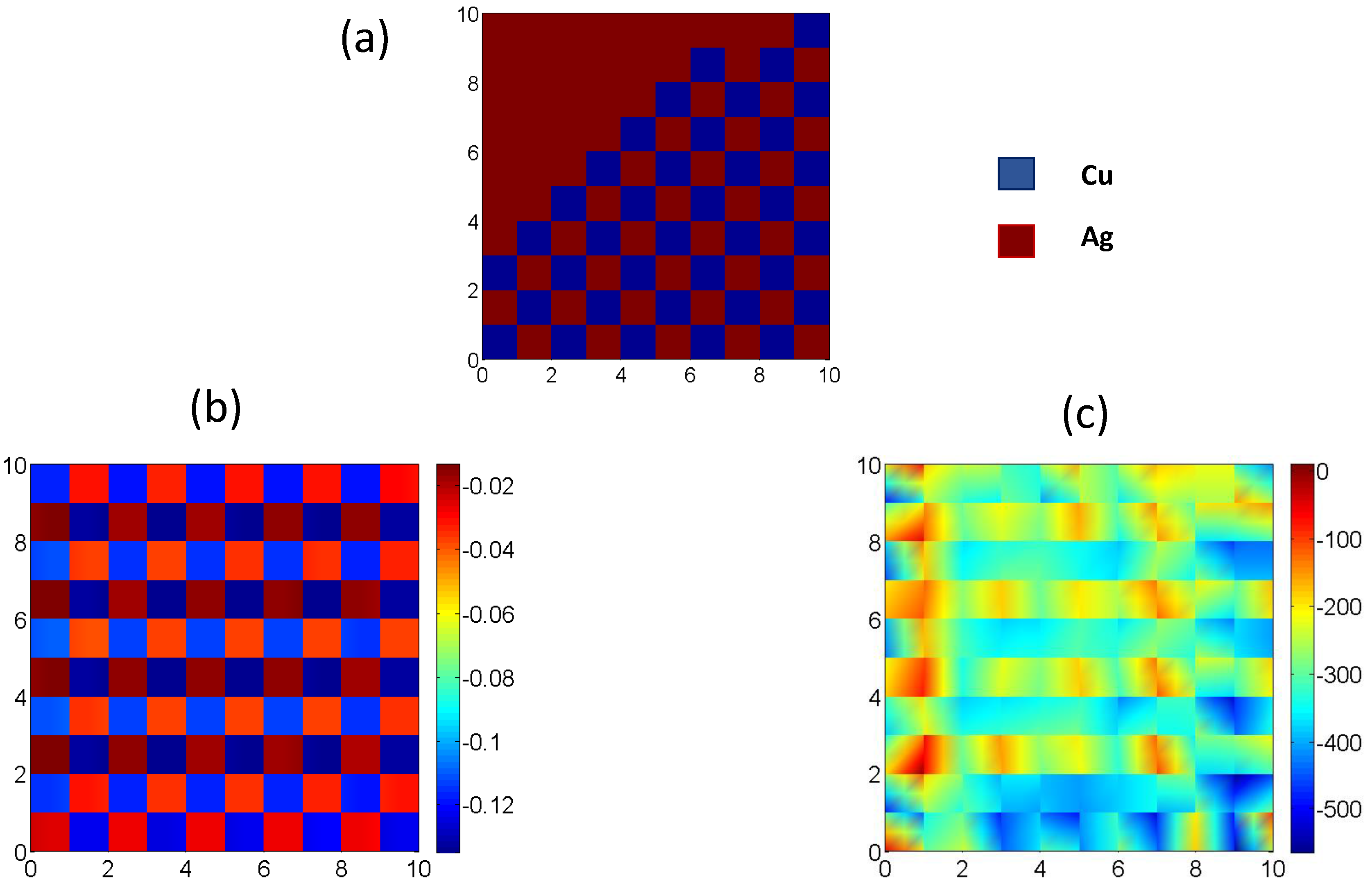
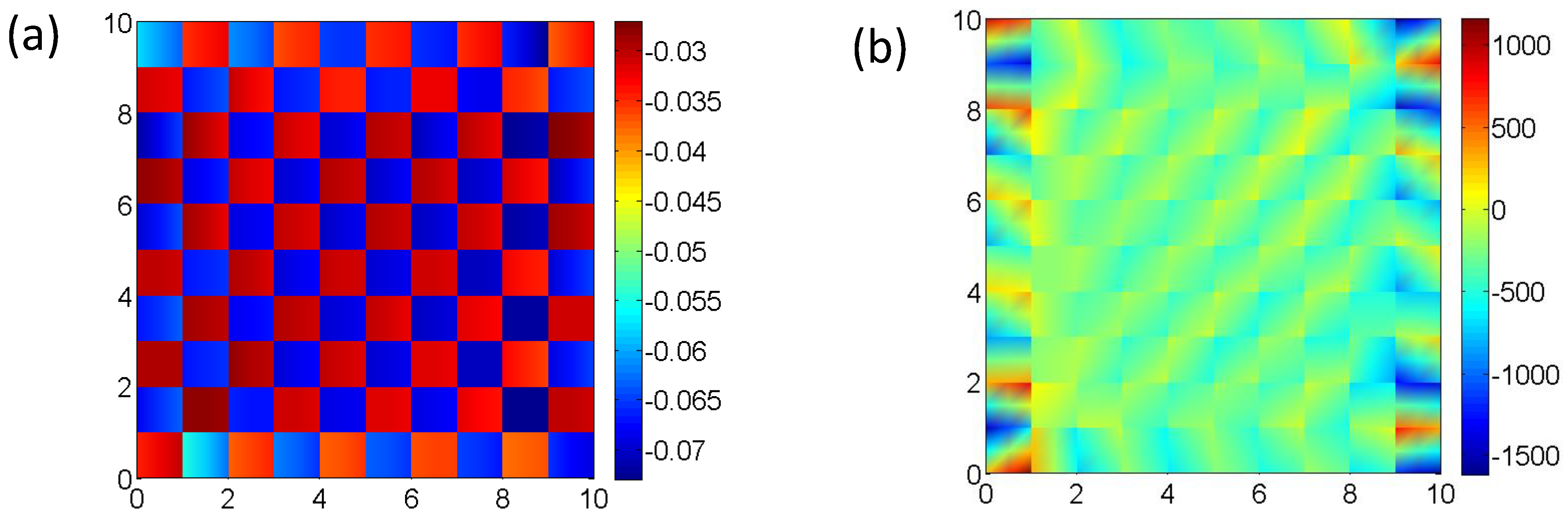
The distribution of the constituents (Cu/Ag), deformation gradient and the first Piola–Kirchhoff stress for sample is examined in Figure 3. Figure 3a shows the distribution of the material in the plane - at , i.e., on the examined cross-section. Here, Cu and Ag constituents with different color contours are shown in the figure (see Figure 3a). Figure 3b,c shows the axial deformation gradient and the first Piola–Kirchhoff stress , respectively. The results show that all subcells are under compression , and the stresses are distributed accordingly for the hard (Cu) and soft (Ag) phase, respectively. The distribution of the and for the sample in the plane - at , i.e., , is demonstrated in Figure 4. It can be clearly observed that subcells are under compression (see Figure 4a). The stress distribution shown in Figure 4b presents that the HFGMC homogenization under a crystal plasticity material modeling predicts the expected distribution at the macroscale.
6. Conclusions
A new elasto-viscoplastic micromechanical formulation for the HFGMC is proposed using elasto-viscoplastic material for Cu and Ag constituents. A HFGMC micromechanical model is employed for the prediction of the mechanical response of two-phase Cu-Ag composites for two different samples (, ) in which each constituent (Cu or Ag) is considered as a rate-dependent elasto-viscoplastic material. The reliability of the micromechanical model prediction is investigated by comparison with the experimental results and finite element simulations, which is valid under a uniaxial compression loading. The stress-strain results for both samples under uniaxial compression show that the effect of plastic deformation behavior is significant.
This HFGMC homogenization model has the advantage of modeling a two-phase periodic composite by discretizing the RUC into quite a few subcells. For example, in the present investigation, 10 × 10 × 10 subcells are sufficient to provide good accuracy. Besides, the running time of the program is quite short (several minutes). In addition, due to the rectangular shape of the subcells, the discretization of the repeating unit-cell is quite simple.
The proposed HFGMC model is shown to be effective for two different Cu-Ag composites calibrated using available experimental data and finite element simulation results. The results of the deformation behavior of the two-phase composites from the proposed HFGMC show the applicability of the proposed model to the wide range of crystalline materials, as well as the multiphase composites.
Acknowledgments
I would like to thank Jacob Aboudi and Rami Haj-Ali (Tel Aviv University, Israel) for fruitful discussions.
Conflicts of Interest
The author declares no conflict of interest.
References
- Aboudi, J. Mechanics of Composite Materials: A Unified Micromechanical Approach; Elsvier: Amsterdam, The Netherlands, 1991. [Google Scholar]
- Nemat-Nasser, S.; Horii, M. Overall Properties of Heterogeneous Materials; North Holland Publishing Co.: Amsterdam, NY, USA, 1993. [Google Scholar]
- Aboudi, J.; Arnold, S.M.; Bednarcyk, B.A. Micromechanics of Composite Materials: A Generalised Mutiscale Analysis Approach; Elsvier: Oxford, UK, 2013. [Google Scholar]
- Haj-Ali, R.; Aboudi, J. Nonlinear micromechanical formulation of the high fidelity generalized method of cells. Int. J. Solids Struct. 2009, 46, 2577–2592. [Google Scholar] [CrossRef]
- Moghaddam, M.G.; Achuthan, A.; Bednarcyk, B.A.; Arnold, S.M.; Pineda, E.J. A Multiscale Computational Model Combining a Single Crystal Plasticity Constitutive Model with the Generalized Method of Cells (GMC) for Metallic Polycrystals. Materials 2016, 9, 335. [Google Scholar] [CrossRef] [PubMed]
- Aboudi, J. The Generalized Method of Cells and High-Fidelity Generalized Method of Cells Micromechanical Models—A Review. Mech. Adv. Mater. Struct. 2004, 11, 329–366. [Google Scholar] [CrossRef]
- Commentz, B.; Hartig, C.; Mecking, H. Micromechanical interaction in two-phase iron-copper polycrystals. Comput. Mater. Sci. 1999, 16, 237–247. [Google Scholar] [CrossRef]
- Hoffmann, T.; Bertram, A.; Shim, S.; Tischler, J.Z.; Larson, B.C. Experimental Identification and Validation of a Crystal Plasticity Model for a Low Carbon Steel on Different Length Scales. Int. J. Mater. Form. 2010, 3, 65–68. [Google Scholar] [CrossRef]
- Bertram, A. Elasticity and Plasticity of Large Deformations—An Introduction, 3rd ed.; Springer: Berlin, Germany, 2012. [Google Scholar]
- Dodla, S.; Thiem, P.; Krüger, M.; Dietrich, D.; Bertram, A. Microstructure, flow behavior, and bulk texture evolution of cold drawn copper-silver composites. J. Alloys Compd. 2015, 647, 519–527. [Google Scholar] [CrossRef] [Green Version]
- Dodla, S.; Bertram, A.; Krüger, M. Finite element simulation of lamellar copper-silver composites. Comput. Mater. Sci. 2015, 101, 29–38. [Google Scholar] [CrossRef] [Green Version]
- Lee, E.H. Elastic-plastic deformation at finite strains. J. Appl. Mech. 1969, 36, 1–6. [Google Scholar] [CrossRef]
- Böhlke, T.; Bertram, A. The evolution of Hooke’s law due to texture development in FCC polycrystals. Int. J. Solids Struct. 2001, 38, 9437–9459. [Google Scholar] [CrossRef]
- Cowin, S. Properties of the anisotropic elasticity tensor. Q. J. Mech. Appl. Math. 1989, 42, 249–266. [Google Scholar] [CrossRef]
- Böhlke, T. Crystallographic Texture Evolution and Elastic Anisotropy: Simulation, Modeling and Applications; Shaker Verlag: Aachen, Germany, 2001. [Google Scholar]
- Hutchinson, J. Bounds and self-consistent estimates for creep of polycrystalline materials. Proc. R. Soc. Lond. A 1976, 348, 101–127. [Google Scholar] [CrossRef]
- Hill, R. Generalized constitutive relations for incremental deformation of metal crystals by multislip. J. Mech. Phys. Solids 1966, 14, 95–102. [Google Scholar] [CrossRef]
- Voce, E. A practial strain-hardening function. Metallurgia 1955, 51, 219–226. [Google Scholar]
- Böhlke, T.; Risy, G.; Bertram, A. Finite element simulation of metal forming operations with texture based material models. Model. Simul. Mater. Sci. Eng. 2006, 14, 365–387. [Google Scholar] [CrossRef]
- Aboudi, J.; Volokh, K.Y. Failure Prediction of Unidirectional Composites Undergoing Large Deformations. J. Appl. Mech. 2015, 82, 071004. [Google Scholar] [CrossRef]
Figure 1.
Schematic illustration of a two-phase composite. (a) Cu-Ag composite containing multiple repeating unit-cells (RUCs), defined with respect to global coordinates (, ); (b) the repeating unit-cell (RUC), defined in the local coordinates (, , ); it is separated into subcells, in the , and directions, respectively; and (c) a characteristic subcell (), defined within a local coordinate system (, , ) whose origin is located at the center.
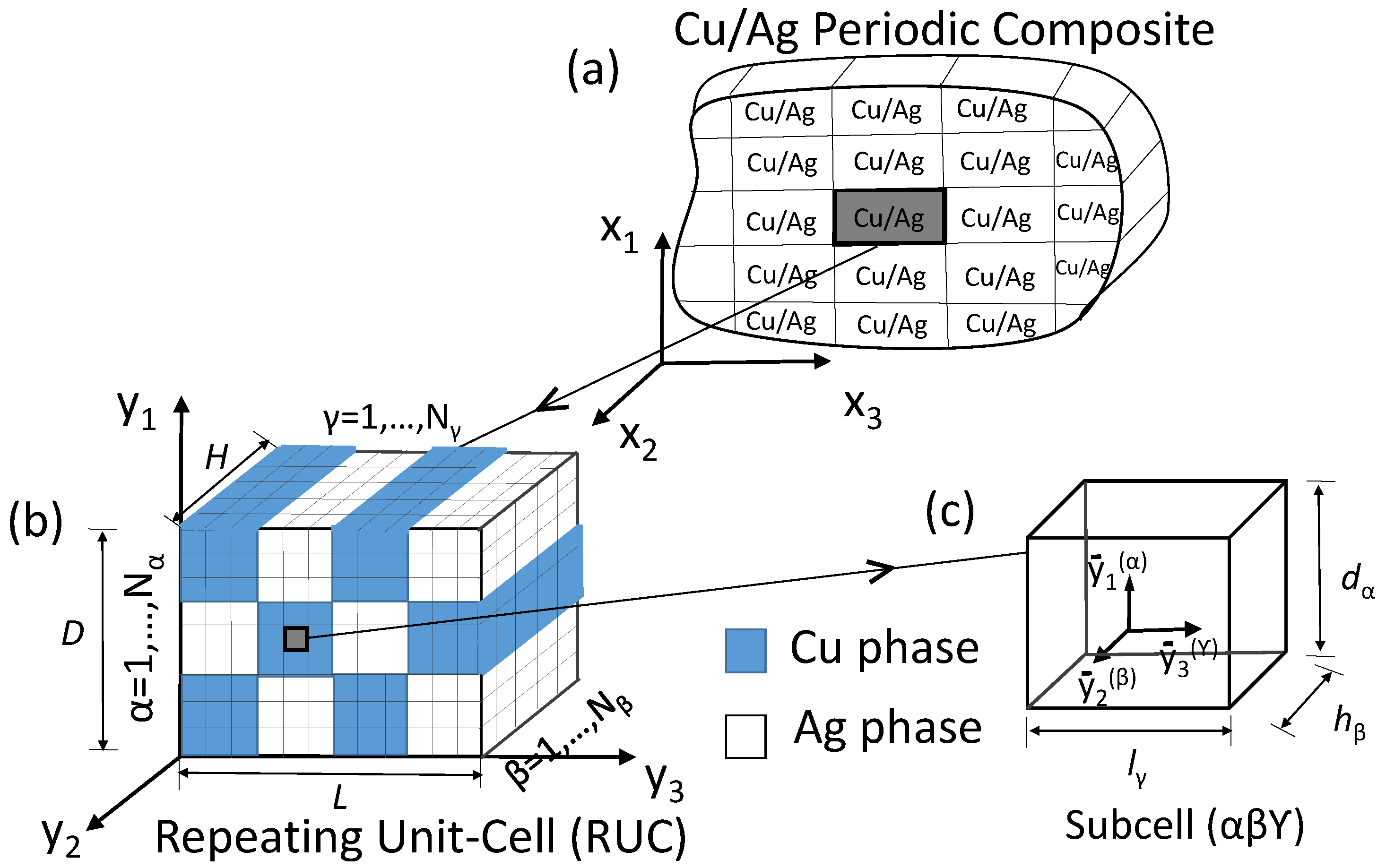
Figure 2.
The macroscopic response of Cu-Ag sample (A) and sample (B) subjected to uniaxial compression loading. Comparison between the high-fidelity generalized method of cells (HFGMC), the experimental results and finite element simulation results [11].
Figure 2.
The macroscopic response of Cu-Ag sample (A) and sample (B) subjected to uniaxial compression loading. Comparison between the high-fidelity generalized method of cells (HFGMC), the experimental results and finite element simulation results [11].
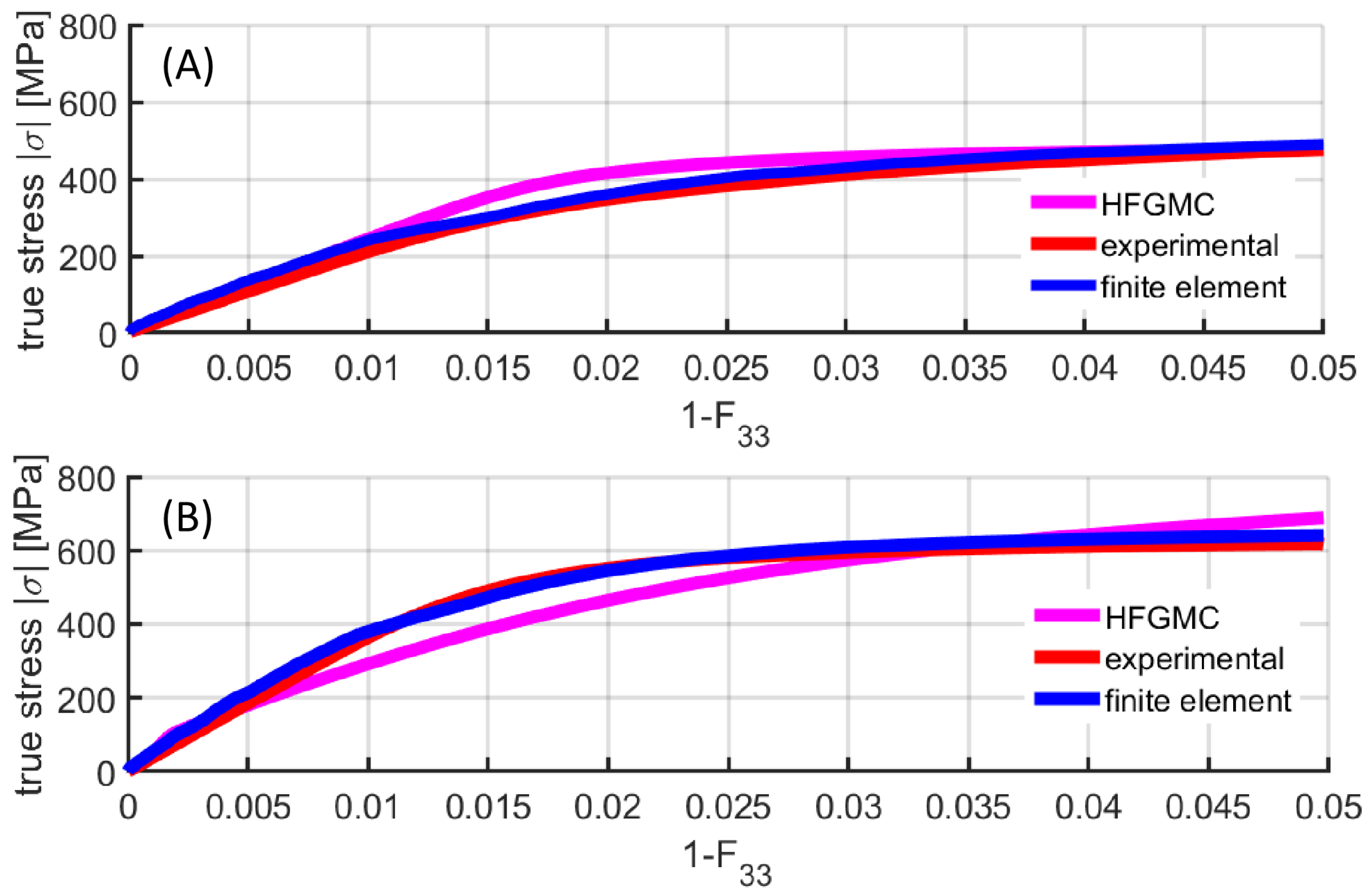
Figure 3.
(a) Material distribution in the plane - at i.e., on the examined cross-section; (b) the induced axial deformation gradient () distribution in the plane - at , i.e., within the RUC of the large sample subjected to uniaxial compression loading; (c) the induced first Piola–Kirchhoff stress () distribution in the plane - at , i.e., within the RUC of the large sample .

Figure 4.
(a) The induced axial deformation gradient () distribution in the plane - at , i.e., within the RUC of the small sample subjected to uniaxial compression loading; (b) the induced first Piola–Kirchhoff stress () distribution in the plane - at , i.e., within the RUC of the small sample .
Figure 4.
(a) The induced axial deformation gradient () distribution in the plane - at , i.e., within the RUC of the small sample subjected to uniaxial compression loading; (b) the induced first Piola–Kirchhoff stress () distribution in the plane - at , i.e., within the RUC of the small sample .


Table 1.
Material parameters.
| Material | () | (MPa) | (MPa) | (MPa) | (MPa) | |
|---|---|---|---|---|---|---|
| sample: | ||||||
| Cu | 0.0001 | 80 | 5.5 | 167.6 | 7964 | 9.2 |
| Ag | 0.0001 | 80 | 5 | 200.9 | 4501 | 20 |
| sample: | ||||||
| Cu | 0.0001 | 80 | 5.5 | 241.4 | 14,000 | 105 |
| Ag | 0.0001 | 80 | 5 | 227.6 | 12,746 | 50 |
© 2017 by the author. Licensee MDPI, Basel, Switzerland. This article is an open access article distributed under the terms and conditions of the Creative Commons Attribution (CC BY) license (http://creativecommons.org/licenses/by/4.0/).
Share and Cite
MDPI and ACS Style
Dodla, S. Micromechanical Analysis for Two-Phase Copper-Silver Composites under Large Deformations. J. Compos. Sci. 2018, 2, 1. https://doi.org/10.3390/jcs2010001
AMA Style
Dodla S. Micromechanical Analysis for Two-Phase Copper-Silver Composites under Large Deformations. Journal of Composites Science. 2018; 2(1):1. https://doi.org/10.3390/jcs2010001
Chicago/Turabian StyleDodla, Srihari. 2018. "Micromechanical Analysis for Two-Phase Copper-Silver Composites under Large Deformations" Journal of Composites Science 2, no. 1: 1. https://doi.org/10.3390/jcs2010001