Laser Irradiation Effects in Simulated Laser-Assisted Machining of Type 316L SS


1
Nuclear AMRC, The University of Sheffield, Sheffield S60 5WG, UK
2
Materials Performance Centre, The University of Manchester, Manchester M13 9PL, UK
*
Author to whom correspondence should be addressed.
J. Manuf. Mater. Process. 2018, 2(3), 45; https://doi.org/10.3390/jmmp2030045
Submission received: 26 June 2018
/
Revised: 9 July 2018
/
Accepted: 11 July 2018
/
Published: 12 July 2018
Abstract
:Laser surface heating allows for the thermal treating of clearly defined surface areas thanks to the ability to focus the laser beam to a specific point. Thus, the rapid heating and subsequent rapid cooling when the beam is moved away, typically associated with laser light, is used as an in-machine process to improve the machinability of hard- or difficult-to-machine alloys. In laser-assisted machining (LAM), laser irradiation occurs simultaneously with materials removal; however, it is difficult to ensure a complete removal of the irradiated areas. In the present work, the two processes were decoupled to investigate the interaction effects of laser radiation type 316L. The surface residual stress, hardness, and microstructure of milled flat specimens were measured prior to and after diode-generated laser beam irradiation. Laser exposure of samples was conducted under protective gas shielding (Argon) using heating parameter combinations that would limit or avoid laser surface melting. Conversely, when the surface underwent melting, the formation of a fast solidification layer resulted in the removal of the cold-worked effect and the significant softening of the surface layers. Beam power density in-homogeneities and incomplete machining of the treated areas in LAM have the potential to introduce significant undesired changes on components’ surface integrity.
1. Introduction
Austenitic stainless steels represent a significant portion of the metals employed in light-water reactors, with types 304L and 316L being the most commonly used stainless-steel alloys used thanks to their high corrosion resistance. Austenitic alloys are employed in the demanding environment of pressurized water reactors (PWR) for an extensive time at temperatures and pressures up to 325 °C and 15 MPa, respectively [1]. Despite their very good corrosion resistance in an aqueous environment, these materials can suffer from environmentally-assisted degradation problems, and some instances of stress corrosion cracking (SCC) in nuclear power plants have occurred [2,3,4,5,6,7]. Amongst the main influencing parameters, surface finish [8,9,10] and residual stresses are the most important. Recent analyses on components removed from boiling water reactors also highlighted the importance of deformation of the surface and surface features, which promote SCC initiation [11,12]. The surface defects originated from manufacturing can also act as a location where crack initiation pre-cursors can occur also due to the promoted local concentration of aggressive ions [13,14].
The machinability of austenitic stainless steels is relatively good, and a significant body of knowledge is available to address the conventional machinability issues caused by its high ductility and high work-hardening coupled with low thermal conductivity [15]. However, the constant drive from the nuclear industry to extend the operative life of plants beyond the 40 years’ limit requires a substantial reduction of the number of manufacturing defects capable of causing accelerated failure of components [16]. Such a requirement requires stringent controls over surface integrity defects from the manufacturing operations and fixes an upper limit on the material removal rate and machining speed with the current manufacturing technologies [17].
The recent increase in demand for carbon-neutral energy has increased the pressure on the nuclear industry to reduce commissioning time and capital costs associated with the installation of new plants, which are notoriously weak points. The strong request for the reduction of commissioning time has subsequently shifted the interest toward the construction of smaller modular reactors (SMRs) which should be offering savings in terms of capital investment and building time. However, SMRs necessitate a large-scale economy to be economically viable, so a minimum number of units per year needs to be produced in order for the process to be competitive with large PWRs [18]. In this scenario, where a good portion of manufacturing costs are strongly linked to machining time, the further reduction of manufacturing-associated costs through the use of advanced machining techniques is being sought after. Several advanced hybrid techniques are available to increase the machinability of difficult materials, such as ultrasonically-assisted machining (UAM), cryogenic and near-cryogenic machining, and laser-assisted machining (LAM). Each one of these techniques has its peculiar range of application, but in general, they offer potential advantages in containing the machining-associated costs and reducing the carbon footprint [19].
Dry machining is generally sought after thanks to its environmentally friendly manufacturing strategy, which does not involve the onerous problem of spent cutting fluid disposal. The increasingly strict environmental protection needs, the health and safety issues associated with operators’ handling of the coolant, the machine energy footprint increase, the cleaning issues, and so on render dry machining of key interest when trying to limit manufacturing impact on the environment [19]. However, dry-machining productivity has an upper limit to the material removal rate due to the maximum thermal dissipation of the tool, which at high removal rates tends to overheat and suffer accelerated wear [20,21]. This issue is partially overcome in LAM, where a laser beam is used to preheat the surface of the metal prior to machining with the aim of reducing its yield stress and ultimately generating minor cutting forces and tool wear [22,23]. In fact, when heated up to temperatures above 500–600 °C, the stainless steels’ strength drops quickly, reaching relatively low values above 800 °C [24]. Decreased strength could result in improved dry-machinability with traditional cutting tools and could be translated into accelerated manufacturing time, thus further reducing the manufacturing-associated costs [25].
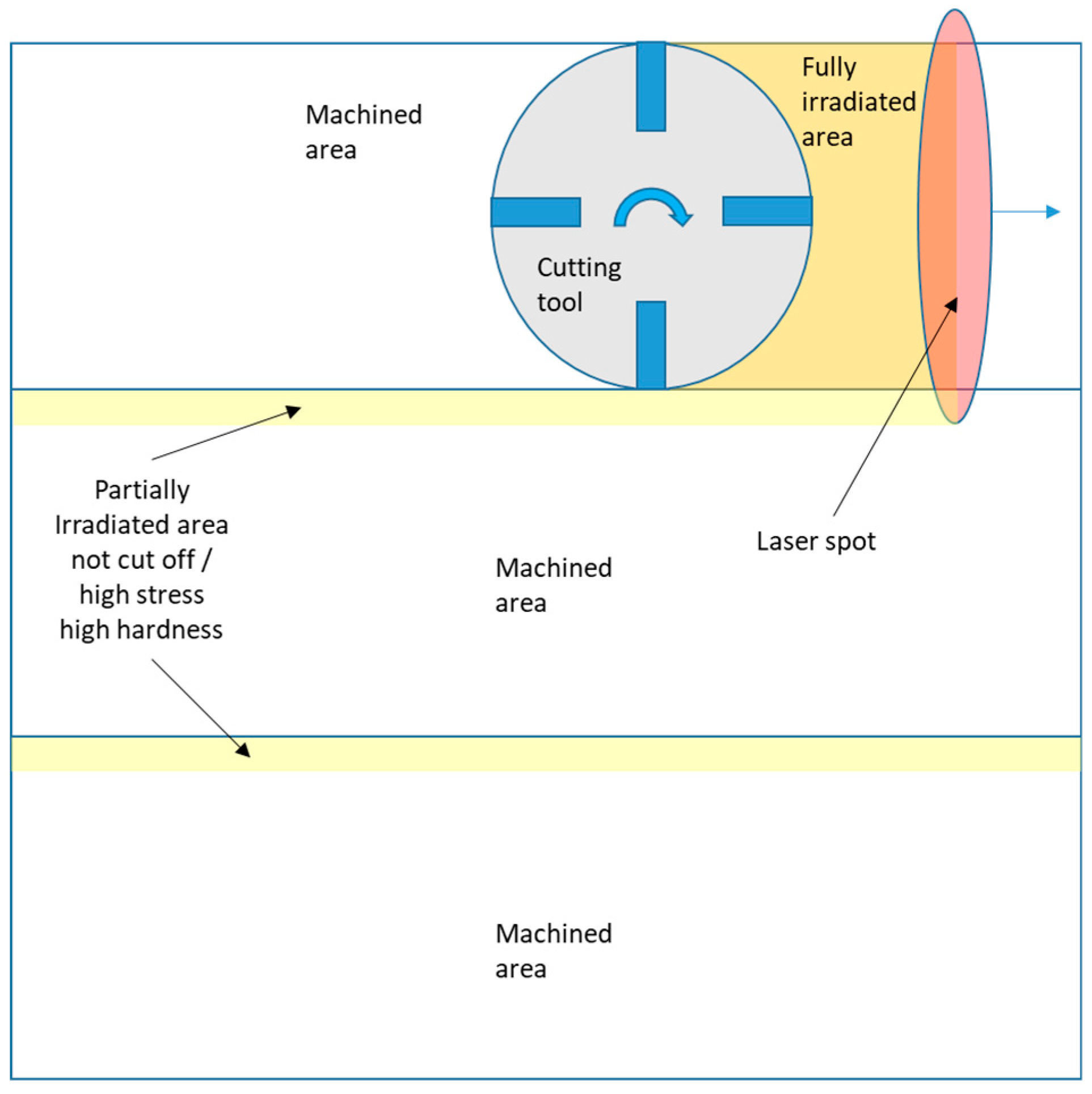
When irradiating the surface of a machining sample with a traveling laser beam, the energy is partially absorbed by the metal and results in a rapid heating of a relatively thin layer of material; afterwards, a rapid cooling occurs by heat conduction to the cold substrate, which acts as a thermal sink. Therefore, the distance between the laser spot and the machining feed must be calibrated accurately if cutting is to occur at the correct temperature. Moreover, laser spot power density distribution inhomogeneity requires an area slightly larger than the cutting tool to be irradiated. When using a rectangular-shaped spot, a top-hat distribution in the transverse direction and a Gaussian in the scan direction, represent the most favorable distributions. It is, however, difficult to obtain very steep slopes in the top-hat distribution, hence the need for the exposure of an area larger than the portion that will undergo machining. This results in partially or fully irradiated areas that are not being removed by the subsequent machining and can lead to the generation of tensile surface stress [26,27,28]. In LAM, the laser beam is placed slightly ahead of the machining tool, and machining happens immediately following irradiation. However, overlapping machining tracks result in scattered areas of pre-heated material, which are not being removed [29]; for parallel machining tracks, this effect is particularly strong with dis-homogeneities in the transverse direction and can result in undesired areas of increased residual surface tensile stress [30,31].
In the present work, machining and irradiation were decoupled to fundamentally understand the implication of laser irradiation on the development of the materials’ properties in order to gain information that could be used to further optimize laser process parameters, ultimately reducing unwanted materials’ modifications. Specifically, AISI 316L plates were first face-milled and subsequently irradiated with a diode laser beam to assess the effects generated on the material. Laser experiments were first conducted in a design of experiment approach to identify the range of parameters, which would be suitable for the consequent tests; they were then followed by scanning laser experiments. This approach allowed the exploration of a wide variation of the key process parameters whilst keeping the total number of trials to a minimum.
Post-irradiation residual stresses were evaluated by X-ray diffraction and compared with the pre-irradiation ones on the surface and at a depth of 50 µm. The morphology of the samples was investigated in cross-section metallography at the scanning electron microscope (SEM) to assess the presence and depth of the modified layers.
2. Experimental Setup
Commercially sourced AISI 316L plates, whose composition and mechanical properties are reported in Table 1, were provided in the hot-rolled state and were cut into square plates with 300 mm side lengths and 75 mm thickness. These plates were machined to remove 1 mm of surface material by face-milling with an 80 mm cutting tool and positive rake (7°) angle with carbide-coated inserts. An emulsion based (10% oil) flood coolant was used to reduce the undesired machining effects, and care was taken to ensure a new insert cutting edge was used. Additional cutting parameters are reported in Table 2.
A high-power fiber-coupled diode laser source from Laserline (LDF 15000-100) with a maximum output power of 15 kW (±2%) and a beam parameter product of 100 mm mrad was used to irradiate the samples. The laser operated in continuous wave mode on a non-monochromatic wavelength of 900–1100 nm. The output beam exiting from the 2 mm core delivery fiber was collimated by a 72 mm focal length lens; a homogenizer (Laserline 2.1) was used to generate the rectangular spot. The beam was then focused on the target at a focal length of 200 mm. Due to the relatively low brilliance of the source, it was possible to operate with a completely focused beam irradiating a rectangular spot of 45 mm × 5.56 mm under a flow of Argon from the head’s coaxial nozzle (nozzle dimensions 10 × 55 mm). Details of the setup can be found in previous works [32].
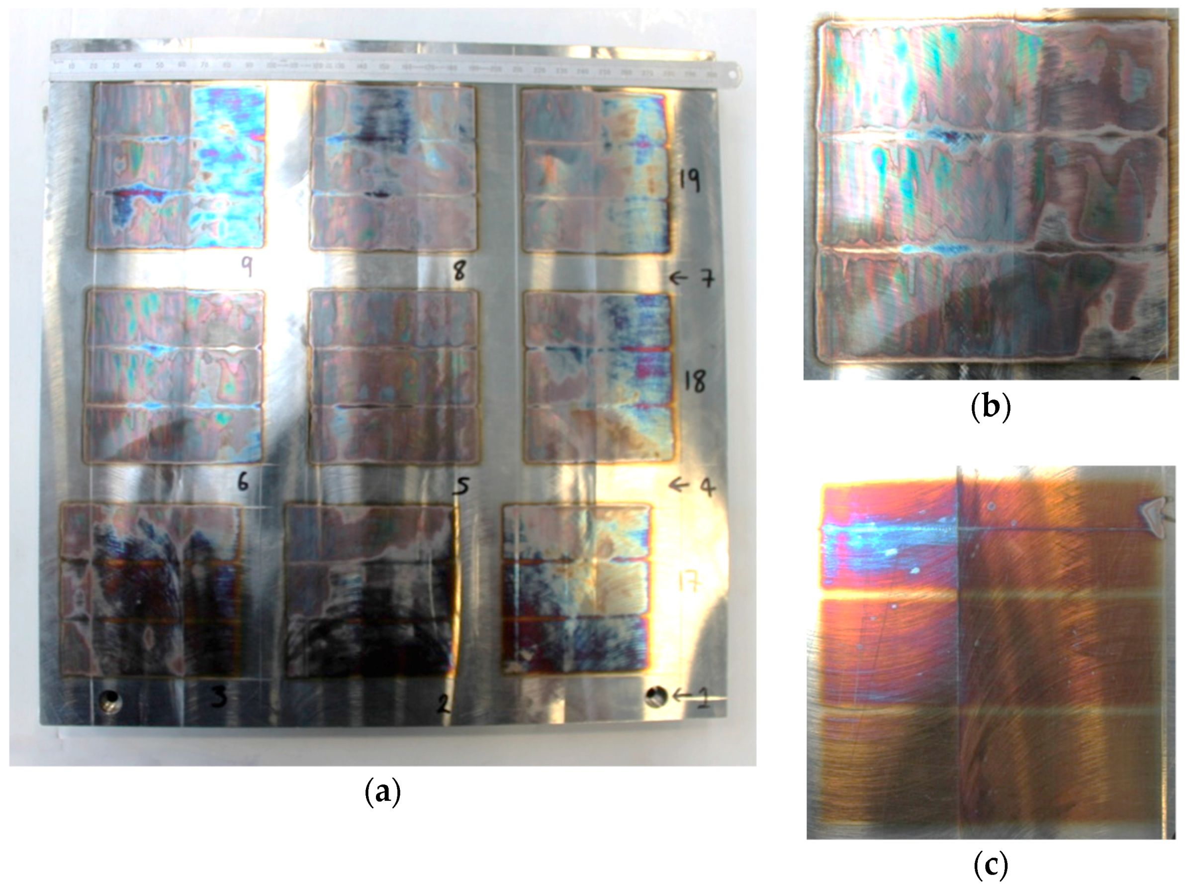
Immediately before irradiation, the samples were carefully degreased using isopropanol and left to dry in air. Nine square (75 mm side length) areas were identified and irradiated in three passes following the order in Figure 1; between each area irradiation, there was a waiting time of 30 s to allow for the cooling of the metal piece. Exposure of the machined coupons to the laser beam was performed following a design of experiments approach aiming to investigate the combination of parameters that did not result in the melting of the surface. The design of experiment laser parameters are presented in Table 3. Care was taken to allow the plate to return to room temperature after each set of exposure (9 areas) before turning the plate for the next lot of exposures. Immediately after irradiation, photographic evidence of the sample was recorded (Figure 1). Figure 1b shows the surface of the sample with a widespread surface melting (LE150), while Figure 1c shows one with incipient surface melting (LE7.5).
The residual stress measurement was performed on a Proto LXRD stress analyzer fitted with a Mn-Kα target tube and operating at 25 kV and 25 mA with a round focused spot of 2 mm diameter. The measurement of surface residual stress in the as-machined specimens was performed by multiple tri-axial measures on three areas of the surface to be irradiated. Care was taken to choose spots far from the edges to avoid gradient effects. The collected groups of results were then averaged to reduce in-homogeneity effects and increase confidence in the measurements; these data are reported in Table 4. The residual stress measurements were repeated in a similar fashion on post-irradiated samples, and variations of the surface stress were also evaluated.
The areas that measured the highest and lowest variation of the surface residual stress (pre- vs. post-irradiation) were selected for further analyses. The residual stress measurements were also performed at a depth of 50 µm (±5 µm) below the surface on the chosen samples by polishing a 20 mm area with an electro-polisher unit (Proto 8818-V3) and a saline electrolyte (Proto Electrolyte A at 42 V) with the assumption that the electro-polishing process would not influence the residual stress. These measurements were compared with 50 µm deep residual stress measurements in areas that were not irradiated.
The sample with the most evident melting (called from now on Sample LE150, see Figure 1b) and the one with the lowest visible melting effects (Sample LE7.5, see Figure 1c) were then sectioned in the cross-section direction (orthogonal to the laser and machining feed) using an emulsion-cooled laboratory rotary saw and hot-mounted in Bakelite and Struers Polyfast conductive resin. The samples were automatically ground using SiC paper disks (grit 100–2500), diamond polished (6 then 1 µm), and finished with OPS Fumed Silica 0.2 µm suspension in water (PH 9.5–10.5). After mounting and polishing, the metallographic mounts were cleaned with isopropanol and dried in a desiccator before the SEM analysis and comparison with cross-section metallographic slides of the “as-machined” samples that did not undergo laser exposure.
The cross-sectioned metallographic specimens were subsequently evaluated using a Phenom World XL SEM operated at 15 kV and equipped with a CeB6 source and a backscatter detector. The cross-section hardness profiles were obtained with a Vickers micro-indenter (Wilson Tukon 2500) at 10 µm intervals up to a depth of 80 µm with a load of 50 g and a dwell time of 15 s resulting in indents of approximately 16–25 µm diagonals.
3. Results
After machining, the test plates showed tensile surface maximum principal residual stress ranging from 60 to 550 MPa with an average of 387 MPa and a median of 400 MPa. The minimum principal stress averaged 154 MPa with a median of 174 MPa. Even if the machining parameters were replicated for each coupon, it was expected to find a noticeable scatter between measurements, as this is the typical behavior in measurements of residual stresses of machined surfaces. Pre-irradiation residual stress data collected from all the machined areas are collated in Table 4.
After irradiation, areas appeared to discolor, with shades ranging from purple to bronze, with bronze being more common when melting occurred. This was a consequence of the inert gas being insufficient to shield completely the sample from oxygen. The variation of the thickness of the formed oxide layer was responsible for the discoloration.
Specifically, averaging the results of all the samples tested (N = 72), the maximum principal stress showed a larger than twofold increase, while the average minimum principal stress increased over four times. It is notable that the difference between the average maximum and minimum principal stresses was reduced after irradiation. Pre-irradiation difference measured 233 MPa and post-irradiation difference only 143 MPa. Standard deviations of the results appeared to be slightly increased after irradiation, but the difference was of little statistical significance.
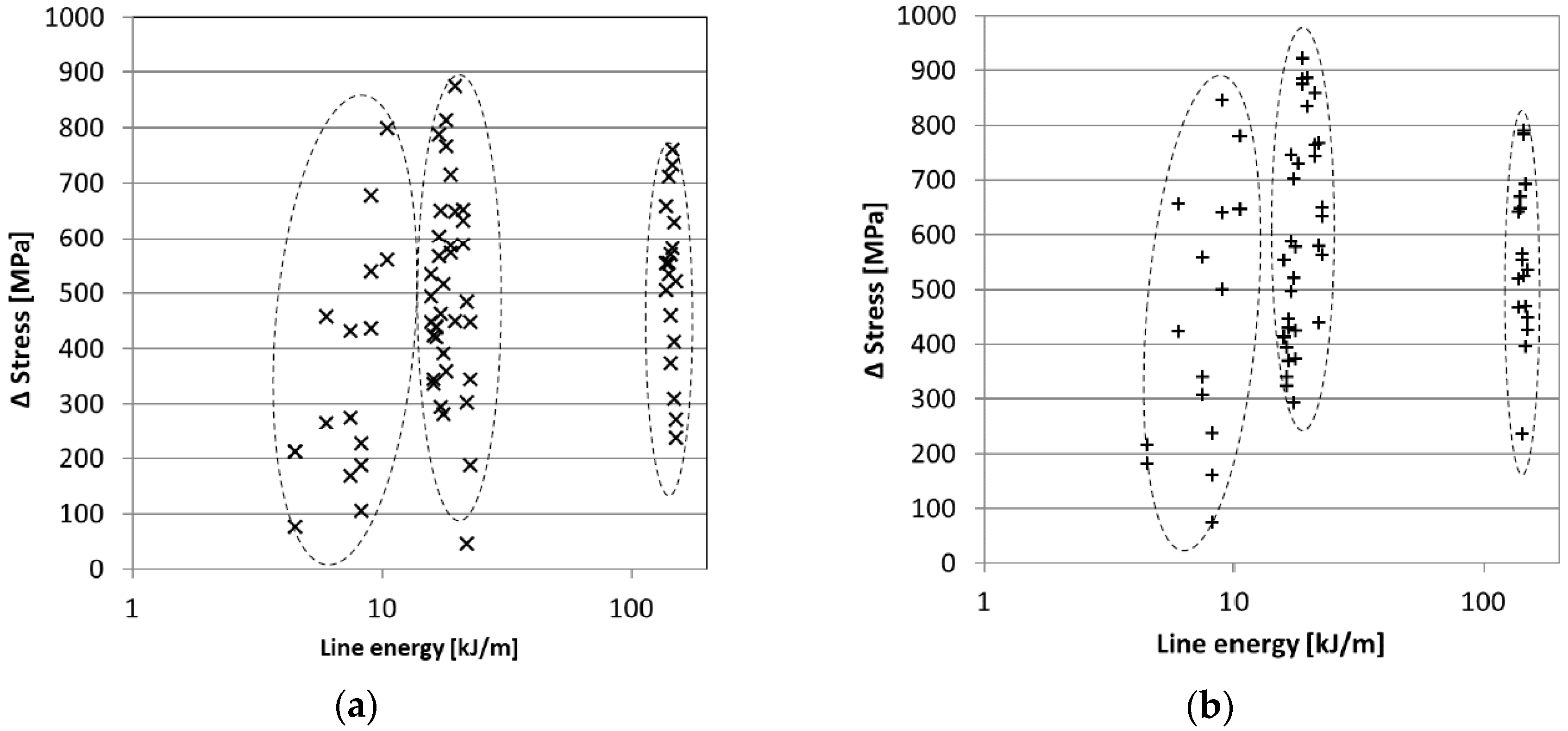
By plotting the differences of the pre- and post-irradiation maximum principal stresses against the line energy, it was possible to identify three zones with a slightly decreasing scatter of the results (Figure 2a).
Similar results were also obtained for the minimum principal stress differences (Figure 2b). A significant scatter in the residual stress differential results was observed after irradiation with a line energy (LE) below 10 kJ/m. The result scatter was reduced as the line energy increased with an apparent minimum occurring for a LE over 120 kJ/m. The scatter of the maximum principal stress differences dropped from the initial 700 MPa (800 MPa for min principal stress) to 550 MPa (600 MPa for minimum principal stress).
The residual stress measured at 50 µm depth for Sample LE150 (LE of 150 kJ/m, laser power of 15 kW, and feed of 100 mm/s) did not appear to vary much (1040 MPa pre-irradiation and 990 MPa post-irradiation). The minimum stress and shear changed significantly: respectively, there was an increase of 675 MPa (with the observation of a stress reversal of the minimum principal stress from −121 MPa to 796 MPa) and a reduction of 360 MPa.
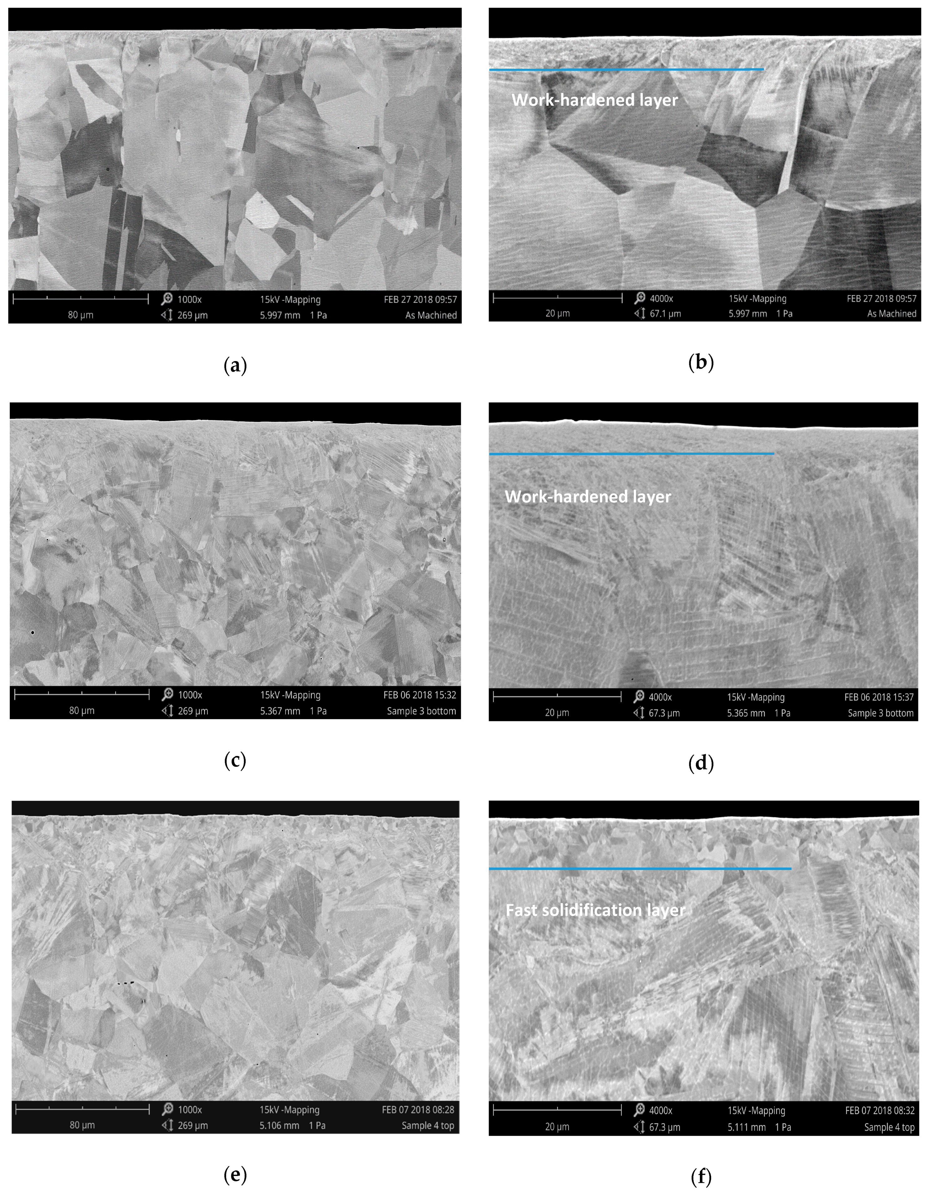
Microstructural characterization was carried out on a selection of the most representative samples, as well as on the baseline material. The cross-section metallographic image of an as-machined sample (Figure 3a,b) showed that grain recrystallization and deformation effects were limited to the first 10 µm with a small zone of equiaxed grains extending for 3–5 µm below the surface. Further deformation, although to a lesser extent, was also visible up to approximately 20 µm but not in a uniform manner across the machined surface.
Cross-section metallographic characterization was also conducted on the laser-irradiated samples and were always taken at least 20 mm from the edges. It was observed a LE threshold value of ~7.5 kJ/m below which surface melting did not occur; this threshold energy was used to treat a sample (Sample LE7.5) used to characterize the laser irradiation effect when no surface melting was observed. In the case where the laser power was 5 kW and the feed rate was 66.7 mm/s, LE was 7.5 kJ/m and melting did not occur; a heavily deformed surface layer was still visible alongside the ultrafine crystallized layer associated with machining, as shown in Figure 3b,c. The depth of the ultrafine recrystallized deformed layer was approximately 5 µm with plastic deformations evident up to a depth of about 10 µm. The thickness of the layer was non-homogeneous, and slight variations were observed in different samples, which are not reported for brevity.
Figure 3e,f shows an example of a different effect on a specimen, which presented surface melting and had a LE of 150 kJ/m (Sample LE150). When superficial melting occurred, the machining-deformed layer melted, and fast solidification led to a lesser grain refinement. It is also interesting to point out that this layer showed no significant deformation, thus confirming the full recovery of the microstructure. The solidification layer was observed to extend up to a depth of 10–15 µm, and unlike the machining-induced deformation layer, it was relatively consistent in thickness. Underneath this melted layer, the grain structure sharply transitioned to the bulk grain structure.
Moreover, as shown in Figure 3e,f, the surface layer in the surface-melted specimens appeared to be significantly coarser and did not show the ultrafine grain structure visible in the specimens that did not undergo surface melting. Conversely, when no melting occurred, the machining-induced layer was preserved (Figure 3b,c).
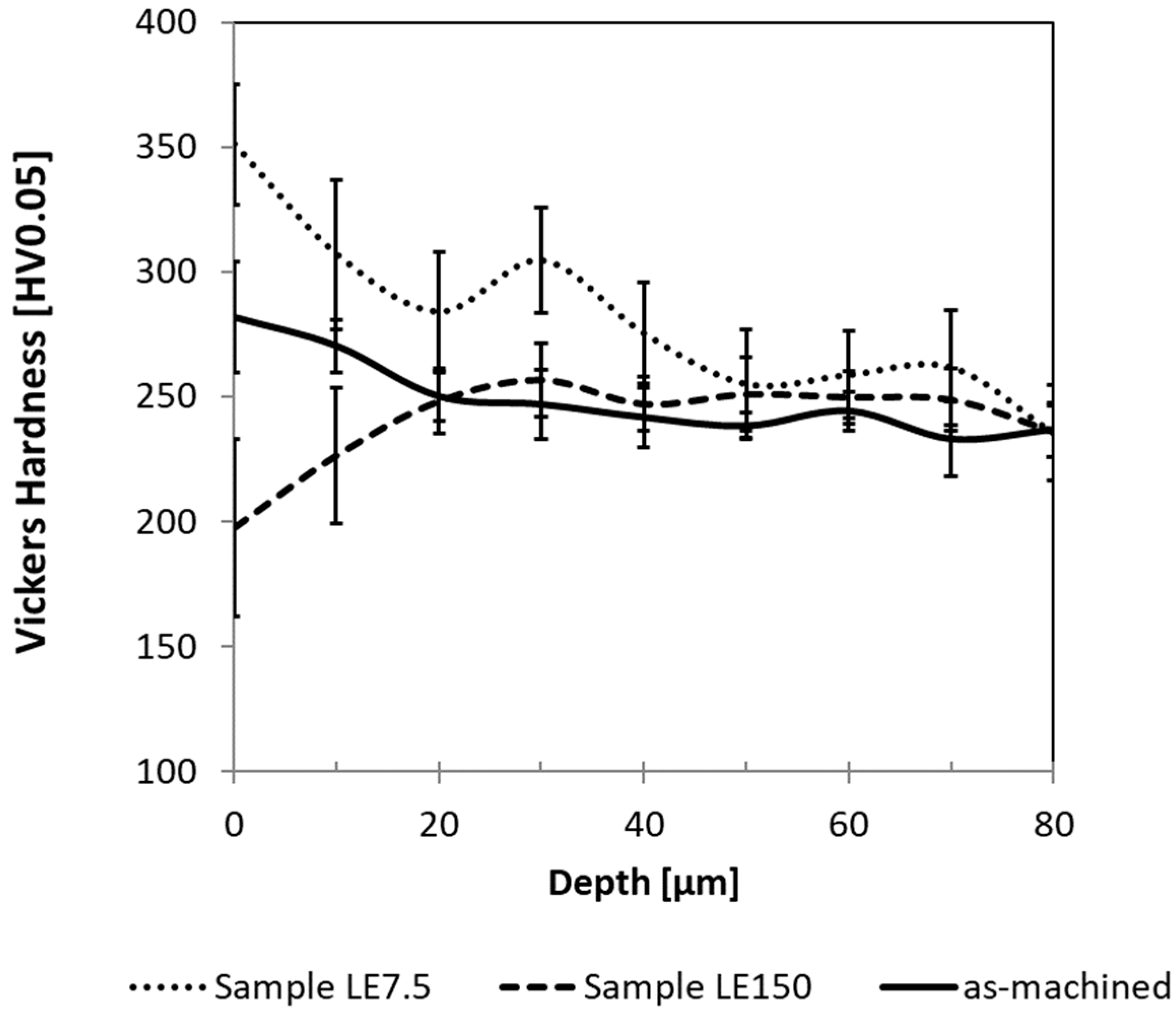
Cross-section micro-hardness measurements were carried out on the as-machined samples, i.e., prior to irradiation, as well as after irradiation on a sample that underwent surface melting (sample LE150) and the one that did not undergo surface melting (sample LE7.5). The results, which are reported in Figure 4, show that in the as-machined sample, there was a surface hardness increase up to ~280 HV within the first 20 µm beneath the surface. The hardness then dropped to the baseline hardness of ~240 HV; these findings are consistent with the cross-sectional characterization and the presence of a surface work-hardened layer. However, upon laser irradiation under conditions that did not induce surface melting (Sample LE7.5), the work-hardened surface layer increased its hardness, which peaked to about 350 HV at the surface, linearly dropped to around 300 HV at a depth of 20 µm, and then remained somewhat constant at 250 HV until the maximum measured depth of 80 µm. Conversely, the sample that was irradiated with a higher value of LE (Sample LE150) presented an opposite trend. Specifically, there was a surface softening, and the hardness had a minimum of 200 HV at the surface, before increasing to around 250 HV at a depth of 30 µm and then remaining constant until a depth of 80 µm at around 250 HV. These results showed that surface melting significantly reduced the surface hardness, whilst the not-melting laser heating treatment significantly increased it. In Figure 4, it is shown that the measured hardness profiles of all samples remained statistically distinct up to a depth of 50 µm below the surface.
4. Discussion
Laser irradiation of the samples’ surfaces resulted in significantly increasing their surface tensile residual stresses. Maximum principal surface stress increased approximately two times, while minimum principal stress increased around four times. In general, there was an increase of all stresses leveling off to a similar value. This could be explained as follows: when processing machined type 316L plates with laser light, thus rapidly increasing the surface temperature, the large thermal expansion coefficient of the materials (α = 16.6 − 19.4 × 10⁻⁶ m/mK, large compared to other steels, as is typical for Austenitic steels [33]) resulted in a significant expansion of the surface layers, which was constrained by the cooler, deeper layers. Eventually, this resulted in plastic deformations with an increasing gradient toward the surface. Once the laser spot traveled further, thus ceasing the localized energy transfer, the heated material underwent a rapid quenching process [34], during which the accumulated heat was dissipated in the cold bulk material by conduction. The once thermally expanded layers contracted, resulting in a tensile stress field being generated on the surface and superimposing on the pre-existent stresses. It is noteworthy to observe that the minimum principal stress prior to irradiation was measured to be compressive in some of the samples. After the heating of the surface and consequent absolute increase of the maximum tensile stress, a reduction of the numerical difference between the maximum and minimum principal stresses was observed.
On this basis, assuming that the work-hardening rate of the material was unchanged, it could be postulated that the surface residual stress increase would be lower on materials with a lower thermal expansion coefficient; conversely, materials with a higher work-hardening rate would be more prone to surface residual stress development. However, more experimental work should be performed to confirm this hypothesis.
It was also shown that effects of laser irradiation on residual stress showed a high scatter at low beam power, but the scatter seemed to reduce for line energies above 10 kJ/m. This effect could be explained as a consequence of the relatively high reflectivity of the machined surfaces, which reflected a significant portion of the laser energy. Reflectance R of type 316L is linked to its emissivity by the following simple relation:
According to Duley [35], it is possible to derive an empirical relationship to calculate the emissivity of CO2 lasers. These, being of sufficiently close wavelength to the diode-beam used in this work, allowed using the same formula to calculate the emissivity changes in accordance with temperature, wavelength, and resistivity of the material:
where T is the temperature in °C, is the resistivity of the material in Ω/cm, and is the temperature coefficient in Ω cm/°C. For type 316L, and . Equation (2) shows that emissivity monotonically increases with temperature; therefore, reflectivity of the alloy was reduced at increased temperatures (cfr. Equation (1)). Because the maximum surface temperature is a function of the energy transferred and therefore of line energy, it was supposed that below a certain level, the effect of the surface texture on the beam absorption would be predominant over the reflectivity changes [35]. At low LE, the surface temperatures were probably lower due to the lower energy transfer. Because the reflectivity changes depend on the temperature, they were small and thus incapable of overcoming the effect of the local in-homogeneity in the surface reflectivity of the material. This ultimately led to a mainly “roughness-driven” reflectivity and, in general, to a less efficient energy transfer process. This transitional regime ultimately resulted in a slightly larger-than-expected spread of the results. At larger line energies it was likely that the specimens’ surface reached higher temperatures due to the heat transfer, and the increased temperature resulted in a larger reduction of its reflectivity. This effect became predominant and able to erase the influence of the local in-homogeneities in reflectivity caused by changes in roughness, ultimately resulting in a more efficient energy transfer. It should also be considered that the oxidation of the surfaces with consequent bluing was more pronounced at higher line energies. If the oxidation process was rapid enough, the bluing of the surface would ultimately reduce its reflectivity, ultimately increasing energy transfer. Reflectivity changes linked to temperature, roughness, and oxidation should be taken into account if a consistent and predictable effect is desired, as the power dis-homogeneities of the laser distribution and inconsistencies in the gas shielding can have a significant effect. The effect of the increasing line energies on residual stress averages resulted in the progressive reduction in the spread of results, as shown in Figure 2. From the same figure, it is possible to conclude that the effects of LE on residual stress were relatively constant with an increase of ~500 MPa of the tensile residual stress after laser treatment when comparing results with the as-machined samples.
When observing the in-depth effect on the residual stress, a reversal of the minimum principal residual stress (−120 MPa to 680 MPa) was observed for Sample LE150. This behavior was likely a consequence of thermal deformations and yielding happening at a depth as low as 50 µm. The maximum principal residual stress was relatively little influenced by depth effect (only 50 MPa change), as it was probably close to the maximum strength of the material (520–670 MPa) with any further increase resulting in yielding. No particular effects were observed on the microstructure of the metal at this depth (50 µm), indicating that the effects of laser exposure on residual stress seemed to extend deeper than those on microstructural changes [36]. Incidentally, no thermal relaxation of stresses was observed due to the thermal transient being extremely brief. As reported by other studies, the laser-treated area was heated up very rapidly and remained for a short time at high temperatures due to the high cooling rate of the heated substrate to the cooler, deeper layers [37].
The machine-hardened layer, which was observed in untreated specimens, was generally thin (3–5 µm ultrafine recrystallized layer, up to 10 µm the total deformed layer). At higher magnifications, the upper layer appeared to be a small equiaxed grain structure. Numerous lath, sub-grain boundaries, and dislocations appeared to concentrate in the layers immediately below the surface up to approximately 10 µm [38,39]. In laser-processed specimens that did not undergo melting, this layer was still clearly visible. Cross-section metallographic slides of surface-melted specimens showed significant changes in the surface microstructure, with the grain refinement effects of machining being deleted and consequent formation of a medium-grained and non-deformed solidification layer. The formation of the solidification layers and phase transformations are commonly observed when treating steel surfaces with lasers [40], but the latter were not observed in this work at the SEM analysis. A notable effect of the appearance of the re-cast layer was a significant reduction of the hardness as the newly formed layer was completely free of deep work-hardening effects, such as those generated during rolling of the material into a plate [41]. Type 316L work-hardening properties usually result in a strongly hardened surface layer after machining; thus, reduction of machined-induced hardness is a desired effect in type 316L. A work-hardening effect was the likely cause of the hardening observed in Sample LE7.5 up to a depth of 50 µm (Figure 4), as thermally-induced expansion in the surface layers resulted in plastic deformations to this depth and consequent strain hardening. It is possible to infer that the increase in hardness observed on the surface of the as-machined and laser-heated specimen would be even higher, because edge effects caused by the vicinity of the boundary between material and resin would result in measuring apparently lower values of hardness. Even taking into account the measured large increase in surface hardness, it was considered unlikely that strain-induced phase transformation processes would happen in this alloy, as its austenitic structure is stabilized by Ni, and, most importantly the 2–3% of Mo increases the stacking fault energy [42,43]. Measurable hardening effects caused by laser heating appeared not to extend below the 50 µm deep layer and are consistent with published work in the literature [44].
Machining is usually the last treatment before the component is put into service, and therefore, it is important to understand the materials’ environmental interaction and their implications on the materials’ performance and stress corrosion cracking. In fact, it is known that the surface finish plays a fundamental role [8,10,45]. After laser irradiation, many surfaces appeared to discolor, especially when higher LE values were employed with consequently higher temperature. The formation of a tarnish was a consequence of the inert gas being insufficient to completely shield the sample from oxidation. Therefore, if laser treatment is employed, it is good practice to remove such films using acid pickling/passivation treatments or mechanically, by shot peening [46], as well as to remove deleterious anionic impurities [13]. This tarnish is not expected to affect the structural integrity of the surface; however, the formation of a heat tint can be detrimental for pitting and localized corrosion. Therefore, care should be taken to avoid surface oxidation. Austenitic stainless steel can be susceptible to SCC in high temperature water [44], for example, in the primary coolant of a reactor. In this specific case, it was found that the ultrafine layer associated with machining had a beneficial effect in retarding SCC initiation, with this beneficial effect overcoming the detrimental effects associated with tensile residual stresses. On this basis, partial surface melting, which was shown to remove the ultrafine-grained layer, increase the pre-existent tensile stress, and cause the formation of a head tint, should be avoided or higher susceptibility to SCC would be expected, both in high temperature water and low temperature atmospheric conditions.
The inevitable in-homogeneities associated with the laser beam power distribution would also lead to the laser exposure of the surface material not later removed by machining (see Figure 5). Carefully designed machining passes, with minimal overlapping, should be employed to ensure that all the partially or totally laser-treated surface would be machined away in order to achieve homogeneity in the materials’ surface properties.
5. Conclusions
Laser heating of type 316L machined specimens negatively impacted their surface residual stresses. Higher tensile stresses were produced on the surface of processed specimens even at minimum line energy. The laser spot size and energy distribution need to be controlled as they strongly influence the resulting surface stress. Because the heating effect persisted until 50 µm, a minimum cutting depth should also be achieved in order to their complete removal. This must be carefully considered in LAM.
In addition to effects on residual stress, microstructural effects were observed when surface melting occurred. Specifically, a strong softening effect consequent to the melting of the pre-existent surface and the formation of a medium-grained fast-solidification structure was identified. The association of this softening effect with the work-hardened layer generated by machining resulted in a surface with variable hardness zones (up to 150 HV difference).
The line energy parameter did not appear to influence the magnitude of residual stress increases, which averaged at around 500 MPa after processing.
Non-uniform surface heating was observed even at low LE due to the hard-to-predict energy transfer caused by the variable surface roughness of the “as-machined” coupons. Given this, employing higher LE resulted in frequent, uncontrolled surface melting, which, in the presence of an insufficient inert gas shielding, ultimately led to a heavy tarnish and poor surface quality. In LAM, the nearby presence of a rapid rotating tool would increase the difficulties in maintaining a sufficient inert gas shielding. Formation of an oxidized layer could result in insufficient corrosion resistance and accelerated SCC of the finished component. Machining in an inert atmosphere would solve the oxidation problem at the price of a more complex and costly manufacturing method.
When attempting LAM in austenitic stainless steel, a significant work in optimizing the process is needed, taking into account the issues associated with shielding from the atmosphere. In order to maintain the materials’ mechanical characteristics and corrosion resistance a prudent selection of the laser and machining parameters and a determination of the correct distance between cutting tool and laser head is needed.
Author Contributions
A.M.: design of experiment, formal analysis, investigation, original draft; F.S.: formal analysis, consideration on corrosion, review of the manuscript; B.K.: design of experiment, laser parameters and control, investigation.
Funding
The McScamp research program, grant number 604965, provided the type 316L steel coupons for experiments, and it is here acknowledged. The authors would like to acknowledge the financial support of the New Nuclear Manufacturing Program (NNUMAN) sponsored by EPSRC (grant EP/JO21172/1).
Acknowledgments
The authors wish to acknowledge the United Kingdom (UK) High Value Manufacturing Catapult for sponsoring this project. The authors are thankful to Nuclear AMRC research board that funded this work and the assistance of its staff. Thanks to B. Baufeld and T. Syed for their assistance in this work.
Conflicts of Interest
The authors declare no conflict of interest.
References
- Nanstad, R.K. Encyclopedia of Material Science and Engineering; Pergamon: New York, NY, USA, 1986. [Google Scholar]
- Couvan, T.; Legras, L.; Pokor, C.; Vaillant, F.; Brechet, Y.; Boursier, J.; Moulart, P. Investigations on the machanism of PWSCC of strain hardened austenitic stainless steels. In Proceedings of the 13th International Conference on Environmental Degradation of Materials in Nuclear Power Systems, Whistler, BC, Canada, 19–23 August 2007. [Google Scholar]
- Cissé, S.; Laffont, L.; Tanguy, B.; Lafont, M.-C.; Andrieu, E. Effect of surface preparation on the corrosion of austenitic stainless steel 304L in high temperature steam and simulated PWR primary water. Corros. Sci. 2012, 56, 209–216. [Google Scholar] [CrossRef] [Green Version]
- Gupta, J.; Hure, J.; Tanguy, B.; Laffont, L.; Lafont, M.-C.; Andrieu, E. Evaluation of stress corrosion cracking of irradiated 304L stainless steel in PWR environment using heavy ion irradiation. J. Nucl. Mater. 2016, 476, 82–92. [Google Scholar] [CrossRef] [Green Version]
- Tribouilloy, L.; Vaillant, F.; Olive, J.; Puiggali, M.; Legras, L.; Couvant, T.; Boursier, J.; Rouillon, Y.; Amzallag, C. Stress corrosion cracking on cold-worked austenitic stainless steels in PWR environment. Adv. Mater. Sci. 2007, 7, 61–69. [Google Scholar]
- Raquet, O.; Herms, E.; Vaillant, F.; Couvant, T.; Boursier, J.-M. SCC of cold-worked austenitic stainless steels in PWR conditions. In Proceedings of the 12th International Symposiom on Environmental Degradation of Materials in Nuclear Power Reactors, Salt Lake City, UT, USA, 14–18 August 2005; pp. 1049–1058. [Google Scholar]
- Yonezawa, T.; Watanabe, M.; Atsushi, H. Effect of work hardened inner surface layers on stress corrosion cracking of type 316 stainless steel and TT alloy 690 in simulated PWR primary water. In Proceedings of the 17th International Conference on Environmental Degradation of Materials in Nuclear Power Systems—Water Reactors, Ottawa, ON, Canada, 9–13 August 2015; pp. 496–513. [Google Scholar]
- Han, G.; Lu, Z.; Ru, X.; Chen, J.; Xiao, Q.; Tian, Y. Improving the oxidation resistance of 316L stainless steel in simulated pressurized water reactor primary water by electropolishing treatment. J. Nucl. Mater. 2015, 467, 194–204. [Google Scholar] [CrossRef]
- Han, Y.; Mei, J.; Peng, Q.; Han, E.-H.; Ke, W. Effects of electropolishing on corrosion of Alloy 600 in high temperature water. Corros. Sci. 2015, 98, 72–80. [Google Scholar] [CrossRef]
- Han, Y.; Mei, J.; Peng, Q.; Han, E.-H.; Ke, W. Effect of electropolishing on corrosion of nuclear grade 316L stainless steel in deareated high temperature water. Corros. Sci. 2016, 112, 625–634. [Google Scholar] [CrossRef]
- Miura, Y.; Miyahara, Y.; Sato, M.; Kako, K.; Tani, J.I. Behaviour of Stress Corrosion Cracking for Type 316L Stainless Steel with Controlled Distribution of Surface Work Hardened Layer in Simulated Boiling Water Reactors Environment; Ilevbare, G., Andersen, P.L., Busby, J.T., Eds.; Wiley Online Library: Hoboken, NJ, USA, 2011; pp. 439–449. [Google Scholar]
- Miura, Y.; Miyahara, Y.; Kako, K.; Sato, M. Effects of Plastic Strain and Stress Distribution on SCC Initiation in High Temperature Water. In Proceedings of the Corrosion 2013, Orlando, FL, USA, 17–21 March 2013. [Google Scholar]
- Scenini, F.; Sherry, A. Stress Corrosion Cracking of Sensitized Type 304 Stainless Steel in High-Temperature Water with Anionic Impurities Contamination. Corrosion 2012, 68, 1094–1107. [Google Scholar] [CrossRef]
- Shoji, T. Progress in the mechanistic understanding of BWR SCC and its implication to the prediction of SCC growth behaviour in plants. In Proceedings of the 11th Symposium on Environmental Degradation of Materials in Nuclear Power Systems—Water Reactors, Stevenson, WA, USA, 10–14 August 2003; pp. 588–598. [Google Scholar]
- Tetal, K. Machining of Stainless Steels. In ASM Handbook: Machining; Davis, J.R., Ed.; ASM International: Materials Park, OH, USA, 1989. [Google Scholar]
- Klueh, R.L.; Nelson, A.T. Ferritic/Martensitic steels for next-generation reactors. J. Nucl. Mater. 2007, 371, 37–52. [Google Scholar] [CrossRef]
- Groover, M.P. Fundamental of Modern Manufacturing—Materials Processes and Systems; Prentice-Hall: Englewood Cliffs, NJ, USA, 1990. [Google Scholar]
- Boarin, S.; Mancini, M.; Ricotti, M.; Locatelli, G. Economics and financing of small modular reactors. In Handbook of Small Modular Nuclear Reactors; Ingersoll, D.T., Carelli, M.D., Eds.; Woodhead Publishing Series in Energy; Woodhead Publishing Limited: Cambridge, UK, 2015. [Google Scholar]
- Byrne, G.; Scholta, E. Environmentally clean machining processes—A strategic approach. CIRP Ann. Manuf. Technol. 1993, 42, 471–474. [Google Scholar] [CrossRef]
- Ezugwu, E.; Wang, Z.; Machado, A. The machinability of nickel-based alloys: A review. J. Mater. Process. Technol. 1999, 86, 1–16. [Google Scholar] [CrossRef]
- Alauddin, M.; El Baradie, M.; Hashmi, M. End-milling machinability of Inconel 718. J. Eng. Manuf. 1996, 210, 11–23. [Google Scholar] [CrossRef]
- Attia, H.; Tavakoli, S.; Vargas, R.; Thomson, V. Laser-assisted high-speed finish turning of superalloy Inconel 718 under dry conditions. CIRP Ann. Manuf. Technol. 2010, 59, 83–88. [Google Scholar] [CrossRef]
- Tönshoff, H.K.; Arendt, C.; Amor, R.B. Cutting of hardened steels. CIRP Ann. Manuf. Technol. 2000, 49, 547–566. [Google Scholar] [CrossRef]
- American Iron and Steel Institute. High-Temperature Characteristics of Stainless Steels; A Designers’ Handbook Series; Nickel Development Institute: Toronto, ON, Canada, 2013. [Google Scholar]
- Anderson, M.; Patwa, R.; Shin, Y.C. Laser-assisted machining of Inconel 718 with an economic analysis. Int. J. Mach. Tools Manuf. 2006, 46, 1879–1891. [Google Scholar] [CrossRef]
- Germain, G.; Lebrun, J.-L.; Braham-Bouchnak, T.; Bellett, D.; Auger, S. Laser assisted machining of Inconel 718 with carbide and ceramic inserts. Int. J. Mater. Form. 2008, 1, 523–526. [Google Scholar] [CrossRef] [Green Version]
- Ding, H.; Shin, Y.C. Laser-assisted machining of hardened steel parts with surface integrity analysis. Int. J. Mach. Tools Manuf. 2010, 50, 106–114. [Google Scholar] [CrossRef]
- Germain, G.; Dal Santo, P.; Lebrun, J. Comprehension of chip formation in laser assisted machining. Int. J. Mach. Tools Manuf. 2011, 51, 230–238. [Google Scholar] [CrossRef] [Green Version]
- Woodard, P.R.; Dryden, J. Thermal analysis of a laser pulse for discrete spot surface transformation hardening. J. Appl. Phys. 1999, 85, 2488–2496. [Google Scholar] [CrossRef]
- Giorleo, L.; Previtali, B.; Semeraro, Q. Modelling of back tempering in laser hardening. Int. J. Adv. Manuf. Technol. 2011, 54, 969–977. [Google Scholar] [CrossRef]
- Kennedy, E.; Byrne, G.; Collins, D.N. A review of the use of high power diode lasers in surface hardening. J. Mater. Process. Technol. 2004, 155, 1855–1860. [Google Scholar] [CrossRef]
- Lubaszka, P.; Baufeld, B. Powder Blown Laser Cladding of Vertical Surfaces. Lasers Eng. 2018, 39, 35–52. [Google Scholar]
- Atlas Steels. Stainless Steel Grade Datasheets; Atlas Steels Technical Department: Melbourne, Australia, 2013. [Google Scholar]
- Shi, B.; Attia, H.; Vargas, R.; Tavakoli, S. Numerical and experimental investigation of laser-assisted machining of Inconel 718. Mach. Sci. Technol. 2008, 12, 498–513. [Google Scholar] [CrossRef]
- Duley, W.W. CO2 Laser: Effects and Applications; Academic Press: New York, NY, USA, 1976. [Google Scholar]
- Chen, C.H.; Ju, C.P.; Rigsbee, J.M. Laser surface modification of ductile iron: Part 1 microsctructure. Mater. Sci. Technol. 1988, 4, 161–166. [Google Scholar] [CrossRef]
- Tricarico, L.; Ancona, A.; Palumbo, G.; Sorgente, D.; Spina, R.; Lugarà, P.M. Discrete spot laser hardening and remelting with a high-brilliance source for surface structuring of a hypereutectoid steel. Mater. Des. 2017, 115, 194–202. [Google Scholar] [CrossRef]
- Maurotto, A.; Tsivoulas, D.; Burke, M.G. Surface Integrity in Dry Milling of 304L Steel: A Parametric Study. Procedia CIRP 2014, 13, 156–162. [Google Scholar] [CrossRef]
- Maurotto, A.; Tsivoulas, D.; Gu, Y.; Burke, M.G. Effects of machining abuse on the surface properties of AISI 316L stainless steel. Int. J. Press. Vessel. Pip. 2017, 151, 35–44. [Google Scholar] [CrossRef] [Green Version]
- Soriano, C.; Leunda, J.; Lambarri, J.; Navas, V.G.; Sanz, C. Effect of laser surface hardening on the microstructure, hardness and residual stresses of austempered ductile iron grades. Appl. Surf. Sci. 2011, 257, 7101–7106. [Google Scholar] [CrossRef]
- Yanushkevich, Z.; Dobatkin, S.V.; Belyakov, A.; Kaibyshev, R. Hall-Patch relationship for austenitic stainless steels processed by large strain warm rolling. Acta Mater. 2017, 136, 39–48. [Google Scholar] [CrossRef]
- Meric de Bellefon, G.; Domain, C.; van Duysen, J.C.; Sridharan, K. Composition-dependence of stacking fault energy in austenitic stainless steels through regression analysis. In Proceedings of the 2016 International Congress on Advances in Nuclear Power Plants, San Francisco, CA, USA, 17–20 April 2016. [Google Scholar]
- Dai, Q.-X.; Wang, A.-D.; Cheng, X.-N.; Luo, X.-M. Stacking fault energy of cryogenic austenitic steels. Chin. Phys. 2002, 11, 595–600. [Google Scholar]
- Chang, L.; Duff, J.; Burke, M.G.; Scenini, F. SCC Initiation in the Machined Austenitic Stainless Steel 316L in Simulated PWR Primary Water. In Proceedings of the 18th International Conference on Environmental Degradation of Materials in Nuclear Power Systems—Water Reactors, Portland, OR, USA, 13–17 August 2017. [Google Scholar]
- Scenini, F.; Newman, R.C.; Cottis, R.A.; Jacko, R.J. Effect of Surface Preparation on Intergranular Stess Corrosion Cracking of Alloy 600 in Hydrogenated Steam. Corrosion 2008, 64, 824–835. [Google Scholar] [CrossRef]
- Turthill, A.H. Fabrication and Post-Fabrication Clean-Up of Stainless Steel (10004); Nickel Development Institute: Toronto, ON, Canada, 1986. [Google Scholar]
Figure 1.
(a) Irradiated plate; (b) Sample LE150 (plate D top); (c) Sample LE7.5 (plate C top).

Figure 2.
(a) Maximum principal surface stress differences vs. line energy; (b) Minimum principal surface stress differences vs. line energy; result grouped according to line energy (LE).
Figure 2.
(a) Maximum principal surface stress differences vs. line energy; (b) Minimum principal surface stress differences vs. line energy; result grouped according to line energy (LE).

Figure 3.
Cross-section SEM slides of irradiated specimens: (a,b) as-machined; (c,d) sample LE7.5 showing no surface melting effects; (e,f) sample LE150 showing significant melting effects (layers indicated in the captioning).
Figure 3.
Cross-section SEM slides of irradiated specimens: (a,b) as-machined; (c,d) sample LE7.5 showing no surface melting effects; (e,f) sample LE150 showing significant melting effects (layers indicated in the captioning).

Figure 4.
Cross-section hardness profile for heated (Sample LE7.5), surface-melted (Sample LE150), and as-machined specimens.
Figure 4.
Cross-section hardness profile for heated (Sample LE7.5), surface-melted (Sample LE150), and as-machined specimens.

Figure 5.
Partial irradiation effects on straight-cut face-milling.


Table 1.
316L sample chemical composition (wt %) and mechanical properties.
| C | Si | Mn | Cr | Ni | Mo | N | S | Co | P | Fe |
|---|---|---|---|---|---|---|---|---|---|---|
| 0.12 | 0.31 | 1.78 | 16.60 | 10.18 | 2 | 0.404 | 0.001 | 0.15 | 0.04 | balance |
| σy0.2% (MPa) | σy1% (MPa) | UTSmax (MPa) | Hardnessmax (HB) | Toughness (J) | Br. Elongation (A5%) | |||||
| 220 | 260 | 670 | 217 | 60 (20 °C) | 45 | |||||
Table 2.
Machining data.
| Depth of Cut ap | 0.2 mm |
| Spindle speed ω | 550 RPM |
| Feed rate f | 200 mm/min |
| Cooling | Low pressure flood coolant |
| Cutting tool | 345-080027-13HX-M617910 |
| Cutting center | Mazak Vertical Center Smart 430A |
Table 3.
Laser parameters.
| Coupon | Laser Power (kW) | LE (kJ/m) | Feed (mm/s) |
|---|---|---|---|
| Plate A top | 7–7.5 | 21.02–22.50 | 33.3 |
| Plate A bottom | 6–6.5 | 18.01–19.52 | 33.3 |
| Plate B top | 11.25–11.75 | 16.85–17.62 | 66.7 |
| Plate B bottom | 10.5–11 | 15.75–16.48 | 66.7 |
| Plate C top | 3–5 | 4.5–7.5 | 66.7 |
| Plate C bottom | 5.5–7 | 8.25–10.49 | 66.7 |
| Plate D top | 14.5–15 | 145–150 | 100 |
| Plate D bottom | 13.75–14.25 | 137.5–142.5 | 100 |
Table 4.
Pre- and post-irradiation surface residual stress.
| Pre-Irradiation Surface Residual Stress | Post-Irradiation Surface Residual Stress | ||
|---|---|---|---|
| Statistical Parameter | Value (MPa) | Statistical Parameter | Value (MPa) |
| Average max principal stress | 387 | Average max principal stress | 855 |
| Median max principal stress | 400 | Median max principal stress | 899 |
| STD max principal stress | 152 | STD max principal stress | 211 |
| Average min principal stress | 154 | Average min principal stress | 711 |
| Median min principal stress | 174 | Median min principal stress | 767 |
| STD min principal stress | 192 | STD min principal stress | 197 |
© 2018 by the authors. Licensee MDPI, Basel, Switzerland. This article is an open access article distributed under the terms and conditions of the Creative Commons Attribution (CC BY) license (http://creativecommons.org/licenses/by/4.0/).
Share and Cite
MDPI and ACS Style
Maurotto, A.; Scenini, F.; Kraemer, B. Laser Irradiation Effects in Simulated Laser-Assisted Machining of Type 316L SS. J. Manuf. Mater. Process. 2018, 2, 45. https://doi.org/10.3390/jmmp2030045
AMA Style
Maurotto A, Scenini F, Kraemer B. Laser Irradiation Effects in Simulated Laser-Assisted Machining of Type 316L SS. Journal of Manufacturing and Materials Processing. 2018; 2(3):45. https://doi.org/10.3390/jmmp2030045
Chicago/Turabian StyleMaurotto, Agostino, Fabio Scenini, and Bjoern Kraemer. 2018. "Laser Irradiation Effects in Simulated Laser-Assisted Machining of Type 316L SS" Journal of Manufacturing and Materials Processing 2, no. 3: 45. https://doi.org/10.3390/jmmp2030045