Degradable Nanocomposites for Fused Filament Fabrication Applications


Applied Polymer Technologies Gateway, Materials Research Institute, Athlone Institute of Technology, Dublin Road, Athlone, N37 HD68 County Westmeath, Ireland
*
Author to whom correspondence should be addressed.
J. Manuf. Mater. Process. 2018, 2(2), 29; https://doi.org/10.3390/jmmp2020029
Submission received: 23 March 2018
/
Revised: 5 May 2018
/
Accepted: 7 May 2018
/
Published: 9 May 2018
Abstract
:There has been a substantial increase in the use and development of plastics over the last century. However, due to ever-diminishing petroleum feedstocks and growing concern for the environment, there has been a rise in the use of eco-friendly polymers affording similar properties to that of their depleting counterparts. Poly(ε-caprolactone) is one such polymer. This present study investigates the possibility of developing a degradable nanocomposite, suitable for fused filament fabrication, utilizing hot melt extrusion technology to blend poly(ε-caprolactone), poly(ethylene) oxide and the nanoclay halloysite at loadings of two and six weight percent. The extruded blends were characterized using common polymer testing techniques. The addition of poly(ε-caprolactone) to the poly(ethylene) oxide matrix provided a plasticizing effect which was apparent with the melt flow index and melting point of the blends reducing with an increase in poly(ε-caprolactone) content. Upon reinforcing the matrix with halloysite, there was a significant improvement in mechanical properties. The addition of halloysite significantly increased Young’s modulus 11% and 25% when the loading was two and six percent respectively. Furthermore, it was also possible to produce a filament with the desired properties, diameter 1.75 mm, for fused filament fabrication, with subsequent studies required to evaluate their printability.
1. Introduction
The use of plastics in everyday life has increased dramatically during the course of the 20th and 21st century which is primarily due to the characteristics that plastics offer in the development of new products to meet the challenges in modern society. Silverman et al. [1] reported that in 2015, approximately 300 million tons of plastic material will be produced around the world, most of which will be derived from the ever depleting petroleum feedstocks and this has resulted in them attracting increasing interest owing to the growing concern with regards to both the environment and decrease in fossil resources [2].
As a direct result, this has led to a substantial interest in switching to suitable eco-friendly alternatives of already existing polymers as well as developing new low-cost polymers which have competitive performance properties from feedstocks that are available from renewable stock resources [3]. Over the last several decades, the study of both resorbable and degradable polymers has been investigated to a great extent [4], with the vast majority, e.g., poly(ε-caprolactone) (PCL), polyvinyl alcohol (PVA) and polylactide acid (PLA), being produced from renewable sources [5].
Poly(ε-caprolactone) is a linear synthetic biodegradable aliphatic polyester and was one of the earliest polymers synthesized by the Carothers group in the early 1930s [6,7]. PCL is a hydrophobic, semi-crystalline polymer exhibiting a melting point in the range of 59–64 °C [8]. The degradation time of the homopolymer is approximately two years [9] which is attributed to the five hydrophobic methylene (CH2) moieties which are present in its repeating unit [10] with higher molecular weight structures taking much longer to degrade. It is this degradation characteristic in vivo compared to other biodegradable polymers which makes PCL suitable for the development of controlled release drug delivery devices and suture materials [11]. Further to this, PCL and PCL-based materials and devices have found applications in the areas of artificial implants, tissue engineering and three dimensional (3D) printing [6] which has the potential to revolutionize the way in which patients’ needs may be met with regards to personalized medicine and has been reported elsewhere [12,13].
Fuenmayor and researchers [13] utilized a variety of polymers, including poly(ε-caprolactone) and poly(ethylene oxide), and conducted a study to investigate drug release profiles from two distinctively different manufacturing techniques: direct compaction and fused filament fabrication (FFF), the former being a conventional method and the latter one of emerging interest. The results from their study found that the presence of PCL retarded the release of the drug particularly the FFF dosage form as only 38.5% of drug released after a duration of six hours in comparison to a 78.3% release in the direct compaction dosage form (PCL content 55%) [13]. This illustrates that PCL has the potential to be utilized in the production of controlled drug release formulations by FFF and particularly in tailoring the release profile specific to a patient’s requirements by modification of PCL content.
Furthermore, PCL has also found applications in the areas of tissue engineering (TE) with research carried out by Patrício and researchers [14,15,16] demonstrating how it may be used in the fabrication of scaffolds for tissue engineering. In the vast research, they published they fabricated both PCL and PCL/PLA scaffolds utilizing a novel additive biomanufacturing technique of BioCell Printing with the researchers concluding that it was possible to produce scaffolds which were both accurate and reproducible in addition to improved biological and mechanical properties [14,15,16]. Further research conducted by Borzacchiello [17] also evaluated PCL and the potential of producing porous scaffolds using the BioCell Printing technique combining both natural and synthetic polymers for tissue engineering applications. The authors established that the combination of PCL and a derivative of hyaluronic acid demonstrated the potential for fibrocartilage tissue engineering applications due to the characteristics with regard to the structural, mechanical and biological properties the scaffolds displayed.
Poly(ethylene oxide) (PEO) is a non-ionic, highly hydrophilic, water-soluble synthetic polyether that may be branched or linear. PEO like PCL is a semi-crystalline polymer and has a melting point in the range of 57–73 °C [18] with Spietelun et al. [19] indicating that the melting point of PEO increases with increasing molecular weight. PEO is highly biocompatible with a low toxicity rendering it particularly suited to drug delivery applications [20] with a vast amount of literature published with regard to PEO being utilized in the preparation of various dosage forms.
Park et al. [21] conducted a study to characterize the interaction between PEO/PCL in the release of the drug, erythromycin, from microcapsules and found that the increase of PEO content increased drug release from the microcapsules demonstrating the potential PEO offers for controlled release technologies. Furthermore, a team of researchers led by Lyons in 2006 [22] investigated the use of nanoclay particles as a novel filler material for the development of oral dosage forms with PEO present in the polymeric matrix as PEO has demonstrated in a study by Zhang and McGinity [23] useful for modulating the release of drug from matrix tablets fabricated by hot melt extrusion technology. Additionally, PEO has also found applications in the areas of TE with Kenny and researchers [24] investigating its suitability in tissue regenerating applications. From the study, it was concluded that altering the ratio of PEO to PCL has the potential to tailor the degradation rate of the polymeric matrix over a specified time period.
Further to this, Grehan et al. [25] evaluated the potential of melt blending novel fillers, chitosan and k-carrageenan, into a polymeric matrix composed of PEO and PCL and studied the release rate of 4-acetaminophenol (Acetaminophen) from matrix tablets produced by hot melt extrusion. The researchers demonstrated that the addition of the fillers altered the rate at which the drug was released when compared to the matrix that contained no fillers illustrating that inclusion of these fillers could be utilized in the production of controlled release polymer composite materials for drug delivery systems.
It has been reported by Bordes and co-authors [2] that nanocomposites are novel materials which have the ability to dramatically improve the properties of polymers such as increasing mechanical strength and thermal resistance [26,27,28,29]. Halloysite nanotubes (HNTs) are one such nanomaterial that has been utilized with polymers in the development of nanocomposites. Tzounis and researchers [29] conducted a study in which they modified HNTs and prepared polystyrene/halloysite (PS/HNT) nanocomposites. From their study, the authors concluded that all nanocomposites illustrated improved thermal degradation with increasing HNT content. Furthermore, the PS/HNT nanocomposites retained their optical properties with the increased loading demonstrating excellent ultraviolet–visible (UV–VIS) absorbing capabilities.
Halloysite is a naturally available and low-cost aluminosilicate clay exhibiting a tube-like morphology [25,28,29,30]. Halloysite has a molecular formula of Al2Si2O5(OH)4·nH2O ranging in the length from 0.2–2.0 µm. The inner and outer diameters of the halloysite nanotubes (HNTs) range from 15–50 nm and 30–50 nm respectively [31] with the difference in the inner and outer diameter imparting significant lumen space ranging from 10.7–39.0% [26]. In a recent publication by Liu and researchers [26], it has been stated that extensive research into the use of HNTs began in the 1940s and more recently it appears to be at the forefront of research partly due to the growing interest in tube-like nanoparticles.
Hot melt extrusion (HME) is a process that involves the conversion of a raw material into a product which has a uniform shape and density by forcing it through a die of specified geometry under controlled conditions [25]. Furthermore, HME does not require the use of either solvents or water, due to the molten polymer having the ability to function as a thermal binder which therefore means that fewer processing steps are required as well as the time-consuming drying steps being eradicated [30]. The industrial application of the HME process dates back to the 1930s when it was first utilized in both the plastics and food industry [32,33]. Therefore, it can be considered that HME is a well-established manufacturing process and this is highlighted in a publication by Kenny et al. [24] in which the authors explain that HME meets the FDA’s process analytical technology (PAT) scheme for designing, analyzing and controlling the manufacturing process via quality control measurements during active extrusion processes.
In this present research study, the main objective was to investigate the possibility of developing a degradable nanocomposite, incorporating the aliphatic polymers PEO and PCL and the nanoclay halloysite. Furthermore, the research study aims to develop a suitable polymeric filament that would be suitable to be utilized as a feedstock in fused filament fabrication a form of 3D printing.
2. Materials and Methods
2.1. Materials
Poly(ethylene oxide) (average Mw 300,000) in powder form and halloysite nanotubes were both supplied by Sigma-Aldrich, Co., Wicklow, Ireland. Poly(ε-caprolactone), Capa 6400 (Mw 37,000) and Capa 6800 (Mw 80,000) were both obtained from Perstorp UK, Cheshire, UK. All materials were used as received unless otherwise stated.
2.2. Preparation of Batches
The batches that were prepared for the study can be observed in Table 1 with the relevant quantities of polymer and/or nanoclay placed in a sealed container and hand-mixed by shaking the container vigorously for 2 min prior to introduction to the hopper feeder of the extruder.
2.3. Hot Melt Extrusion
2.3.1. APV Twin Screw Extrusion
All hot melt extrusion and melt compounding was carried out by utilizing a bench top APV twin screw extruder (MP19 TC25, APV Baker, Newcastle-under-Lyme, UK) which has 19 mm diameter screws and a length-to-diameter ratio of 25/1. The APV co-rotation extruder screws are designed and manufactured in a modular construction with the particular screws used in this work containing three kneading block sections. The compounding temperature profile was established on the APV extruder by means of six temperature proportional-integral-derivative (PID) controllers which were placed along the length of the barrel with a seventh additional PID controller attached at the die.
Prior to commencement of the melt compounding process, the required temperature profile was set, as outlined in Table 2, with the revolutions per minute (RPM) of the screws set to 80 RPM. The resultant homogeneous melt was extruded through a cylindrical die, 4 mm diameter orifice, to form a strand with the extrudates cooled to ambient temperature prior to pelletizing by use of a Killion™ pelletizer (Killion Extruders, Cedar Grove, NJ, USA).
2.3.2. Leistritz Twin Screw Extrusion
The masterbatches were prepared by utilization of a Leistritz Micro 27 laboratory scale twin screw extruder which has 27 mm diameter screws and a length-to-diameter ratio of 38/1. The compounding temperature profile was established on the Leistritz extruder by means of nine temperature PID controllers which were placed along the length of the barrel with a tenth additional PID controller attached at the die. The extrusion conditions which were used in the melt compounding of the masterbatches can be observed in Table 3.
2.4. Manufacture of Filament
Filament from the selected batches, Blend 4, Blend 4A and Blend 4B, was manufactured using the APV twin screw extruder, previously utilized in Section 2.3.1 with the same extrusion conditions, temperature and screw speed, for the selected batches as outlined in Table 2 being used. The pelletized material, 200 g, obtained from the hot melt extrusion process was starve-fed into the feed zone of the extruder with the resultant melt extruded through a modified die, 2.30 mm diameter, to form a filament strand 1.75 ± 0.05 mm, with the filament diameter controlled to the desired range by altering the speed of the bespoke Teflon coated conveyer belt system used.
2.5. Injection Molding
All injection molding was carried out using an Arburg™ All-Rounder 211K injection molding machine fitted with a mold which produced ASTM standard D638 Type IV dumbbell-shaped tensile specimens. The injection molding machine has a maximum clamping force of 350 kN, a screw diameter of 25 mm and the theoretical stroke volume for this machine is 49 cm3 with a maximum injected part weight of 41 g. All materials were dried at 40 ± 1 °C in a fan oven for 12 h prior to injection molding to remove any residual moisture that may have been retained during the extrusion process.
All injection molding conditions with regard to injection pressure, holding time and cooling time were optimized for each batch prior to obtaining the sample which can be observed in Appendix A with similar injection molding parameters being utilized by Lyons and researchers [34].
2.6. Colorimetry
Color measurements were undertaken on the selected batches, Blend 4, Blend 4A and Blend 4B, by utilization of a Lovibond RT600 Reflectance Tintometer. The instrument was calibrated prior to use by means of the calibration unit provided with the instrument. Each sample was evaluated three times with three separate samples tested per blend (n = 9). Each test provided values for Hunter L, Hunter a and Hunter b with the overall color difference (ΔE) determined using the following equation:
where ΔL represents the relationship black (0) and white (100), Δa represents the relationship between green (−) and red (+) and Δb represents the relationship between blue (−) and yellow (+). ΔE is expressed as the difference between the control sample, Blend 4, and the samples which contained HNTs, Blend 4A and Blend 4B.
2.7. Melt Flow Index
The melt flow index (MFI) values of the virgin polymers and polymer blends were measured by use of a Zwick Roell Cflow extrusion plastometer which was equipped with an orifice die that had a diameter of 2 mm. All testing was carried out in accordance with ASTM standard D1238-04 as 125 °C with a fixed weight of 2.16 kg. The results from conducting MFI were weighed using a Sartorius scales having a resolution of 1 × 10⁻⁵ with the values reported in grams per 10 min (g/10 min) with four samples being tested per batch. The results are displayed as the mean ± standard deviation.
2.8. Mechanical Testing
The mechanical properties of the injection molded specimens were analyzed in accordance with ASTM standard D638-14 using an Instron 3365 tensile testing apparatus. The Instron 3365 tensometer was equipped with a 10 kN load cell. The test specimens were mounted and strained at a rate of 50 mm per minute until failure occurred. Five specimens per batch were tested with Young’s modulus (E), tensile stress at yield (σy) and maximum tensile stress (σmax) being evaluated. The results are displayed as the mean ± standard deviation.
2.9. Differential Scanning Calorimetry
Differential scanning calorimetry (DSC) was among the techniques which were employed for the examination of the virgin polymers and polymer blends. The analyses were performed using a TA Instruments 2010 DSC. Samples of between 10.0 and 12.0 mg were weighed using a Sartorius scales having a resolution of 1 × 10⁻⁵. The samples were then placed in non-hermetic aluminum pans, which were crimped prior to testing with an empty crimped aluminum pan being used as the reference cell. Calorimetry scans were carried out by heating each sample at a rate of 10 °C per minute from an initial temperature of 40 °C to a final temperature of 90 °C with volatiles being removed from the purging head with nitrogen at a flow rate of 30 mL per minute. Calibration of the instrument was performed using indium as standard.
3. Results
3.1. Hot Melt Extrusion
Hot melt extrusion was undertaken to ascertain if it was possible to fabricate a polymeric matrix which could be further utilized as a feedstock material for the fused filament fabrication printing process. The batches which were prepared by HME built on the work previously undertaken by this research group, with Kenny et al. [24,30], Grehan and researchers [25] and Lyons et al. [22,35,36] all evaluating the processability and characteristics of altering the ratios of PEO/PCL utilizing similar processing conditions. Furthermore, Lyons et al. [34] assessed the effects of the nanoclay, Cloisite 93A, within a PEO matrix with Prashantha and co-workers [37] varying the incorporation of HNTs. The rationale for selecting the two and six weight percent loading of HNTs is owing to the works published by the two aforementioned authors with both illustrating that the incorporation of nanoclays can improve the mechanical properties of polymers.
The two virgin polymers, Virgin PEO and Virgin PCL, along with Blends 2, 3 and 4 were first prepared and processed as outlined in Section 2.3 and Section 2.5 respectively. The resulting batches were then tested as described in Section 2.7, Section 2.8 and Section 2.9 with Blend 4 being identified as the most favorable for the chosen application, FFF filament. Therefore, Blends 4A and 4B were prepared and the effects of HNTs on the characteristics of Blend 4 were evaluated.
However, prior to the preparation of the aforementioned batches Masterbatch A and Masterbatch B were prepared via melt compounding as detailed in Section 2.3.2. The rationale for utilizing the Leistritz Micro 27 in the preparation of the masterbatches was due to the greater length-to-diameter ratio compared to the APV twin screw extruder which allowed for a longer residence time and a more homogeneous mix.
The preparation of the masterbatches was undertaken for a variety of reasons. Firstly, when adding small concentrations (two and six weight percent) of nanoclay to a polymer during the melt compounding process it can be difficult to maintain a constant feed rate and can result in a high probability of surge feeding which may result in immiscible phase separation of the HNTs within the polymeric matrix. Full exfoliation of the clay throughout the polymeric matrix is more achievable if high concentrations of HNTs are dispersed throughout the polymer granule. The intensive mixing provided by twin screw extrusion causes suspended particles to de-aggregate with the polymer melt resulting in a greater distribution of fine particles affording extrudates which possess exceptional homogeneity [22,25]. Secondly, subjecting the HNTs to an additional compounding stage allows for better exfoliation of the HNTs throughout the matrix. Furthermore, in addition to the added potential for exfoliation, preparing the masterbatches using the powdered PEO and HNTs ensured consistency in the preparation of Blend 4A and 4B due to all the materials being in granular form.
3.2. Manufactured Filament
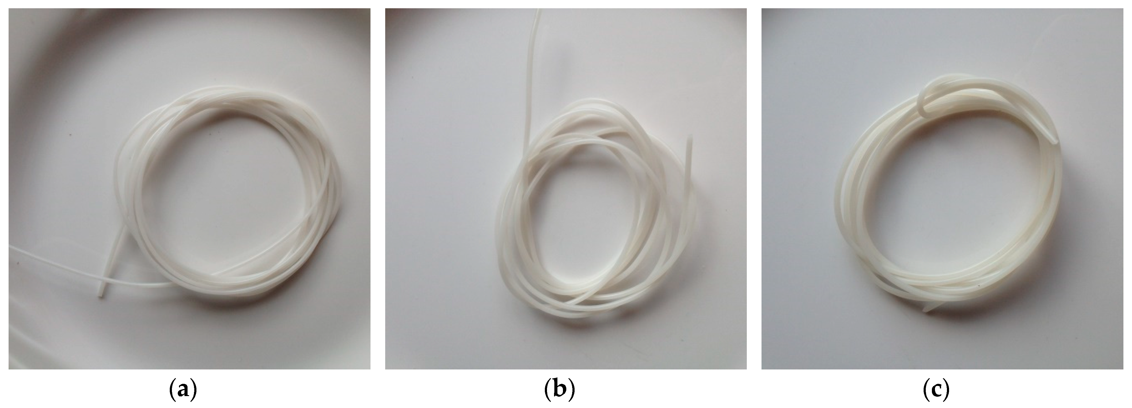
Filament which could be used as feedstock in the FFF process was produced as a result of utilization of hot melt extrusion technology. The most commonly used filaments in the FFF printing process are known to have diameters of either 1.75 mm or 3.00 mm [38,39] and the materials and production processes used in the work were observed to have the capabilities of producing a filament of diameter 1.75 ± 0.05 mm, Figure 1.
Filament diameter is one of the most crucial parameters for successful 3D printing and this may be influenced by a variety of variables such as screw speed, speed of conveyer/haul-off system, fill level of the extruder/hopper and the back pressure of the extruder [40]. Initial trials utilizing gravity alone to shape the filament post extrusion were not deemed reproducible enough to existing best practices, therefore, a custom Teflon coated conveyer belt system was used to remove die swell phenomena and attain a reproducible filament diameter. By changing the speed of the belt, adjustments to the diameter and ovality of the produced filament could be easily attained. Further studies will be conducted on the produced filaments from this work.
3.3. Colorimetry
Colorimetry was conducted on Blend 4A and Blend 4B to ascertain if the inclusion of HNTs imparted any significant change in color of the blends and also to further verify that HNTs had been dispersed throughout the polymeric matrix. Table 4 represents the colorimetric data which was recorded for each of the samples analyzed and it is apparent that the majority of the changes are occurring in the Hunter b value which is the color coordinate between blue (−100) and yellow (+100). The most noticeable change was observed for Blend 4B which obtained a Hunter b value of 7.81 when compared to that of the control sample, Blend 4, where a value of 0.89 was attained. Also, as can be observed the ΔE value (overall change) was calculated from collectively taking the changes for Hunter L, Hunter a and Hunter b into consideration and from this it can be concluded that out of the two samples, Blend 4A and Blend 4B, that Blend 4A illustrates the better optical properties of the two. This is to be expected owing to the aforementioned sample have a ΔE value, 3.06, closer to that of the control, Blend 4, and it also only contains two weight percent of the nanoclay, HNTs. Furthermore, as Blend 4B has a higher ΔE value it can be said that the higher loadings of HNTs, six weight percent, have a significant influence on the color of the sample.
3.4. Melt Flow Index
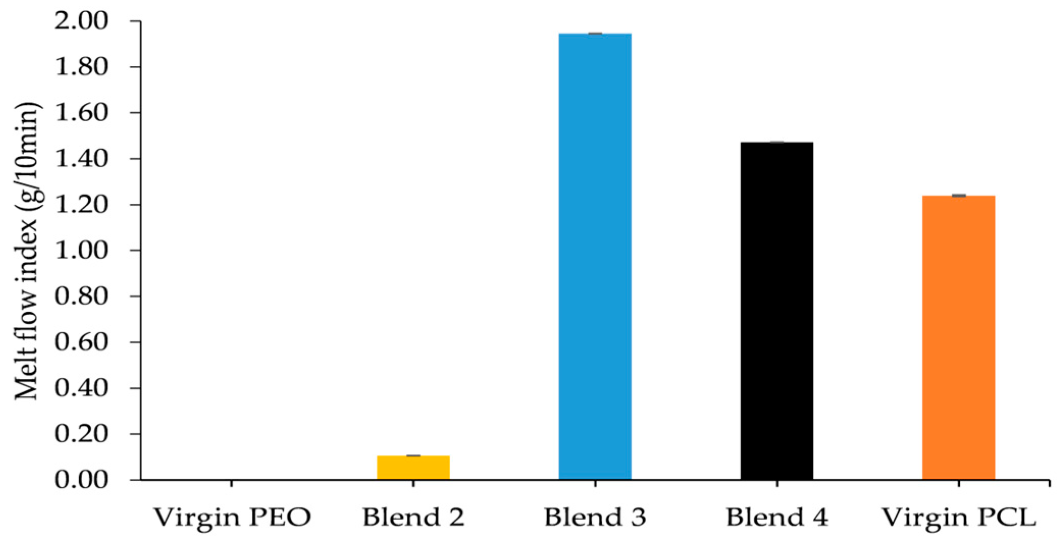
The melt flow index results obtained for the monolithic batches are presented in Figure 2. As can be observed, there is no result displayed for Virgin PEO which is due to it being highly viscous with no extrudates being produced using the prescribed test conditions. The high melt viscosity of PEO is well documented in literature with Kenny et al. [24] reporting a melt flow index of 0.72 (g/10min) for PEO with an average molecular weight of 100,000. The melt viscosity of a polymer increases with increasing molecular weight and the PEO which was used in this study had a molecular weight three times that of the PEO studied by Kenny and researchers. The incorporation of PCL was found to significantly reduce the melt viscosity of the matrix, thus indicating that PCL provides a plasticizing effect which is to be expected owing to the low melt viscosity of the Virgin PCL in comparison to Virgin PEO. The plasticizing effect of PCL has been well documented in literature and PCL has been used as a replacement for di(2-ethylhexyl) phthalate (DEHP) in poly(vinyl) chloride (PVC) compositions intended for medical device applications [41]. Blend 3 and Blend 4 displayed a lower melt viscosity than that of Virgin PCL and this reduction in melt viscosity can be attributed to the inclusion of the lower molecular weight PCL (Mw 37,000). Blend 3 displayed the lowest melt viscosity of all the batches despite the fact it did not contain the greatest total proportion of PCL which suggests that the melt viscosity of the matrix is not only affected by the repeating unit of the constituent polymers but also their chain length. As already stated, Blend 4 was selected as being the optimum batch into which the HNTs were incorporated due to the results indicating a melt flow index of 1.47 (g/10 min) which would mean that when utilized in the printing process the flowability of the polymer melt will be low, resulting in better printability and adhesion.
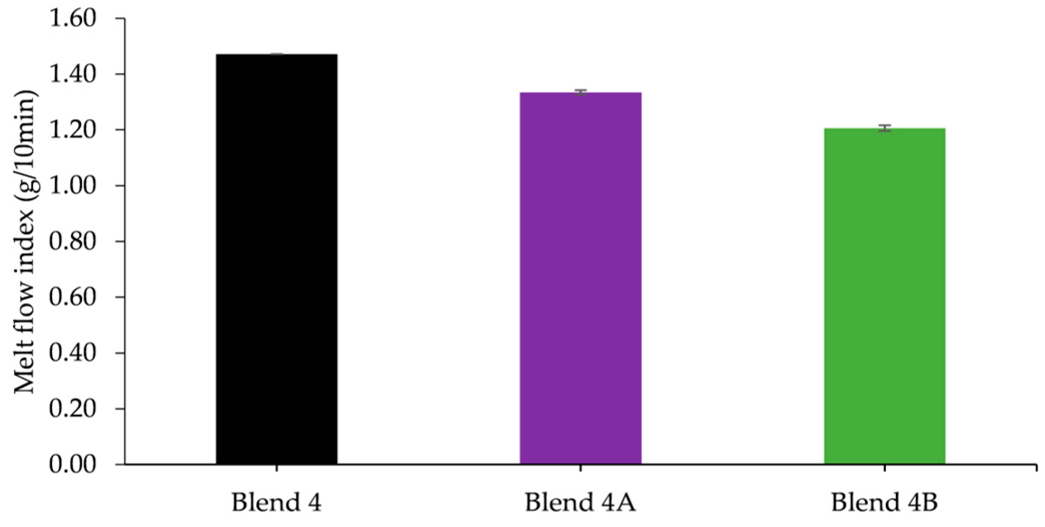
The MFI results obtained for the nanocomposite batches, Figure 3, show that the melt viscosity of Blend 4 increases with increasing HNT content. HNTs have been reported to increase the melt viscosity of polymeric matrices and in a study conducted by Kelnar and researchers [42], they concluded that HNTs have the ability to increase the viscosity of both PCL and PLA and a blend of the aforementioned two.
3.5. Mechanical Testing
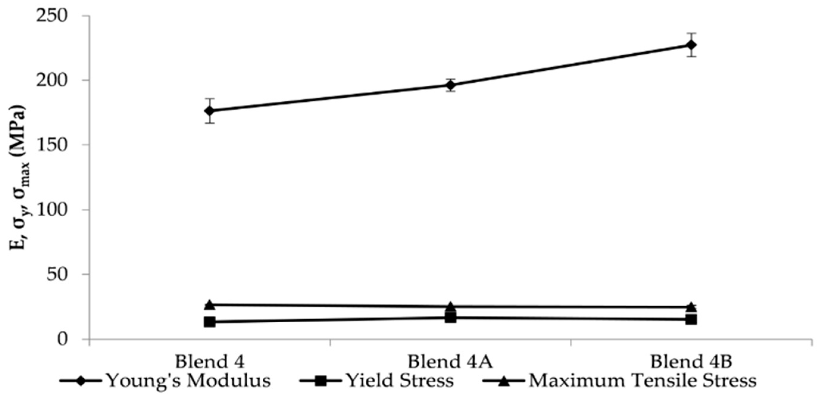
Mechanical testing and tensile testing was carried out in order to assess the short-term mechanical properties of both the prepared monolithic and nanocomposite batches with the results illustrated in Table 5 and Figure 4. The values which were obtained for both virgin polymers, PEO and PCL, are consistent with that reported in literature; however, it must be stated that there are large variations and a wide range of values reported for both of these polymers [43,44,45].
As can be observed in Table 5 Virgin PEO recorded the highest Young’s modulus of all the tested batches and it is apparent that an increased loading of PCL decreased Young’s modulus of the matrix. The Young’s modulus of Virgin PEO was found to be 327.06 MPa whereas Young’s modulus of any batches containing PCL was found to be just 192.38 ± 34.81 MPa.
The mechanical tests on the nanocomposites were undertaken in order to evaluate the effect if any, that HNTs had on the short-term mechanical properties of the PEO/PCL blend. The results in literature [46] have shown the HNTs greatly enhance the strength and stiffness of PCL matrices at a low volume fraction whilst retaining the ductility of PCL. The Young’s modulus of Blend 4 was found to increase significantly with increasing HNT content with the loadings of two and six percent providing an increase in Young’s modulus of 11% and 25% respectively. Lyons and researchers [34] conducted a study incorporating montmorillonite into a PEO matrix and noted that the increase in mechanical properties became more pronounced as the percentage of nanoclay was increased.
3.6. Differential Scanning Calorimetry
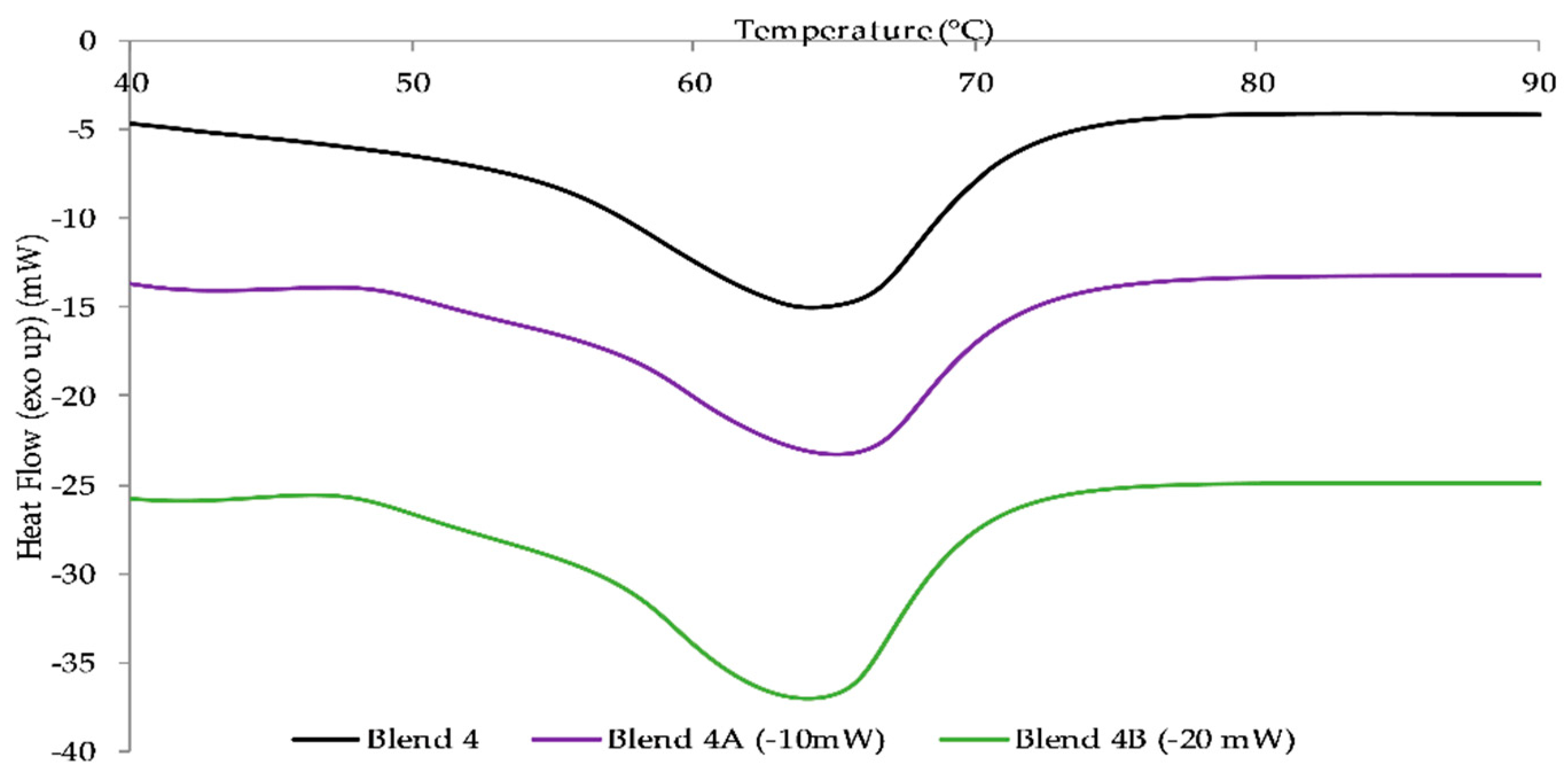
Differential scanning calorimetry of the virgin polymers and polymer blends were carried out to determine if variations in the ratios of polymer present had an effect on the thermal characteristics of the samples and also illustrate the homogeneity of the polymer blends which had been produced. Furthermore, DSC was used to ascertain if the inclusion of HNTs in the two blends, 4A and 4B, had any effect on their thermal characteristics. The DSC findings obtained for the batches presented in Table 6 with DSC thermographs displayed in Figure 5 illustrating the collated nanocomposite results.
Virgin PEO was found to have the highest melting temperature, 71.80 °C, with Virgin PCL having the lowest, 64.20 °C, of all the prepared batches with these results correlating with the values presented in literature [7,18,47,48]. Virgin PEO and Virgin PCL both exhibit their melting points as a well-defined peak as do the Blends 2–4. These well-defined peaks can be attributed to the melt compounding process that they were subjected to as the intense mixing associated with the twin screw extrusion process imparts a high mix efficiency which therefore will produce a more uniform product/extrudate [49].
The melting point of the batches decreased as the content of PCL was increased which was also observed in studies conducted by Qui and researchers [50] and Kim and co-workers [51] with the latter stating that within semi-crystalline polymeric blends it is known that the occurrence of a shift in each melting temperature in order for them to be closer together occurs when the polymeric blends are miscible. The reasoning for the shift in melt temperature towards Virgin PCL is possibly due to the increased PCL content within the other respective blends.
From the inclusion of the nanoclay filler, HNTs, it can be observed in Figure 5 that their addition, at the low loadings, had a negligible effect on the melting behavior of the Blend 4 matrix with no discernible pattern emerging. Similar observations with regard to HNTs having no adverse effects on the melting point were noted by Chen and researchers who investigated the effect HNTs had on the aliphatic polyester, polylactic acid [52]. Furthermore, in a similar study carried out by Lyons and co-workers [34] found that inclusion of the nanoclay Cloisite 93A had no effect on the melting behavior of the polymeric matrix, that being PEO.
It was found that a loading of two weight percent increased the Blend 4 matrix by 0.8 °C; however, when the loading was increased to six weight percent, the melting point reduced to a temperature that is comparable to that of Blend 4, with Prashantha and researchers [53] reporting that HNTs have little effect on the melt behavior of polymeric matrices.
4. Conclusions
The work which has been described in this research paper outlines the possibility of developing a degradable nanocomposite which could further be developed into a polymeric filament, suitable for use as a feedstock in the FFF process. All blends were prepared via HME and characterized by performing an array of commonly utilized polymeric testing procedures.
It was evident that the incorporation of PCL into the PEO matrix provided a plasticizing effect as rheological studies showed that the MFI of the monolithic batches increased with increasing PCL content. From conducting DSC it was apparent that increasing the content of PCL within the polymeric matrix caused a reduction in the melt temperature of the blend. Therefore, subsequently, Blend 4 was chosen as the matrix for the HNT reinforced nanocomposite material.
The two nanocomposite batches, Blend 4A and Blend 4B, were reinforced by the addition of two and six weight percent respectively in order to ascertain if the addition of the nanoclay would improve the mechanical strength. The rheological studies conducted indicated that the MFI of the nanocomposite batches increased with an increased loading of HNTs as did the yellowing of the batches with Blend 4B exhibiting a higher Hunter b value, 7.81, than the Hunter b value of Blend 4A, 3.94. Upon conducting tensile tests, the results obtained illustrated that the addition of HNTs significantly increased Young’s modulus of Blend 4 with an increase of 11% and 25% when the loading was two and six weight percent respectively. In addition to this it was apparent from DSC studies that the addition of HNTs had a negligible effect on the melt temperature of the polymeric matrix.
Furthermore, from conducting the study it was possible to produce a filament with a suitable diameter, 1.75 ± 0.05 mm, which could be utilized as a feedstock in the FFF process. Subsequent studies will examine the performance and characteristics of the manufactured filaments.
Author Contributions
J.G.L. conceived and designed the experiments; A.V.H. and C.W. conducted the experiments; A.V.H., C.W. and J.G.L. analyzed the data; L.M.G., D.M.D. and J.G.L. contributed materials, equipment and analysis tools; A.V.H., C.W. and J.G.L. wrote the paper.
Acknowledgments
All funding for this work was obtained from the AIT President’s Seed Fund, Athlone, Co., Westmeath, Ireland.
Conflicts of Interest
The authors declare no conflict of interest.
Appendix A

Table A1.
Injection Molding Parameters Used in the Study.
| Holding Pressure (bar) | |||||||||||||||
|---|---|---|---|---|---|---|---|---|---|---|---|---|---|---|---|
| Batch Name | Zone Temperatures (°C) | Base Point 1 | Base Point 2 | Base Point 3 | |||||||||||
| 1 | 2 | 3 | 4 | 5 | Mold | Injection Pressure (bar) | Holding Pressure (bar) | Duration (s) | Holding Pressure (bar) | Duration (s) | Holding Pressure (bar) | Duration (s) | Back Pressure (bar) | Cooling Time (s) | |
| Virgin PEO | 110 | 120 | 130 | 140 | 150 | 32 | 1100 | 900 | 8 | 850 | 3 | 800 | 0 | 50 | 50 |
| Blend 2 | 60 | 70 | 80 | 90 | 100 | 29 | 1000 | 700 | 8 | 650 | 3 | 620 | 0 | 6 | 50 |
| Blend 3 | 45 | 55 | 70 | 75 | 85 | 25 | 750 | 470 | 8 | 410 | 5 | 370 | 0 | 1 | 60 |
| Blend 4 | 60 | 60 | 70 | 80 | 90 | 20 | 1000 | 680 | 7 | 630 | 4 | 580 | 0 | 20 | 70 |
| Blend 4A | 60 | 60 | 70 | 80 | 90 | 20 | 1000 | 680 | 7 | 630 | 4 | 580 | 0 | 20 | 65 |
| Blend 4B | 60 | 60 | 70 | 80 | 90 | 20 | 1000 | 680 | 7 | 630 | 4 | 580 | 0 | 20 | 60 |
| Virgin PCL | 70 | 80 | 90 | 100 | 110 | 20 | 820 | 680 | 10 | 620 | 4 | 540 | 0 | 2 | 120 |
References
- Silverman, T.; Naffakh, M.; Marco, C.; Ellis, G. Morphology and thermal properties of biodegradable poly (hydroxybutyrate-co-hydroxyvalerate)/tungsten disulphide inorganic nanotube nanocomposites. Mater. Chem. Phys. 2016, 170, 145–153. [Google Scholar] [CrossRef]
- Bordes, P.; Pollet, E.; Avérous, L. Nano-biocomposites: Biodegradable polyester/nanoclay systems. Prog. Polym. Sci. 2009, 34, 125–155. [Google Scholar] [CrossRef]
- Hillmyer, M.A.; Tolman, W.B. Aliphatic Polyester Block Polymers: Renewable, Degradable, and Sustainable. Acc. Chem. Res. 2014, 47, 2390–2396. [Google Scholar] [CrossRef] [PubMed]
- McDonald, P.F.; Lyons, J.G.; Geever, L.M.; Higginbotham, C.L. In vitro degradation and drug release from polymer blends based on poly(dl-lactide), poly(l-lactide-glycolide) and poly(ε-caprolactone). J. Mater. Sci. 2010, 45, 1284–1292. [Google Scholar] [CrossRef]
- Chávez-Montes, W.M.; González-sánchez, G.; López-martínez, E.I.; De Lira-gómez, P.; Ballinas-casarrubias, L.; Flores-Gallardo, S. Effect of Artificial Weathering on PLA/Nanocomposite Molecular Weight Distribution. Polymers 2015, 7, 760–776. [Google Scholar] [CrossRef]
- Azimi, B.; Nourpanah, P.; Rabiee, M.; Arbab, S. Poly (ε-caprolactone) Fiber: An Overview. J. Eng. Fibers Fabr. 2014, 9, 74–90. [Google Scholar]
- Woodruff, M.A.; Hutmacher, D.W. The return of a forgotten polymer—Polycaprolactone in the 21st century. Prog. Polym. Sci. 2010, 35, 1217–1256. [Google Scholar] [CrossRef] [Green Version]
- Sinha, V.R.; Bansal, K.; Kaushik, R.; Kumria, R.; Trehan, A. Poly-ε-caprolactone microspheres and nanospheres: An overview. Int. J. Pharm. 2004, 278, 1–23. [Google Scholar] [CrossRef] [PubMed]
- Middleton, J.C.; Tipton, A.J. Synthetic biodegradable polymers as orthopedic devices. Biomaterials 2000, 21, 2335–2346. [Google Scholar] [CrossRef]
- Abedalwafa, M.; Wang, F.; Wang, L.; Li, C. Biodegradable Poly-Epsilon-Caprolactone (PCL) For Tissue Engineering Applications: A Review. Rev. Adv. Mater. Sci. 2013, 34, 123–140. [Google Scholar]
- Cipitria, A.; Skelton, A.; Dargaville, T.R.; Dalton, P.D.; Hutmacher, D.W. Design, fabrication and characterization of PCL electrospun scaffolds—A review. J. Mater. Chem. 2011, 21, 9419. [Google Scholar] [CrossRef] [Green Version]
- Hassan, Z.M.; Goyanes, A.; Clark, V.; Basit, A.W.; Hilton, S.T.; Gaisford, S. Patient-Specific 3D Scanned and 3D Printed Antimicrobial Polycaprolactone Wound Dressings. Int. J. Pharm. 2017. [Google Scholar] [CrossRef]
- Fuenmayor, E.; Forde, M.; Healy, A.; Devine, D.; Lyons, J.; McConville, C.; Major, I. Material Considerations for Fused-Filament Fabrication of Solid Dosage Forms. Pharmaceutics 2018, 10, 44. [Google Scholar] [CrossRef] [PubMed]
- Patrício, T.; Glória, A.; Bártolo, P. Mechanical and biological behaviour of PCL and PCL/PLA scaffolds for tissue engineering applications. Chem. Eng. Trans. 2013, 32, 1645–1650. [Google Scholar] [CrossRef]
- Patrício, T.; Domingos, M.; Gloria, A.; Bártolo, P. Characterisation of PCL and PCL/PLA Scaffolds for Tissue Engineering. Procedia CIRP 2013, 5, 110–114. [Google Scholar] [CrossRef]
- Patrício, T.; Domingos, M.; Gloria, A.; D’Amora, U.; Coelho, J.F.; Bártolo, P.J. Fabrication and characterisation of PCL and PCL/PLA scaffolds for tissue engineering. Rapid Prototyp. J. 2014, 20, 145–156. [Google Scholar] [CrossRef]
- Borzacchiello, A.; Gloria, A.; Mayol, L.; Dickinson, S.; Miot, S.; Martin, I.; Ambrosio, L. Natural/synthetic porous scaffold designs and properties for fibro-cartilaginous tissue engineering. J. Bioact. Compat. Polym. 2011, 26, 437–451. [Google Scholar] [CrossRef]
- Crowley, M.M.; Zhang, F.; Koleng, J.J.; McGinity, J.W. Stability of polyethylene oxide in matrix tablets prepared by hot-melt extrusion. Biomaterials 2002, 23, 4241–4248. [Google Scholar] [CrossRef]
- Spietelun, A.; Pilarczyk, M.; Kloskowski, A.; Namieśnik, J. Polyethylene glycol-coated solid-phase microextraction fibres for the extraction of polar analytes—A review. Talanta 2011, 87, 1–7. [Google Scholar] [CrossRef] [PubMed]
- Kojima, H.; Yoshihara, K.; Sawada, T.; Kondo, H.; Sako, K. Extended release of a large amount of highly water-soluble diltiazem hydrochloride by utilizing counter polymer in polyethylene oxides (PEO)/polyethylene glycol (PEG) matrix tablets. Eur. J. Pharm. Biopharm. 2008, 70, 556–562. [Google Scholar] [CrossRef] [PubMed]
- Park, S.-J.; Kim, K.-S.; Kim, S.-H. Effect of poly(ethylene oxide) on the release behaviors of poly(ε-caprolactone) microcapsules containing erythromycin. Colloids Surf. B Biointerfaces 2005, 43, 238–244. [Google Scholar] [CrossRef] [PubMed]
- Lyons, J.G.; Devine, D.M.; Kennedy, J.E.; Geever, L.M.; O’Sullivan, P.; Higginbotham, C.L. The use of agar as a novel filler for monolithic matrices produced using hot melt extrusion. Eur. J. Pharm. Biopharm. 2006, 64, 75–81. [Google Scholar] [CrossRef] [PubMed]
- Zhang, F.; McGinity, J.W. Properties of sustained-release tablets prepared by hot-melt extrusion. Pharm. Dev. Technol. 1999, 4, 241–250. [Google Scholar] [CrossRef] [PubMed]
- Kenny, E.; Devine, D.; Higginbotham, C.; Geever, L. Processing and Characterisation of Various Polymer Blends to Develop Implant for Tissue Engineering Applications. J. Asian Sci. Res. 2013, 3, 654–669. [Google Scholar]
- Grehan, L.; Killion, J.A.; Devine, D.M.; Kenny, E.K.; Devery, S.; Higginbotham, C.L.; Geever, L.M. The Development of Hot Melt Extruded Biocompatible Controlled Release Drug Delivery Devices. Int. J. Polym. Mater. Polym. Biomater. 2014, 63, 476–485. [Google Scholar] [CrossRef]
- Liu, M.; Jia, Z.; Jia, D.; Zhou, C. Recent advance in research on halloysite nanotubes-polymer nanocomposite. Prog. Polym. Sci. 2014, 39, 1498–1525. [Google Scholar] [CrossRef]
- Chang, J.H.; An, Y.U.; Cho, D.; Giannelis, E.P. Poly(lactic acid) nanocomposites: Comparison of their properties with montmorillonite and synthetic mica (II). Polymer 2003, 44, 3715–3720. [Google Scholar] [CrossRef]
- Sinha Ray, S.; Yamada, K.; Okamoto, M.; Ogami, A.; Ueda, K. New polylactide/layered silicate nanocomposites. 3. High-performance biodegradable materials. Chem. Mater. 2003, 15, 1456–1465. [Google Scholar] [CrossRef]
- Tzounis, L.; Herlekar, S.; Tzounis, A.; Charisiou, N.D.; Goula, M.; Stamm, M. Halloysite Nanotubes Noncovalently Functionalised with SDS Anionic Surfactant and PS-b-P4VP Block Copolymer for Their Effective Dispersion in Polystyrene as UV-Blocking Nanocomposite Films. J. Nanomater. 2017, 2017, 3852310. [Google Scholar] [CrossRef] [PubMed]
- Kenny, E.K.; Gately, N.M.; Killion, J.A.; Devine, D.M.; Higginbotham, C.L.; Geever, L.M. Melt Extruded Bioresorbable Polymer Composites for Potential Regenerative Medicine Applications. Polym. Plast. Technol. Eng. 2016, 55, 432–446. [Google Scholar] [CrossRef]
- Patel, S.; Jammalamadaka, U.; Sun, L.; Tappa, K.; Mills, D. Sustained Release of Antibacterial Agents from Doped Halloysite Nanotubes. Bioengineering 2015, 3, 1. [Google Scholar] [CrossRef] [PubMed]
- Breitenbach, J. Melt extrusion: From process to drug delivery technology. Eur. J. Pharm. Biopharm. 2002, 54, 107–117. [Google Scholar] [CrossRef]
- Stanković, M.; Frijlink, H.W.; Hinrichs, W.L.J. Polymeric formulations for drug release prepared by hot melt extrusion: Application and characterization. Drug Discov. Today 2015, 20, 812–823. [Google Scholar] [CrossRef] [PubMed]
- Lyons, J.G.; Holehonnur, H.; Devine, D.M.; Kennedy, J.E.; Geever, L.M.; Blackie, P.; Higginbotham, C.L. The incorporation of an organically modified layered silicate in monolithic polymeric matrices produced using hot melt extrusion. Mater. Chem. Phys. 2007, 103, 419–426. [Google Scholar] [CrossRef]
- Lyons, J.G.; Blackie, P.; Higginbotham, C.L. The significance of variation in extrusion speeds and temperatures on a PEO/PCL blend based matrix for oral drug delivery. Int. J. Pharm. 2008, 351, 201–208. [Google Scholar] [CrossRef] [PubMed]
- Lyons, J.G.; Hallinan, M.; Kennedy, J.E.; Devine, D.M.; Geever, L.M.; Blackie, P.; Higginbotham, C.L. Preparation of monolithic matrices for oral drug delivery using a supercritical fluid assisted hot melt extrusion process. Int. J. Pharm. 2007, 329, 62–71. [Google Scholar] [CrossRef] [PubMed]
- Prashantha, K.; Lacrampe, M.-F.; Krawczak, P. Halloysite Nanotubes-Polymer Nano composites:A New Class of Multifaceted Materials. Adv. Mater. Manuf. Charact. 2013, 3, 11–14. [Google Scholar] [CrossRef]
- Goyanes, A.; Robles Martinez, P.; Buanz, A.; Basit, A.W.; Gaisford, S. Effect of geometry on drug release from 3D printed tablets. Int. J. Pharm. 2015, 494, 657–663. [Google Scholar] [CrossRef] [PubMed]
- Ligon, S.C.; Liska, R.; Stampfl, J.; Gurr, M.; Mülhaupt, R. Polymers for 3D Printing and Customized Additive Manufacturing. Chem. Rev. 2017, 117, 10212–10290. [Google Scholar] [CrossRef] [PubMed]
- Holländer, J.; Genina, N.; Jukarainen, H.; Khajeheian, M.; Rosling, A.; Mäkilä, E.; Sandler, N. Three-Dimensional Printed PCL-Based Implantable Prototypes of Medical Devices for Controlled Drug Delivery. J. Pharm. Sci. 2016, 105, 2665–2676. [Google Scholar] [CrossRef] [PubMed]
- Rusu, M.; Ursu, M.; Rusu, D. Poly(vinyl chloride) and Poly(ε-caprolactone) Blends for Medical Use. J. Thermoplast. Compos. Mater. 2006, 19, 173–190. [Google Scholar] [CrossRef]
- Kelnar, I.; Kratochvíl, J.; Fortelný, I.; Kaprálková, L.; Zhigunov, A.; Khunová, V.; Nevoralová, M. Effect of halloysite on structure and properties of melt-drawn PCL/PLA microfibrillar composites. Express Polym. Lett. 2016, 10, 381–393. [Google Scholar] [CrossRef]
- Eshraghi, S.; Das, S. Mechanical and microstructural properties of polycaprolactone scaffolds with one-dimensional, two-dimensional, and three-dimensional orthogonally oriented porous architectures produced by selective laser sintering. Acta Biomater. 2010, 6, 2467–2476. [Google Scholar] [CrossRef] [PubMed]
- Saeed, K.; Ishaq, M.; Ilyas, M. Preparation, morphology, and thermomechanical properties of coal ash/polyethylene oxide composites. Turk. J. Chem. 2011, 35, 237–243. [Google Scholar] [CrossRef]
- Zaman, H.U.; Beg, M.D.H. Improvement of physico-mechanical, thermomechanical, thermal and degradation properties of PCL/gelatin biocomposites: Effect of gamma radiation. Radiat. Phys. Chem. 2015, 109, 73–82. [Google Scholar] [CrossRef]
- Lee, K.-S.; Chang, Y.-W. Thermal, mechanical, and rheological properties of poly(ε-caprolactone)/halloysite nanotube nanocomposites. J. Appl. Polym. Sci. 2013, 128, 2807–2816. [Google Scholar] [CrossRef]
- Maggi, L.; Bruni, R.; Conte, U. High molecular weight polyethylene oxides (PEOs) as an alternative to HPMC in controlled release dosage forms. Int. J. Pharm. 2000, 195, 229–238. [Google Scholar] [CrossRef]
- Labet, M.; Thielemans, W. Synthesis of polycaprolactone: A review. Chem. Soc. Rev. 2009, 38, 3484–3504. [Google Scholar] [CrossRef] [PubMed]
- Martin, C. Twin Screw Extruders as Continuous Mixers for Thermal Processing: A Technical and Historical Perspective. AAPS PharmSciTech 2016, 17, 3–19. [Google Scholar] [CrossRef] [PubMed]
- Qiu, Z.; Ikehara, T.; Nishi, T. Miscibility and crystallization of poly(ethylene oxide) and poly(ε-caprolactone) blends. Polymer 2003, 44, 3101–3106. [Google Scholar] [CrossRef]
- Kim, T.G.; Lee, D.S.; Park, T.G. Controlled protein release from electrospun biodegradable fiber mesh composed of poly(ɛ-caprolactone) and poly(ethylene oxide). Int. J. Pharm. 2007, 338, 276–283. [Google Scholar] [CrossRef] [PubMed]
- Chen, Y.; Geever, L.M.; Killion, J.A.; Lyons, J.G.; Higginbotham, C.L.; Devine, D.M. Halloysite nanotube reinforced polylactic acid composite. Polym. Compos. 2015, 16. [Google Scholar] [CrossRef]
- Prashantha, K.; Lacrampe, M.F.; Krawczak, P. Processing and characterization of halloysite nanotubes filled polypropylene nanocomposites based on a masterbatch route: Effect of halloysites treatment on structural and mechanical properties. Express Polym. Lett. 2011, 5, 295–307. [Google Scholar] [CrossRef]
Figure 1.
Filaments produced by hot melt extrusion (HME) (a) Blend 4; (b) Blend 4A and (c) Blend 4B.
Figure 1.
Filaments produced by hot melt extrusion (HME) (a) Blend 4; (b) Blend 4A and (c) Blend 4B.

Figure 2.
Melt flow index results of monolithic batches.

Figure 3.
Melt flow index results of nanocomposite batches.

Figure 4.
Selected mechanical data for the batches under investigation where, E represents Young’s modulus, σy is the yield stress and σmax is the maximum tensile stress (n = 5).
Figure 4.
Selected mechanical data for the batches under investigation where, E represents Young’s modulus, σy is the yield stress and σmax is the maximum tensile stress (n = 5).

Figure 5.
Overlaid differential scanning calorimetry (DSC) thermographs of Blend 4 and the two nanocomposite batches, Blend 4A and Blend 4B.
Figure 5.
Overlaid differential scanning calorimetry (DSC) thermographs of Blend 4 and the two nanocomposite batches, Blend 4A and Blend 4B.

Table 1.
Batch compositions prepared. PEO: Poly(ethylene oxide); PCL: Poly(ε-caprolactone); HNTs: Halloysite nanotubes.
Table 1.
Batch compositions prepared. PEO: Poly(ethylene oxide); PCL: Poly(ε-caprolactone); HNTs: Halloysite nanotubes.
| Batch Name | PEO Mw 300,000 | PCL Mw 80,000 | PCL Mw 37,000 | HNTs |
|---|---|---|---|---|
| Weight % | ||||
| Virgin PEO | 100.00 | - | - | - |
| Blend 2 | 75.00 | 12.50 | 12.50 | - |
| Blend 3 | 33.33 | 33.33 | 33.33 | - |
| Blend 4 | 12.50 | 75.00 | 12.50 | - |
| Virgin PCL | - | 100.00 | - | - |
| Blend 4A | 12.25 | 73.50 | 12.25 | 2.00 |
| Blend 4B | 11.75 | 70.50 | 11.75 | 6.00 |
| Masterbatch A | 85.96 | - | - | 14.04 |
| Masterbatch B | 66.20 | - | - | 33.80 |
Table 2.
Extrusion conditions of APV.
| Batch Name | Temperature (°C) | ||||||
|---|---|---|---|---|---|---|---|
| Zone 1 | Zone 2 | Zone 3 | Zone 4 | Zone 5 | Zone 6 | Die | |
| Virgin PEO | 90 | 100 | 110 | 120 | 130 | 140 | 140 |
| Blend 2 | 80 | 90 | 100 | 110 | 120 | 130 | 130 |
| Blend 3 | 60 | 70 | 80 | 90 | 100 | 110 | 110 |
| Blend 4 | 50 | 60 | 70 | 80 | 90 | 100 | 100 |
| Virgin PCL | 50 | 60 | 70 | 80 | 90 | 100 | 100 |
| Blend 4A | 50 | 60 | 70 | 80 | 90 | 100 | 100 |
| Blend 4B | 50 | 60 | 70 | 80 | 90 | 100 | 100 |
Table 3.
Extrusion conditions of Leistritz.
| Screw Speed (RPM) | Temperature (°C) | |||||||||
|---|---|---|---|---|---|---|---|---|---|---|
| Zone 1 | Zone 2 | Zone 3 | Zone 4 | Zone 5 | Zone 6 | Zone 7 | Zone 8 | Zone 9 | Die | |
| 170 | 80 | 90 | 100 | 110 | 120 | 125 | 130 | 135 | 140 | 140 |
Table 4.
Colorimetric data obtained for selected batches.
| Batch Name | L | a | b | ΔE |
|---|---|---|---|---|
| Blend 4 | 78.11 | −0.65 | 0.89 | 0.00 |
| Blend 4A | 77.90 | −0.67 | 3.94 | 3.06 |
| Blend 4B | 74.81 | −1.04 | 7.81 | 7.68 |
Table 5.
Mechanical testing results of prepared batches.
| Batch Name | Young’s Modulus (E) | Yield Stress (σy) | Maximum Tensile Stress (σmax) |
|---|---|---|---|
| MPa | |||
| Virgin PEO | 327.06 ± 26.84 | 13.61 ± 0.08 | 17.71 ± 0.56 |
| Blend 2 | 207.87 ± 17.49 | 13.41 ± 0.11 | 18.20 ± 0.56 |
| Blend 3 | 215.11 ± 9.37 | 14.00 ± 0.26 | 28.34 ± 1.53 |
| Blend 4 | 176.31 ± 9.37 | 13.33 ± 0.06 | 26.64 ± 0.44 |
| Blend 4A | 196.15 ± 4.80 | 16.56 ± 0.44 | 25.20 ± 0.45 |
| Blend 4B | 277.19 ± 8.90 | 15.22 ± 0.74 | 24.85 ± 1.20 |
| Virgin PCL | 192.38 ± 6.82 | 13.77 ± 0.18 | 32.07 ± 0.42 |
Table 6.
Differential scanning calorimetry (DSC) results of monolithic and nanocomposite batches.
| Batch Name | Melt Peak Temperature (°C) |
|---|---|
| Virgin PEO | 71.80 |
| Blend 2 | 69.90 |
| Blend 3 | 66.20 |
| Blend 4 | 64.20 |
| Blend 4A | 65.00 |
| Blend 4B | 64.00 |
| Virgin PCL | 64.20 |
© 2018 by the authors. Licensee MDPI, Basel, Switzerland. This article is an open access article distributed under the terms and conditions of the Creative Commons Attribution (CC BY) license (http://creativecommons.org/licenses/by/4.0/).
Share and Cite
MDPI and ACS Style
Healy, A.V.; Waldron, C.; Geever, L.M.; Devine, D.M.; Lyons, J.G. Degradable Nanocomposites for Fused Filament Fabrication Applications. J. Manuf. Mater. Process. 2018, 2, 29. https://doi.org/10.3390/jmmp2020029
AMA Style
Healy AV, Waldron C, Geever LM, Devine DM, Lyons JG. Degradable Nanocomposites for Fused Filament Fabrication Applications. Journal of Manufacturing and Materials Processing. 2018; 2(2):29. https://doi.org/10.3390/jmmp2020029
Chicago/Turabian StyleHealy, Andrew V., Cathal Waldron, Luke M. Geever, Declan M. Devine, and John G. Lyons. 2018. "Degradable Nanocomposites for Fused Filament Fabrication Applications" Journal of Manufacturing and Materials Processing 2, no. 2: 29. https://doi.org/10.3390/jmmp2020029