Influence of NC Program Quality and Geometric Errors of Rotary Axes on S-Shaped Machining Test Accuracy

1
Department of Mechanical Engineering, Kobe University, 1-1 Rokko-dai, Nada, Kobe 657-8501, Japan
2
Department of Mechanical Engineering, Osaka Institute of Technology, 5-16-1 Omiya, Asahi, Osaka 535-8585, Japan
*
Author to whom correspondence should be addressed.
J. Manuf. Mater. Process. 2018, 2(2), 21; https://doi.org/10.3390/jmmp2020021
Submission received: 9 February 2018
/
Revised: 14 March 2018
/
Accepted: 14 March 2018
/
Published: 21 March 2018
(This article belongs to the Special Issue Precision Manufacturing)
Abstract
:An S-shaped machining test is proposed for the ISO 10791-7 standard to verify the performance of five-axis machining centers. However, investigation of the factor that has the most influence on the geometrical accuracy of finished S-shaped workpieces has not been undertaken. Determination of the influence of NC program tolerance and geometric errors concerning the rotary axes on the accuracy of the finished S-shaped workpiece forms the main objective of the study. Actual cutting experiments as well as simulations were performed during the proposed investigation. Our results clarify that NC-program tolerance has a significant influence on the end quality of the machined surface. Although geometric errors pertaining to rotary axes also have a significant influence on machined-surface quality, it is difficult to evaluate the influence of each individual error, because all geometric errors make glitches at the same point on the machined surface. The proposed S-shaped machining test can be used to provide a complete demonstration of available machining techniques.
1. Introduction
Five-axis machining centers can control both the orientation and position of the tool with respect to the workpiece. Such machining centers are typically applied to machine intricate geometries of mechanical and aerodynamic parts such as impellers. Although the use of five-axis machining centers offers many advantages, some drawbacks do exist in their operation. Perhaps the most significant disadvantage is that the motion accuracy of five-axis machining centers is typically lower than the conventional three-axis machining centers. This is because such machining centers possess many sources of errors compared to conventional three-axis machining centers.
To improve the geometrical accuracy of machined workpieces through use of five-axis machining centers, it is important to evaluate their motion accuracy [1]. The ISO 230-1 standard [2] defines the many sources of errors and their corresponding evaluation strategies under quasi-static and no-load operating conditions. Particularly, about five-axis machining centers, it is known that position and orientation errors of the rotational centers—called geometric errors—exist in terms of the rotary axes. Because geometric errors tend to deteriorate the geometrical accuracy of machined parts, several researches have been performed to identify and compensate for these errors.
Tsutsumi and Saito [3,4] proposed methods to identify geometric errors concerning rotary axes through use of a ball–bar system. An accuracy enhancement method, based on identified results, to compensate for the geometric errors had also been proposed [5]. Bringmann and Knapp [6] proposed a method to identify geometric errors by making use of a measurement system called “R-test,” which comprises a reference sphere and displacement sensors [7]. These evaluation methods have been implemented into the ISO 10791-6 standard, Annex A to C [8]. Xiang and Altintas [9] proposed a total compensation strategy for volumetric errors including geometric errors of the rotary axes.
Evaluation of the geometrical accuracy of machined workpieces when using five-axis machining centers has also been performed. The oldest and most well-known workpiece is the cone frustum, defined in the NAS 979 standard [10]. Although cone frustum cutting tests were originally devised for testing universal-head-type machines, which comprise two rotary axes on the spindle side, it is equally applicable to other types of machines as well. The cone frustum cutting test has also been included in the ISO 10791-7 standard [11]. It is also known that ball–bar measurement of equivalent motions is possible when executing the cone frustum cutting operation [12,13]. The ball-bar measurement method is also included in the ISO 10791-6 standard, Annex A to C [8].
The S-shaped machining test has been informatively proposed for the ISO 10791-7 standard as an optional five-axis machining test [14]. The test involves simultaneous five-axis peripheral machining by means of a square-end mill, which is widely applied in five-axis machining [15,16,17]. Wang et al. [18,19] investigate the geometrical and kinematic characteristics of the S-shape, and Jiang et al. [20] analyzed machined surfaces considering the behavior of feed-drive systems. Results of these studies clarify that the dynamic response of feed-drive systems has a significant impact on machined-surface accuracy because the velocity of each axis is subject to rapidly change during motion.
On the other hand, it is reported that the machined shape is not influenced by characteristics of the machine tool exclusively. Nakai and Ihara [21] clarified that the CAD software employed to create the 3D CAD model also influences the geometrical shape of the workpiece. It is also expected that the tolerance of the NC program may influence machined-surface accuracy. However, the influence of this tolerance on machined results has not been considered part of the proposed investigation.
The purpose of this study is to investigate the error factors that influence the accuracy of the machined S-shape and surface quality, and to establish that the proposed S-shaped machining test cannot exclusively evaluate the accuracy of five-axis machine tools. To achieve this purpose, actual machining tests and corresponding simulations have been performed using two NC programs with different tolerance values. The positional and angular commands as well as feedback signals were gathered from the NC program to analyze the motion of each axis. The influence of geometric errors concerning rotary axes was investigated through simulations.
2. S-Shaped Machining Test and Simulation
Figure 1 depicts the defined S-shaped workpiece proposed as per ISO standard recommendations [14]. Both side walls of the workpiece were machined via peripheral machining techniques employing a square-end mill. The shape was defined using ruled surfaces comprising 4 spline curves with 12 control points on each curve, as depicted in Figure 2a. Figure 2b demonstrates the 3D CAD model generated based on the defined control points. Because normal vectors corresponding to the different surfaces change continuously, simultaneous five-axis motion is required to achieve the desired accuracy of peripheral milling processes.
A five-axis machining center (NMV 1500 DCG, DMG MORI), with its B- and C-axis aligned on the table side, as depicted in Figure 3a, is employed in this study. Although the size of the workpiece has been defined in this paper, machining tests in this study were performed on a reduced size model (90% of proposed dimensions) of the workpiece owing to the small stroke limit of the machining center. The workpiece is set at the center of the table in the X-Y plane and the bottom surface of the workpiece is set at a height of 30 mm from the table surface. The roughing process is also carried out in accordance with the proposed method [14]. Cutting condition for the finishing is listed in Table 1. Figure 3b depicts the actual workpiece set onto the worktable of the five-axis machining center. NC programs utilizing TCP control functions were generated using a CAM software—ESPRIT (DP Technology).
It is known that geometric errors listed in Table 2 exist and influence the accuracy of the machined workpiece [3,4,5]. Unfortunately, however, it is difficult to control the geometric errors in actual machines. In this study, therefore, a previously developed simulator [22,23] capable of predicting the influence of geometric errors on the finished surface was employed to investigate the influence of such errors.
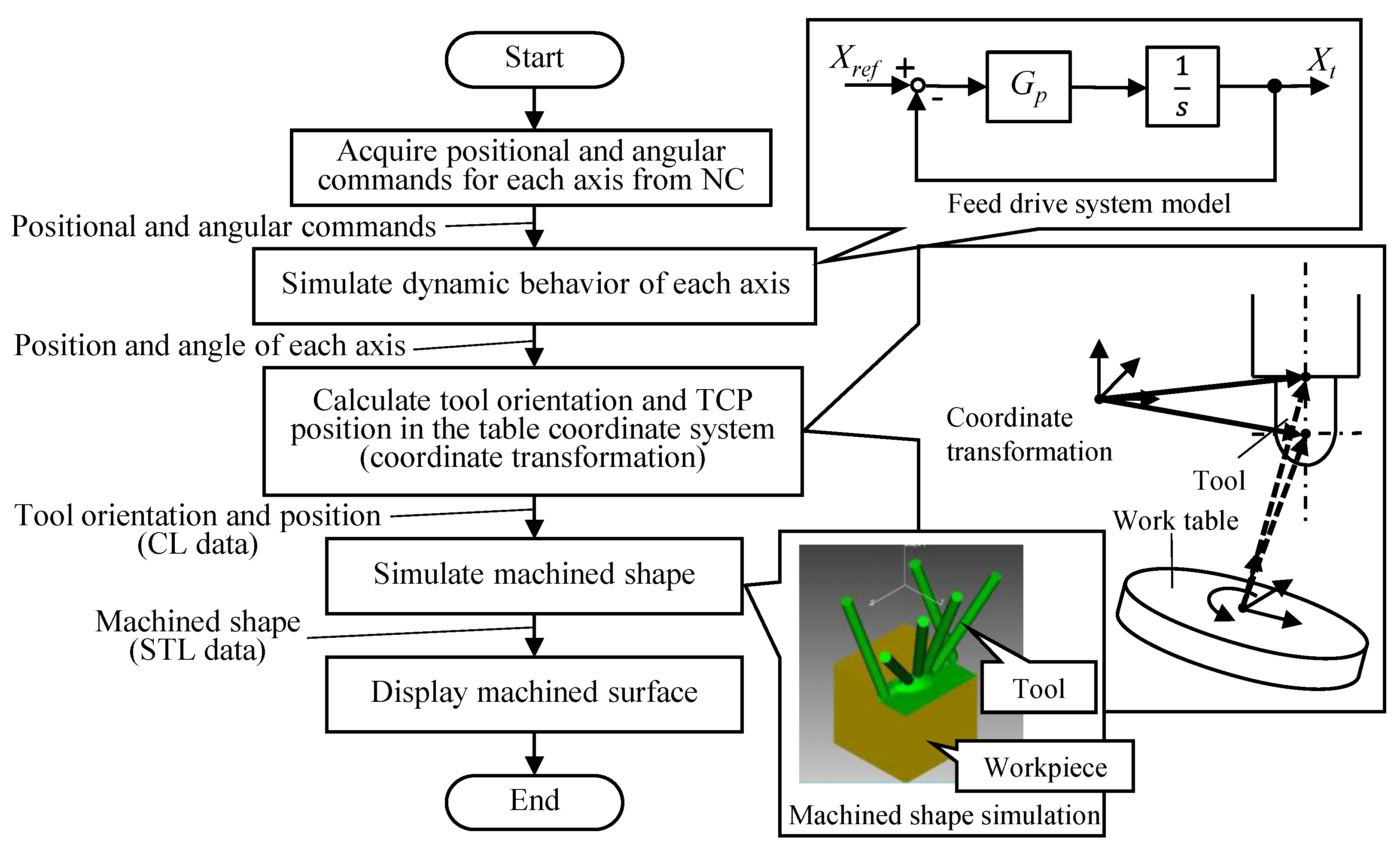
Figure 4 depicts a flowchart of the simulation method. During simulation, feedback positions and angles corresponding to each axis were acquired using a servo monitoring software (Servo Guide, FANUC, Oshino, Japan). Tool position and orientation in the table coordinate system could be predicted using coordinate transformation matrices with geometric errors. The machined shape could also be simulated using a commercial cutting simulation software—VERICUT (CG Tech), and the finished surface could be displayed using a free computer graphics software—Blender (Blender foundation).
3. Feed Motion in the S-Shaped Machining Test
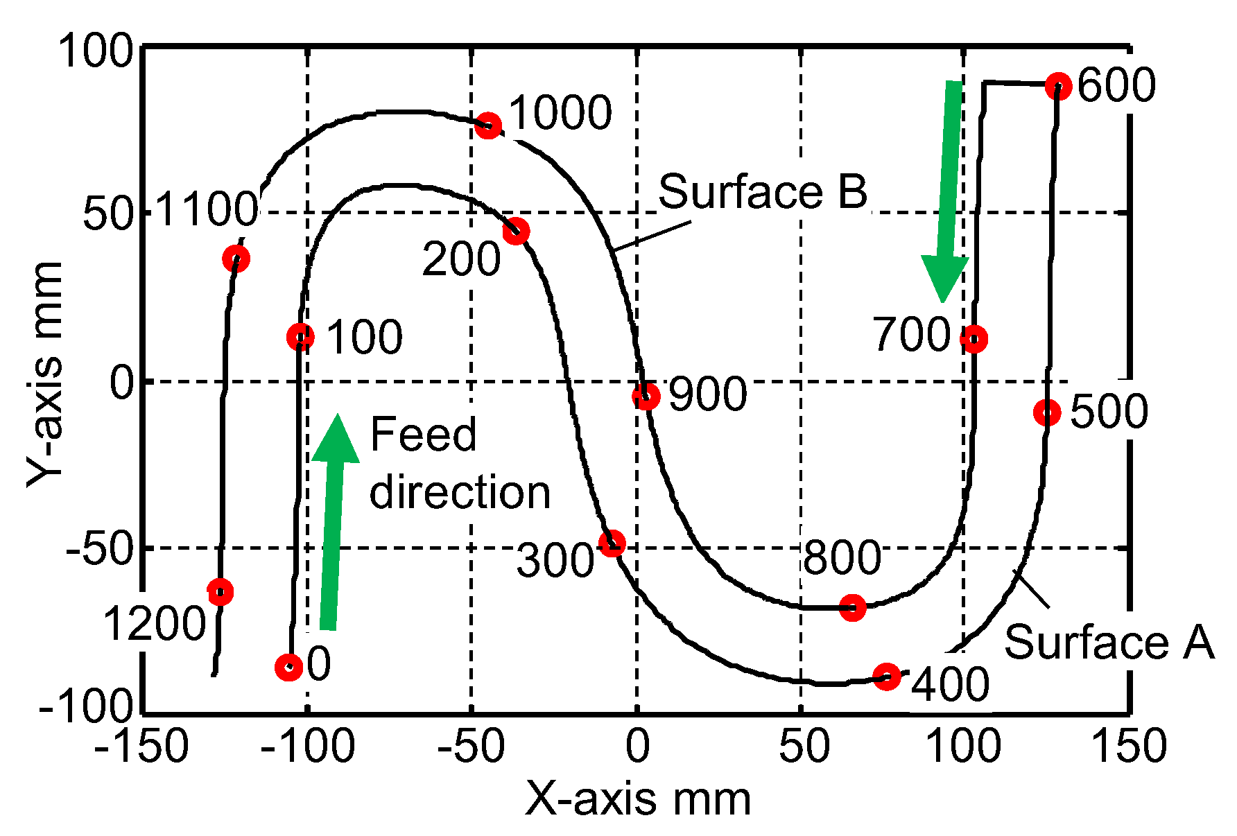
Figure 5 depicts motion trajectory of the tool center-point in the table coordinate system. As seen in the figure, tool motion starts from the lower left side of the workpiece. Numbers on the trajectory indicate tool displacement from the starting point along the motion path. The surface machined during the first half of the motion is marked as Surface A while that machined during the second half is labeled Surface B in the figure.
Figure 6 depicts the linear and angular displacements of the translational and rotational axes, respectively, during the S-shape machining process. As can be seen in the figure, all axes tend to move simultaneously. In addition, it can be seen from Figure 6b that the C-axis rotates rapidly through 90 degrees around the 250-mm mark on Surface A and 900-mm mark on Surface B.
Figure 7 depicts the tangential velocity of the tool center-point calculated from the acquired positional and angular commands pertaining to the tool axes. As can be seen from the figure, the actual feed rate fluctuates during tool motion, although the feed rate is set to 1000 mm/min. This fluctuation is mainly caused by acceleration and deceleration of the axes to avoid occurrence of mechanical vibrations. It is expected that the velocity fluctuations would, subsequently, lead to tool-bending fluctuations owing to changes in the cutting force. This, in turn, would lead to geometrical shape errors being incurred regarding machined surface precision and accuracy. In addition, these errors would not, in any way, be related to motion inaccuracies of the machining center.
4. Influence of NC Program Quality
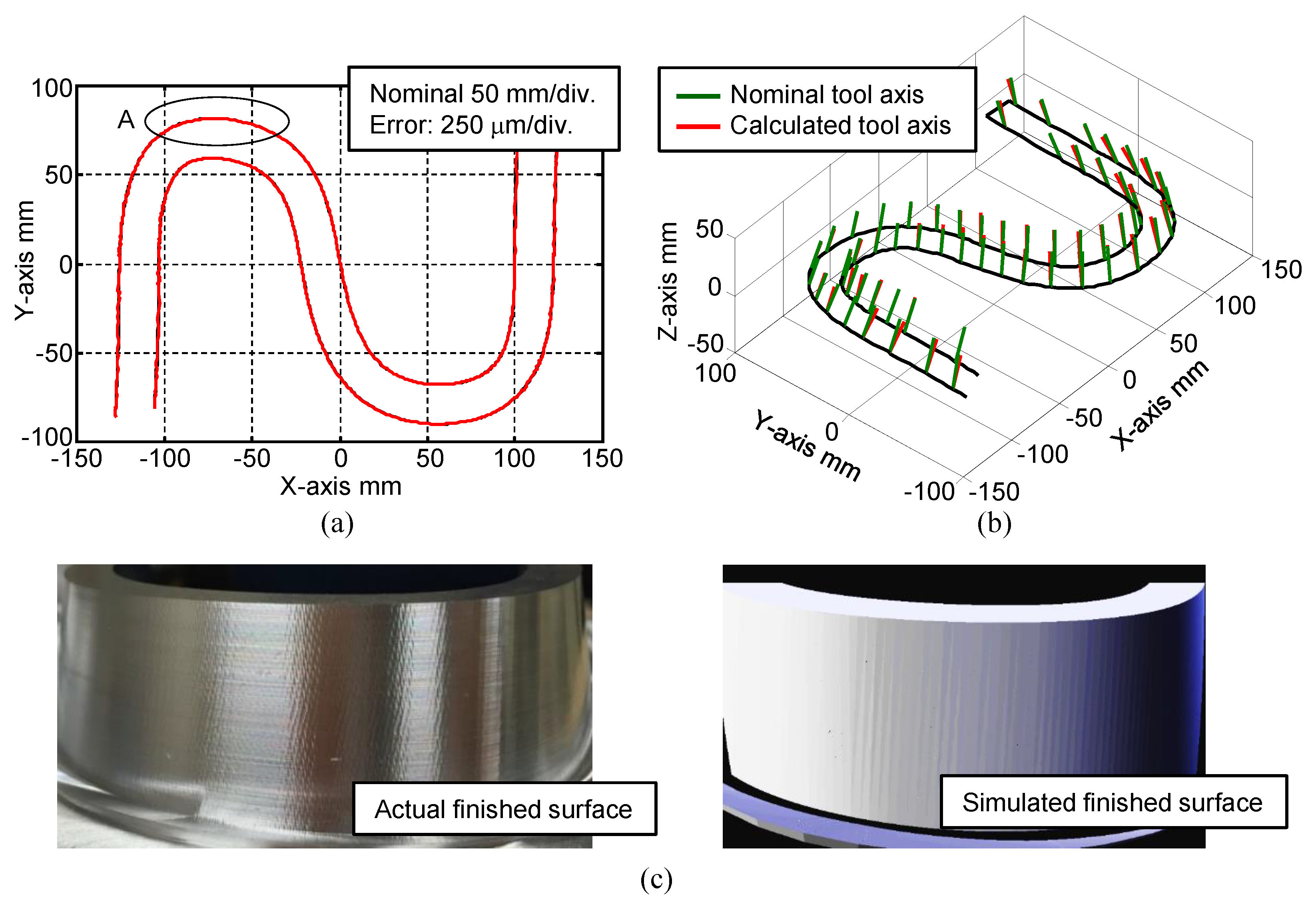
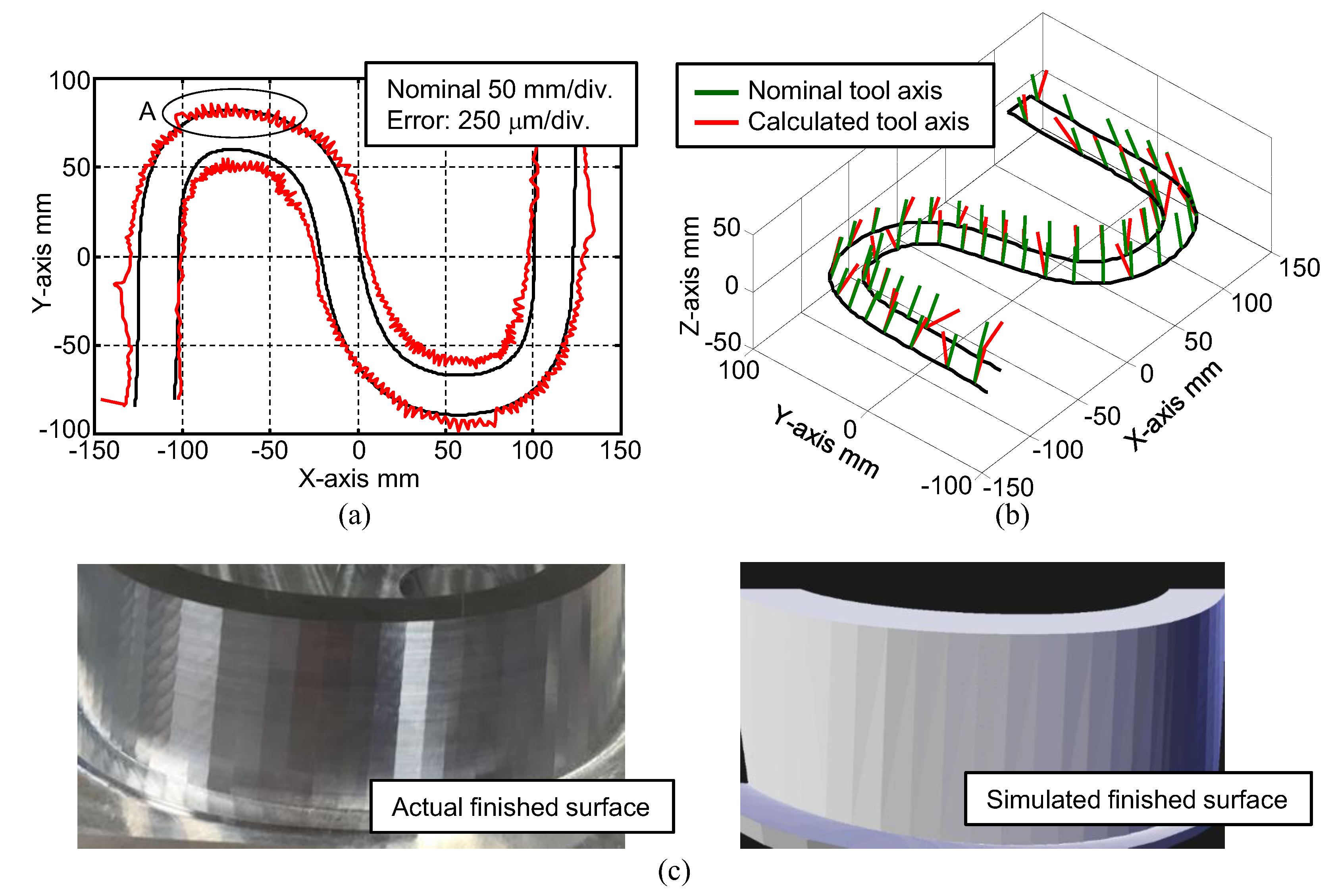
To investigate the influence of NC-program quality on machined results, actual cutting tests and simulations were performed using different NC programs with different tolerance values. Figure 8 depicts results obtained using an NC program that allows tolerance of up to 0.01 mm. Figure 9, on the other hand, depicts results obtained using an NC program, which allows tolerance of up to 0.1 mm. Tolerance setting is an important factor to be considered when generating an NC program using a CAM system, because tolerance defines the maximum chord error between the designed geometry and the geometry commanded by the NC program.
Figure 8a and Figure 9a depict motion trajectories of tool center-point, which are calculated using the acquired feedback positions and angles. The normal error between the reference and calculated paths was magnified 200 times for visualization. Although no significant motion error could be observed in the 0.01-mm tolerance case depicted in Figure 8a, substantial motion errors were observed in the 0.1-mm tolerance case depicted in Figure 9a.
Orientation error of the tool centerline is also influenced by the quality of NC programs. Figure 8b and Figure 9b depict the calculated orientation error of tool centerlines corresponding to the two tolerance cases mentioned above. This error is also magnified 20 times in the figures. It is clear from the figures that the orientation error of the tool centerline becomes much larger in the case corresponding to 0.1-mm tolerance of the NC program. These errors tend to deteriorate the geometrical accuracy and surface quality of the machined workpieces.
Figure 8c and Figure 9c depict actual and simulated machined surfaces. They, in fact, depict magnified views of the parts of Surface B encircled in Figure 8a and Figure 9a, respectively. It can be seen from these figures that the machined surfaces assume a polygonal shape in both actual and simulated instances for the 0.1-mm tolerance case.
As demonstrated by the above results, the finished shape of machined surface, obtained using the S-shaped machining test, is strongly influenced by the quality of NC programs. Thus, machine operators must exercise care to ensure the desired level of quality of NC programs has been appropriately set prior to using the facility.
5. Influence of Geometric Errors
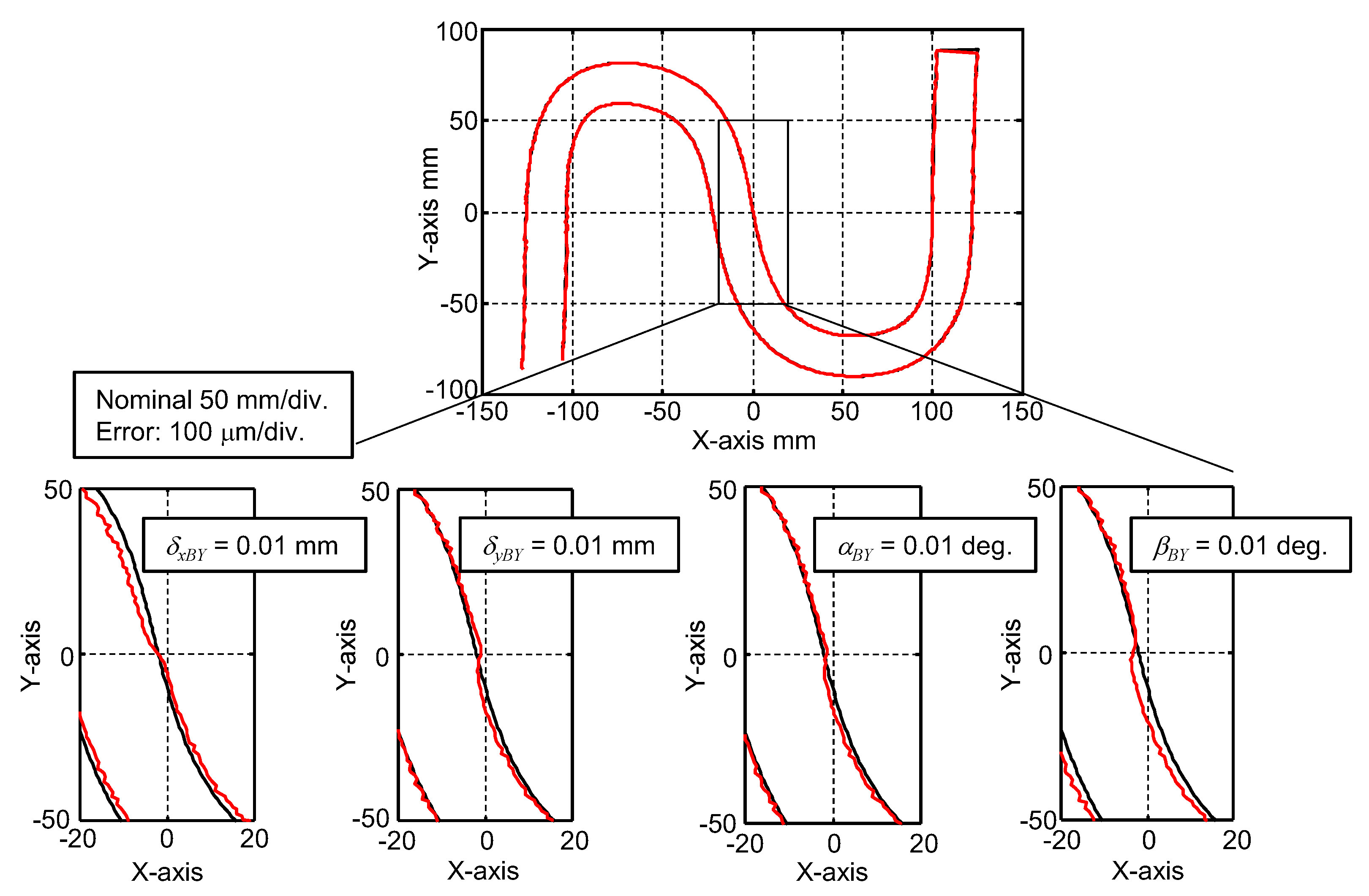
To investigate the influence of geometric errors pertaining to rotary axes, motion-trajectory simulations corresponding to each geometric error were performed. In these simulations, errors of the order of 0.01 mm and 0.01° were prescribed in the matrices as the position and angular errors, respectively. It should be noted that the simulations were based on the acquired feedback positions and angles, and only the influence of geometric errors was simulated based on the geometric model. Figure 10 depicts the simulated trajectories with position and angular deviations. Although the influence of all observed errors was diagnosed in this study, results corresponding to only two position and angular errors each are depicted in the figure as examples. Because it is also confirmed that all geometric errors tend to only influence the trajectory around the center of the S-shape, the figure only depicts enlarged trajectories around the center of the S-shape.
As can be seen in the figure, each individual error traces stepwise trajectories around the 900-mm mark on Surface B because the C-axis rotates rapidly around that point, as shown in Figure 6. Unfortunately, this implies that it is impossible to investigate the influence of each geometric error based on the machined S-shape.
It is inferred from the above-mentioned results that the proposed S-shaped machining test might be effective in evaluating overall machining techniques, including the level quality of the CAD model and NC program. However, the proposed test is not exclusively effective in evaluating the accuracy of five-axis machining centers. The authors may clarify the influence of control mode of NCs and dynamics of servo systems.
6. Conclusions
This paper describes the error factors that influence the accuracy of the machined S-shape and surface quality and establishes that the proposed S-shaped machining test cannot exclusively evaluate the accuracy of five-axis machine tools through an evaluation of these factors. Influence of the tolerance of NC programs and geometric errors was also investigated. Major conclusions drawn from this study may be summarized as follows.
- (1)
- The finished shape of the machined surface in the S-shaped machining test, is strongly influenced by the quality of NC programs. Thus, machine operators must exercise care to ensure that the desired level of quality of NC programs has been appropriately set prior to using the facility.
- (2)
- Each individual geometric error of the rotary axes traces stepwise trajectories around the 900-mm mark on Surface B because the C-axis rotates rapidly around that point.
In conclusion, the proposed S-shaped machining test can be considered effective in demonstrating overall machining techniques, including the operation skill of CAD/CAM software, as a verification of the performance of five-axis machining centers.
Acknowledgments
The authors would like to sincerely acknowledge all the support from DMG MORI SEIKI Co. Ltd. and MTTRF. This work was financially supported JSPS KAKENHI (Grant-in Aid for Scientific Research (C)), Grant Number 15K05724. The authors would also like to acknowledge the support of Nakai and Ueda, students from Osaka Institute Technology and Kobe University.
Author Contributions
Ryuta Sato and Keiichi Shirase conceived the research strategy and performed relevant experiments; Yukitoshi Ihara provided 3D CAD data of the S-shaped workpiece; and Ryuta Sato wrote the manuscript.
Conflicts of Interest
The founding sponsors had no role in neither the design of the study nor in the collection, analyses, or interpretation of data; writing of the manuscript; and decision to publish the results.
References
- Ibaraki, S.; Knapp, W. Indirect Measurement of Volumetric Accuracy for Three-axis and Five-axis Machine Tools: A Review. Int. J. Autom. Technol. 2012, 6, 110–124. [Google Scholar] [CrossRef]
- ISO 230-1: Test Code for Machine Tools–Part 1: Geometric Accuracy of Machines Operating under No-load or Quasi-Static Conditions; International Organization for Standardization: Geneva, Switzerland, 2012.
- Tsutsumi, M.; Saito, A. Identification and Compensation of Systematic Deviations Particular to 5-axis Machining Centers. Int. J. Mach. Tools Manuf. 2003, 43, 771–780. [Google Scholar] [CrossRef]
- Tsutsumi, M.; Saito, A. Identification of Angular and Positional Deviations Inherent to 5-axis Machining Centers with a Tilting-rotary Table by Simultaneous Four-axis Control Movements. Int. J. Mach. Tools Manuf. 2004, 44, 1333–1342. [Google Scholar] [CrossRef]
- Tsutsumi, M.; Tone, S.; Kato, N.; Sato, R. Enhancement of Geometric Accuracy of Five-axis Machining Centers based on Identification and Compensation of Geometric Deviations. Int. J. Mach. Tools Manuf. 2013, 68, 11–20. [Google Scholar] [CrossRef]
- Bringmann, B.; Knapp, W. Model-based ‘Chace-the-ball’ Calibration of a 5-axis Machining Center. CIRP Ann. Manuf. Technol. 2006, 55, 531–534. [Google Scholar] [CrossRef]
- Weikert, S. R-test, A New Device for Accuracy Measurements on Five Axis Machine Tools. CIRP Ann. Manuf. Technol. 2004, 53, 429–432. [Google Scholar] [CrossRef]
- ISO 10791-6: Test Conditions for Machining Centres—Part 6: Accuracy of Speeds and Interpolations; International Organization for Standardization: Geneva, Switzerland, 2014.
- Xiang, S.; Altintas, Y. Modeling ad Compensation of Volumetric Errors for Five-axis Machine Tools. Int. J. Mach. Tools Manuf. 2016, 101, 65–78. [Google Scholar] [CrossRef]
- NAS 979: National Aerospace Standard; Aerospace Industries Association of America: Washington, DC, USA, 1969.
- ISO 10791-7: Test Conditions for Machining Centres—Part 7: Accuracy of Finished Test Pieces; International Organization for Standardization: Geneva, Switzerland, 2014.
- Kato, N.; Tsutsumi, M.; Sato, R. Analysis of Circular Trajectory Equivalent to Cone-frustum Milling in Five-axis Machining Centers Using Motion Simulator. Int. J. Mach. Tools Manuf. 2013, 64, 1–11. [Google Scholar] [CrossRef]
- Kato, N.; Tsutsumi, M.; Tsuchihashi, Y.; Sato, R.; Ihara, Y. Sensitivity Analysis in Ball Bar Measurement of Three-Dimensional Circular Movement Equivalent to Cone-Frustum Cutting in Five-Axis Machining Centers. J. Adv. Mech. Des. Syst. Manuf. 2013, 7, 317–332. [Google Scholar] [CrossRef]
- ISO 10791-7: 2014/DAM 1. Test Conditions for Machining Centres—Part 7: Accuracy of Finished Test Pieces; AMENDMENT 1; International Organization for Standardization: Geneva, Switzerland, 2016.
- Senatore, J.; Moniès, F.; Rubio, W. 5-Axis flank milling of sculptured surfaces. In Machining of Complex Sculptured Surfaces; Springer: Berlin, Germany, 2012; pp. 33–65. [Google Scholar]
- Sprott, K.; Ravani, B. Cylindrical Milling of Ruled Surfaces. Int. J. Adv. Manuf. Technol. 2008, 38, 649–656. [Google Scholar] [CrossRef]
- Bo, P.; Bartoň, M.; Plakhotnik, D.; Pottmannd, H. Towards Efficient 5-axis Flank CNC Machining of Free-form Surfaces via Fitting Envelopes of Surfaces of Revolution. Comput. Aided Des. 2016, 79, 1–11. [Google Scholar] [CrossRef]
- Wang, W.; Jiang, Z.; Tao, W.; Zhuang, W. A New Test Part to Identify Performance of Five-axis Machine Tool–Part I: Geometrical and Kinematic Characteristics of S Part. Int. J. Adv. Manuf. Technol. 2015, 79, 729–738. [Google Scholar] [CrossRef]
- Wang, W.; Jiang, Z.; Li, Q.; Tao, W. A New Test Part to Identify Performance of Five-axis Machine Tool–Part II: Validation of S Part. Int. J. Adv. Manuf. Technol. 2015, 79, 739–756. [Google Scholar] [CrossRef]
- Jiang, Z.; Ding, J.; Song, Z.; Du, L.; Wang, W. Modeling and Simulation of Surface Morphology Abnormality of ‘S’ Test Piece Machined by Five-axis CNC Machine Tool. Int. J. Adv. Manuf. Technol. 2016, 85, 2745–2759. [Google Scholar] [CrossRef]
- Nakai, T.; Ihara, Y. Study on the “S” Shaped Test Piece of 5-Axis Machining Center. In Proceedings of the 9th International Conference on Leading Edge Manufacturing in 21st Century, Hiroshima, Japan, 13–17 November 2017. [Google Scholar]
- Sato, R.; Sato, Y.; Shirase, K.; Campatelli, G.; Scippa, A. Finished Surface Simulation Method to Predicting the Effects of Machine Tool Motion Errors. Int. J. Autom. Technol. 2014, 6, 801–810. [Google Scholar] [CrossRef]
- Hasegawa, S.; Sato, R.; Shirase, K. Influence of Geometric and Dynamic Synchronous Errors onto Machined Surface in 5-axis Machining Center. J. Adv. Mech. Des. Syst. Manuf. 2016, 10. [Google Scholar] [CrossRef]
Figure 1.
Proposed S-shaped workpiece for ISO standard, reproduced with permission from [14].
Figure 1.
Proposed S-shaped workpiece for ISO standard, reproduced with permission from [14].
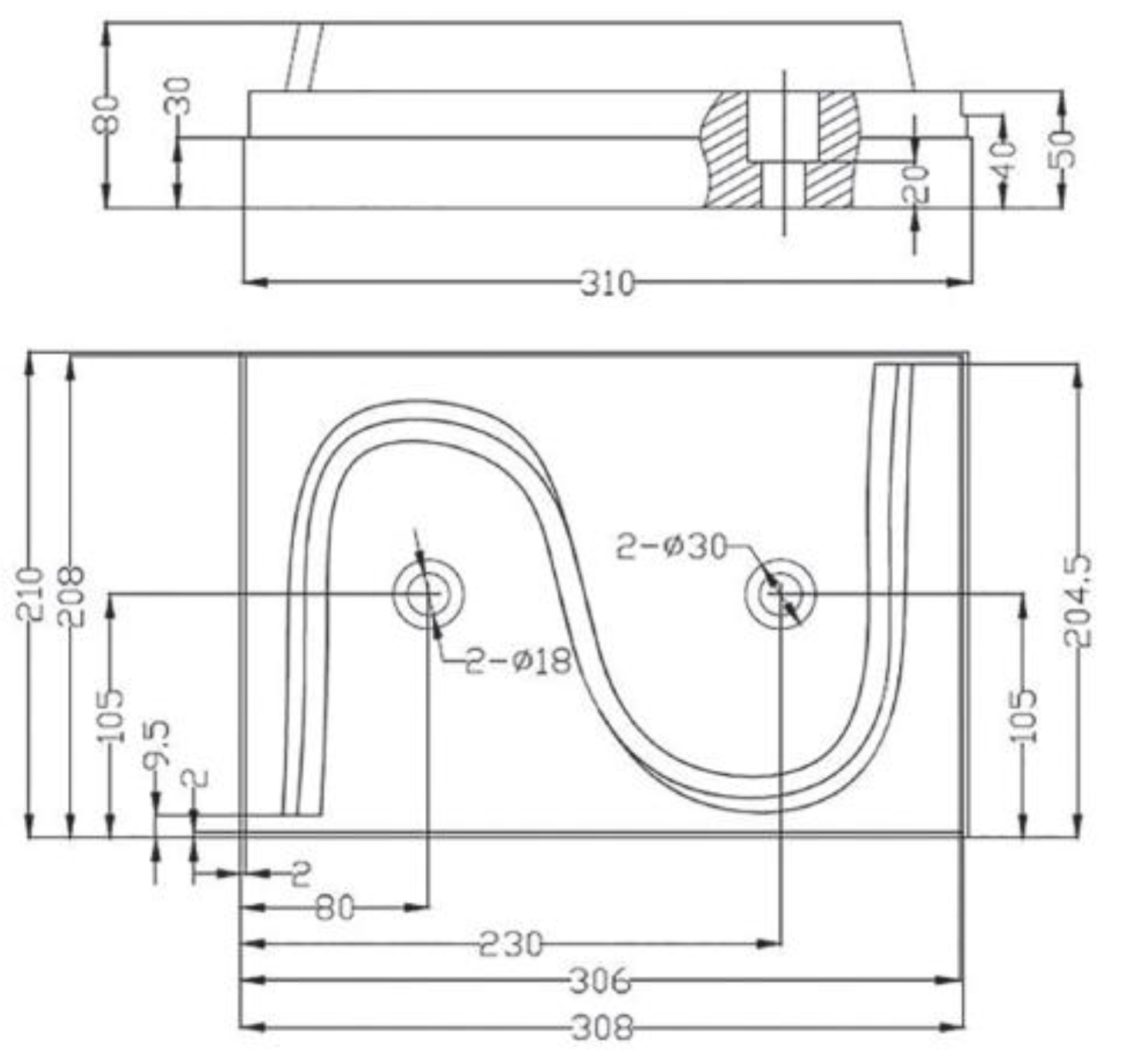
Figure 2.
Geometrical definition and 3D CAD model of the proposed S-shaped workpiece: (a) Geometrical definition described in [14]; (b) 3D CAD model generated based on geometrical definition.
Figure 2.
Geometrical definition and 3D CAD model of the proposed S-shaped workpiece: (a) Geometrical definition described in [14]; (b) 3D CAD model generated based on geometrical definition.
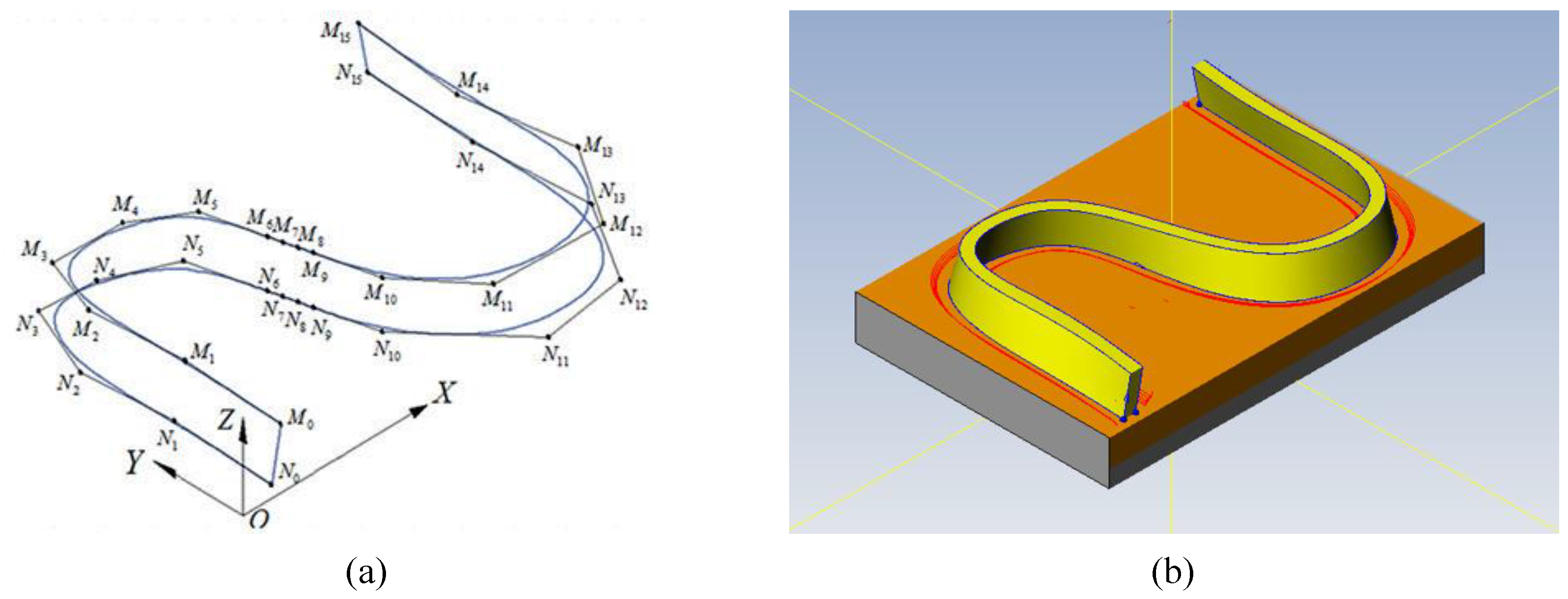
Figure 3.
Experimental method for the S-shaped machining test: (a) Structural configuration of five-axis machining center employed in this study; (b) Machining set-up of the S-shaped workpiece.
Figure 3.
Experimental method for the S-shaped machining test: (a) Structural configuration of five-axis machining center employed in this study; (b) Machining set-up of the S-shaped workpiece.
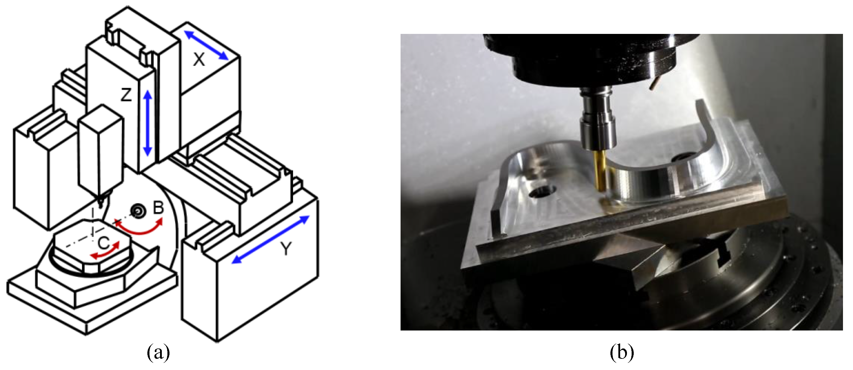
Figure 4.
Simulation method for machined workpiece with motion error sources in the five-axis machining center.
Figure 4.
Simulation method for machined workpiece with motion error sources in the five-axis machining center.

Figure 5.
Motion trajectory of the tool center-point and its displacement from starting point.

Figure 6.
Motion of each axis during the proposed S-shaped machining: (a) Motion of translational axes; (b) Motion of rotary axes.
Figure 6.
Motion of each axis during the proposed S-shaped machining: (a) Motion of translational axes; (b) Motion of rotary axes.
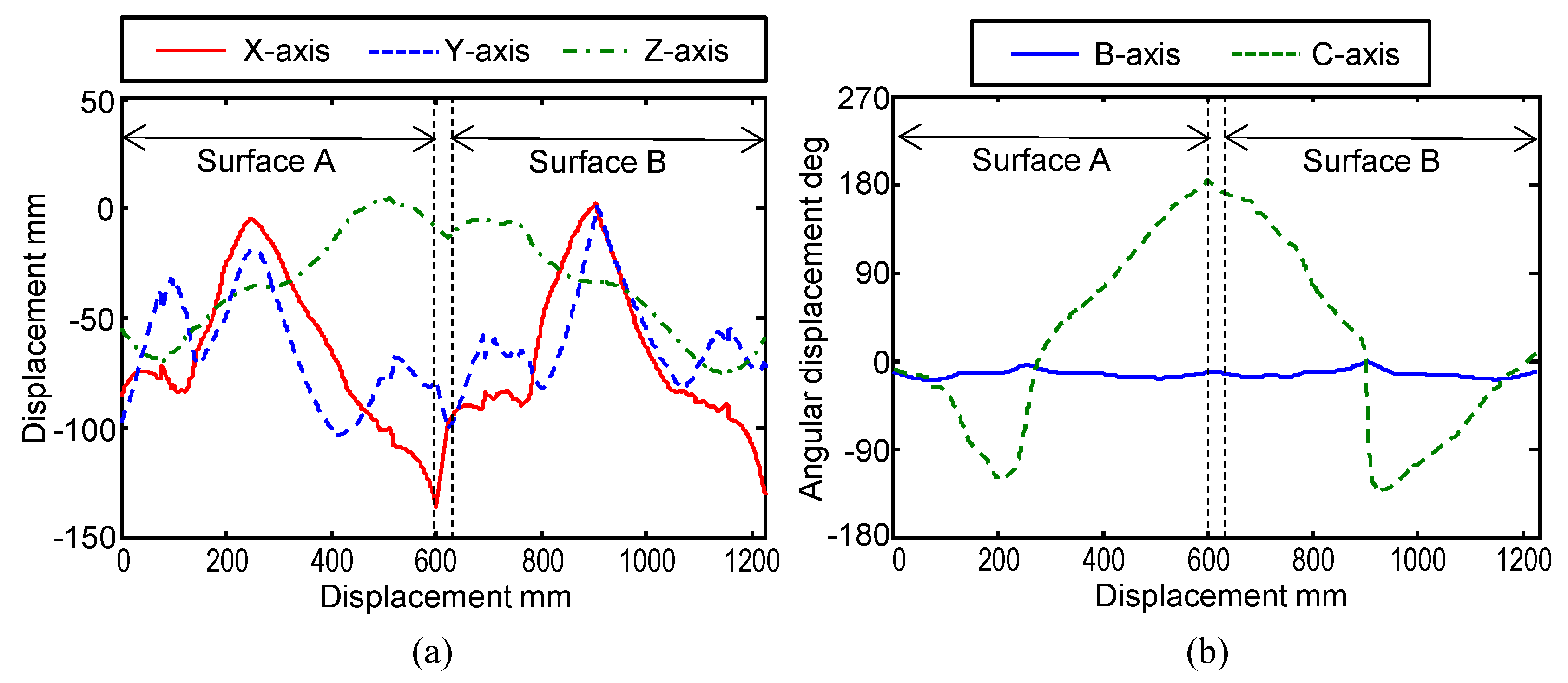
Figure 7.
Tangential velocity along the path of tool motion during S-shaped machining; the velocity is calculated from the acquired feedback positions and angles.
Figure 7.
Tangential velocity along the path of tool motion during S-shaped machining; the velocity is calculated from the acquired feedback positions and angles.
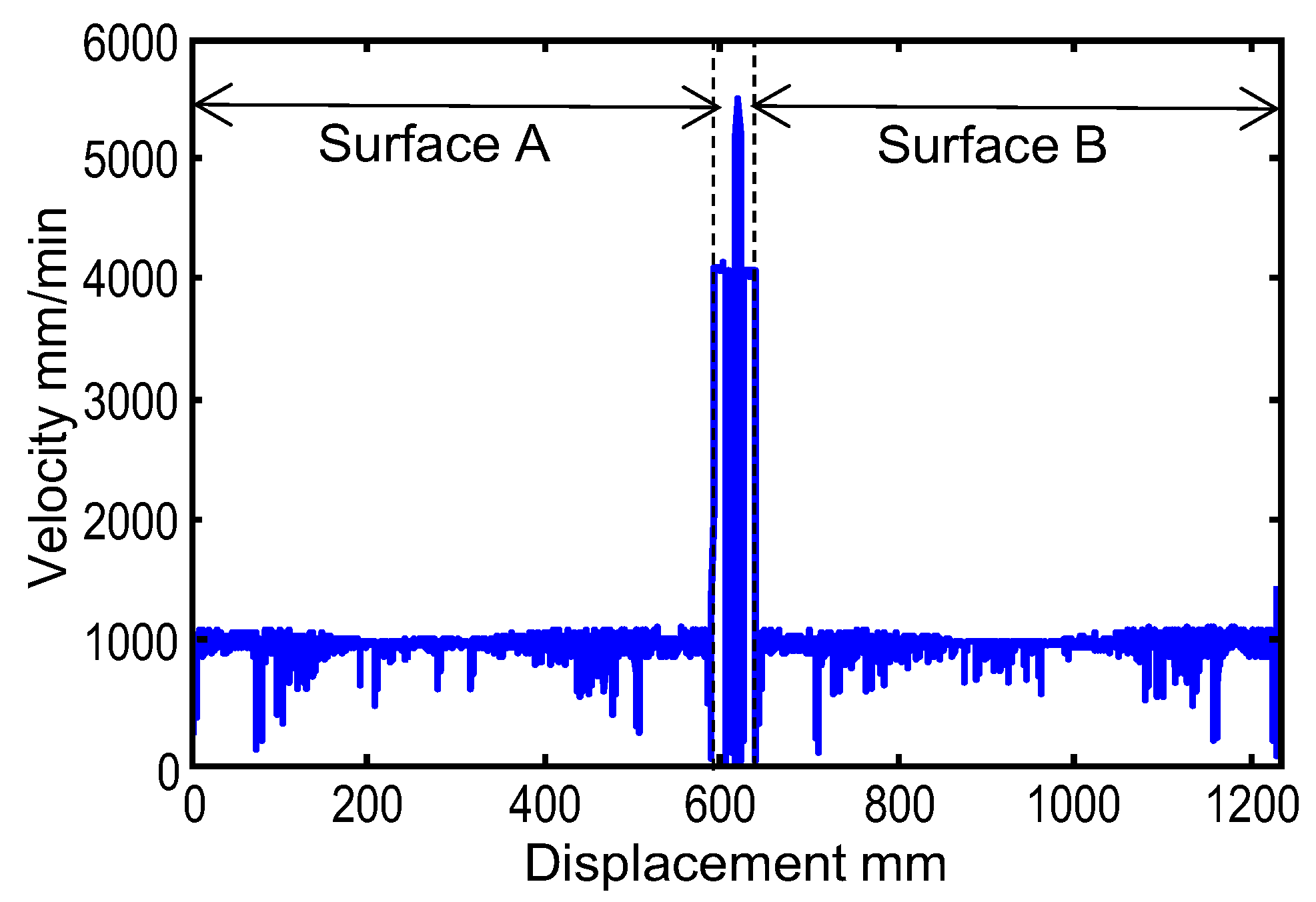
Figure 8.
Tool-motion trajectory and finished surface corresponding to the 0.01-mm tolerance case: (a) Motion trajectory of tool center-point; (b) Tool orientation error; (c) Actual and simulated finished surfaces.
Figure 8.
Tool-motion trajectory and finished surface corresponding to the 0.01-mm tolerance case: (a) Motion trajectory of tool center-point; (b) Tool orientation error; (c) Actual and simulated finished surfaces.

Figure 9.
Tool-motion trajectory and finished surface corresponding to the 0.1-mm tolerance case: (a) Motion trajectory of tool center-point; (b) Tool orientation error; (c) Actual and simulated finished surfaces.
Figure 9.
Tool-motion trajectory and finished surface corresponding to the 0.1-mm tolerance case: (a) Motion trajectory of tool center-point; (b) Tool orientation error; (c) Actual and simulated finished surfaces.

Figure 10.
Influence of geometric errors on motion trajectory of tool center-point.

Table 1.
Cutting condition.
| Tool Type | Square-End Mill |
|---|---|
| Tool diameter | 13 mm |
| Number of flutes | 2 |
| Workpiece material | A7075 |
| Radial depth of cut | 0.1 mm |
| Feed rate | 1000 mm/min |
| Spindle speed | 5000 rpm |
Table 2.
List of geometric errors of rotary axes.
| Symbol | Description |
|---|---|
| δxBY | Position error of the B-axis average line along X-axis |
| δyBY | Position error of the C-axis average line along Y-axis |
| δzBY | Position error of the B-axis average line along Z-axis |
| δxCB | Offset between B- and C-axis average lines along X-axis |
| αCB | Squareness error between B- and C-axis in the X–Y plane |
| αBY | Parallelism between the C-axis average line and Z-axis motion in the Y–Z plane |
| βBY | Parallelism between the C-axis average line and Z-axis motion in the Z–X plane |
| γBY | Parallelism between the B-axis average line and Y-axis motion in the X–Y plane |
© 2018 by the authors. Licensee MDPI, Basel, Switzerland. This article is an open access article distributed under the terms and conditions of the Creative Commons Attribution (CC BY) license (http://creativecommons.org/licenses/by/4.0/).
Share and Cite
MDPI and ACS Style
Sato, R.; Shirase, K.; Ihara, Y. Influence of NC Program Quality and Geometric Errors of Rotary Axes on S-Shaped Machining Test Accuracy. J. Manuf. Mater. Process. 2018, 2, 21. https://doi.org/10.3390/jmmp2020021
AMA Style
Sato R, Shirase K, Ihara Y. Influence of NC Program Quality and Geometric Errors of Rotary Axes on S-Shaped Machining Test Accuracy. Journal of Manufacturing and Materials Processing. 2018; 2(2):21. https://doi.org/10.3390/jmmp2020021
Chicago/Turabian StyleSato, Ryuta, Keiichi Shirase, and Yukitoshi Ihara. 2018. "Influence of NC Program Quality and Geometric Errors of Rotary Axes on S-Shaped Machining Test Accuracy" Journal of Manufacturing and Materials Processing 2, no. 2: 21. https://doi.org/10.3390/jmmp2020021