1. Introduction
Polymer optics are widely used in a broad range of applications in medical engineering, automotive industries, consumer electronics and measurement systems [
1,
2] and represent an important enabling technology for the development of many types of devices [
3]. Considering the growing demand, fast and cheap replication of polymer optics gains importance, which can be served by injection molding in order to achieve significant reduction in the fabrication costs compared to traditional glass optics [
4].
A major advantage of polymer technology is that free-form optics and micro-structured optics can be manufactured at a significantly lower price [
5]. Furthermore, the ability to include mounting features in the optical component on an economical basis allows for further cost reduction and freedom of design [
3], leading to a significant increase of applications in recent years. Examples for micro-structured optics are Fresnel-lenses and Diffractive Optical Elements (DOE) [
6,
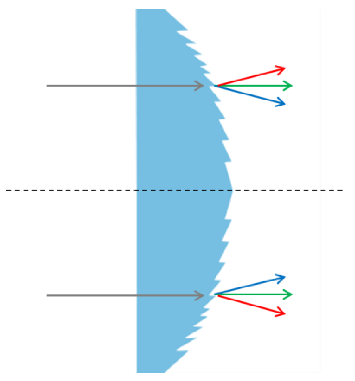
7]. However, the limited optical performance of polymer materials compared to glass prevents the replacement in different applications. Thus, high-performance polymer optics are necessary, which can only be achieved by making use of the freedom of design by combining multiple optical elements in a single lens. For example, the expansion of lens shapes to free forms and the combination of lenses with micro-structures enable such a boost in performance. Additionally, size, weight and volume of optical systems can be reduced significantly and, moreover, aberrations can be adjusted. In this work a DOE with curved surfaces is fabricated to demonstrate the injection compression molding of a complex polymer optical component. DOEs are micro-structured optical elements used to shape beams and adjust aberrations.
Injection molding is broadly used for the fabrication of polymer optics. The combination of fast replication and low cost per unit makes it a perfect method for a high-volume replication. Furthermore, the replication of free forms and micro-structures is possible. To enhance the quality of polymer optics, injection compression molding is often used [
8]. A compression stamper in the molding tool is used to create a homogeneous pressure distribution in the polymer part, leading to a reduced birefringence in polymer optics. Additionally, injection compression molding is reported to achieve better results in the replication of micro-structured components compared to traditional injection molding [
9]. A more detailed description of the process and requirements for the molding tool can be found elsewhere [
10,
11]. To fabricate high-quality polymer optics by injection (compression) molding, understanding and control of the process is mandatory, since even small variations, deviations or defects affect significantly the quality of the optical part [
12].
Injection molding and injection compression molding are often used for the replication of DOEs. Diffractive elements with binary or continuous structures and feature sizes in the (sub-) micrometer range can be fabricated [
13,
14]. Results show that the replication of the micro-structures is highly depending on the molding parameters. Optimization of molding parameters such as injection speed, shot size, mold temperature and holding pressure are important to obtain good molding results. Furthermore, the material has significant impact on the molding accuracy of DOEs [
6]. However, most of the research focuses on the molding of flat DOEs.
Since the fabrication of complex polymer optics depends on different factors and requires experience on how these factors influence each other, the development of new polymer optical systems fabricated by injection molding is costly and time consuming. This presents a significant barrier for companies to make use of the technological advantages. Regrettably, research mostly focuses on the process parameters during the molding process [
15,
16], thus, covering only a part of the fabrication process. Hence, a broader investigation and description of the fabrication processes and their influences is necessary. This work investigates different influences on the resulting molding quality and proposes a method on how high-quality optical polymer parts can be produced using injection compression molding. Influences of the mold design, runner system, temperature control and process parameters are investigated, focusing on the optimization of filling behavior, process stability and molding accuracy for the fabrication of high-quality micro-structured polymer optics.
2. Materials and Methods
In this work injection compression molding is used for the fabrication of DOEs. In comparison to regular injection molding, the cavity of the molding tool is not closed completely at the beginning of the process. The closing during and after the injection of the polymer results in a homogeneous pressure distribution within the polymer part and therefore reduces birefringence due to inhomogeneous internal stresses. The DOE is designed as a zero refractive element, combining a curved refractive shape with diffractive structures. The refractive shape and the diffractive structures are designed in a way that the diversion for one specific wavelength is zero, while for other wavelengths the diversion can be increased. Examples for the application of these elements are confocal measurement systems to examine surface topographies. The concept of a zero refractive element is shown in
Figure 1.
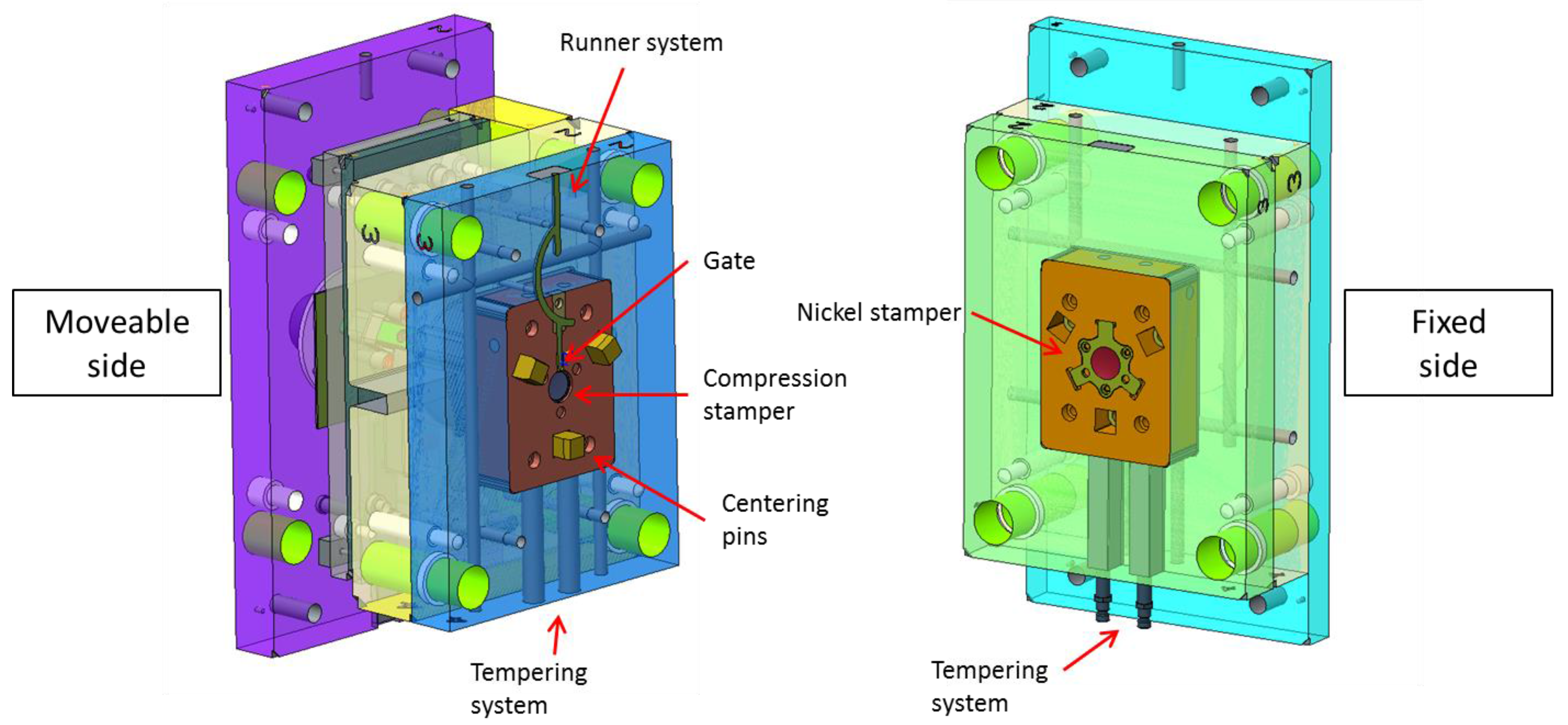
For the molding tool a mold insert is fabricated using laser direct writing on a curved glass substrate with a subsequent nickel electroplating process to produce a galvano copy of the master structure as a stamper inlay for the injection compression mold. The diffractive structures in the mold insert have a blazed structure with a height of 1.6 μm. The pitch between the blazed structures varies, reaching from 140 μm down to 5 μm. The DOE has a diameter of 22 mm and a thickness of 4.3 mm in the center. The material Trogamid myCX (Evonik Industries AG) is used for the fabrication of the DOEs. It is based on polyamide (PA 6), thus having a semi-crystalline structure, which enhances reliability against environmental influences. At the same time, it provides optimized optical properties, which makes the material perfectly suited for the application in complex polymer optical parts. The molding tool is designed as an injection compression-molding tool with a moveable compression stamper controlled by the ejector motor of the molding machine (
Figure 2). The stamper has an aspheric shape at the front, produced by ultra-precision diamond turning. The surface roughness of the stamper is Ra = 6 nm. The runner system is located in the parting line of the molding tool, thus the material is injected from the top using an injection-molding machine with a vertical injection unit. Since the runner system and the gate are crucial parts for a successful production of optical polymer parts, the gate is constructed as an exchangeable insert. In this work the shape of the gate is varied to evaluate the influences of the gate and to optimize the filling behavior of the cavity. To assure accurate positioning of the two mold sides, customized centering pins are used.
A crucial factor for the fabrication of optical polymer parts by means of injection molding is the temperature control, both of the molding tool and the material. Therefore, the temperature in the two sides of the mold as well as the compression stamper is controlled separately by three water-tempering systems. Furthermore, the temperature in the injection unit is controlled accurately, having five temperature zones as well as a tempered material inlet to assure stable conditions of the molten mass. All molding experiments are performed on an injection-molding machine with a vertical injection unit and hydraulic ejectors (Arburg ALLROUNDER 520 A, Lossburg, Germany).
The influences of the molding tool setup, peripheral influences and molding parameters on the filling behavior, process stability and molding accuracy are investigated and analyzed. Therefore, the mold setup is varied using exchangeable inserts and different molding parameters are tested and optimized.
3. Results
The experiments are divided into three steps. Firstly, the filling behavior is optimized to achieve complete filling of the mold cavity. Afterwards adjustments are made to establish a stable process window during the molding process, resulting in reproducible quality of the polymer parts. In a last step, the molding parameters are optimized to achieve the highest possible molding accuracy including the replication of the microstructures in the polymer parts.
3.1. Opimization of the Filling Behavior
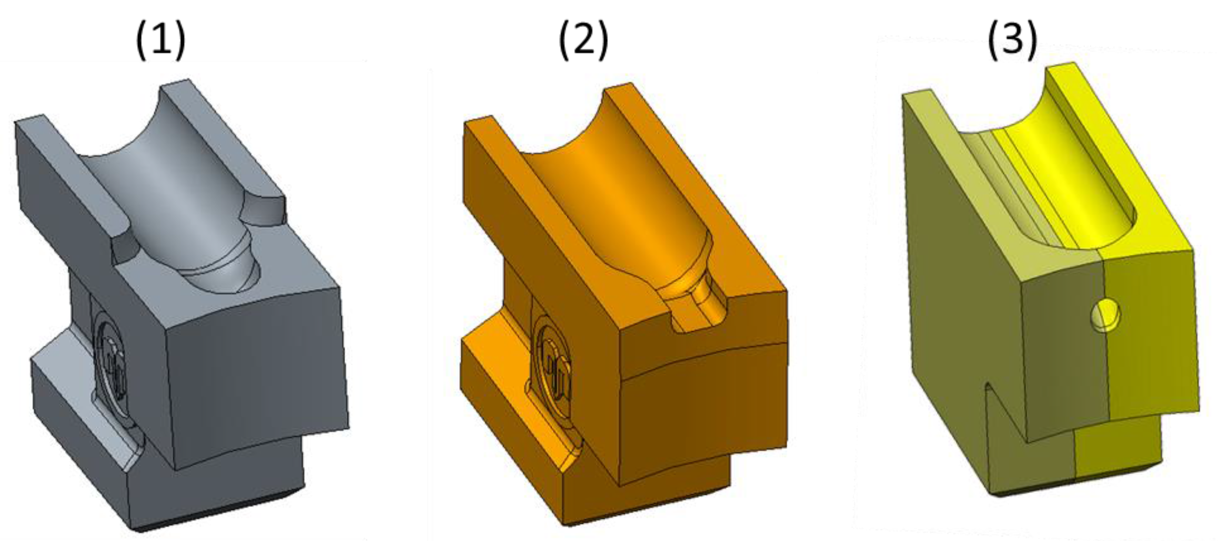
In order to achieve a good molding result, the filling behavior of the cavity is crucial. Especially when injection compression molding is applied, the flow of the material and the movement of the molding tool have to be adjusted and coordinated perfectly to each other. A multitude of factors affect the filling behavior. Examples on the mold side are the runner system and the gate. On the process side the compression movement is one of the most critical aspects. To optimize the filling behavior of the cavity, three types of gates were tested. The first gate was a film gate with dimensions of 6 × 1 mm (
Figure 3 (1)). The second one had a half-moon shape with a diameter of 2 mm (
Figure 3 (2)). The third gate was designed as a tunnel gate with a 0.8 mm opening (
Figure 3 (3)). Using a tunnel gate in combination with the vertical injection and a compression stamper has the advantage that the sprue can be cut off during the molding process. Therefore no subsequent process step to remove the sprue is necessary. The tunnel gate was designed in a way that the compression stamper passes the gate during the compression process and therefore the sprue was cut off. In contrast to the two other gate designs, the gate opening has to be small to enable this cut-off process.
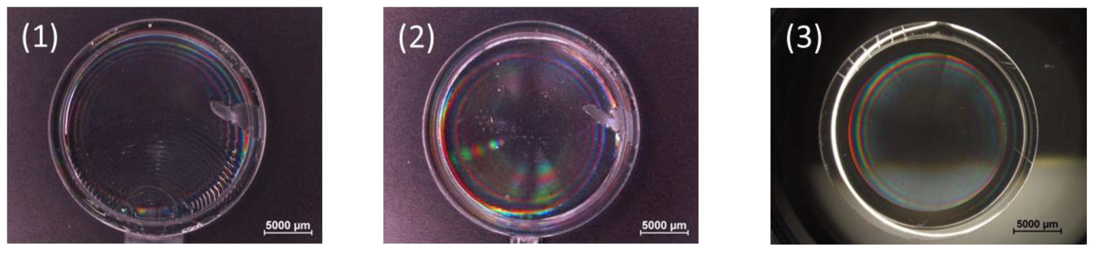
Using the film gate for the fabrication of the DOEs, a wavelike flow front was visible (
Figure 4 (1)). This leads to an unsteady filling behavior of the cavity. The DOE showing these wavelike flow lines were not acceptable as optical components. The half-moon shaped gate resulted in a homogenous filling behavior (
Figure 4 (2)). The large opening of the gate allows a fast filling of the cavity and creates a laminar flow. The tunnel gate tended to create a free-jet flow, leading to an uneven distribution of material. However, in combination with an optimized compression stamper movement, the free-jet flow can be avoided and a laminar flow into the cavity can be achieved while keeping the advantages of this type of gate (
Figure 4 (3)). Details on the stamper movement are described in the following section. For the subsequent experiments the tunnel gate is used since it combines a good filling behavior with an in-process cut-off of the sprue.
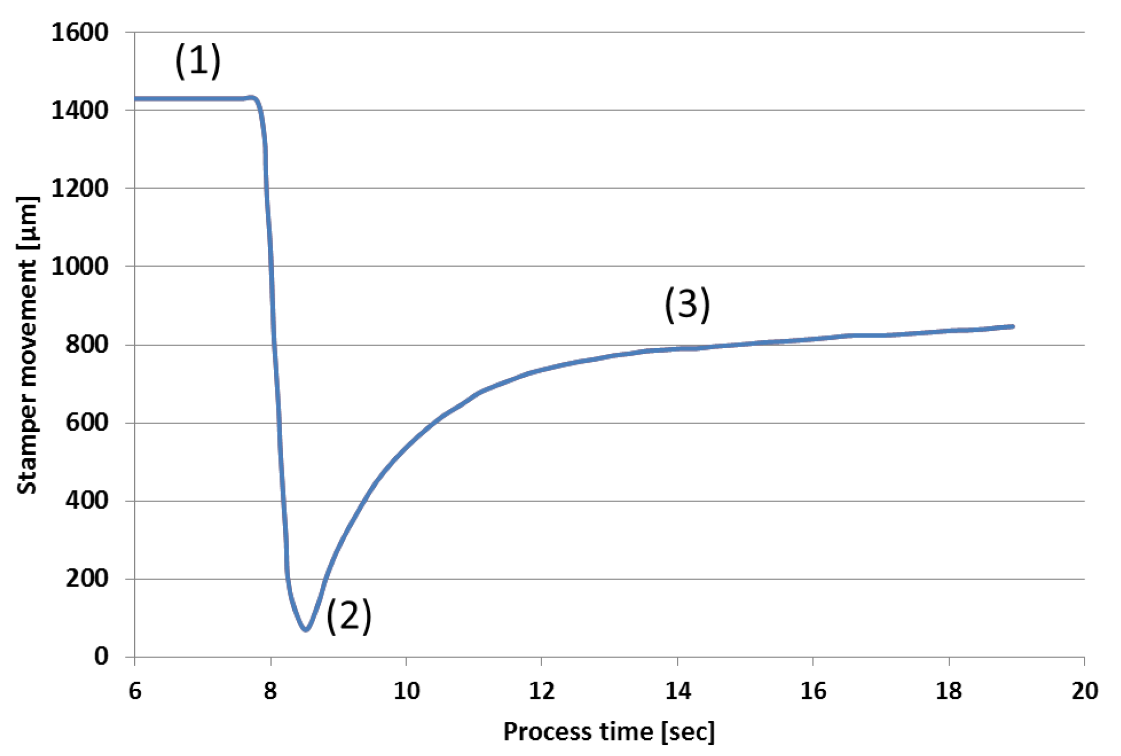
As mentioned above, the movement of the compression stamper is critical to achieve good molding results. It is one of the most important factors in injection compression molding to coordinate the injection phase with the compression movement. If the compression movement starts too early or moves too fast, the process will result in thin parts. If, on the other hand, the compression movement starts too late or moves too slow, the melt already starts cooling down and partially solidified material is compressed, leading to unwanted weld lines. Furthermore, the compression force is then not able to compress the polymer adequately. For the fabrication of the DOE the movement of the compression stamper can be divided into three steps. In the first step the compression stamper is positioned at the front end of the movement, right ahead the tunnel gate. Thus, the melt flows directly onto the stamper, avoiding a free-jet flow. To obtain the required thickness of the DOE, the compression stamper has to move back before the compression movement can start. Therefore, the pressure of the injected melt is used to push the stamper backwards. In the last step the force of the hydraulic ejector motor is used to create a compression movement, pushing the stamper forward to its final position. Thereby a constant pressure distribution within the polymer part is achieved. The timing of these three steps is crucial for a successful process. The movement of the compression stamper can be seen in
Figure 5.
3.2. Optimization of Process Stability
The production of optical polymer parts with a reproducible quality requires a high degree of process stability. Due to the injection into the parting plane based on limited space within the centering pins, a vertical injection unit was used. However, using a vertical injection unit comes with the major drawback that the melt tends to drip out of the injection nozzle during the cooling time. If during the next shot this material is injected into the cavity, an unsteady material flow will occur resulting in flow lines and inhomogeneous material density. Hence, this unwanted flow of the material has to be avoided. This can be achieved by adjusting the temperature of the injection unit, especially at the nozzle. For the fabrication of the DOEs a negative temperature profile in the injection unit shows the best results: the highest temperature is found close to the material inlet and the temperature decreases in the melt-zones closer to the nozzle. Using the negative temperature profile allows a thoroughly and homogenous melting of the material and avoids the unwanted material flow out of the nozzle during the cooling time. Details on the temperatures will be described in the following chapter.
Another issue that has to be avoided is the formation of threads during the molding process. These threads can occur, when the temperature in the nozzle is too high. In this case, a long thread can be formed when the nozzle is lifted off the mold after the material injection. The thread usually sticks to the sprue of the molded part. Since parts of the thread remain in the nozzle, partly solidified material will be injected into the cavity with the next shot, thus leading to the previously described problems. On the other hand, cold plugs that are formed in the nozzle tip during the cooling time have to be extracted by sticking to the sprue. If solidified material is present not as a thread but as a cold plug, the solidified material can be removed out of the nozzle by sticking to the sprue of the previous part. Therefore no cold material will be injected during the next injection cycle.
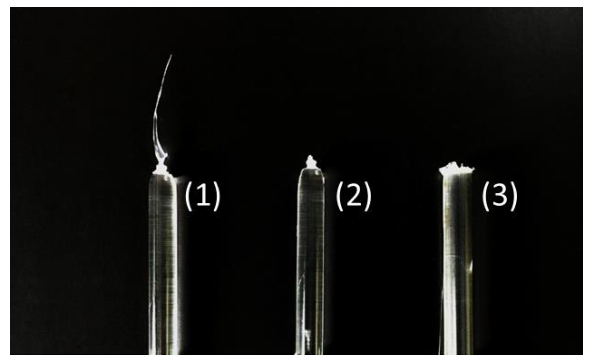
In addition to the temperatures in the nozzle and the screw in the injection unit, the temperature at the material inlet already affects the formation of cold plugs and threads, in particular in interaction with the nozzle and sprue temperatures. Therefore the material inlet has to be tempered to provide a constant temperature and in return to achieve a uniform quality of the molded parts. Experiments were performed without tempering of the material inlet, as well as temperatures of 50 °C and 73 °C at the material inlet. If no additional tempering for the material inlet is applied, the cold plug is not removed from the nozzle tip, leading to flow lines and streaks in the polymer part (
Figure 6 (3)). When the temperature at the material inlet is tempered at 50 °C, a part of the cold plug is removed by sticking to the sprue, but still some solidified material remains in the nozzle affecting the quality of the molded parts (
Figure 6 (2)). The best results can be achieved when the temperature is set to 73 °C. This temperature is chosen, since it is the resulting temperature at material inlet, when a continuous molding process is established. However, interruptions during the molding process affect the temperature at the material inlet. Therefore additional tempering of the material inlet is advisable. The cold plug can be removed completely during the demolding process and sticks to the sprue when the material inlet is set to 73 °C (
Figure 6 (1)). In the subsequent part no flow lines or streaks are apparent.
It is important to mention that a tempered material inlet is important to ensure a stable molding process with reproducible part quality. Without the temperature control, the temperature at the material inlet changes over time due to heat transfer in the molding machine. The temperature change results in irregular melt conditions.
3.3. Optimization of Molding Accuracy
Once a stable molding process is achieved, process parameters have to be adjusted to achieve the highest possible quality of the parts. It is important to mention that to start optimizing the parameters, a stable process has to be ensured as described in the previous section. Otherwise changes in the molding parameters will be superimposed by fluctuations of peripheral influences. Thus, the effect of changed parameters cannot be assigned to the resulting parts and the quality will vary. For the fabrication of DOEs by injection compression molding, three process parameters showed major influences on the molding accuracy:
Melt temperature
Mold temperature
Compression force
In particular for the molding of optical polymer parts with microstructures, these parameters have to be optimized to achieve a perfect demolding.
Table 1 shows the molding parameters used for the experiments.
The melt temperature is an important process parameter, affecting the transparency and molding accuracy especially when small features have to be replicated. As already mentioned in
Section 3.2, the temperature range of the melt is limited when using a vertical injection unit. For this experiment the highest possible temperature profile was 265/260/280/285/290/73 °C. 265 °C was set at the nozzle to avoid dripping of material during cooling time. The maximum temperature in the injection unit was 290 °C, presenting an average value within the recommended temperature range of 280–310 °C in the datasheet [
17]. Further increase of the melt temperature leads to the mentioned leakage effect. The negative temperature profile in the injection unit prevents the leakage and correlates with the recommendations of the material producer.
The recommended mold temperature for Trogamid myCX is 60–90 °C [
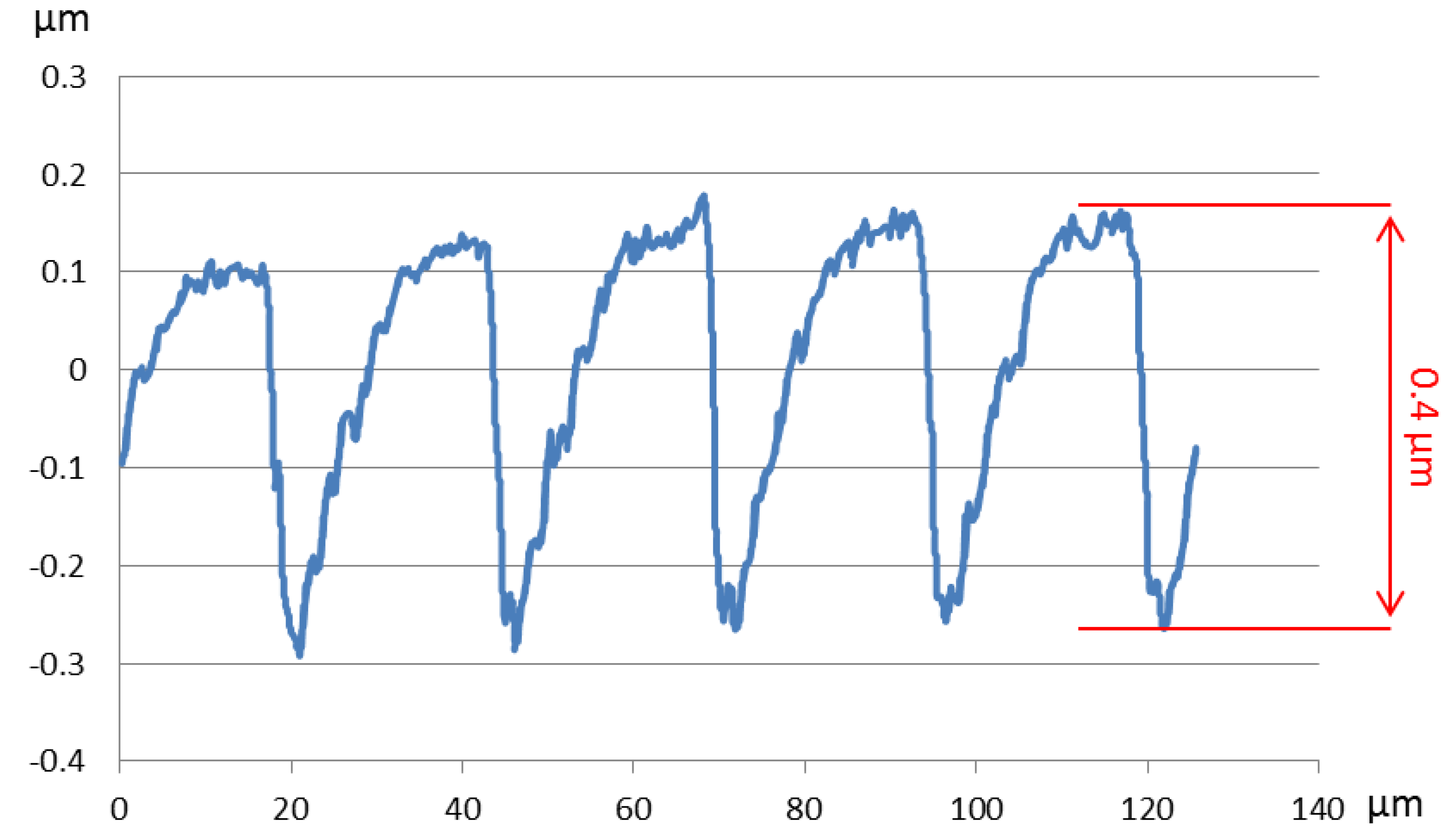
17]. For optical components it is recommended to apply high mold temperatures in order to obtain a homogeneous material distribution in the cavity. When the mold temperature was varied, the temperature profile was kept constant with the temperature profile described in the previous section and the compression force was set to 25 kN. When the mold temperature was set to 90 °C, DOEs can be produced by injection compression molding, but the diffractive microstructures are not fully replicated. As shown in
Figure 7, the resulting diffractive structures have a height of 0.4 μm, which is significantly smaller than the expected 1.6 μm from the Nickel stamper.
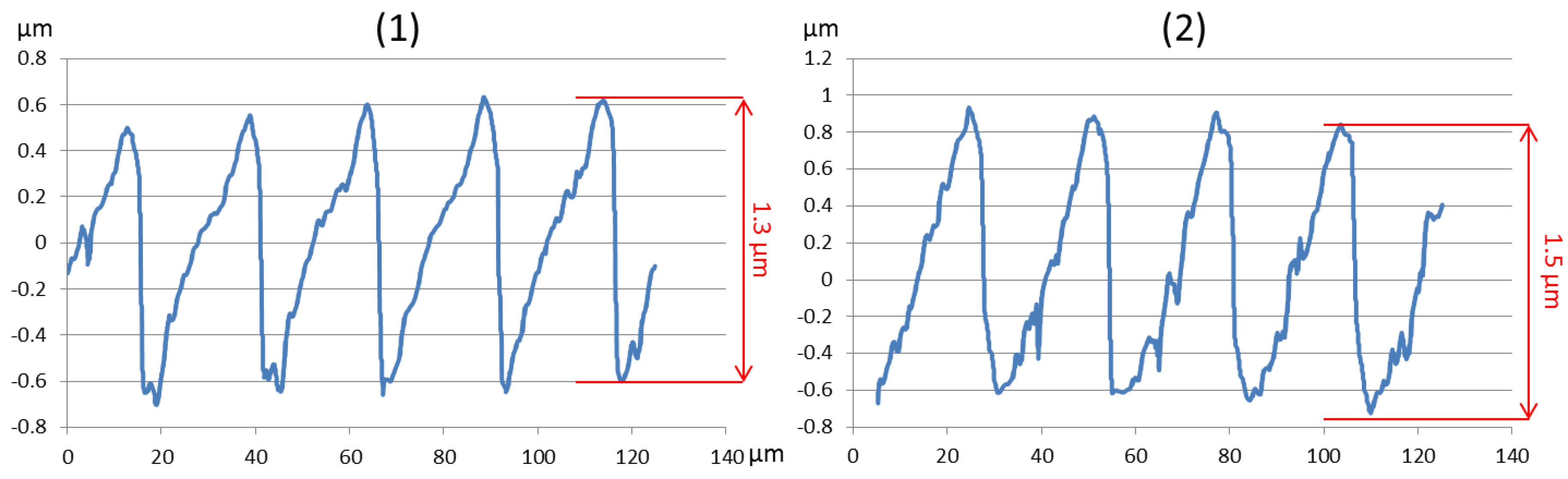
Consequently, the mold temperature was increased up to 150 °C, exceeding the recommended temperature significantly. It needs to be mentioned that the temperature is only increased on the mold side of the micro-structured insert. The ejector mold side and the compression stamper were tempered to 90 °C, since high temperatures lead to material stretching, which may affect the movement of the stamper and ejectors. The results show that if the mold temperature is increased, the replication of the microstructures improves significantly. At a temperature of 110 °C, the microstructures on the molded DOE showed a height of 1.3 μm (
Figure 8 (1)). At 150 °C mold temperature, the microstructures could be almost completely replicated with a structure height of 1.5 μm (
Figure 8 (2)). Since 150 °C presents the maximum temperature that could be reached with the available temperature control system, the compression force had to be increased for further improvement of the molding accuracy. Negative effects of the high mold temperature on the polymer did not occur.
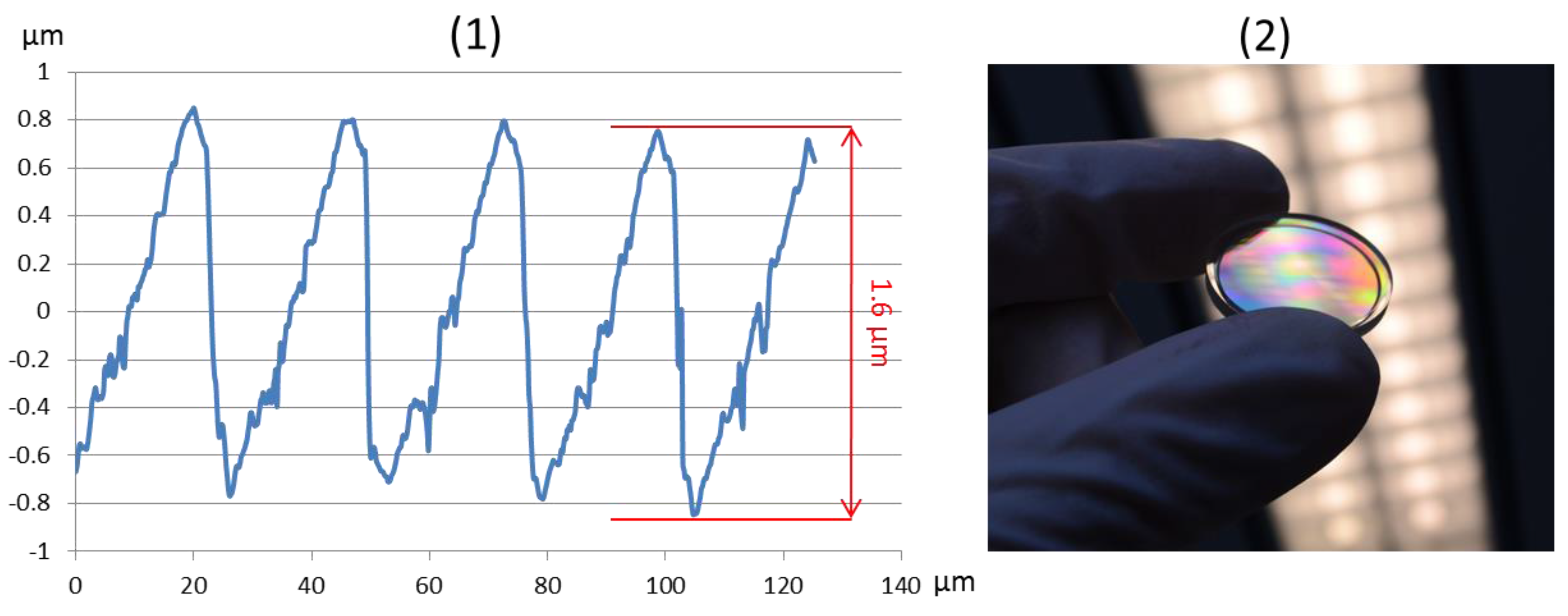
The compression force, applied by the compression stamper, was varied from 25 to 40 kN to achieve a full replication of the diffractive microstructures. Mold and melt temperature were kept constant at the previously described values. If the compression force is increased, the holding pressure is adjusted to preserve a constant part thickness of 4.3 mm. Therefore, the holding pressure was varied from 450 to 800 bar. Using a compression force of 30 kN resulted in a complete replication of the diffractive structures with a height of 1.6 μm, which corresponds to the structure size in the mold insert. Higher forces did not lead to any improvements for the optical element.
Figure 9 shows the height profile of the molded DOE as well as a final part.
4. Discussion
The results of the experiments showed that for the fabrication of micro-structured optical elements by injection compression molding, total process control is mandatory since in optical parts all molding deviations are immediately visible. The process parameters that created the best molding result are presented in
Table 2. However, small changes in the molding conditions may affect the molding process significantly, resulting in unsatisfactory optical polymer parts.
The proposed approach to fabricate optical components by injection compression molding, namely starting with optimization of the filling behavior, followed by setting up stable process conditions and finally optimizing the process parameters, has been proven as an efficient method.
The optimized process parameters acquired in these experiments cannot be directly transferred to other applications, since they are always depending on the part and mold design. Nevertheless, several general findings of the experiments can be adopted and generally used for the fabrication of optical components, especially when the parts contain micro-structures.
Molding tools with a tunnel gate can be used for the fabrication of micro-structured optical parts. In combination with a compression stamper this gate type has significant advantages because the sprue can be cut off during the process. Therefore, no additional processing step is necessary. A subsequent cut-off of the sprue can potentially also affect the optical part negatively.
High process stability is required to produce a constant quality of optical parts. Therefore, the process conditions have to be monitored and controlled constantly. This also includes the material inlet at the feeder gate. Changes in the temperature at the inlet lead to variations in the molding results, thus the material inlet needs to be temperature controlled, too. It also proved to be effective to establish a stable process window by controlling the peripheral factors and to optimize the process parameters afterwards. Otherwise changes in the conditions will superimpose with changes in the process parameters and the effect on the molding result can hardly be distinguished.
High mold temperatures support the replication of fine micro-structures. Thereby the mold temperatures can exceed the recommended temperatures by the material producer significantly. To obtain a high degree of temperature control in the molding tool, multiple discrete tempering circuits are advisable.
Beside the mold temperature, the compression force is an important factor for the replication of fine micro-structures. The compression force creates the pressure in the cavity, which is necessary to obtain a homogeneous pressure distribution. Furthermore, the melt is pushed into the fine micro-structures of the mold insert. Therefore, increased compression force supports the replication.
Acknowledgments
The research presented in this paper is supported from the budget of the Federal Ministry of Economic Affairs (Project AiF-RP-No. 18556 N). We would like to thank the funding organization. We would like to thank Arburg for providing access to the injection-molding machine and Rolf-Uwe Müller for supporting the molding experiments.
Author Contributions
Marcel Roeder designed and conducted the experiments, analyzed the resulting parts and wrote the manuscript. Peter Schilling designed the molding tool and organized the fabrication. Daniel Hera supported the design and execution of the experiments. Thomas Guenther and André Zimmermann critically revised the manuscript, supervised the project and provided the funding.
Conflicts of Interest
The authors declare no conflict of interest.
References
- Beich, W.S. Injection molded polymer optics in the 21st Century. In Proceedings of the International Society for Optics and Photonics, San Diego, CA, USA, 31 July–4 August 2005. [Google Scholar]
- Kwon, S.; Milanovic, V.; Lee, L.P. Vertical microlens scanner for 3D imaging. In Proceedings of the Technical Digest of the 2002 Solid-State Sensor and Actuator Workshop, Hilton Head Island, SC, USA, 2–7 June 2002. [Google Scholar]
- Beich, W.S. Plastic Optics: Specifying Injection-Molded Polymer Optics; Photonics Media: Pittsfield, MA, USA, 2010. [Google Scholar]
- Fang, F.; Zhang, N.; Zhang, X. Precision injection molding of freeform optics. Adv. Opt. Technol. 2016, 5, 303–324. [Google Scholar] [CrossRef]
- Doushkina, V. Advantages of Polymer and Hybrid Glass-Polymer Optics. Photonics Spectra 2010, 44, 54–58. [Google Scholar]
- Holthusen, A.-K.; Riemer, O.; Schmütz, J.; Meier, A. Mold machining and injection molding of diffractive microstructures. J. Manuf. Process. 2017, 26, 290–294. [Google Scholar] [CrossRef]
- Lin, C.-M.; Hsieh, H.-K. Processing optimization of Fresnel lenses manufacturing in the injection molding considering birefringence effect. Microsyst. Technol. 2017, 23, 5689–5695. [Google Scholar] [CrossRef]
- Sortino, M.; Totis, G.; Kuljanic, E. Comparison of Injection Molding Technologies for the Production of Micro-optical Devices. Procedia Eng. 2014, 69, 1296–1305. [Google Scholar] [CrossRef]
- Wu, C.-H.; Chen, W.-S. Injection molding and injection compression molding of three-beam grating of DVD pickup lens. Sens. Actuators A Phys. 2006, 125, 367–375. [Google Scholar] [CrossRef]
- Michaeli, W.; Schöngart, M. Mold Design for Complex Optical Plastics Components. In Fabrication of Complex Optical Components; Brinksmeier, E., Riemer, O., Gläbe, R.M., Eds.; Lecture Notes in Production Engineering; Springer: Berlin/Heidelberg, Germany, 2013; pp. 13–24. [Google Scholar]
- Bäumer, S. Handbook of Plastic Optics; John Wiley & Sons: Hoboken, NJ, USA, 2011. [Google Scholar]
- Michaeli, W.; Heßner, S.; Klaiber, F.; Forster, J. Geometrical Accuracy and Optical Performance of Injection Moulded and Injection-compression Moulded Plastic Parts. CIRP Ann. Manuf. Technol. 2007, 56, 545–548. [Google Scholar] [CrossRef]
- Nikolajeff, F.; Jacobsson, S.; Hård, S.; Billman, Å.; Lundbladh, L.; Lindell, C. Replication of continuous-relief diffractive optical elements by conventional compact disc injection-molding techniques. Appl. Opt. 1997, 36, 4655–4659. [Google Scholar] [CrossRef] [PubMed]
- Kalima, V.; Pietarinen, J.; Siitonen, S.; Immonen, J.; Suvanto, M.; Kuittinen, M.; Mönkkönen, K.; Pakkanen, T.T. Transparent thermoplastics: Replication of diffractive optical elements using micro-injection molding. Opt. Mater. 2007, 30, 285–291. [Google Scholar] [CrossRef]
- Kashyap, S.; Datta, D. Process parameter optimization of plastic injection molding: A review. Int. J. Plast. Technol. 2015, 19, 1–18. [Google Scholar] [CrossRef]
- Dick, L.; Risse, S.; Tünnermann, A. Process influences and correction possibilities for high precision injection molded freeform optics. Adv. Opt. Technol. 2016, 5. [Google Scholar] [CrossRef]
- Evonik Industries. Evonik Industries TROGAMID myCX 2017; Evonik Industries: Essen, Germany.
© 2018 by the authors. Licensee MDPI, Basel, Switzerland. This article is an open access article distributed under the terms and conditions of the Creative Commons Attribution (CC BY) license (http://creativecommons.org/licenses/by/4.0/).


