Article

Error Separation Method for Precision Measurement of the Run-Out of a Microdrill Bit by Using a Laser Scan Micrometer Measurement System

Department of Finemechanics, Tohoku University, Sendai 980-8579, Japan
*
Author to whom correspondence should be addressed.
J. Manuf. Mater. Process. 2018, 2(1), 4; https://doi.org/10.3390/jmmp2010004
Submission received: 27 November 2017 / Revised: 9 January 2018 / Accepted: 9 January 2018 / Published: 12 January 2018
(This article belongs to the Special Issue Precision Manufacturing)

Abstract

:
This paper describes an error separation method for a precision measurement of the run-out of a microdrill bit by using a measurement system consisting of a concentricity gauge and a laser scan micrometer (LSM). The proposed error separation method can achieve a sub-micrometric measurement accuracy of the run-out of the microdrill bit without the requirement of ultra-precision rotary drive devices. In the measurement, the spindle error motion of the concentricity gauge is firstly measured by using the LSM and a small-diameter artifact, instead of the conventionally used displacement probes and large-diameter artifact, in order to determine the fine position of the concentricity gauge when the spindle error motion is at its minimum. The microdrill bit is rotated at the fine position for the measurement of the run-out, so that the influence of the spindle error motion can thus be reduced, which could not be previously realized by commercial measurement systems. Experiments were carried out to verify the feasibility of the proposed error separation method for the measurement of the run-out of the microdrill bit. The measurement results and the measurement uncertainty confirmed that the proposed method is reliable for the run-out measurement with sub-micrometric accuracy.

1. Introduction

With the development of high-density printed circuit boards (PCBs) [1,2], there is an increasing demand for the microdrilling of precision holes. Compared with laser drilling [3,4] and electrochemical drilling [5,6], mechanical drilling is the most useful machining method for high aspect ratio microdrilling in practice, because it can process a variety of materials with finer quality at lower cost [7,8,9,10]. To satisfy the requirement of high aspect ratio microdrilling on the PCBs, efforts have been devoted to designing and manufacturing microdrill bits with large aspect ratios [9,10,11,12,13,14]. Due to the large aspect ratio and the low rigidity of the microdrill bit, an axial straightness error between the shank part and the body part is very likely to occur, even when manufactured by using ultra-precision grinding tools. As shown in Figure 1, when the microdrill bit is being rotated, the run-out caused by the axial straightness error is generated at the end point of the microdrill bit. The run-out of the microdrill bit would lead to an enlargement of the diameter of the drilled hole [15] and the occurrence of burrs around the hole [16], consequently reducing the hole quality in the PCBs drilling [17]. For the quality control of both PCBs drilling and microdrill bit processing, it is desired to precisely measure the degree of the run-out of the microdrill bit.
Previous research studies [15,16], rotated microdrill bits with ultra-precision rotary drive devices. A sub-micrometric measurement accuracy of the run-out has been achieved based on the rotation accuracy of the ultra-precision rotary drive devices, such as the ultra-precision spindle. On the other hand, measurement of the run-out with sub-micrometric accuracy in machine shops is required in industries, so that a straightening process can be carried out for quality control of the microdrill bit. However, it is difficult to apply the ultra-precision rotary drive devices for the run-out measurement with sub-micrometric accuracy in machine shops, because the ultra-precision spindle is sensitive to the large environmental disturbances of machine shops, such as vibrations. Moreover, the sophisticated installation of microdrill bits onto the ultra-precision spindle, in which the axis microdrill bit is required to be aligned coaxially with the axis of rotation of the spindle, is a time-consuming procedure that is not convenient for industrial measurement.
A laser scan micrometer (LSM) measurement system is being used in industries for the measuring the run-out of microdrill bits. This process is shown in Figure 2, which is composed of the LSM and a concentricity gauge. The shank part of the microdrill bit is rotationally supported by a pair of main rollers and the top roller of the concentricity gauge [18], which the microdrill bit can be easily installed onto compared with a spindle. The motion of the body part of the microdrill bit is monitored by the LSM for the run-out measurement. The concentricity gauge is robust enough to be insensitive to vibrations, but the spindle error motion of the concentricity gauge is relatively large, which is mainly caused by the assembly errors and the roundness error of the two main rollers. The spindle error motion of the concentricity gauge limits the measurement system to obtain the required sub-micrometric measurement accuracy of the run-out. In order to achieve the required measurement accuracy for the run-out by using the LSM measurement system, the separation of the spindle error motion of the concentricity gauge is necessary.
This paper describes an error separation method for the precision measurement of the run-out of a microdrill bit by the LSM measurement system. The measurement principle of the run-out by using the LSM measurement system is presented, and the influence of the spindle error motion of the concentricity gauge in the measurement of the run-out is discussed. To achieve a precision measurement of the run-out, the method for separating the spindle error motion in the measurement of the run-out is proposed. After a description of the measurement principle, experiments and an uncertainty analysis are carried out to verify the feasibility and the accuracy of the proposed method.

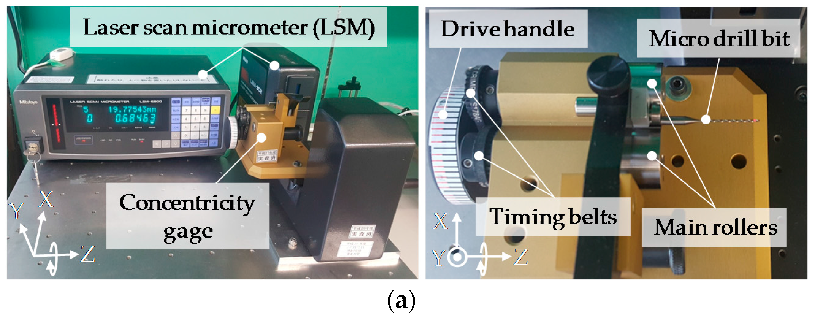
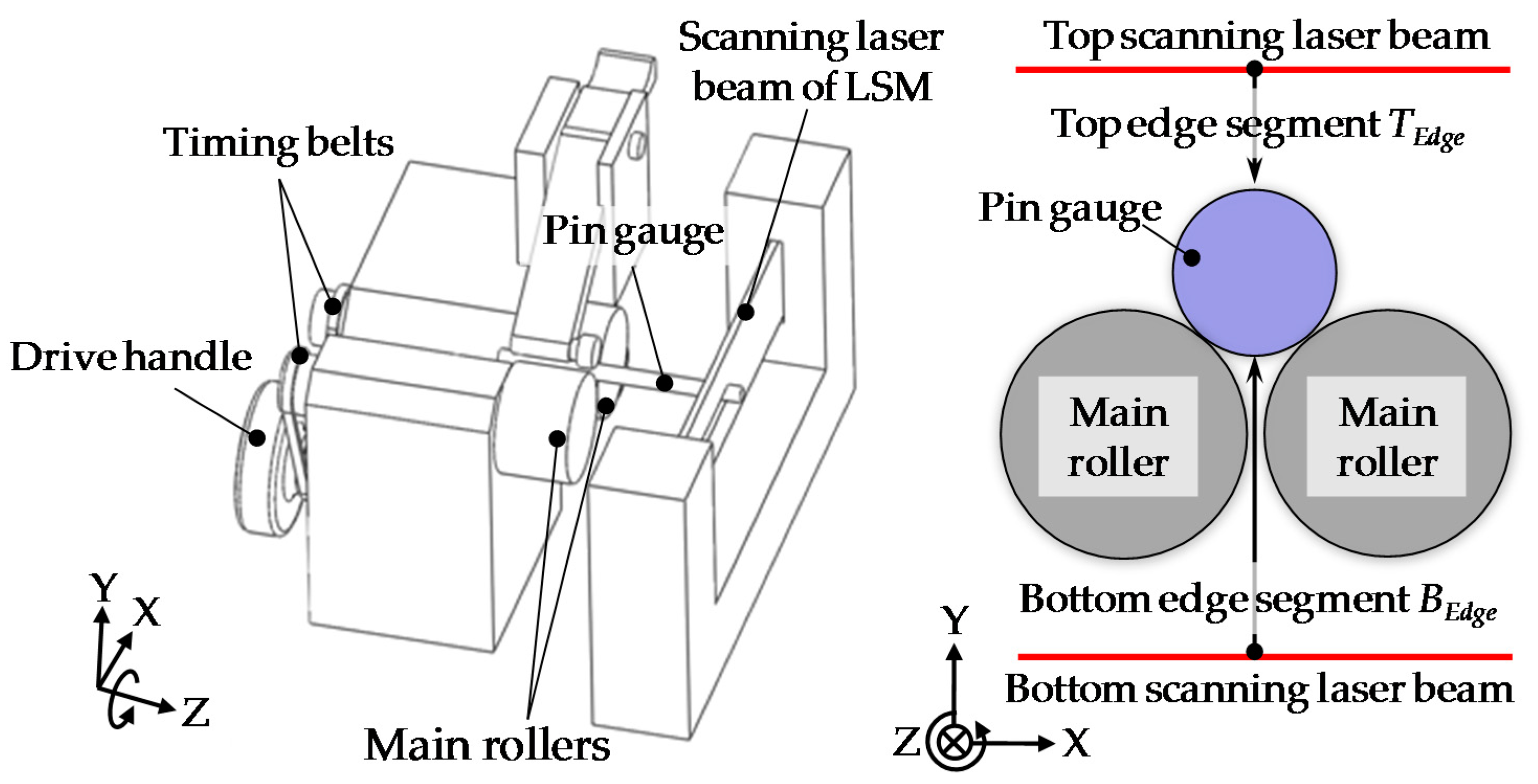
2. Measurement System and Principle

Figure 2 shows photographs and the schematics of the laser scan micrometer measurement system. The measurement system is composed of the concentricity gauge and the LSM. The shank part of the microdrill bit is gripped by the two main rollers and the top roller. Two timing belts connect the shaft of the drive handle and the shafts of the two main rollers. Through manually rotating the drive handle, the two main rollers are simultaneously rotated by the two timing belts to drive the microdrill bit by the friction between the surface of the shank part and the surface of the main rollers. Since the diameters of the shaft of the drive handle and the shafts of the main rollers are the same, the rotations of the drive handle and the main rollers are synchronized. It should be noted that when the diameters of the shank part of the microdrill bit and the main rollers are different, one revolution of the microdrill bit would only correspond to a portion of one revolution of the mail rollers.
The LSM includes a measurement part and a controller. The principle of the measurement part of the LSM is shown in Figure 3 [19]. A laser beam is reflected by a rotating polygonal mirror to scan within a measurement area. The microdrill bit that has been placed into the measurement area interrupts the laser beam, and cuts the measurement area into three measurement segments, which are referred to as the top edge segment, the diameter segment, and the bottom edge segment. The top edge segment is the distance from the top scanning position to the upper surface of the microdrill. The diameter segment is the distance between the upper surface and the lower surface of the microdrill bit. The bottom edge segment is the distance from the bottom scanning position to the lower surface of the microdrill bit. The laser beams within the top edge segment and the bottom edge segment are focused by a condenser lens, and then received by a photoelectric element, while the laser beam within the diameter segment is blocked by the microdrill bit. After converting the received signal of the photoelectric element to time domain based on detection, outputs of the top edge segment and the diameter segment, as well as the bottom edge segment in each scanning cycle, can be obtained by utilizing the known scan speed of the LSM.

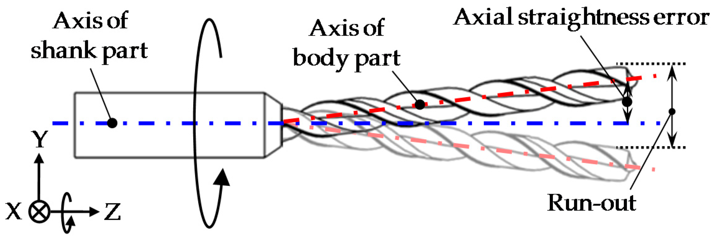
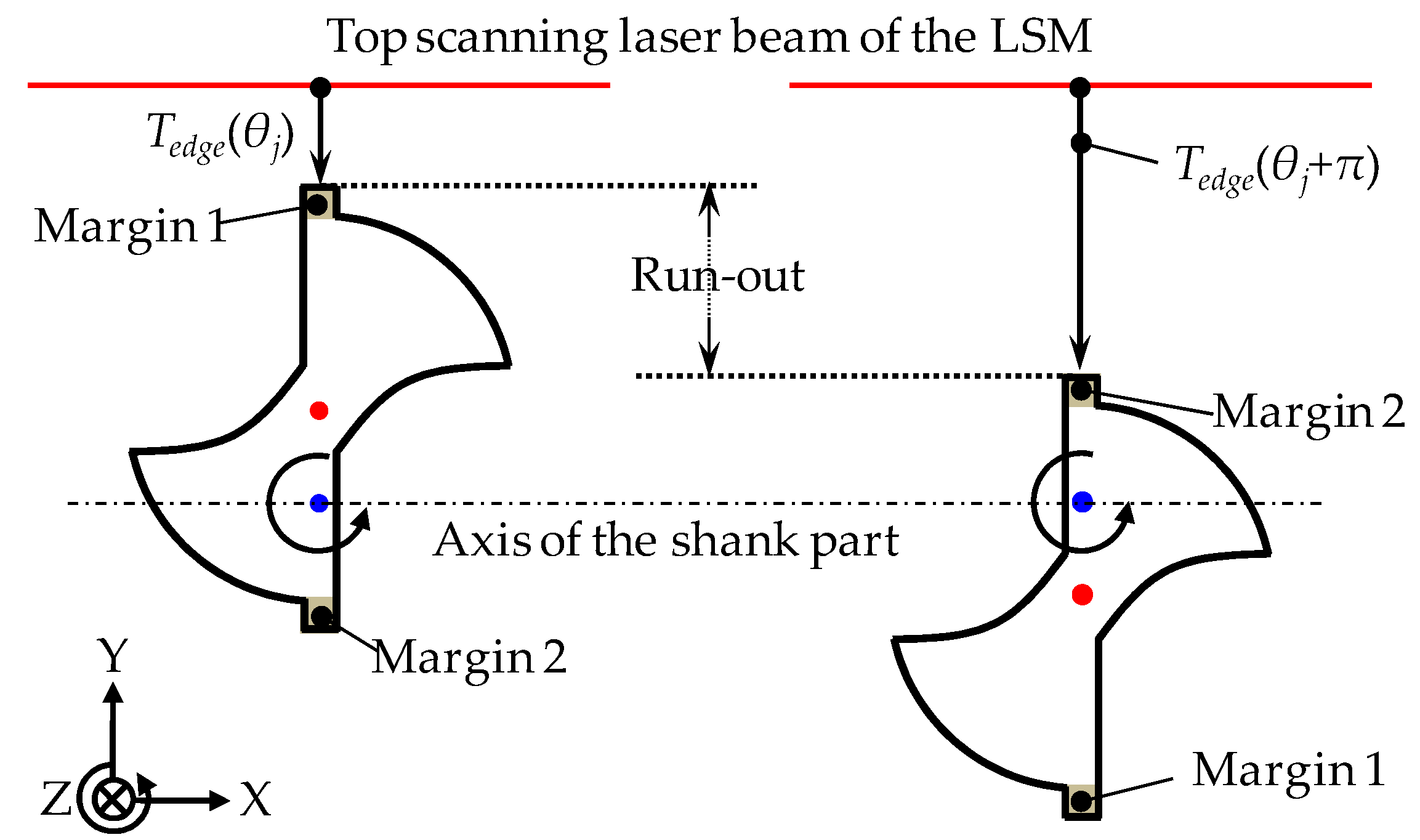
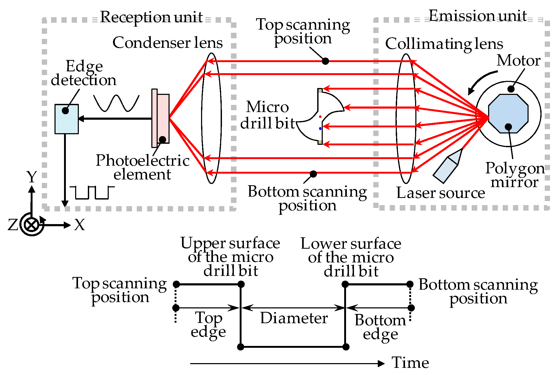
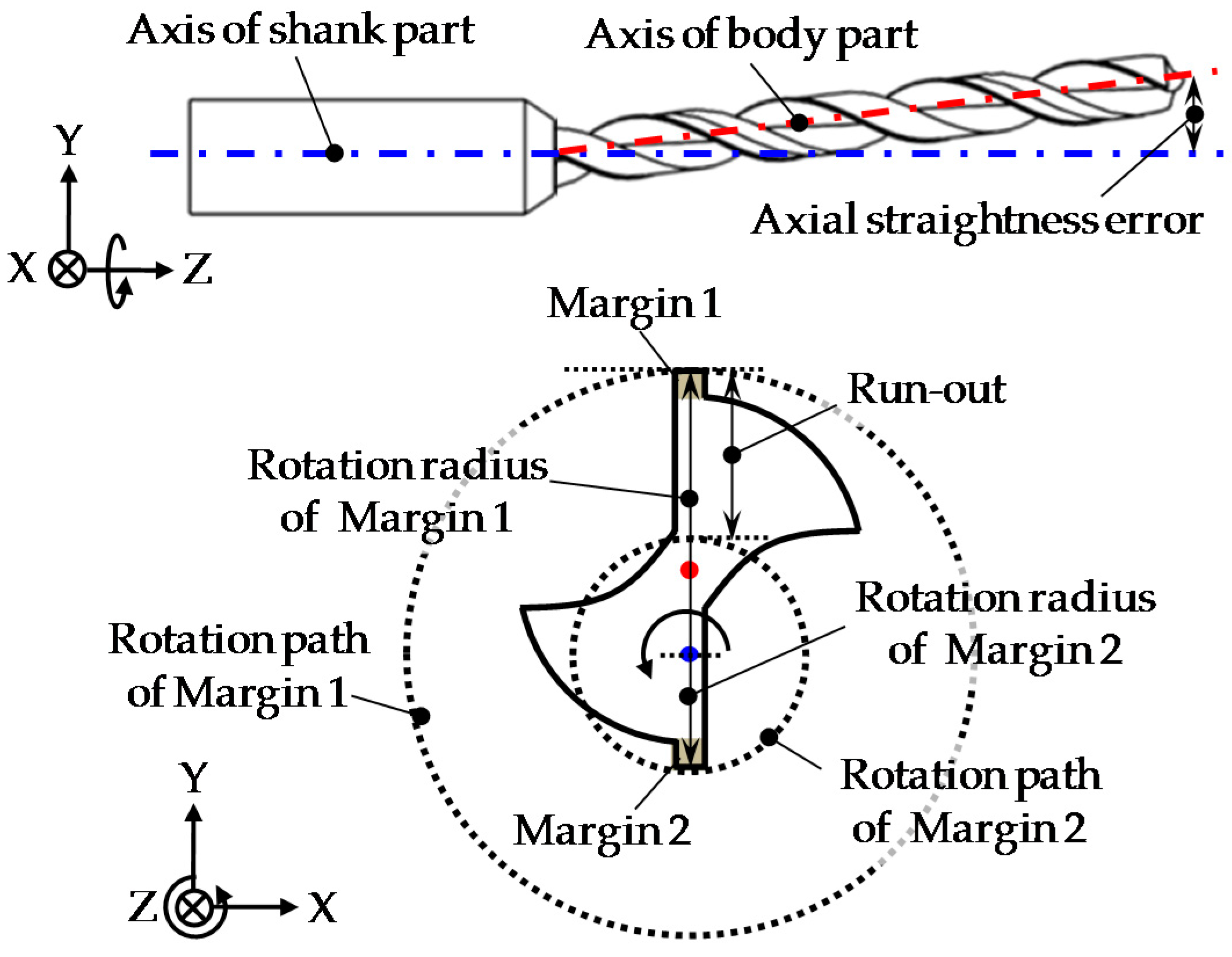
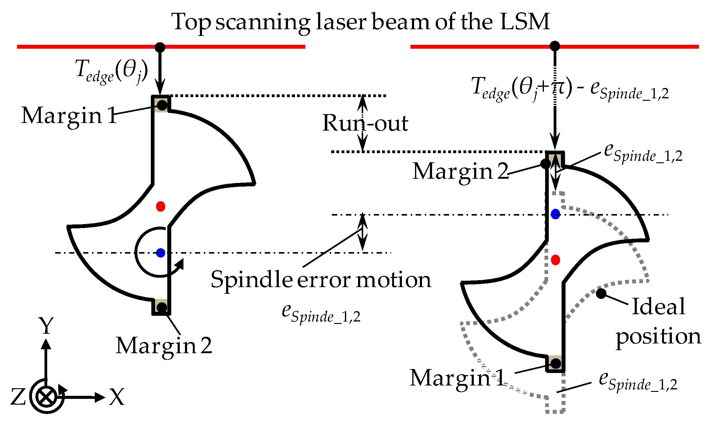
2.1. Principle of the Run-Out Measurement of the Microdrill Bit

Figure 4 shows the definition of the run-out of the microdrill bit. The axis straightness error between the body part and the shank part of the drill generates different distances from the axis of the shank part to two margins. The distance from the axis of the shank part to each margin is the rotation radius of each margin. When the microdrill bit is rotated, the rotation paths of the two margins are different. The run-out of the microdrill bit is thus defined to be the difference of the rotation paths of the two margins.
For the measurement of the run-out, the top edge segment of the LSM, which is referred to as TEdge(θ), is employed to measure the two margins. θ represents the angular position of the microdrill bit along its circumference. The measurement principle is shown in Figure 5. The microdrill bit is being rotated by the concentricity gauge, and the measurement output on Margin 1 is referred to as TEdge(θj), in which TEdge(θj) is the minimum measurement output of the top edge segment in the first half of the rotation of the microdrill bit. j is the sampling interval in the circumference direction. Hence, the measurement output on Margin 2 is referred to as TEdge(θj + π). Based on the definition, the run-out, which is the absolute value of the output difference on the two margins, can then be calculated as:
Run - out   =   | T Edge ( θ j )     T Edge ( θ j   +   π ) | ,
On the other hand, the spindle error motion of the concentricity gauge changes the height position (Y-direction) of the microdrill bit. This process is shown in Figure 6, in which the spindle error motion is t referred to as eSpindle_1,2. Then, the run-out influenced by eSpindle_1,2 can be written as:
Run - out   =   | T Edge ( θ j )   T Edge ( θ j   +   π ) + e Spindle _ 1 , 2 | ,
It can be seen from Equation (2) that the value of eSpindle_1,2 directly determines the measurement accuracy of the run-out. For achieving satisfied measurement accuracy, the spindle error motion of the concentricity gauge must be separated. As expressed above—that one revolution of the microdrill bit corresponds to a portion of one revolution of the concentricity gauge—the microdrill bit can be measured accurately at a fine position of the concentricity gauge, where the spindle error motion reaches the minimum. An accurate measurement of the spindle error motion of the concentricity gauge of the measurement system is a pre-condition in order to locate the fine position.

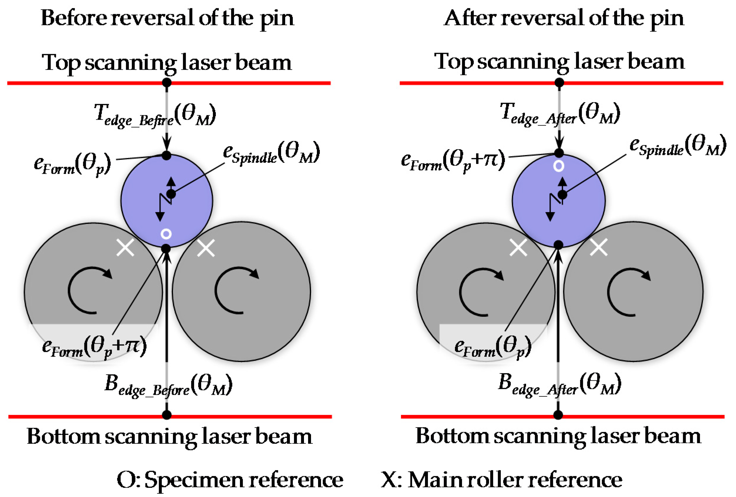
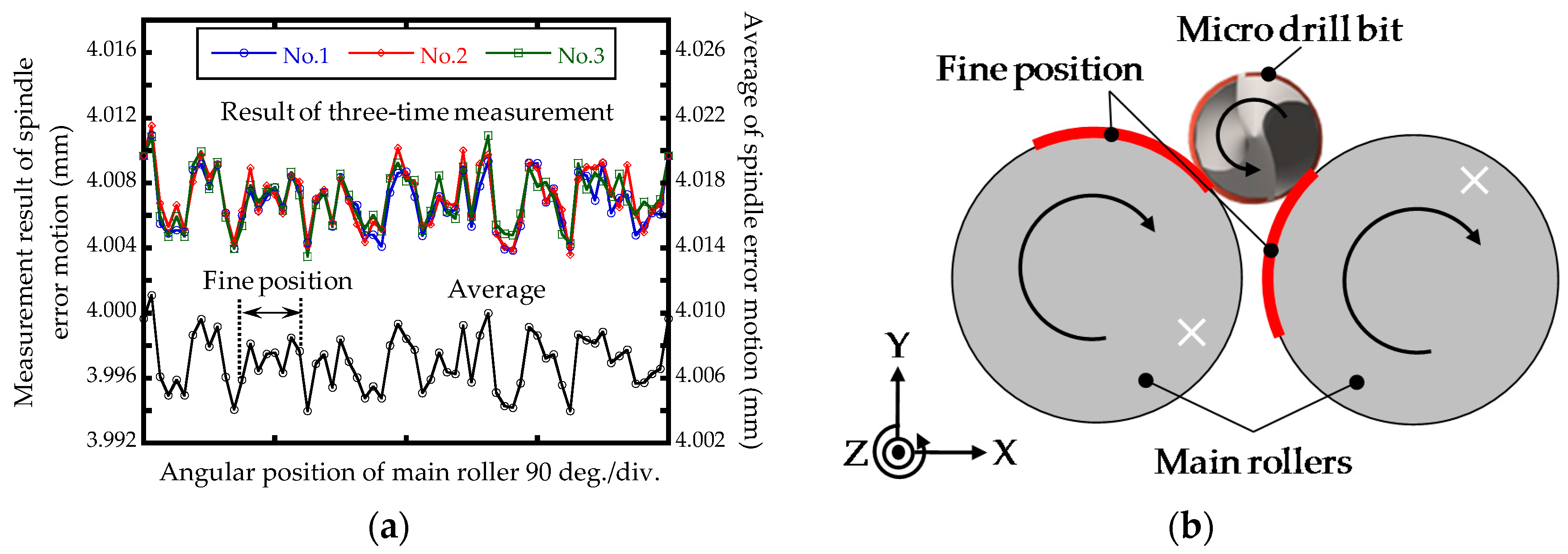
2.2. Spindle Error Motion Measurement Using the Laser Scan Micrometer

The reversal technique has been proposed for the measurement of the slide error motions and the spindle error motions of machine tools [20,21,22,23,24]. The measurement of the spindle error motion is usually performed with two displacement probes and a measurement artifact, in which the two displacement probes are arranged at two opposing sides of the artifact. To overcome the measurement error caused by the misalignment error of the two displacement probes, a large-diameter measurement artifact is frequently employed in practice for the measurement of the spindle error motion. However, the large-diameter measurement artifact cannot be used for the measurement of the spindle error motion of the concentricity gauge, due to its limited gripping capacity. In order to an achieve accurate measurement result of the spindle error motion of the concentricity gauge, instead of using two additional displacement probes, the top edge segment and the bottom edge segment of the LSM are employed to detect the two opposing sides of a measurement artifact with a small diameter for measurement of the spindle error motion. Since the linearity of the LSM over the whole measurement range has been well calibrated, the misalignment error of the top edge segment and the bottom edge segment is only on the level of 10 nm. Therefore, the misalignment-induced measurement error of the spindle error motion is negligible, even when employing the small-diameter measurement artifact.
A schematic of the spindle error motion measurement of the concentricity gauge by using the LSM is shown in Figure 7. The spindle error motion is referred to as eSpindle(θM). θM represents the angular position of the main rollers along its circumference, which is provided by the attached scale on the drive handle. A pin gauge with a small diameter is used as the measurement artifact. It is rotationally supported by the concentricity gauge. The upper surface and the lower surface of the pin gauge are simultaneously measured by the top edge segment and the bottom edge segment of the LSM, in which the top edge segment and the bottom edge segment are denoted as TEdge and BEdge, respectively. The spindle error motion of the concentricity gauge is measured before and after a 180-degree reversal operation of the pin gauge, as shown in Figure 8. Before the reversal operation of the pin gauge, the pin gauge is driven by the two main rollers, and the outputs of the top edge segment TEdge_Before and the bottom edge segment BEdge_Before are respectively expressed as:
T Edge _ Before ( θ M )   =   e Form ( θ p )   +   e Spindle ( θ M ) ,
B Edge _ Before ( θ M )   =   e Form ( θ p + π )   e Spindle ( θ M ) ,
where eForm(θp) is the form error of the pin gauge, including an out-of-roundness error component and a straightness error component. θp represents the angular position of the pin gauge along its circumference. After the pin gauge is rotated by 180 degrees with respect to the angular position of the two main rollers, the same measurement is conducted again, and the measurement outputs of the two edge segments are expressed as:
T Edge _ After ( θ M )   =   e Form ( θ p + π )   +   e Spindle ( θ d ) ,
B Edge _ After ( θ M )   =   e Form ( θ p )   e Spindle ( θ d ) ,
Based on the outputs of the two segment of the LSM before and after the reversal operation of the pin gauge, eSpindle(θM) can then be evaluated without the influence of eForm(θp) as:
e Spindle ( θ M )   =   1 4 [ T Edge _ Before ( θ M )   B Edge _ Before ( θ M )   +   T Edge _ After ( θ M ) B Edge _ Before ( θ M ) ] ,

3. Experiments

Measurement experiments of the spindle error motion of the concentricity gauge and the run-out of the microdrill bit were carried out based on the measurement setup in Figure 2. The concentricity gauge (Manufacturer: Universal Punch Corp., Santa Ana, CA, USA, Model: JSLP-10C) had two main rollers and a top roller. The diameters of the main rollers were 22 mm, and that of the top roller was 6.3 mm. A LSM (Manufacturer: Mitutoyo Corp., Kwasaki, Japan, Model: LSM-902/6900) had a scanning range of 32 mm, a resolution of 0.00001–0.01 mm (selectable), a linearity of ±0.03 μm (narrow scanning range), and a measurement speed of 800 cycles/second. The LSM had two average methods, which were the arithmetical average and the moving average, respectively, with an average range of 1–2048 points, which can be selectable in the instrument. The outputs of the LSM were recorded by a 64-bit PC through a RS-232 interface. Figure 9 shows a pin gauge and a microdrill bit, in which the pin gauge was employed as the measurement artifact for the measurement of the spindle error motion of the concentricity gauge, and the microdrill bit is the measurement target for the run-out measurement. The pin gauge had a diameter of 3 mm and a length of 50 mm. The diameter and the length of the shank part of the microdrill bit were 3 mm and 26 mm, and those of the body part of the microdrill bit were 0.75 mm and 24 mm, respectively.
The stabilities of the LSM measurement system were firstly investigated. The temperature during the measurement was measured as well by using a thermal sensor with a resolution of 0.001 °C. In the measurement of the stabilities, the LSM was set by using the moving average method, with averaging points of 512 to reduce the noise level. The measurement interval and the measurement resolution of the LSM were 0.64 s and 0.01 μm, respectively. The measurement of the stabilities lasted for one hour, while all of the parts of the LSM measurement system were kept stationary. The measurement result is shown in Figure 10. The peak-to-valley (PV) stabilities of the top edge segment and the bottom edge segment were evaluated as 0.57 μm and 0.65 μm, respectively, while the temperature drift during the measurement was characterized as 0.269 °C (PV). The stabilities of the measurement system were influenced by the mechanical stability between the concentricity gauge and the LSM, the drift of the scanning beam of the LSM, the temperature drift during the measurement procedure, etc.

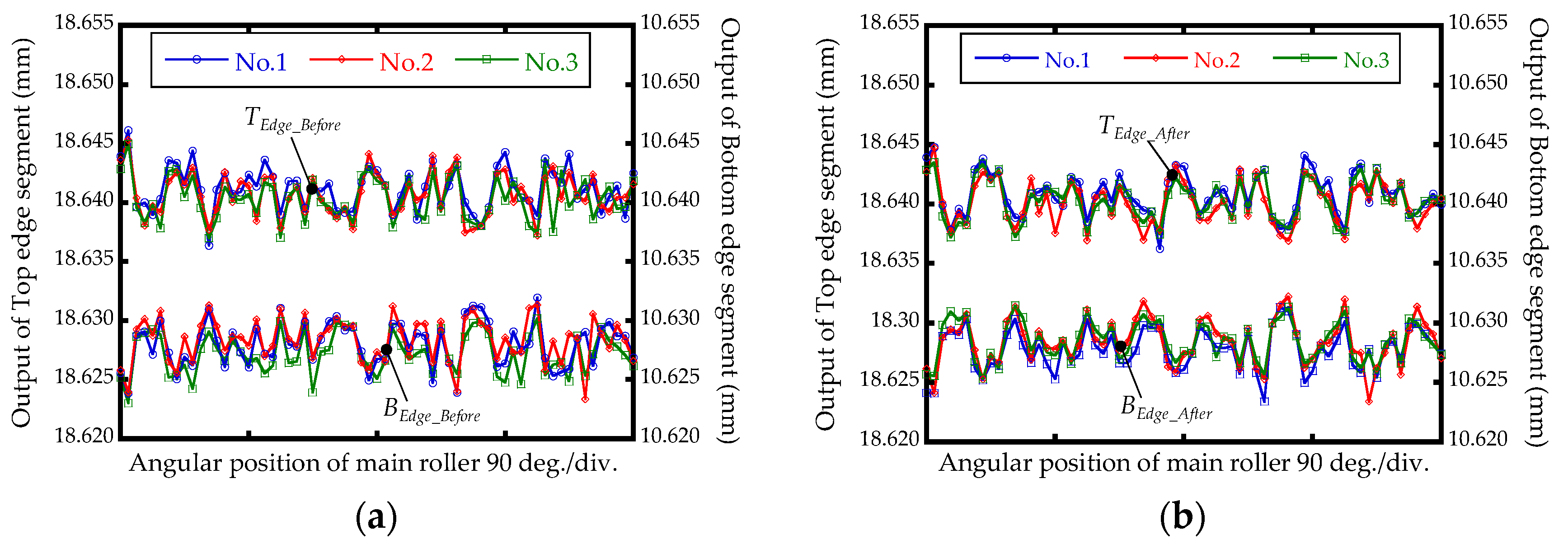
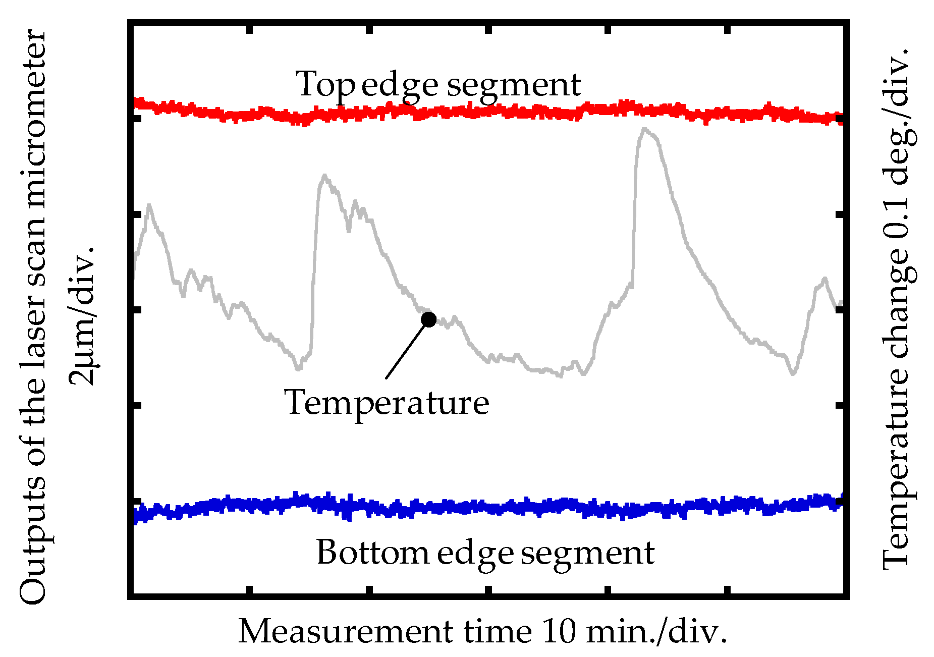
3.1. Experimental Result of the Spindle Error Motion Measurement

eSpindle(θM) of the concentricity gauge was evaluated based on the proposed measurement method, as shown in Figure 8. The concentricity gauge was driven manually, and the angular position was provided by the scale attached to the drive handle. The measurement sampling interval of eSpindle(θM) was 5.625°. The measurement of eSpindle(θM) was repeated by three revolutions, and the measurement outputs of TEdge and BEdge before and after the reversal operation are shown in Figure 11. Based on Equation (7), the measurement results of eSpindle(θM) were calculated, and are shown in Figure 12. The average PV value of eSpindle(θM) of the repeated measurement result was 7.10 μm, and the measurement repeatability was 2.54 μm. The repeatability error was mainly caused by the rotation accuracy of the concentricity gauge, since the concentricity gauge was driven manually. Also, the non-repeatable rotation errors of the two main rollers were also a factor that induced the repeatability error.
It can be seen from the measurement result that a fine position, which is located from the angular range of approximate 70° to 110°, had the minimum eSpindle(θM), which was 1.86 μm (PV). The fine position corresponds to a 0.111 revolution of the concentricity gauge. Since the diameter of the shank part of the microdrill bit and the diameter of the main rollers are 3 mm and 22 mm, one revolution of the microdrill bit corresponded to 0.136 revolution of the concentricity gauge. The range of the fine position of the concentricity gauge satisfied the required range for the measurement of the run-out of the microdrill bit.

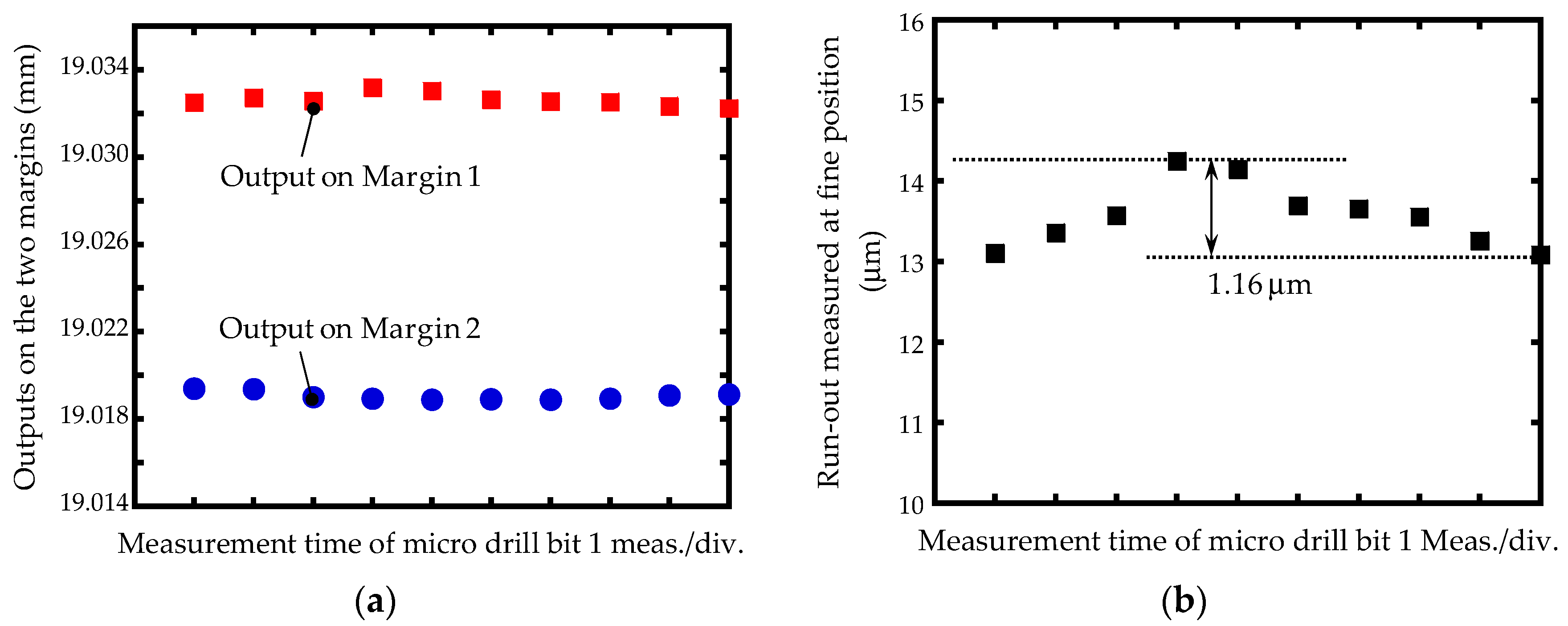
3.2. Experimental Result of the Run-Out Measurement

In order to separate eSpindle(θM) out of the concentricity gauge to meet the required measurement accuracy, the microdrill bit was measured at the identified fine position of the concentricity gauge. The microdrill bit was gripped at the beginning of the fine position of the concentricity, as shown in Figure 12b, and rotated one revolution to measure the two margins by the top segment of the LSM. Then, the microdrill bit was rotated back to the beginning of the fine position for the second measurement. This set of measurements was repeated 10 times, and the measurement outputs on the two margins are shown in Figure 13a. The measurement repeatability on Margin 1 and Margin 2 was 0.51 μm and 0.96 μm, respectively. By utilizing Equation (1) and the measurement outputs in Figure 13a, the average of the measured run-out of the microdrill bit was 13.57 μm, with a measurement repeatability of 1.16 μm, as shown in Figure 13b. The standard deviation of the measurement results was 0.40 μm. The repeatability error was mainly caused by the uneven rotational speed and the drift of the scanning beam of the LSM during the measurement.

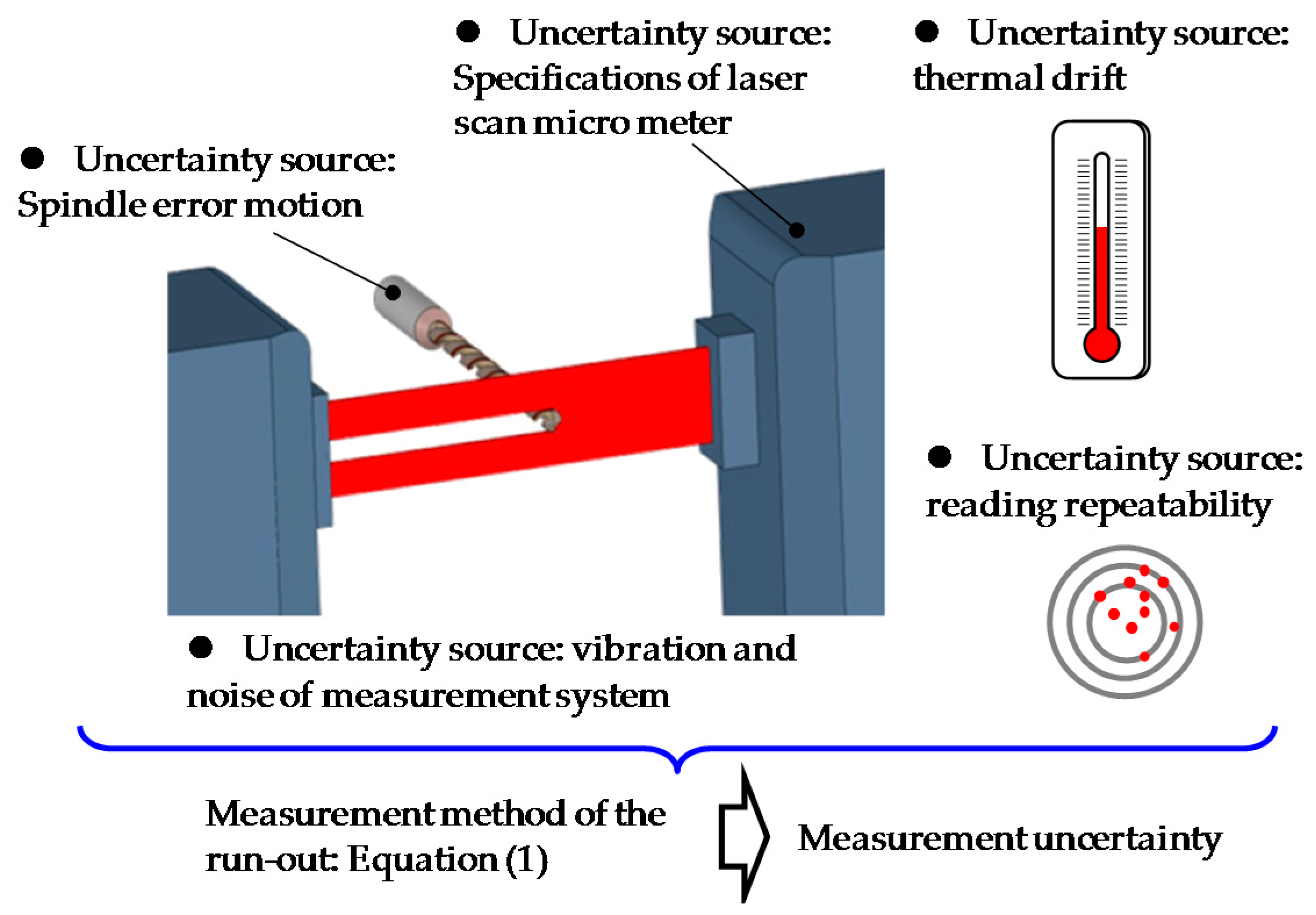
4. Uncertainty of the Run-Out Measurement

To confirm the reliability of the proposed methods for measurement of the run-out of the microdrill bit, an uncertainty evaluation of the measurement of the run-out was carried out based on Guide to Expression of Uncertainty in Measurement (GUM) [25]. Figure 14 shows a schematic of the uncertainty sources. The measurement uncertainty on each margin was composed of the measurement resolution of the LSM, the linearity of the LSM, the thermal drift, and the mechanical vibration during the measurement. The combined measurement uncertainty of each margin, which is referred to as uMargin, can be evaluated based on the following equation:
u Margin   =   u Resolution 2   +   u Linearity 2   +   u Thermal 2   +   u Vibration 2 ,
According to Equation (2), the measurement uncertainty of the run-out was composed of the uMargin of the two margins and the uncertainty uSpindle of the spindle error motion of the concentricity gauge, as well as the uncertainty uReading of the measurement repeatability of the run-out, in which uSpindle is the spindle error motion at the fine position of the concentricity gauge. The combined measurement uncertainty of the run-out, which is referred to as uRun-out, can be expressed as:
u Run - out   =   2 u Margin 2   +   u Spindle 2   +   u Reading 2 ,
Table 1 shows the uncertainty budget for the measurement of the run-out. uMargin was evaluated to be 0.34 μm. The combined uncertainty of uRun-out based on Equation (9) was evaluated to be 0.61 μm. The expanded uncertainty with a coverage factor of k = 2 for the measurements of the run-out was evaluated to be 1.22 μm, in which the evaluated uncertainty had a level of confidence of approximately 95%. The measurement results and the measurement uncertainty confirmed that the proposed error separation method is reliable for the measurement of the run-out with sub-micrometric accuracy.
Compared with the previous research studies that used ultra-precision rotary drive devices, the proposed error separation method can also achieve sub-micrometric accuracy for the measurement of the run-out of microdrill bit, even though the spindle error motion of the concentricity gauge was as large as 7.10 μm. Although the realized accuracy has been sufficient for industrial application, from the uncertainty budget, it can be seen that the spindle error motion of the fine position of the concentricity gauge was still the major source contributing to the measurement uncertainty. For improving the measurement accuracy to the nanometric order, it is necessary to further separate the spindle error motion, which remains as the next step of the research.

5. Conclusions

An error separation method has been proposed for a precision measurement of the run-out of a microdrill bit by using a measurement system consisting of a concentricity gauge and a laser scan micrometer (LSM). In order to achieve a precision measurement of the run-out, rotating the microdrill bit at the fine position of the concentricity gauge with the minimum spindle error motion for the measurement of the run-out was proposed for separating the influence of the spindle error motion. Taking into consideration the limited gripping capacity of the concentricity gauge, the LSM and a small-diameter artifact—instead of the conventionally used displacement probes and large-diameter artifact—were employed to measure the spindle error motion of the concentricity gauge for determining the fine position. Then, the measurement of the run-out was conducted at the determined fine position to achieve high measurement accuracy, which previously cannot be realized by the commercial concentricity gauge combined LSM measurement system.
The measurement result showed that the average of the measured run-out was 13.57 μm. The measurement uncertainty of the run-out by using the measurement system and the proposed error separation method was estimated to be 0.61 μm. It has been confirmed that the proposed error separation method is reliable for a run-out measurement with sub-micrometric measurement accuracy. As the first step of the research, this paper has focused on achieving the precision measurement of the run-out. It should be noted that the measurement position along the axial direction of the microdrill bit hasn’t been accurately determined in this research. Instead, an additional positioning stage is necessary to determine the axial measurement position on the microdrill bit, which will be carried out as next step of this research.

Author Contributions

Z.N. conducted experiments and paper writing. Y.-L.C., Y.S., H.M. and W.G. designed the study, supervised the work and modified the manuscript.

Conflicts of Interest

The authors declare no conflict of interest.

References

  1. LaDou, J. Printed circuit board industry. Int. J. Hyg. Environ. Health 2006, 209, 211–219. [Google Scholar] [CrossRef] [PubMed]
  2. Nguyen, N.T.; Huang, X. Miniature valveless pumps based on printed circuit board technique. Sens. Actuators A Phys. 2001, 88, 104–111. [Google Scholar] [CrossRef]
  3. Gower, M.C. Industrial applications of laser micromachining. Opt. Express 2000, 7, 56–67. [Google Scholar] [CrossRef]
  4. Gan, E.K.; Zheng, H.Y.; Lim, G.C. Laser drilling of micro-vias in PCB substrates. In Proceedings of the 3rd Electronics Packaging Technology Conference (EPTC 2000), Sheraton Towers, Singapore, 5–7 December 2000. [Google Scholar]
  5. Sen, M.; Shan, H.S. A review of electrochemical macro-to micro-hole drilling processes. Int. J. Mach. Tools Manuf. 2005, 45, 137–152. [Google Scholar] [CrossRef]
  6. Rajurkar, K.P.; Sundaram, M.M.; Malshe, A.P. Review of electrochemical and electrodischarge machining. Procedia CIRP 2013, 6, 13–26. [Google Scholar] [CrossRef]
  7. Cheong, M.S.; Cho, D.W.; Ehmann, K.F. Identification and control for micro-drilling productivity enhancement. Int. J. Mach. Tools Manuf. 1999, 39, 1539–1561. [Google Scholar] [CrossRef]
  8. Yoon, H.S.; Wu, R.; Lee, T.M.; Ahn, S.H. Geometric optimization of micro drills using Taguchi methods and response surface methodology. Int. J. Precis. Eng. Manuf. 2011, 12, 871–875. [Google Scholar] [CrossRef]
  9. Chyan, H.C.; Ehmann, K.F. Development of curved helical micro-drill point technology for micro-hole drilling. Mechatronics 1998, 8, 337–358. [Google Scholar] [CrossRef]
  10. Fu, L.; Guo, Q. Development of an ultra-small micro drill bit for packaging substrates. Circuit World 2010, 36, 23–27. [Google Scholar] [CrossRef]
  11. Wang, X.; Wang, L.J.; Tao, J.P. Investigation on thrust in vibration drilling of fiber-reinforced plastics. J. Mater. Process. Technol. 2004, 148, 239–244. [Google Scholar] [CrossRef]
  12. Fu, L.; Li, X.; Guo, Q. Development of a micro drill bit with a high aspect ratio. Circuit World 2010, 36, 30–34. [Google Scholar] [CrossRef]
  13. Ancău, M. The optimization of printed circuit board manufacturing by improving the drilling process productivity. Comput. Ind. Eng. 2008, 55, 279–294. [Google Scholar] [CrossRef]
  14. Bhandari, B.; Hong, Y.S.; Yoon, H.S.; Moon, J.S.; Pham, M.Q.; Lee, G.B.; Huang, Y.; Linke, B.S.; Dornfeld, D.A.; Ahn, S.H. Development of a micro-drilling burr-control chart for PCB drilling. Precis. Eng. 2014, 38, 221–229. [Google Scholar] [CrossRef]
  15. Huang, C.K.; Wang, L.G.; Tang, H.C.; Tarng, Y.S. Automatic laser inspection of outer diameter, run-out and taper of micro-drills. J. Mater. Process. Technol. 2006, 171, 306–313. [Google Scholar] [CrossRef]
  16. Watanabe, H.; Tsuzaka, H.; Masuda, M. Microdrilling for printed circuit boards (PCBs)—influence of radial run-out of microdrills on hole quality. Precis. Eng. 2008, 32, 329–335. [Google Scholar] [CrossRef]
  17. Suganthi, X.H.; Natarajan, U.; Ramasubbu, N. A review of accuracy enhancement in microdrilling operations. Int. J. Adv. Manuf. Technol. 2015, 81, 199–217. [Google Scholar] [CrossRef]
  18. Williams, K.L. Concentricity Gage. U.S. Patent 4,679,330, 14 July 1987. [Google Scholar]
  19. Laser Scan Micrometer-Mitutoyo. Available online: http://www.mitutoyo.com/wp-content/uploads/2013/07/2101_Laser-Scan-Mic.pdf (accessed on 5 October 2017).
  20. Evans, C.J.; Hocken, R.J.; Estler, W.T. Self-calibration: Reversal, redundancy, error separation, and ‘absolute testing’. CIRP Ann.-Manuf. Technol. 1996, 45, 617–634. [Google Scholar] [CrossRef]
  21. Gao, W.; Lee, J.C.; Arai, Y.; Noh, Y.J.; Hwang, J.H.; Park, C.H. Measurement of slide error of an ultra-precision diamond turning machine by using a rotating cylinder workpiece. Int. J. Mach. Tools Manuf. 2010, 50, 404–410. [Google Scholar] [CrossRef]
  22. Lee, J.; Gao, W.; Shimizu, Y.; Hwang, J.; Oh, J.S.; Park, C.H. Spindle error motion measurement of a large precision roll lathe. Int. J. Precis. Eng. Manuf. 2012, 13, 861–867. [Google Scholar] [CrossRef]
  23. Niu, Z.; Chen, Y.L.; Matsuura, D.; Lee, J.C.; Kobayashi, R.; Shimizu, Y.; Ito, S.; Wei, G.; Oh, J.S.; Park, C.H. Precision measurement of Z-slide vertical error motion of an ultra-precision lathe by using three-probe method. Int. J. Precis. Eng. Manuf. 2017, 18, 651–660. [Google Scholar] [CrossRef]
  24. Chen, Y.L.; Niu, Z.; Matsuura, D.; Lee, J.C.; Shimizu, Y.; Gao, W.; Oh, J.S.; Park, C.H. Implementation and verification of a four-probe motion error measurement system for a large-scale roll lathe used in hybrid manufacturing. Meas. Sci. Technol. 2017, 28. [Google Scholar] [CrossRef]
  25. BIPM; IEC; IFCC; ILAC; ISO; IUPAC; IUPAP; OIML. Evaluation of Measurement Data—Guide for the Expression of Uncertainty in Measurement (GUM); International Bureau of Weight and Measures: Sèvres, France, 2008. [Google Scholar]
Figure 1. Axial straightness error of the microdrill bit.
Jmmp 02 00004 g001
Figure 2. (a) Photographs and (b) schematic of the laser scan micrometer measurement system.
Jmmp 02 00004 g002aJmmp 02 00004 g002b
Figure 3. Measurement principle of laser scan micrometer (LSM).
Jmmp 02 00004 g003
Figure 4. Definition of the run-out.
Jmmp 02 00004 g004
Figure 5. Measurement principle of the run-out.
Jmmp 02 00004 g005
Figure 6. Influence of the spindle error motion on the run-out measurement.
Jmmp 02 00004 g006
Figure 7. Schematic of the measurement of the spindle error motion of concentricity gauge.
Jmmp 02 00004 g007
Figure 8. Measurement principle of the spindle error motion.
Jmmp 02 00004 g008
Figure 9. Photographs of (a) the pin gauge and (b) the microdrill bit.
Jmmp 02 00004 g009
Figure 10. Stability of the laser scan micrometer measurement system.
Jmmp 02 00004 g010
Figure 11. Measurement outputs (a) before and (b) after reversing the pin gauge.
Jmmp 02 00004 g011
Figure 12. (a) Measurement result of the spindle error motion and (b) the fine position for the run-out measurement.
Jmmp 02 00004 g012
Figure 13. (a) Measurement outputs on the two margins and (b) the measurement result of the run-out at the fine position of the concentricity gauge.
Jmmp 02 00004 g013
Figure 14. Schematic of the uncertainty sources of the run-out measurement.
Jmmp 02 00004 g014
Table 1. Uncertainty budget of the run-out measurement.
Uncertainty SourceTypeStandard Uncertainty (μm)
LSMResolutionB2.89 × 10−4
LinearityB0.02
Thermal driftB0.16
Mechanical vibrationA0.04
Combined uncertainty uMargin 0.17
Spindle error motionB0.54
Reading repeatabilityA0.13
Combined uncertainty uRun-out 0.61

