1. Introduction
Combining welding processes have been used since the 1970s. This combination has come to be called hybrid welding, which is a technology that consists of combining different types of welding processes, which operate simultaneously in the same weld puddle, i.e., a new process should result from the combination of two (or more) conventional processes in which the new process offers the effects of which each process individually is incapable. According to Messler [
1], this type of process arose from the need to have energy sources, which would have a greater capacity, thereby increasing productivity. Since then, many studies have been conducted that combine processes such as those that use electric arc, electron beam, light amplification by stimulated emission of radiation (LASER) and friction.
Most hybrid welding studies concentrate on combining LASER with some kind of electric arc process, such as: LASER associated with the tungsten inert gas (TIG) [
2,
3]; LASER with metal inert gas (MIG) or metal active gas (MAG) [
4,
5,
6,
7]; LASER with plasma arc welding (PAW); and other configurations. In these cases, different types of LASER (CO
2, Nd-YAG, etc.) are used. Moreover, combinations between electric arc processes are used such as PAW with MIG/MAG [
8,
9,
10] and TIG with MIG/MAG. According to Kanemaru [
11], the latter has become a low-cost alternative because the equipment for electric arc welding, compared to that for LASERs, is less expensive.
For Kanemaru [
12], the TIG-MIG/MAG hybrid welding process—also known as gas tungsten arc welding (GTAW)/gas metal arc welding (GMAW)—consists of combining the TIG and MIG/MAG processes in a single welding process. This process usually works by using a TIG welding torch running through the workpiece, which leads to the melt pool, i.e., at the front of the MIG/MAG torch, which heats and forms a keyhole in the source material. Subsequently, the MIG/MAG surges and follows the process by filling in the “keyhole” created by the TIG process and adds material because an electric arc and an electrode wire are used. Briefly, the process consists of a TIG arc warming and opening a gap in the workpiece so as to have a deep penetration, while the MIG/MAG process deposits material in a highly efficient way, thereby completing the process.
Dykhno, Davis [
13] and Meng [
14] state that TIG-MIG/MAG hybrid welding, relative to conventional processes, can double the performance because it increases the penetration of the weld, offers greater control over the heat-affected zone and increases the speed of welding, which together characterizes increased productivity.
Recently, some studies have been carried out with the TIG-MIG/MAG hybrid welding process. For example, Teixeira [
15] studied the effects of parameters on the weld bead geometry for the TIG and MAG process in tandem and conventional MAG. However, the final results indicated a difference when using a TIG torch to preheat the base material, but statistically, this difference was not significant between TIG and MAG processes in tandem and conventional MAG for the range of welding parameters adopted. Kanemaru et al. [
11,
12] analyzed the influence of parameters (TIG and MIG electric current, the angle between welding torches and the distance between torches) on arc stability and weld bead geometry (the penetration of the weld, the ratio between bead width and bead height). In this analysis, Kanemaru et al. [
11,
12] reached the following conclusions: the TIG electric current must be greater than the MIG electric current in order to have a significant influence on the penetration of the weld, and they observed that TIG electrical currents of less than 300 A kept the penetration of the weld practically constant; on increasing the distance between the welding torches, the electric arc becomes unstable; and the variation of the angles between the welding torches did not show a notable variation in the weld bead geometry (width and bead height). Chen et al. [
16] and Mishima et al. [
17] developed numerical simulations of the TIG-MIG/MAG hybrid welding process so as to analyze the thermal behavior of the welded joints. The numerical simulation showed that there is the possibility of optimizing the concentration of heat generated by the electric arcs by adjusting the angle between the TIG and MIG torches.
On the other hand, Chen et al. [
16] presented an improvement in the models of sources of heat for the TIG/MIG hybrid process, but did not consider the interaction between the arcs. Meng et al. [
14] proposed a TIG/MAG hybrid welding process with high welding speeds, for which they analyzed the influence of the parameters (TIG and MAG electrical currents, voltage, etc.) on: the welding speed, the mechanical properties and the appearance of the weld bead. According to Meng et al. [
14], the mechanical properties of joints soldered by the conventional MAG process and the welding speed can be increased as the electric current TIG increases.
The TIG/MIG-MAG hybrid welding process has been used when welding dissimilar materials according to studies by Ding et al. [
18] and Zhang et al. [
19]. A microstructural analysis of the welding of ferritic stainless steels with magnesium alloys was performed by Ding et al. [
18], in which they show that the hybrid welding process was efficient at producing joints with dissimilar materials. Zhang et al. [
19] welded-brazed stainless steels with aluminum by using a different configuration of the hybrid TIG/MIG process, i.e., the MIG torch was positioned on the top of the workpiece and the TIG torch on the bottom of the workpiece (MIG-TIG double-sided).
Some authors [
20,
21,
22,
23,
24] have optimized the hybrid welding process in relation to weld bead geometry and other properties. However, no specific study on optimizing the TIG-MIG/MAG hybrid process was found. Thus, this article sets out to determine the influence of the TIG/MIG-MAG hybrid welding parameters (factors) on weld bead geometry and to optimize the factors by seeking the best weld bead geometries through the Taguchi statistical method. The Taguchi method is one of the optimization techniques that could be applied to optimize input welding parameters. Optimization of process parameters is the key step in the Taguchi method in achieving high quality without increasing the cost. This is because optimization of process parameters can improve performance characteristics. The optimal process parameters obtained from the Taguchi method are insensitive to the variation of environmental conditions and other noise factors [
20].
2. Materials and Methods
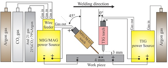
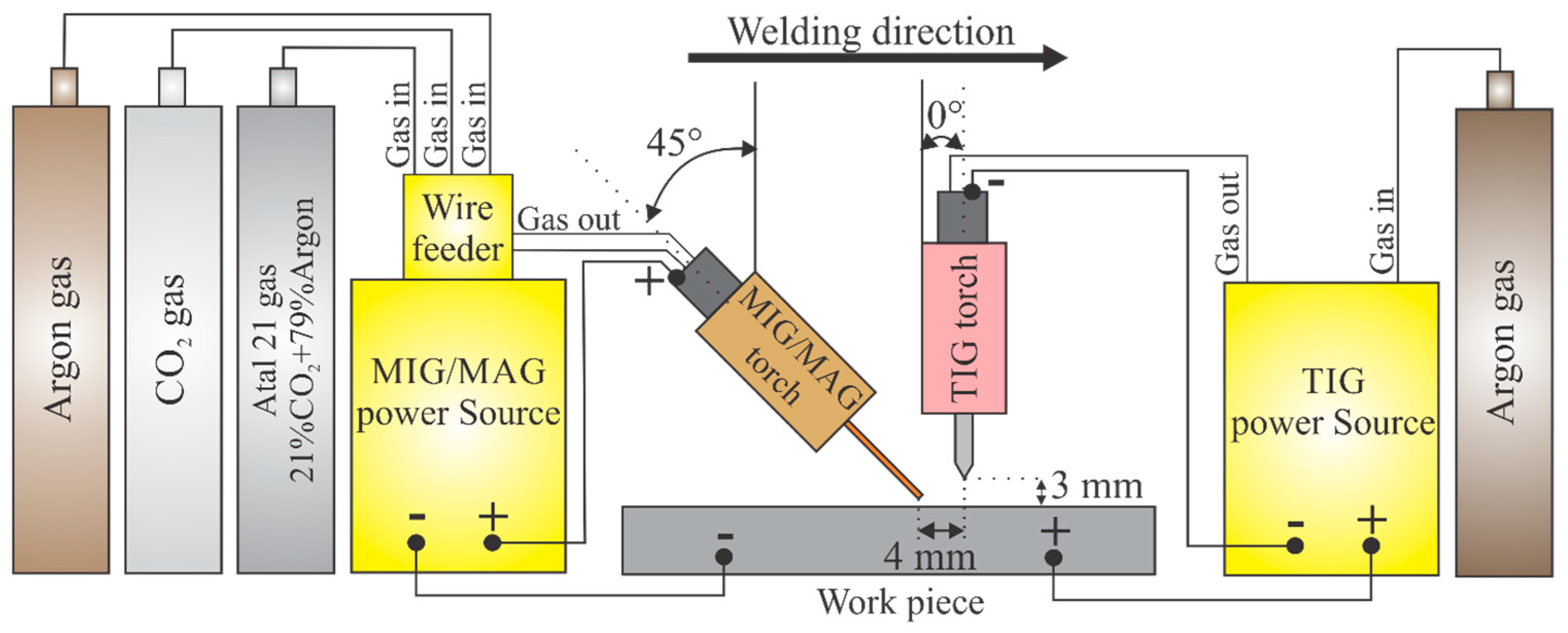
Figure 1 illustrates the experimental system used for the hybrid welding of test specimens. This system consists of a ESAB TIG 2200i AC/DC (ESAB-Brazil, Contagem, Minas Gerais, Brazil) welding source with a high frequency drive, a ESAB MIG/MAG Warrior 500i DC/CV (ESAB-Brazil, Contagem, Minas Gerais, Brazil) welding source with automatic wire feed, a table with automated displacement and the gas cylinders used (argon, CO
2 and Atal 21 – gas mixture of 21% CO
2 + 79% Ar). For the TIG welding process, an AWS EWTh-2 electrode which was 2.4 mm in diameter and had a 60° apex angle was used. The polarity used in the TIG process was DCNE (Direct Current Negative Electrode), that is continuous electric current with a negative electrode. The position of the TIG torch was 0° to the vertical. The distance from the tip of the electrode to the workpiece was 3 mm, that is the length of the electric arc was 3 mm. For MIG/MAG welding, an AWS ER70S-6 wire 1 mm in diameter was used. The polarity used in the MIG/MAG process was DCPE, that is a continuous electric current with a positive electrode. The inclination of the torch in relation to the vertical was 45°. The distance between the contact tip and the workpiece was 10 mm, and the distance between the electrode (TIG) and the wire (MIG/MAG) was 4 mm.
In this welding system, the welding sources were driven simultaneously, i.e., the electric, TIG and MIG/MAG arcs were started at the same moment by means of an on/off switch. Furthermore, in this system, the welding torches remained fixed, and the table moved automatically.
The test specimens were made of AISI 1045 steel, 8 mm thick, 38 mm wide and 200 mm long, for which bead-on-plate welding was used.
Design of Experiments
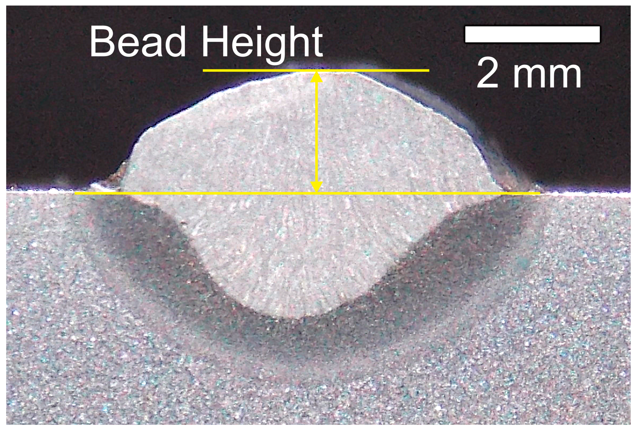
What was initially defined were the characteristics of the weld bead geometry that would be analyzed. Thus, the study of the following output variables (responses) was set: weld penetration, the heat-affected zone (HAZ), weld width and weld height. The desired characteristics consisted of obtaining greater penetration and less bead height. For the weld width, optimization was planned for a larger width due to a possible use in surface coating processes, whereas for the HAZ the smallest area was desired.
Based on a theoretical grounding, the factors that would be varied in this study were defined. The factors chosen were: the gas type (MIG/MAG), voltage (MIG/MAG), wire feed (MIG/MAG), electric current (TIG), gas flow rate (TIG) and welding speed.
In order to define the three levels that would be varied in each welding parameter, initial tests were performed with the TIG and MIG/MAG welds, individually.
Table 1 shows the experimental matrix with the order of the experiments and respective values for each welding parameter.
The other factors were kept constant, such as: argon as gas type (TIG); MIG/MAG shielding gas flow of 12.5 L/min; direction of welding; MIG/MAG torch angle of 45°; position of the TIG torch perpendicular to the workpiece; a distance of 3 mm from the TIG electrode to the workpiece; a distance of 10 mm from the MIG/MAG contact tip to the workpiece; and a distance of 4 mm between the electrode (TIG) and wire (MIG/MAG). The average MIG/MAG electric current intensity varied with the wire feed, i.e., for the wire feeds of 7 m/min, 8 m/min and 9 m/min, the MIG/MAG average electric current intensity were 170 A, 190 A and 210 A, respectively.
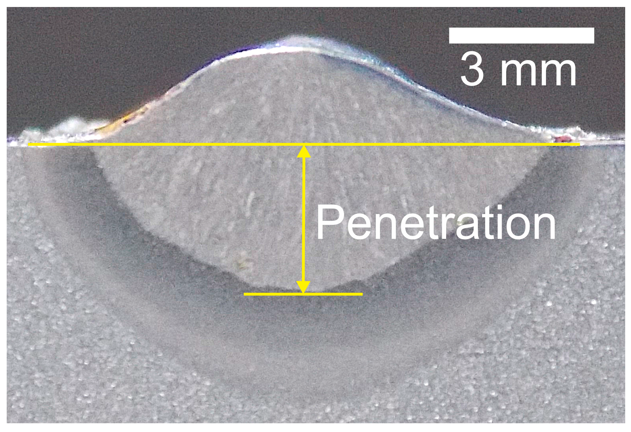
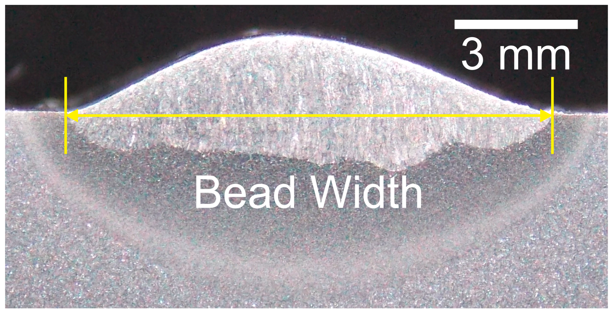
The geometry of the weld beads was analyzed using macrography, which was performed by separating, sanding and polishing the specimens. The macrograph was developed using chemical etching with 5% nital. The images of the macrographs were captured with a photographic camera. The weld geometry (penetration, bead width, bead height and HAZ estimated) was measured using ImageJ software.
Variance analysis was performed to determine the influence of the factors on the output variables, in which the influences of factors that had a p-value equal to or less than 0.05 (considered to be a critical value) were considered reliable, which indicates a degree of certainty equal to or above 95% in relation to what is being affirmed. The results were validated by performing the welding process again with the factors that were considered ideal. The signal/noise (S/N) ratio was used for optimization of the variables responses.
3. Results
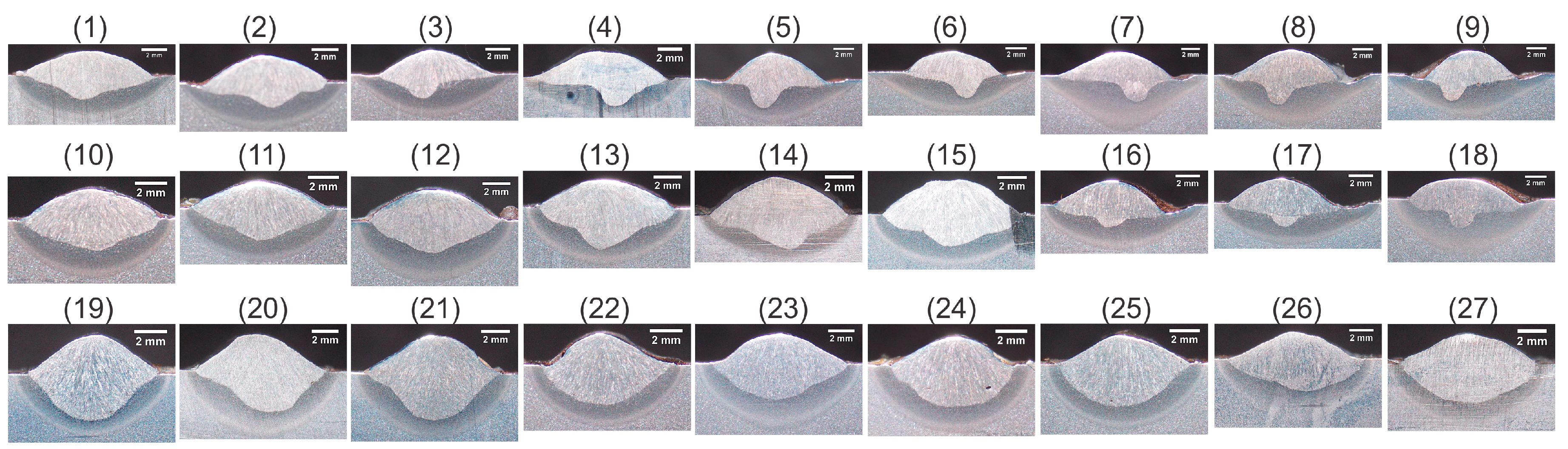
Figure 2 shows 27 macrographs out of 81 made to determine the dimensions of the weld bead. Macrographs follow the sequence of the experiments listed in
Table 1, and the effect of the welding parameters (factors) on the weld bead geometry can be observed. The mean values obtained in the experiments for responses are presented in
Table 2.
The presentation of the results is divided into four stages: an analysis of the penetration, the HAZ, the bead width and the bead height.
3.1. Weld Penetration
Using the analysis of variance, presented in
Table 3, it can be affirmed with a 95% degree of certainty that the factors that significantly influenced the penetration of the weld were the type of shielding gas (MIG/MAG), the voltage (MIG/MAG), the wire feed speed (MIG/MAG) and the welding speed. The order of factors that most affected the penetration, measured from the
f-values, consists of the wire feed rate (MIG/MAG), the type of shielding gas (MIG/MAG), voltage (MIG/MAG) and the welding speed, respectively. As for gas flow (TIG) and the electric current intensity (TIG), the influence of these factors on the penetration of the solder cannot be affirmed, with 95% significance. In other words, to analyze the influence of these factors, other studies should be undertaken by changing, for example, the levels of the items. Furthermore, according to Kanemaru et al. [
11], the TIG electric current values should be higher than the MIG/MAG electric current values so as to obtain the influence of the TIG electric current on the penetration.
In order to visualize better the behavior of the penetration of the solder in relation to the factors,
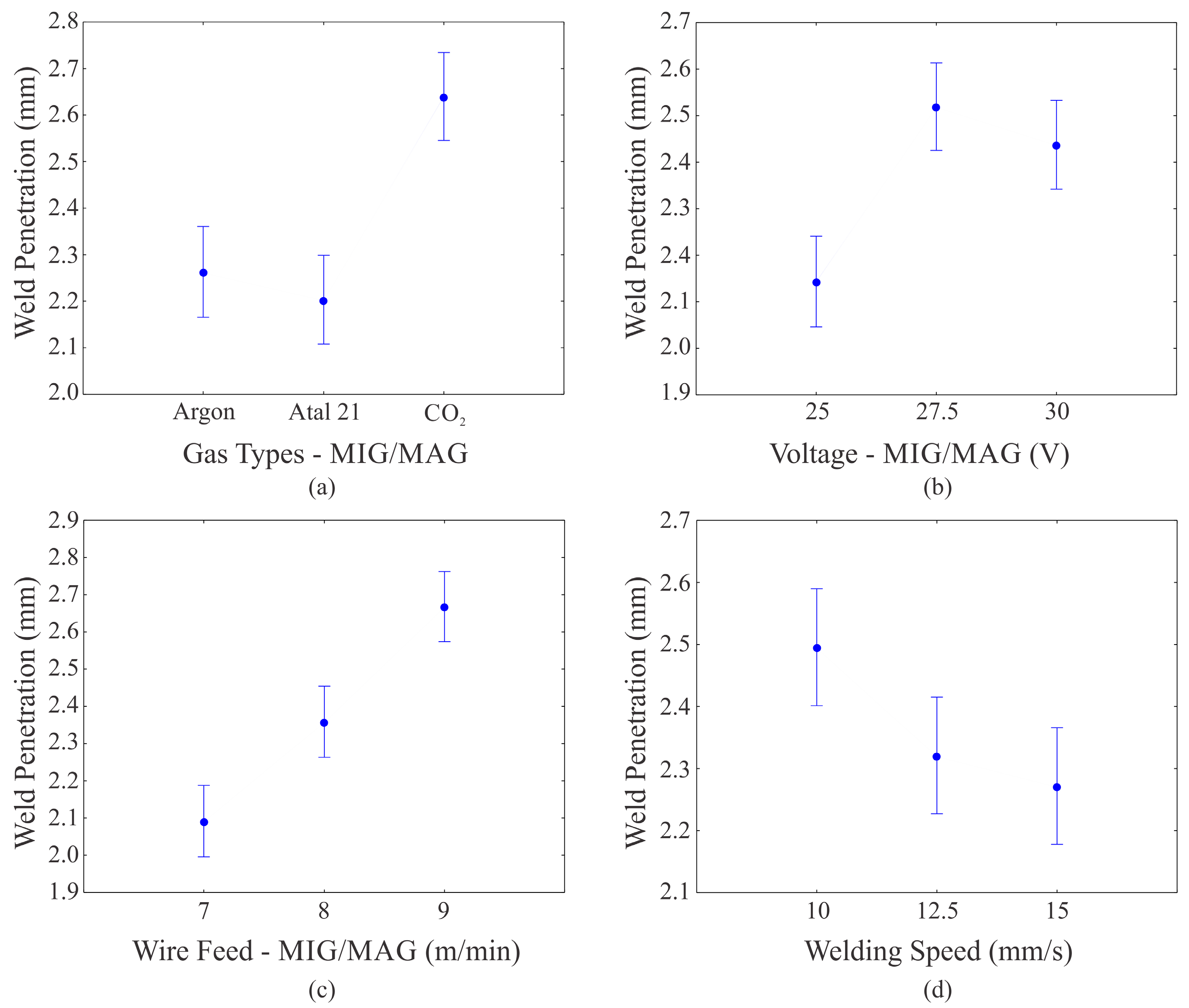
Figure 3 shows graphs of the penetration of the average weld because of the factors that had a significant influence.
Figure 3a shows the graph of penetration due to the type of shielding gas (MIG/MAG), where it is observed that the tendency is that the highest penetration values are obtained using CO
2 as the shielding gas. The lowest penetrations are the result of the mixture of CO
2 with argon (Atal 21).
Figure 3b graphically shows the relationship between the MIG/MAG voltage and the penetration. For this factor, what is highlighted is that, on average, the smallest penetrations were obtained with the lowest voltage, while the largest resulted from an intermediate level of voltage. Penetration increased significantly when the (MIG/MAG) wire feed speed was increased, as can be seen in
Figure 3c, the highest penetration values being obtained with the highest feed speed of the wire.
Figure 3d shows that an increase in the welding speed implies that penetration is reduced, which indicates that the greatest penetrations tend to be obtained using the lowest level of welding speed.
The behavior of penetration in relation to the type of shielding gas (MIG/MAG) was in accordance with the literature [
25], the use of CO
2 tending to have a greater penetration in relation to the other gases due the high oxidation potential and high thermal conductivity of the CO
2. The wire-feed speed (MIG/MAG) and the welding speed followed the trend that increasing the first or decreasing the second increases the penetration. Penetration increases with increasing the MIG/MAG wire feed due to increased MIG/MAG electrical current and consequently increasing welding energy. Furthermore, larger electric currents result in droplets with higher velocities, which may contribute, by momentum, to greater penetration. Already the increase of the welding speed decreases the welding energy and consequently decreases the penetration [
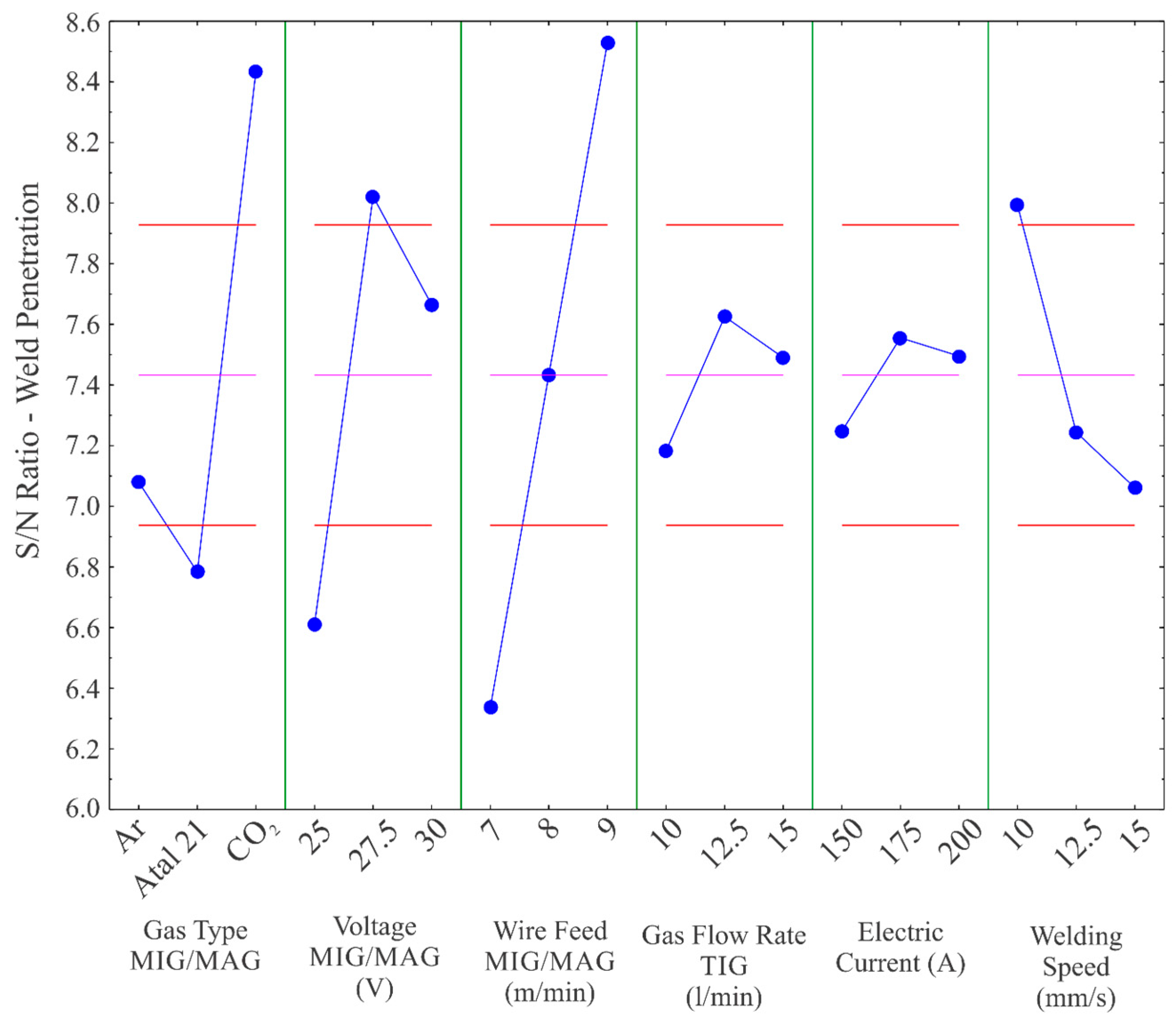
10]. The voltage (MIG/MAG) tends to present more influences on other factors, such as the width. However, this influence of the voltage on the penetration may be a characteristic of this hybrid welding process, because the increase of the MIG/MAG arc voltage along with the electric arc length generates an increase of the bead width and a decrease of the bead height, besides the reduction of the penetration. Possibly, the increase of the penetration with the increase of the arc voltage MIG/MAG for the interval 25 V–27.5 V may have occurred due to the greater stability of the arc generated by the electric arc TIG in the hybrid process. Optimizing the process consisted of maximizing the penetration of the weld. The graph of the S/N ratio bigger is better, as per
Figure 4, where the ideal levels of factors are those with the highest S/N ratio. Note that optimizing the penetration of the solder consists of using CO
2 as the shielding gas (MIG/MAG), a voltage (MIG/MAG) of 27.5 V, a value of 9 m/min for the wire feed (MIG/MAG), a flow of the shielding gas (TIG) and the intensity of the electric current (TIG) with 12.5 L/min and 175 A, respectively, and a welding speed of 10 mm/s. These values indicated by the S/N ratio maximize the penetration because the welds carried out with these values presented greater penetration.
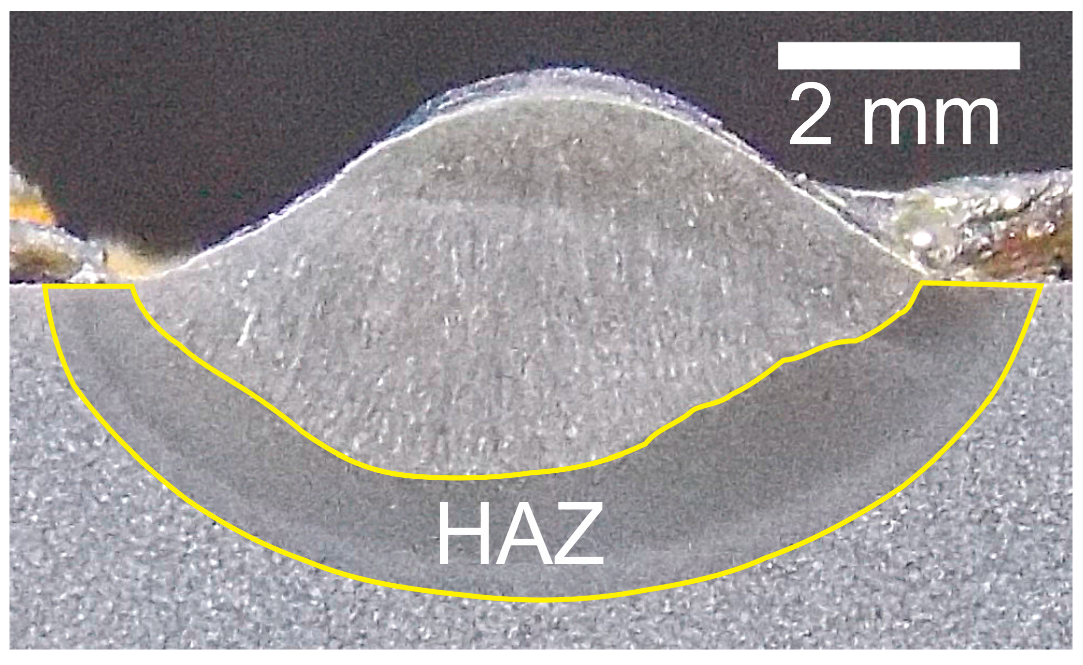
To confirm the optimization, a test piece was welded with the factors indicated. The analysis confirmed optimization, a penetration of 2.96 mm being obtained, which was the largest one when compared to the previous samples.
Figure 5 shows the test specimen that confirmed this.
3.2. Heat-Affected Zone
Table 4 presents the variance analysis for the HAZ. Note that the welding factors that most exert influence on the HAZ were the MIG/MAG, the type of shielding gas (MIG/MAG), the welding speed and the intensity of the electric current (TIG), respectively. For the HAZ, the gas flow (TIG) and the feed rate of the wire (MIG/MAG) had
p-values greater than 0.05, which means that nothing can be stated about their influence on the HAZ. Therefore, other experimental methods would be necessary to verify the influence of these factors on the HAZ.
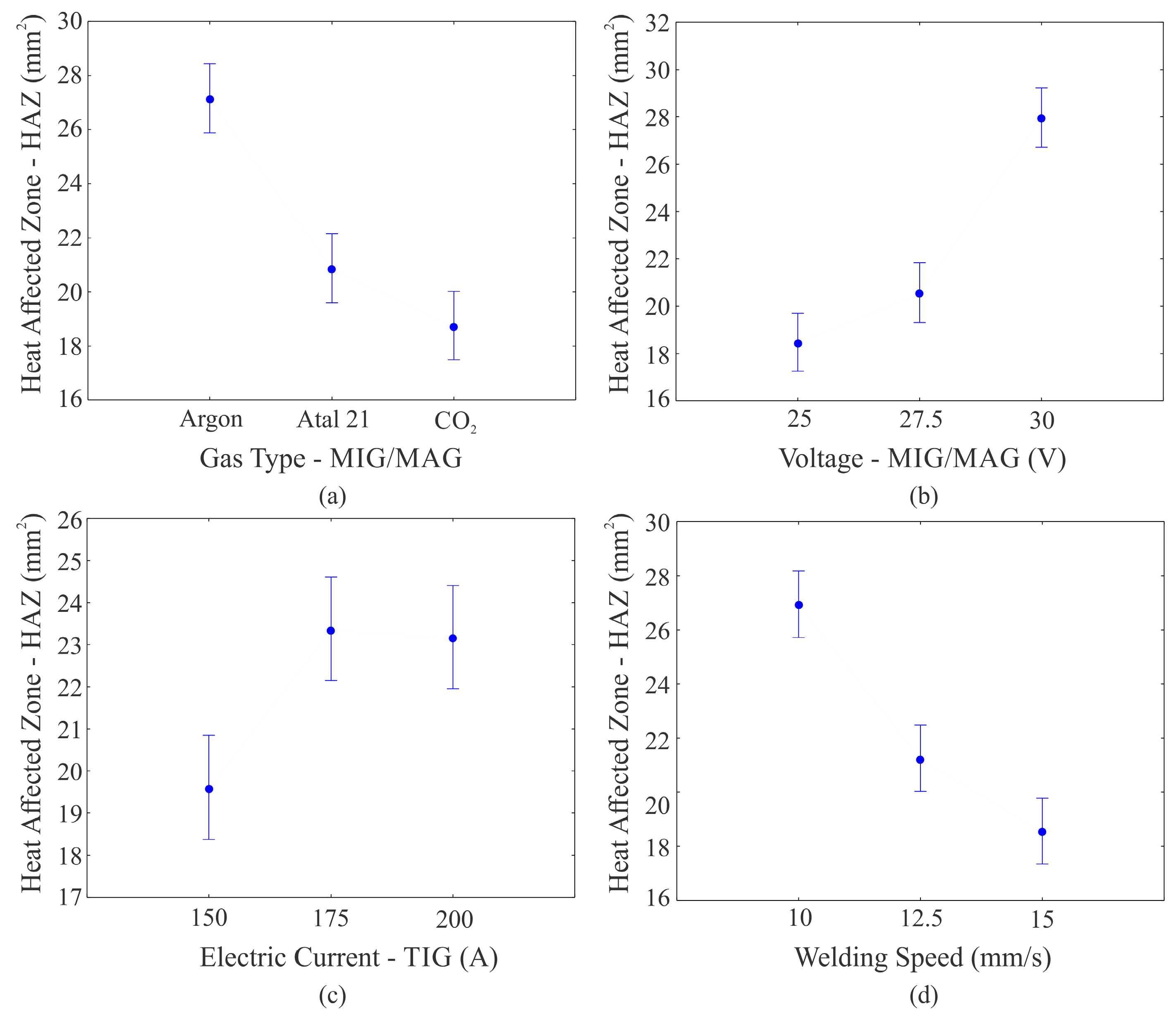
Figure 6a shows the HAZ area as a result of the type of shielding gas (MIG/MAG). Note that the smallest values tend to be obtained using CO
2 gas, while the greatest HAZ is obtained when argon gas is used. As to the influence of the MIG/MAG voltage on the HAZ, shown in
Figure 6b, it is seen that increasing the MIG/MAG voltage increases the area of the HAZ.
Figure 6c shows the graph of the area of the HAZ as a result of the intensity of the electric current (TIG), where it is visible that the lowest values of the HAZ should be reached with the minimum level of electrical current, and the highest averages of the HAZ were obtained with the highest electric current levels.
Figure 6d plots the welding speed based on the area of the HAZ, in which it is observed that on increasing the welding speed, the area of the HAZ decreases.
The variations presented follow the tendency for the HAZ area. Thus, inert gases, such as argon, give the process higher heat rates, thereby increasing the area of the HAZ. Likewise, an increase in the voltage (MIG/MAG), an increase in the electric current (TIG) and a decrease in the welding speed tend to cause the HAZ to increase. The extent of the HAZ depends primarily on the base material, the weld filler metal and the amount and concentration of heat input by the welding process. As the base material and the filler metal are the same for all carry out welds, the thermal input is a physical quantity that changes a region of the HAZ, i.e., when the voltage (MIG/MAG) and electric currents (TIG and MIG/MAG) increase, the HAZ region increases, and when the welding speed increases, the HAZ region decreases, because the thermal input is directly proportional to electric current and voltage and inversely proportional to welding speed.
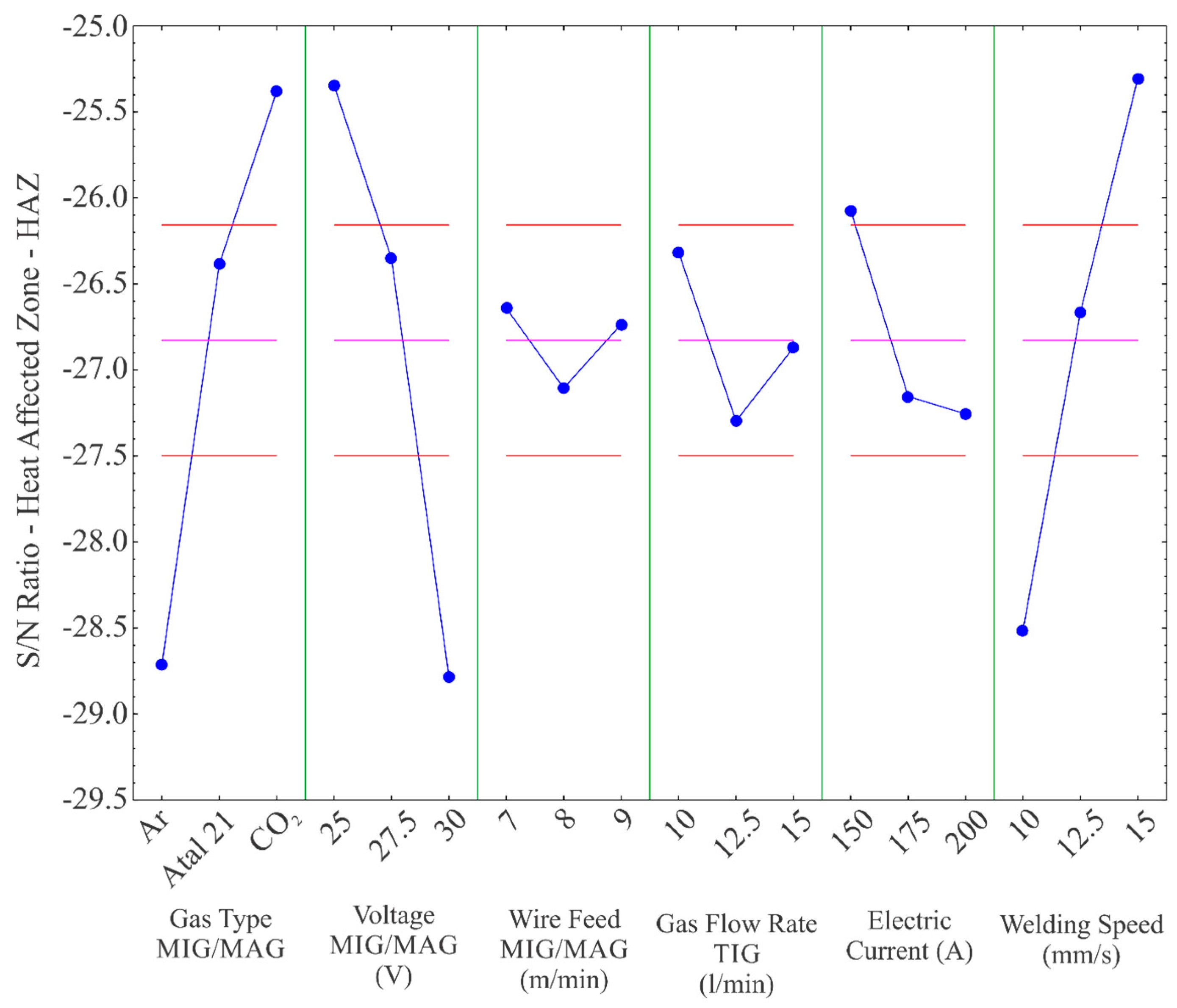
To optimize the HAZ area, the option smaller is better was selected, thus demonstrating that what is desired is to obtain the smallest possible HAZ area with the factors tested.
Figure 7 plots the S/N ratio for the HAZ area, where the values of the factors that presented the highest S/N ratio are those indicated for optimizing the process. The smallest HAZ area should be obtained by using CO
2 as the shielding gas (MIG/MAG), voltage of 25 V (MIG/MAG), wire feed speed (MIG/MAG) equal to 7 m/min, flow of the shielding gas (TIG) of 10 L/min, intensity of electric current (TIG) of 150 A and welding speed of 15 mm/s.
A test specimen was constructed with the values defined by the signal-to-noise ratio (S/N) so as to obtain the smallest HAZ area. The value found was an HAZ area of 9.33 mm
2, as per
Figure 8, which confirms optimization, since this was the lowest value found in the experiments. Through these values, the smallest HAZ region was obtained because less thermal input was generated.
3.3. Bead Width
The most important factors influencing the width of the weld bead were the type of MIG/MAG shielding gas, the MIG/MAG voltage, the welding speed, the flow rate of the TIG shielding gas and the electric current (TIG), respectively. This can be seen in the variance analysis presented in
Table 5, which indicates, for these factors, a value of
p less than 0.05 and a value of
f that indicates the order of the influence of the factors on the width. The feed velocity of the wire (MIG/MAG) obtained a
p-value greater than 0.05 in the variance analysis. Therefore, the effects of this parameter on the width cannot be reliably stated.
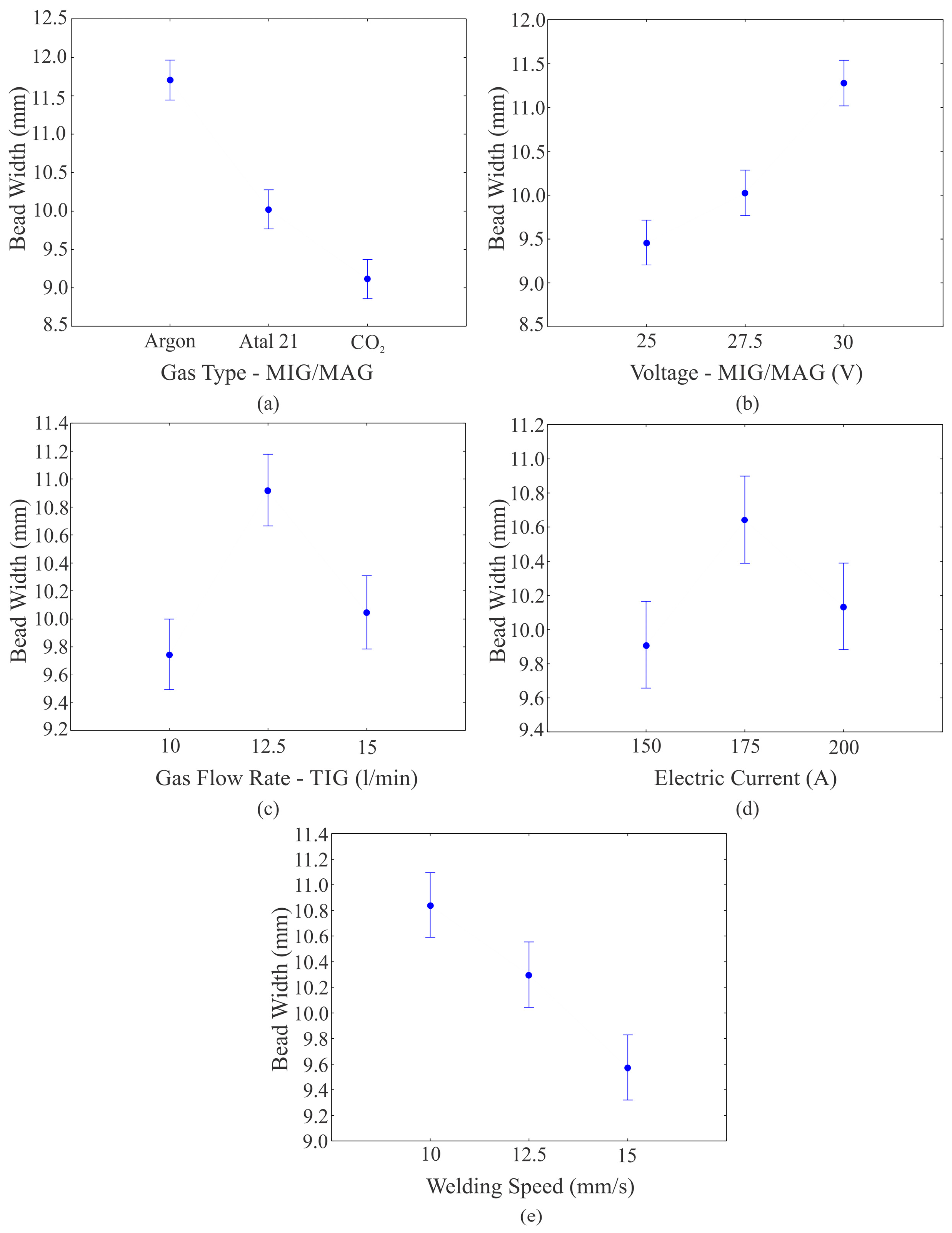
Figure 9a shows the graph of the average width of the weld bead based on the type of shielding gas (MIG/MAG), in which it can be observed that by increasing the amount of CO
2 the width of the weld bead decreases. Its width tends to increase when the MIG/MAG voltage is increased. This can be seen in
Figure 9b, which shows the graph of the average width of the weld bead based on the voltage (MIG/MAG).
Figure 9c shows the average width of the weld bead based on the flow of the TIG shielding gas, in which the largest width was reached by using an intermediate flow level (12.5 L/min), while the smallest weld bead widths were obtained when the flow was used at its minimum and maximum level. The graph of the average width of the weld bead based on the intensity of the electric current (TIG), plotted in
Figure 9d, shows that the intermediate level of electric current tends to obtain the largest weld bead widths.
Figure 9e shows the average width of the weld bead based on the welding speed. The graph shows that the increase in speed resulted in a decrease in the width of the weld bead.
The influences of the MIG/MAG voltage and the welding speed on the width follow that specified in the literature [
26], which indicates that an increase in width takes place when the MIG/MAG voltage is increased and/or the welding speed is reduced. The concept of the conventional TIG welding process for the welding current did not apply to this process. In fact, the highest electric current (TIG) did not cause the greatest widths. However, this is not a conventional process, and this parameter may have been influenced by other factors of the hybrid welding process. In the TIG-MAG in tandem welding process developed by [
15], the TIG factors did not even show significant influence on the width. The only significant factors for this response were the MAG/MIG voltage and the welding speed. The bead width increases with increasing voltage due to increase of the electric arc width over the melt pool. Furthermore, the bead width may increase due to the hybrid arc having a greater area of contact with the piece; consequently, the greater the heated area, the greater the wettability and the greater the bead width.
The graph of the S/N ratio for the largest width is shown in
Figure 10. According to the graph, what is defined is that the largest weld width is obtained with the shielding gas (MIG/MAG) argon, voltage (MIG/MAG) of 30 V, wire-feed speed (MIG/MAG) of 9 m/min, gas flow (TIG) of 12.5 L/min, electric current intensity (TIG) of 175 A and welding speed of 10 mm/s.
A new sample was welded with the factors indicated, for which the width obtained was 11.61 mm, as per
Figure 11.
The specimen welded for this optimization did not obtain the greatest width when compared to the twenty-seven samples. However, the samples that reached widths greater than those of the optimized sample obtained high levels of undercut (what was considered as width, consequently increasing the measurements). Thus, by analyzing the welds without this defect, it can be affirmed that the optimization was effected for this variable.
3.4. Bead Height
In the analyses performed to reinforce the weld, an optimization was carried out in order to minimize it, yet, with the condition that it existed in the weld, that is it had a value greater than zero.
In the analysis of variance, the values of
p lower than 0.05 were the wire-feed speed (MIG/ MAG) and the intensity of the electric current (TIG). Thus, it is stated with a confidence of over 95% that these factors influenced bead height. As for the other factors, nothing can be said. The variance analysis for the bead height of the weld can be seen in
Table 6.
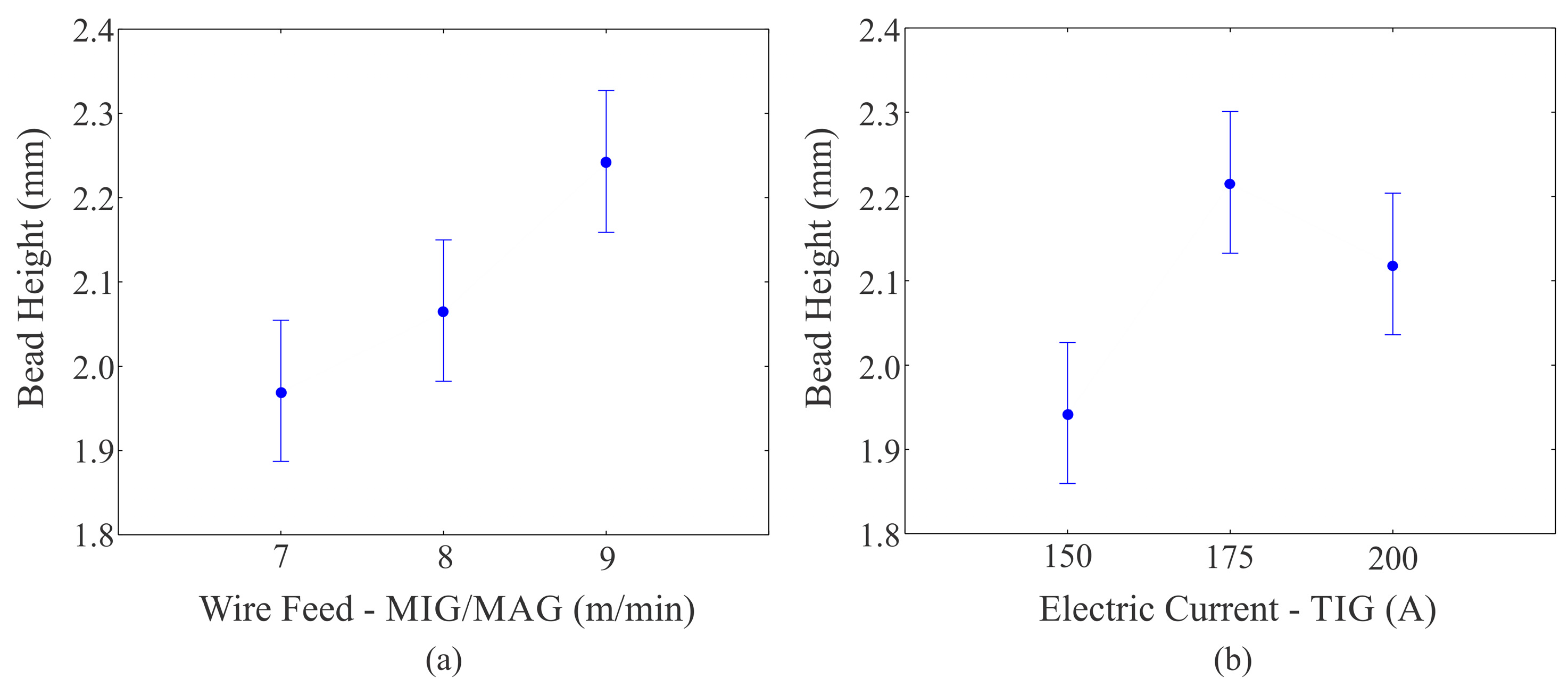
The tendency of bead height behavior in relation to the factors that had a significant influence can be seen in
Figure 12. The parameter that showed the greatest influence on bead height was the feed velocity of the wire (MIG/MAG). The trend shown in
Figure 12a indicates that the bead height increased when the wire-feed speed (MIG/MAG) increased.
Figure 12b shows the graph of the bead height based on the intensity of the electric current (TIG). The tendency was that the greatest bead heights are reached with the intermediate level and the smallest bead heights with the minimum level of current. Furthermore, in this hybrid process, the bead height is reduced due to the preheating generated by the TIG process.
The bead height consists of the height of material deposited above the surface of the weld. Thus, the tendency is that an increase in the speed of the wire (material deposition) causes an increase in the bead height.
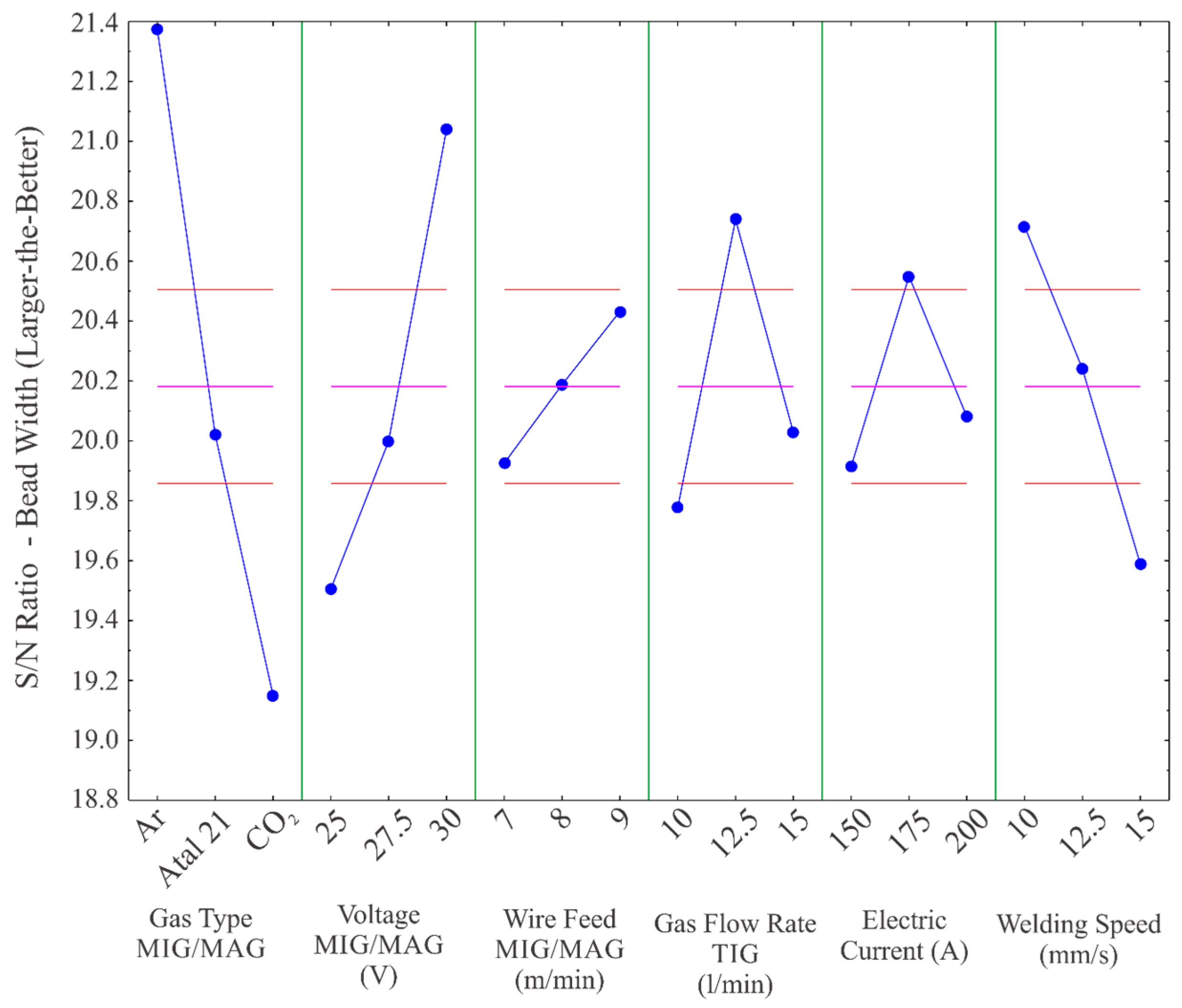
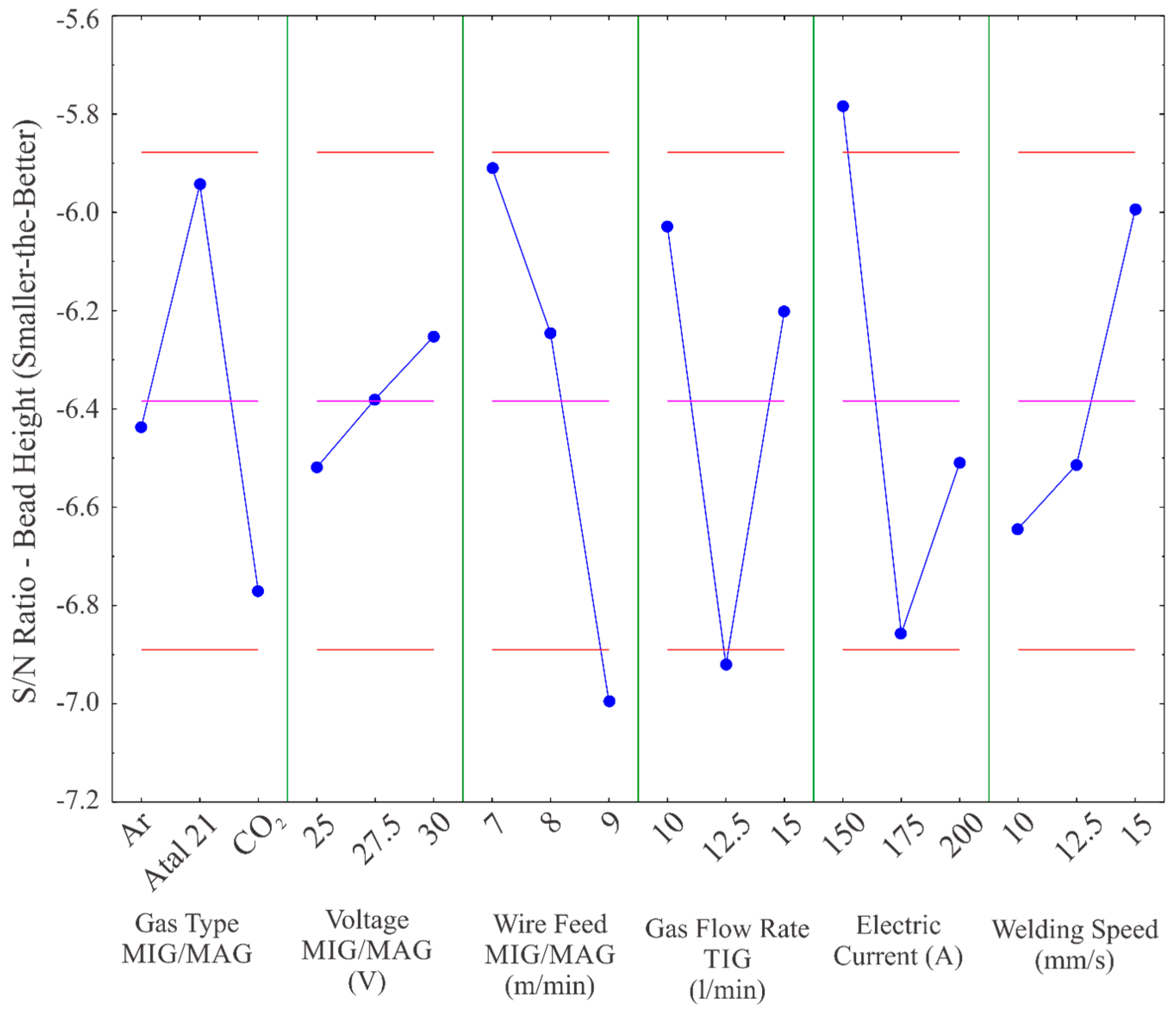
The graph of the S/N ratio, shown in
Figure 13, shows the factors indicated for optimizing the bead height in relation to the condition smaller is better, namely it presents the factors used to obtain the smallest bead height. The values indicated consist of the shielding gas (MIG/MAG) Atal 21, 30 V of voltage (MIG/MAG), wire feed speed (MIG/MAG) of 7 m/min, shielding gas flow (TIG) of 10 L/min, electric current intensity (TIG) of 150 A and a welding speed of 15 mm/s.
The test specimen was welded to confirm the values indicated by the S/N ratio. This showed a bead height of 1.47 mm. The confirmation sample is shown in
Figure 14.
The optimized test specimen achieved the lowest bead height, compared to the bead heights of the other experiments. This proves the optimization performed for this variable.
4. Conclusions
In this work, an experimental study was carried out on a hybrid welding technology consisting of the TIG and MIG/MAG welding processes, in an automated way on SAE 1045 steel workpieces.
The optimization of the hybrid welding process was carried out in relation to the weld bead geometry (penetration, HAZ, weld bead width and bead height). Using the S/N ratio, the process was optimized for each of the output variables studied, and the optimization was confirmed by welding new test specimens.
By conducting a variance analysis, the influences of the welding factors on the four output variables were detected. The factors that had significant influences on penetration were the type of shielding gas (MIG/MAG), the voltage (MIG/MAG), the wire feed speed (MIG/MAG) and the welding speed. The HAZ was significantly influenced by the type of shielding gas (MIG/MAG), voltage (MIG/MAG), intensity of the electric current (TIG) and welding speed. The factors that had effects on the width of the weld bead were the type of shielding gas (MIG/MAG), the voltage (MIG/MAG), the flow of shielding gas (TIG), the intensity of the electric current (TIG) and the speed of welding. Bead height was significantly influenced by the feed velocity of the wire (MIG/MAG) and by the intensity of the electric current (TIG).
Finally, other studies should be carried out in order to understand the influence of other factors (angles, distances between electrode and wire, etc.) on the geometry of the weld bead. Furthermore, a study of the thermal efficiency of this process could be developed.

 and
and 


