Evaluating the Directional Stability of Alpine Skis through the Simulation of Ski Deformation during a Steady-State Turn †


Department of Mechanical Engineering, University of Sherbrooke, Sherbrooke, QC J1K 2R1, Canada
*
Author to whom correspondence should be addressed.
†
Presented at the 12th Conference of the International Sports Engineering Association, Brisbane, Queensland, Australia, 26–29 March 2018.
Proceedings 2018, 2(6), 315; https://doi.org/10.3390/proceedings2060315
Published: 22 February 2018
(This article belongs to the Proceedings of The 12th Conference of the International Sports Engineering Association)
Abstract
:Directional stability is an important performance criterion for alpine skis and has been shown to correlate with the second moment of running surface pressure distribution. However, this stability index is complex to measure while skiing and is not practical for testing many skis. It therefore remains unclear what range one can expect in the variation of stability between commercially available skis. In this study, the mechanical properties of 179 skis were measured and the ski deformation was simulated during a steady-state turn to evaluate the stability index. The resulting data provide insight as to what values of stability, which ranged from 0.1 to 98 N m², are to be expected. A novel parameter, the product of the force required to flatten a ski and the square of its sidecut length, was introduced. Its high correlation with a ski’s stability suggests it can be used as an accurate predictor of stability.
1. Introduction
It is widely accepted that directional stability is a decisive criterion in determining the performance of an alpine ski during a carved or skidded turn [1,2,3,4]. This stability is correlated with the way the pressure is longitudinally distributed along the base of the ski at the ski/snow interface [1,3]. One proposed quantitative performance index to evaluate stability is the second-order moment of pressure distribution along the longitudinal axis of the ski [3]. However, this performance index is difficult to measure in actual use, requiring specialized and bulky equipment [5]. Further complicating matters, on hard snow or ice, the pressure distribution is limited to a very thin area along the edge of the ski. At least one study has been conducted to experimentally measure the pressure distribution and stability index of skis in a laboratory setting, on a rigid surface [3]. Another method of obtaining the stability index of a ski is to numerically simulate the ski deformation and resulting snow penetration and interface pressure during a turn. There is a large body of work concerning modelling a ski turn on snow using either static [6,7] or dynamic models [8,9]. The ski has been modelled using various methods: an elastic beam [6], a set of elastically-connected rigid bodies [7,8,9,10], or using FEM [11]. The snow has also been modelled in various ways, either using an extrapolation of ice-cutting experiments [12], as a linear elastic material [8] or using a plastic/hypoplastic law [6,7,9,10,13]. However, simulations require accurate mechanical properties which have historically been difficult to obtain, specifically in the case of the bending and torsional stiffness profiles. This explains in part the limited number of different skis analyzed in the above studies. Recently, a method was developed to quickly and accurately measure these stiffnesses [14].
The aim of this study was to determine the range of stability that can be expected from typical, commercially available skis by analyzing, using numerical simulation, a large number of skis spanning various disciplines and sizes. A secondary aim of this study was to understand how the relevant mechanical properties (ski length, sidecut, camber, as well as bending and torsional stiffness distributions) affect this stability. This knowledge would be invaluable to ski designers, enabling them to use the stability index as a design goal, selecting an appropriate stability target and sizing the ski’s properties to attain this goal. For consumers, knowledge of the preferred stability level for one’s own abilities and style would facilitate the ski selection process by quickly eliminating skis exhibiting inappropriate stability values.
To fulfill these objectives, the mechanical properties of 179 different skis were measured using the SMAD method [14]. Section 2 describes the numerical model used to simulate the ski deformation and pressure distribution. In Section 3, the results obtained from this model for the measured skis are analyzed. The effect of linear and hypoplastic snow deformation laws on stability are compared. The effect of a ski’s mechanical properties on stability are also investigated and a simple parameter encompassing a ski’s various mechanical properties is proposed to quickly estimate stability.
2. Materials and Methods
2.1. Selected Skis
In this study, the sidecut, camber and bending and torsional stiffness profiles were measured for 179 different skis using the SMAD method. Using this method, the stiffness profiles were obtained with an accuracy of approximately 5% [14]. The skis measured were all commercially available models spanning a range of intended uses, and measuring from 146 to 189 cm in nominal length. The width of the skis varied from 64 to 122 mm. The mean bending and torsional stiffness values varied from 113 N m² to 369 N m² and 48 to 350 N m², respectively.
2.2. Ski Model
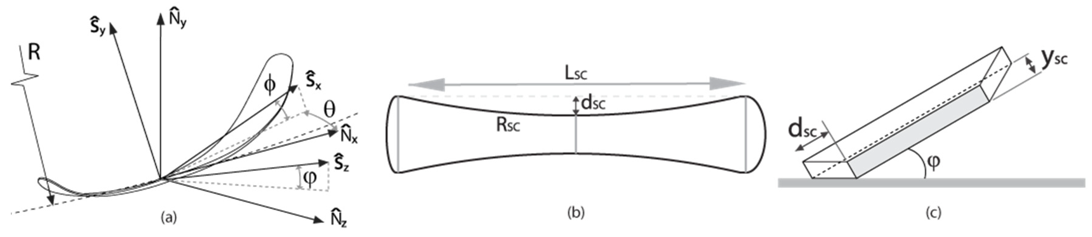
Two reference frames are used throughout this study: , the normal-tangential reference frame with respect to the ski trajectory (assumed to be circular and of radius ), as well as , a reference frame aligned with the ski. Starting from , can be obtained from 3 successive rotations. Firstly, the ski, initially resting on the snow surface, is rotated around by an angle , which is the angle of attack of the ski with respect to its trajectory. Then, the ski is rotated around by an angle , which represents lateral lean. Finally, the ski is rotated around by an angle , which represents fore/aft lean. Figure 1a illustrates the orientation of these references frames for a typical ski turn.
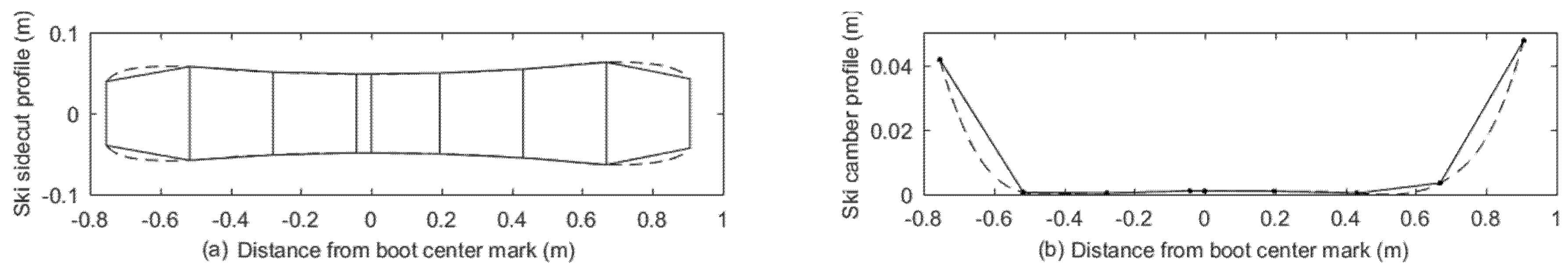
A single ski is modelled using a set of 31 elastically-connected rigid-body trapezoids. The positions of the trapezoidal segments’ vertices are chosen to coincide with the sidecut and camber profiles of the undeformed ski. Figure 2 shows a 7-segment ski (for visual clarity) overlaid onto the continuous geometry profiles.
The segments are rigidly connected in translation at nodes located on the center of the common edges of the undeformed shape. The lateral bending degree of freedom is blocked, and the bending and torsion degrees of freedom are linked by springs whose stiffnesses are calculated from the continuous stiffness profiles, and , and the segment length, as given by Equation (1) [15]:
2.3. Snow Models
The snow reaction force on each ski segment is calculated using either a linear elastic or hypoplastic constitutive law. In both cases, the force is assumed to be normal to the ski segment. Tangential forces such as friction are neglected. Shear resistance of the snow is considered to be infinite. In the case of the linear elastic model, the snow force component along acting on the segment j is given by Equation (2), where is the snow surface stiffness. For the hypoplastic model, this force is rather given by Equation (3) with and [9,13]. The force is calculated by numerically integrating the penetration over the whole segment, with the maximum snow penetration, , carrying over from the front-most segments rearwards. Since the total snow force is perpendicular to the ski segment surface, it is calculated with knowledge of , the angle between the segment surface normal vector and (Equation (4)). The force is applied at the segment’s center of pressure.
2.4. Solver
A prescribed, constant force is applied perpendicularly to the snow surface () at a node positioned on the central segment at the ski center to represent the skier’s weight. The central segment’s orientation () as well as the trajectory radius , as defined in Figure 1a, are also fixed. As such, any dynamic effects (weighting/unweighting, convexities/concavities on the snow surface and weight transfer between the two skis) are not considered by this steady-state model.
The snow forces acting on each individual ski segment, as well as the node and force positions, and , are used to calculate the nodal moments in the reference frame, which are then transferred to the segment reference frames () with the rotation matrix , as in Equation (5).
Thus, the net moment at each node is the sum of the node internal spring moment and the moment due to snow forces, as given by Equation (6). Similarly, the total force normal to the snow surface is the sum of the snow forces and the applied force at the ski center and is given by Equation (7). An iterative solver is used to find the steady-state ski deformation, which is the solution to equation set 8.
The solver code was validated by replacing the snow model with boundary conditions emulating a 3-point bending test and finding the solution for a constant-stiffness beam. The solution was identical to within 3% of the deformation predicted by Euler-Bernoulli beam theory.
2.5. Pressure Distribution and Stability Index
The stability index, corresponding to the second-order moment of pressure distribution along the longitudinal axis of the ski, , is calculated with Equation (9). In contrast with previous work [3], the non-normalized moment is used to compare the absolute stability values.
3. Results and Discussion
The turn simulations were carried out for boot orientations ranging from 1 to 45° of lateral lean and from −10 to 10° of fore/aft lean. Applied normal forces ranged from 196 to 589 N (20 to 60 kg) and snow hardness was varied from 1 × 10⁶ to 1 × 10⁹ N/m³. For the hypoplastic snow model, angle of attack and trajectory radius were also considered to construct the snow deformation path. These parameters were varied from 0 to 5° and 10 to 50 m, respectively.
3.1. Effect of Torsional Stiffness
A subset of five skis within the set of studied skis, selected to cover the whole range of torsional stiffnesses of the complete set, were modelled with both the model described above and with the torsional degree of freedoms blocked. The average difference in the stability index for all the simulations was 2.1%, with a standard deviation of 2.9%, which suggests that torsional stiffness has a negligible effect on stability. Torsional stiffness was thus neglected from subsequent analyses.
3.2. Comparison between Linear and Hypoplastic Snow Models
Because of computational time constraints, two skis were simulated using the hypoplastic snow model. Across the whole range of input parameters, the difference between the stability index predicted using the hypoplastic and the linear snow model did not exceed 16%. Also, the error decreased to under 10% for angles of attack above 2.5°, which is coherent with previous work: at small angles of attack, the hypoplastic model predicts that ski tail rides through the groove created by the ski shovel, reducing tail pressure [7] and, in turn, the stability index. At larger angles of attack, the ski tail does not track the groove created by the shovel, and the pressure distribution more closely resembles that predicted by the linear model. Although previous work [9] has shown that a hypoplastic law models snow behavior more accurately than a linear elastic law, this difference in stability predicted by the two snow models is small relative to the difference between skis. The linear model is therefore used for further analyses to reduce both computing time and the number of inputs: for the linear model, angle of attack and trajectory radius are trivial and need not be considered.
3.3. Fore/aft Lean Angle Effect on Stability
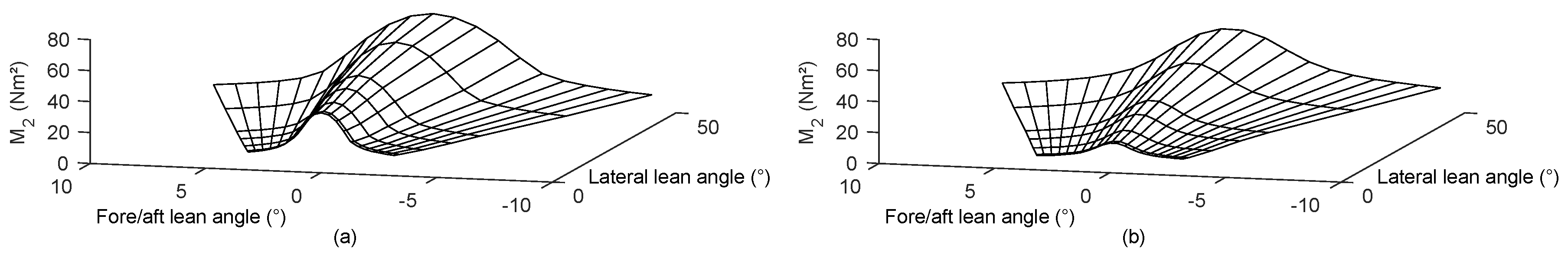
For all the skis considered in this study, maximum stability for a given snow hardness, applied force and lateral lean angle occurs at or very near zero fore/aft lean angle, i.e., leaning forwards or backwards has the effect of decreasing stability. This is visible in Figure 3, which shows two typical maps of stability as a function of fore/aft and lateral lean angles for both a traditionally cambered ski and for a rockered ski. Although the amplitudes and slope of the map vary for different skis, snow hardnesses and applied forces, all stability maps retain a similar shape.
3.4. Comparison of Stability across Different Skis
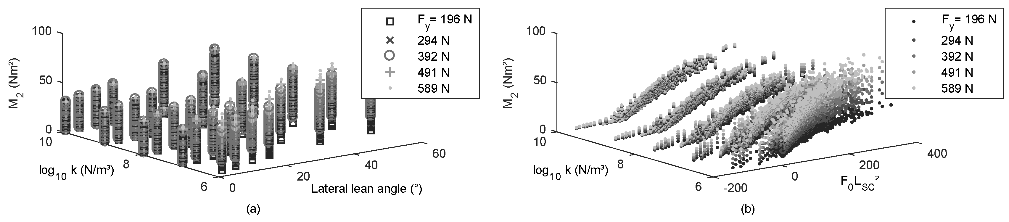
The stability index calculated for the 179 skis studied, in all conditions considered, varied from 0.1 (for rockered skis) up to 98 N m². Since maximum stability is achieved at or near zero fore/aft lean angle, other angles were not considered. As can be seen in Figure 4a, decreasing snow hardness has the effect of increasing stability while increasing lateral lean angle and applied loads both increase stability. However, even for a single hardness, applied load and lateral lean angle, the stability from ski to ski varies significantly. This is because the mechanical ski properties also influence stability.
3.5. Stability as a Function of the Force Required to Flatten The Ski
To gain insight on the effect of a ski’s mechanical properties on the stability index, we think of the ski as a simplified, constant-stiffness beam in simply supported, center-loaded bending. , the force required to deform such a beam a distance , is given by Equation (10).
In Equation (10), the sidecut length, , is defined as the distance between the widest point of the shovel and the widest point of the tail (Figure 1b), and is the ski’s mean bending stiffness. If the ski is pressed onto a rigid surface, the distance y will then be equal to the sum of the ski’s initial camber and the additional distance through which the ski must be flexed due to its’ sidecut when it is on edge, (Figure 1c). This additional deflection can be calculated from the ski’s sidecut length and radius, and , and the lateral lean angle, as given by Equation (11) [1]. For rockered skis, the camber is negative and is calculated as the vertical distance between the boot center mark and a line traced between the widest points of the shovel and the tail.
From this simple ski model, we then introduce the parameter (since stability varies with the square of the length), as given by Equation (12). Figure 4b shows the stability index as a function of this simplified parameter, snow hardness and applied force, for all skis at all lateral lean angles.
A model was fitted to this data to evaluate the goodness of the fit when using as a predictor of stability. Negative values of were considered to be equal to zero for the data fitting, since a ski cannot be flexed downwards by the snow surface. Equation (13) presents the fitted model ().
The high coefficient of determination suggests that is adequate to quickly estimate the stability of a ski. Furthermore, it is the only fit parameter that depends on the ski’s properties, which indicates it is, by itself, sufficient to compare stability between skis. Deviation from the fit can easily be explained by the fact that this simplified parameter makes use of many simplifications: we assume that the maximum camber, the sidecut and the applied load are all centered on the ski and that the ski is a constant beam with stiffness equal to the mean bending stiffness. The actual camber and sidecut profiles, the stiffness distribution and the boot center mark location will all influence the stability index. These effects are taken into account by the steady-state turn model but not by .
The correlation between stability and is of importance since calculating this simple parameter does not require numerical simulation or on-snow tests; it is sufficient to have a ski’s design data or to measure it using a relatively simple machine [14]. It could therefore easily be calculated for all existing skis, enabling one to directly compare skis on the basis of a performance parameter instead of relying on the underlying mechanical properties. Amongst the 179 skis studied, varied from −144 to 112 Nm² at zero lateral lean angle and from −21 to 324 N m² at 45°. Also, the fitted model in equation 13 makes it possible for a designer or consumer to quickly estimate a ski’s stability index for a given set of turn conditions (lean angle, snow hardness, force applied on the ski).
4. Conclusions
The aim of this study was to determine the range of stability of commercially available alpine skis, as determined by the second-order moment of the pressure distribution along the longitudinal axis of the ski. A secondary aim of this study was to gain insight on the effect of a ski’s mechanical properties on stability. The sidecut, camber and bending and torsional stiffness profiles of 179 skis were measured. These were fed into a steady-state turn model for various snow hardnesses, applied forces, and ski orientations. The results show that the stability index varies from almost 0 (for some rockered skis) to 98 N m² for snow hardnesses of 1 × 10⁶ to 1 × 10⁹ N/m³, applied normal forces of 196 to 589 N and lateral lean angles of 1 to 45°. A simplified parameter, , was introduced and was shown to be an accurate predictor of stability. Since this parameter depends only on a ski’s mechanical properties and is independent of snow and turn conditions, it can easily be calculated and made available for consumers to compare models and select an appropriate ski based on the desired level of stability. It could also allow designers to size a ski’s mechanical properties to obtain a stability level coherent with the ski’s intended use.
Supplementary Materials
The list of skis used in this work is available online at www.mdpi.com/2504-3900/2/6/315.
Acknowledgments
This research was supported in part by grants from the Natural Sciences and Engineering Research Council of Canada (NSERC) and the Fonds de Recherche Nature et Technologies du Québec (FRQNT).
Conflicts of Interest
The authors declare no conflict of interest. The funding sponsors had no role in the design of the study; in the collection, analyses, or interpretation of data; in the writing of the manuscript, and in the decision to publish the results.
References
- Howe, J.G. Skiing Mechanics; Poudre Press: Vienna, Austria, 1983. [Google Scholar]
- Federolf, P.; Auer, M.; Fauve, M.; Lüthi, A.; Rhyner, H. Subjective evaluation of the performance of alpine skis and correlations with mechanical ski properties. In The Engineering of Sport 6; Springer: Berlin/Heidelberg, Germany, 2006; pp. 287–292. [Google Scholar]
- De Cecco, M.; Angrilli, F. Testing ski stability. Meas. Sci. Technol. 1999, 10, N38. [Google Scholar] [CrossRef]
- Subic, A.; Clifton, P.; Beneyto-Ferre, J.; LeFlohic, A.; Sato, Y.; Pichon, V. Analysis of Snowboard Stiffness and Camber Properties for Different Riding Styles. In The Engineering of Sport 7; Springer: Berlin/Heidelberg, Germany, 2008; pp. 319–327. [Google Scholar]
- Scott, N.; Yoneyama, T.; Kagawa, H.; Osada, K. Measurement of ski snow-pressure profiles. Sports Eng. 2007, 10, 145–156. [Google Scholar] [CrossRef]
- Kaps, P.; Mössner, M.; Nachbauer, W.; Stenberg, R. Pressure Distribution under a Ski During Carved Turns. In Proceedings of the Science and Skiing, Hamburg, Germany, 9–15 January 2001. [Google Scholar]
- Heinrich, D.; Mössner, M.; Kaps, P.; Nachbauer, W. Calculation of the contact pressure between ski and snow during a carved turn in Alpine skiing. Scand. J. Med. Sci. Sports 2010, 20, 485–492. [Google Scholar] [CrossRef] [PubMed]
- Nordt, A.A.; Springer, G.S.; Kollár, L.P. Simulation of a turn on alpine skis. Sports Eng. 1999, 2, 181–199. [Google Scholar] [CrossRef]
- Mössner, M.; Heinrich, D.; Schindelwig, K.; Kaps, P.; Schretter, H.; Nachbauer, W. Modeling the ski-snow contact in skiing turns using a hypoplastic vs an elastic force-penetration relation. Scand. J. Med. Sci. Sports 2014, 24, 577–585. [Google Scholar] [CrossRef] [PubMed]
- Bruck, F.; Lugner, P.; Schretter, H. A Dynamic Model for the Performance of Carving Skis; ASTM Special Technical Publication; ASTM: West Conshohocken, PA, USA, 2003; Volume 1440, pp. 10–23. [Google Scholar]
- Federolf, P.; Roos, M.; Lüthi, A.; Dual, J. Finite element simulation of the ski-snow interaction of an alpine ski in a carved turn. Sports Eng. 2010, 12, 123–133. [Google Scholar] [CrossRef]
- Lieu, D.K. Mechanics of the Turning Snow-Ski; University of California: Berkeley, CA, USA, 1982. [Google Scholar]
- Mössner, M.; Heinrich, D.; Schindelwig, K.; Kaps, P.; Lugner, P.; Schmiedmayer, H.-B.; Schretter, H.; Nachbauer, W. Modeling of the Ski-Snow Contact for a Carved Turn. In The Engineering of Sport 6; Springer: Berlin/Heidelberg, Germany, 2006. [Google Scholar]
- Truong, J.; Brousseau, C.; Desbiens, A.L. A Method for Measuring the Bending and Torsional Stiffness Distributions of Alpine Skis. Procedia Eng. 2016, 147, 394–400. [Google Scholar] [CrossRef]
- Mitiguy, P.; Banerjee, A.K. Determination of Spring Constants for Modelling Flexible Beams. Work. Model Tech. Paper 2000. [Google Scholar]
Figure 1.
(a) Bent ski during a turn with reference frames; (b) Ski sidecut length, radius and depth; (c) Ski bending deformation due to sidecut () when on edge.
Figure 1.
(a) Bent ski during a turn with reference frames; (b) Ski sidecut length, radius and depth; (c) Ski bending deformation due to sidecut () when on edge.

Figure 2.
Segmentation of a ski overlaid on the measured (a) sidecut and (b) camber profiles.

Figure 3.
Stability maps for (a) a Rossignol Hero Elite E-ST Carbon 166 cm and (b) a Völkl Mantra 177 cm. Both maps are for an applied force of 392 N and a snow hardness of 1 × 10⁶ N/m³.
Figure 3.
Stability maps for (a) a Rossignol Hero Elite E-ST Carbon 166 cm and (b) a Völkl Mantra 177 cm. Both maps are for an applied force of 392 N and a snow hardness of 1 × 10⁶ N/m³.

Figure 4.
(a) Stability versus snow hardness, lateral lean angle and applied load and (b) stability versus snow hardness, F0LSC² and applied load.
Figure 4.
(a) Stability versus snow hardness, lateral lean angle and applied load and (b) stability versus snow hardness, F0LSC² and applied load.

Publisher’s Note: MDPI stays neutral with regard to jurisdictional claims in published maps and institutional affiliations. |
© 2018 by the authors. Licensee MDPI, Basel, Switzerland. This article is an open access article distributed under the terms and conditions of the Creative Commons Attribution (CC BY) license (https://creativecommons.org/licenses/by/4.0/).
Share and Cite
MDPI and ACS Style
Truong, J.; Desbiens, A.L. Evaluating the Directional Stability of Alpine Skis through the Simulation of Ski Deformation during a Steady-State Turn. Proceedings 2018, 2, 315. https://doi.org/10.3390/proceedings2060315
AMA Style
Truong J, Desbiens AL. Evaluating the Directional Stability of Alpine Skis through the Simulation of Ski Deformation during a Steady-State Turn. Proceedings. 2018; 2(6):315. https://doi.org/10.3390/proceedings2060315
Chicago/Turabian StyleTruong, Jonas, and Alexis Lussier Desbiens. 2018. "Evaluating the Directional Stability of Alpine Skis through the Simulation of Ski Deformation during a Steady-State Turn" Proceedings 2, no. 6: 315. https://doi.org/10.3390/proceedings2060315