Towards a Combined CAD and CFD Development Process of a Wingsuit †

1
Institute of Textile Machinery and High Performance Material Technology (ITM), TU Dresden, 01062 Dresden, Germany
2
Institute of Fluid Mechanics (ISM), TU Dresden, 01062 Dresden, Germany
*
Author to whom correspondence should be addressed.
†
Presented at the 12th Conference of the International Sports Engineering Association, Brisbane, Queensland, Australia, 26–29 March 2018.
Proceedings 2018, 2(6), 228; https://doi.org/10.3390/proceedings2060228
Published: 22 February 2018
(This article belongs to the Proceedings of The 12th Conference of the International Sports Engineering Association)
Abstract
:A wingsuit gives the human body an airfoil-like shape to fly in the sky. The paper proposes a holistic design approach combining the fluid mechanical simulation of the function with appropriate CAE-software for the generation of pattern cuttings. A parametric CAD model of the flyer wearing a wingsuit is created enabling easy changes in its posture and the wingsuit geometry. The flow simulation is set up using a commercial CFD code. Since there is no database available for the flow around a wingsuit, validation is conducted for a delta wing. This configuration is close to a wingsuit in terms of geometry and flow regime, but simpler and with sound experimental data available. Boundary conditions, mesh and selected turbulence model are validated with this configuration and experience gained about parameters of the solution process. Due to the computational link between CAE and CFD it’s possible to accelerate the development of wingsuits.
1. Introduction
Mankind has always dreamt of flying like a bird. Wingsuit flying is a type of air sports that gives people the opportunity to fly with some glide angle. Inflated air chambers which are integrated into the wings or the suit itself create an airfoil shape and produce lift. Optimizing high performance sportswear traditionally requires lots of effort and personnel to achieve the desired functionality through the complex process of design and experimental investigations.
A CAE-based simulation has the potential to reduce production costs and speed up the process by reducing the time-consuming prototype procedure requiring direct contact with the athletes as well [1]. But the construction of such a model is a challenging task. The human body has a complex shape without exact definition [2]. As a remedy, scan data of a real human body are used in the first stage. By completing the surface data of the digital human body model, the desired posture can be generated and used for the development of the functional clothing.
A systematic aerodynamic development can be achieved using commercially available tools for computational fluid dynamics (CFD) in the planning and optimization phase of the elite sports apparel. Ski jumping is similar to wingsuit flying because changes in the athlete’s position and the space between the garments and the human body result in variable lift and drag in both cases [3,4,5]. For a ski jumper, the importance of factors influencing aerodynamics, such as the athlete’s capabilities and experience, the posture and the speed were studied for a wide range of angles of attack [6]. For other winter sports, like bobsleigh, the aerodynamic process optimization concerning the shape of the bobsleigh and the position of the drivers was assessed with satisfying outcome [7,8,9]. These investigations also focused on an effective digital development strategy. Additionally, improving the aerodynamic behavior of sports garments requires a profound understanding of material performance, textile construction and surface texture [2].
To simulate wingsuit flying, many influencing factors need to be taken into consideration. These include the body shape, posture and angle of attack as well as the geometry of the wingsuit in inflated condition. The flight aerodynamics depend mainly on the wingsuit shape and pilot’s experience [10]. Application of CFD software, however, requires extensive specialized knowledge.
Unfortunately, there are hardly any suitable data available for validating CFD of a wingsuit. This is remedied here by two complementary strategies. The first is to choose a delta wing for validating the principle CFD approach and developing guidelines for the simulation of the flow around the wingsuit. The shape of a delta wing is similar to a wingsuit flyer and has been considered repeatedly in the literature, so that reference data are available. Subsequently, the same rationale is followed for the 3D wingsuit flyer. In a second step wind tunnel data for lift and drag of a wingsuit were generated and used as gross validation for the final CFD simulations of the wingsuit.
2. Materials and Methods
2.1. Delta Wing Case Study and Lessons Learned
In the second international Vortex Flow Experiment VFE-2 a delta wing was constructed and investigated experimentally [11]. As the leading edge shape determines the form and the place of the vortex on the upper surface, both sharp leading edge (SLE) and medium rounded leading edge (MRLE) were investigated. Simulations with partial resolution of the turbulence were conducted in several later studies, such as [12].
In the present study investigations for the delta wing geometry were carried out for the angles of attack α = 13°, 18°, 23°, Mach numbers M = 0.07, M = 0.14, and Reynolds numbers, based on the mean aerodynamic chord, of Remac = 1 × 10⁶ and Remac = 2 × 10⁶, respectively. These conditions are very similar to the ones of wingsuit flyers with Re = 2.8 × 10⁶ and M ≈ 0.1. To resolve the boundary layer along the profile, the grid was refined near the wall using prism layers while the outer flow was discretized with tetrahedra. ANSYS CFX was employed using two-equation RANS models (k-ε, k-ω, SST) and the BSL-RSM model. Numerous simulations were conducted for different physical conditions, different grids and turbulence models. In the following, selected representative results are reported. The SST model proved to be the most suitable for this application.
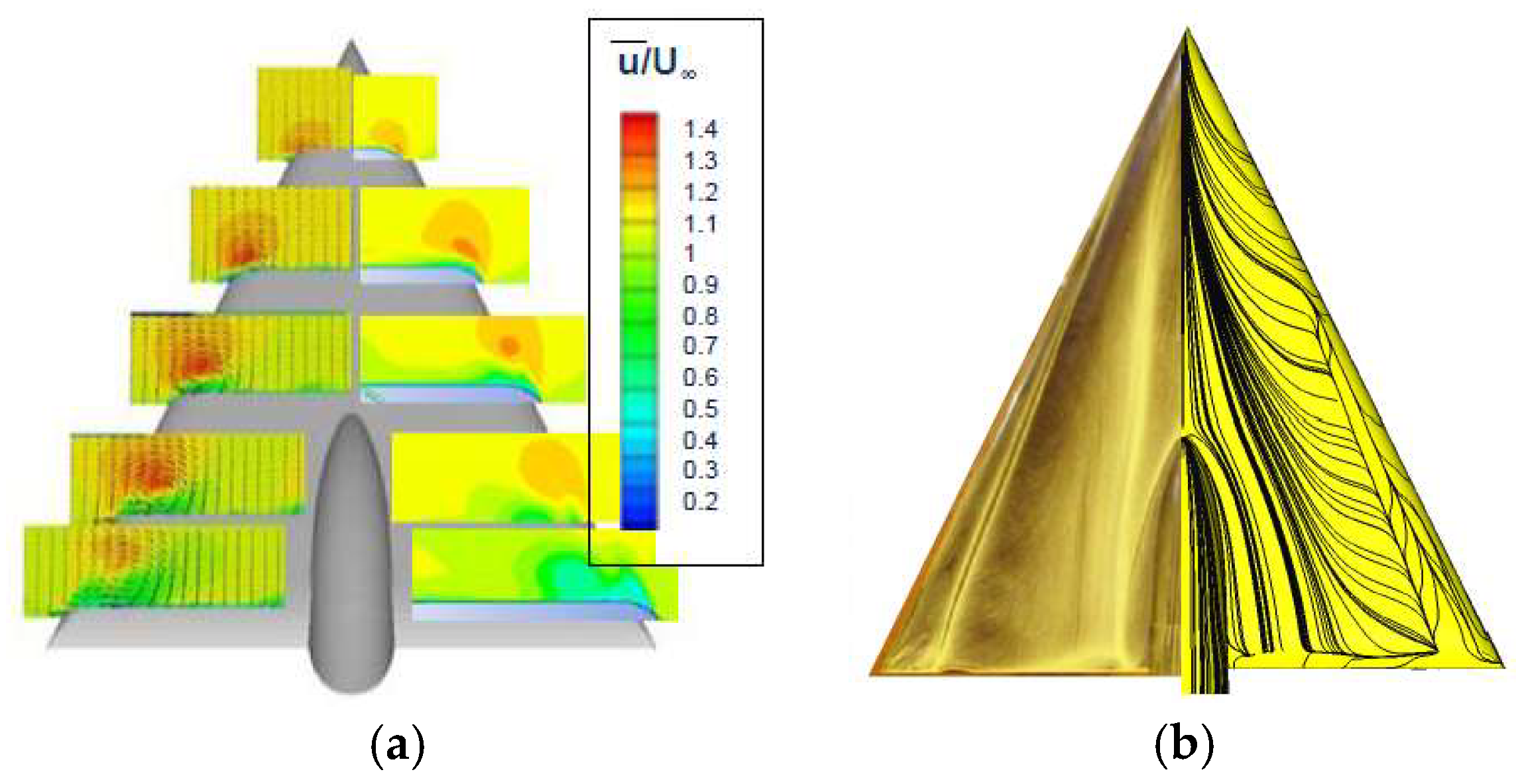
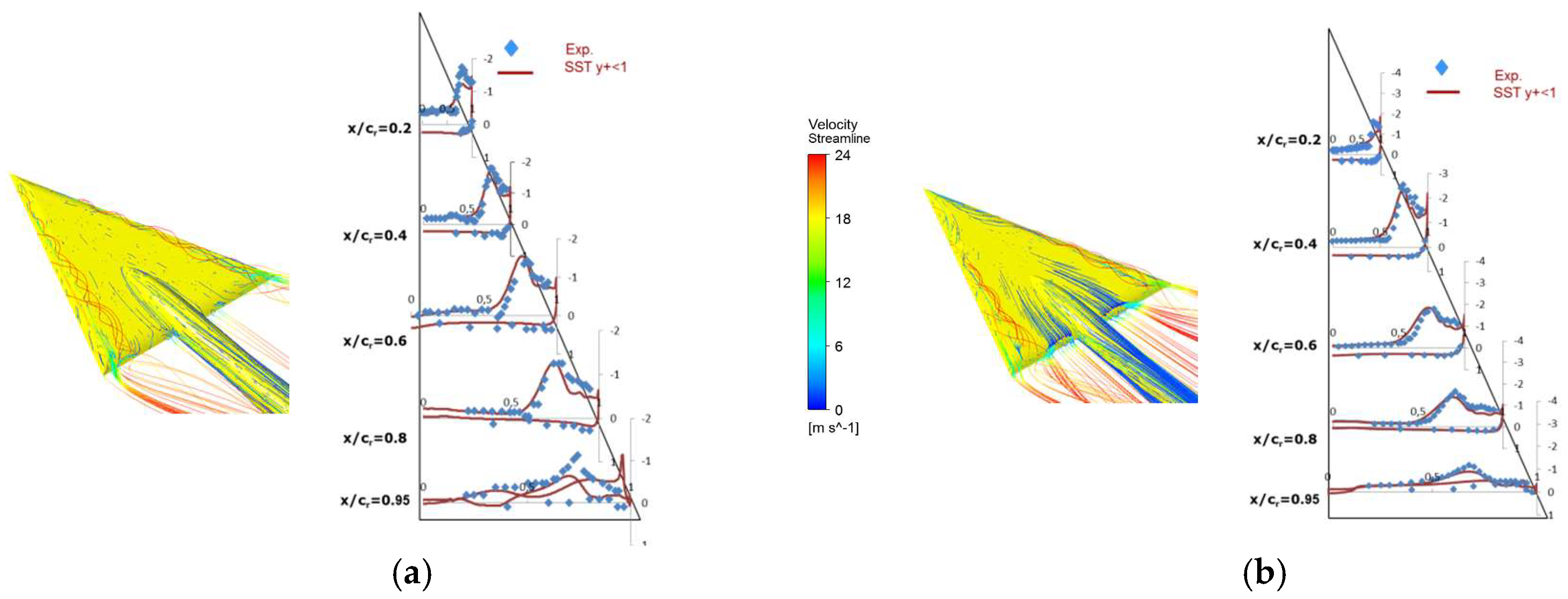
Vortex aerodynamics become significantly more complicated for rounded leading-edge configurations as the position of the primary separation varies to a certain extent depending on pressure gradient and boundary layer development. Figure 1 shows a comparison between experiment and simulation for the MRLE. In Figure 2, the time-averaged pressure coefficient Cp = (p-p∞)/q∞ is shown, where p is the static pressure, p∞ the free stream static pressure, and q∞ the free stream dynamic pressure [13]. The figure presents the pressure distribution at different chordwise stations for the sharp and the medium-rounded leading edge and an angle of attack of 13°. Figure 2 also shows Velocity streamlines highlighting vortex breakdown around the rear edges. All the other simulated flow characteristics for the delta wing were qualitatively and quantitatively predicted sufficiently well for the considered angles of attack and edge geometries.
2.2. Wingsuit
The wingsuit design and development process was carried out at ITM, TU Dresden in cooperation with the Rainbow Design company. Wind tunnel measurements were conducted at the Institute of Aerospace Engineering (ILR) at TU Dresden [14]. Important features of this wind tunnel are homogenous velocity due to its cross section (cross section diameter 2 m/3 m, length of the free measuring section 4.5 m, max. velocity 60 m/s) and low turbulence intensity (0.1%–0.5%). One- and two-piece wingsuits were examined and force measurements conducted using a multi-component balance.
The numerical model of the wingsuit was developed for three positions (normal, flat, high performance) illustrated in Figure 3. In the flat position, legs, body and head form a straight line. For the normal position, the legs are straight as well, but the upper body has a 13° upward bend. For the high performance position, the legs are bent downwards by about 13°, and the arms are also bent downwards increasing the cross sectional area. In the design process the flat position is considered the base geometry, and the other positions are derived from it.
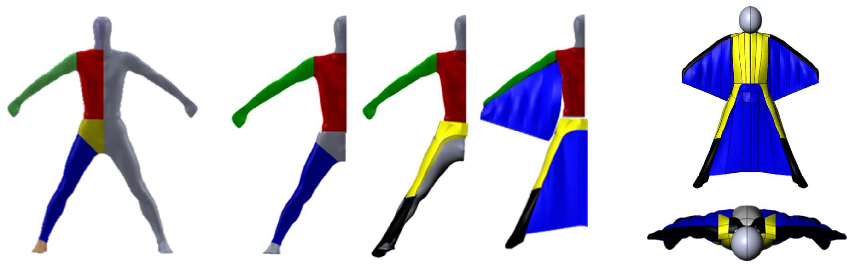
The digitalization of complex development processes has attracted lots of interest in the last few years because shortening the development procedure is one of the most important aspects. A human body model was scanned, and different parts of the wingsuit are developed based on that scan, e.g., arm wings and leg wings [15] (Figure 4). Subsequently, the 3D model design of the wingsuit is generated using the CAD software Solidworks. All parameter changes of the geometry can be applied in this stage. Due to the associativity of the design and the CFD software as well as the software for the cutting generation, product changes can, therefore, be generated quickly and easily. Finally, multiple body parts were combined, and the computational domain defined as well. The geometry was then imported into ANSYS CFX by a single click (plug-in in Solidworks). This process chain is efficient and now ready to use.
The angle of attack, defined by the angle of the supporting plate in the experiments (Figure 3), ranges from 5° to 15° and up to 25°. The computational domain is a hexahedron covering the left half of the wingsuit geometry employing a symmetry boundary. This domain is oriented in streamwise direction with length 20 m, a spanwise extent 4.5 m and height 9 m. The wingsuit is positioned 7 m from the entry and has an extent of 1.8 m, from foot to the head. Boundary conditions are uniform flow at the entry (v∞ = 35 m/s), opening conditions at the three sides and a pressure condition (relative pressure of 0 Pa) at the outlet. To resolve the boundary layer along the profile, the grid was refined near the wall using prism layers with the near-wall grid resolving the viscous sublayer of the boundary layer, while the outer flow was discretized with tetrahedra. The mesh consists of about 24 M cells. The Reynolds number is 2.8 × 10⁶, and the Mach number 0.1. The code ANSYS CFX was employed using the two-equation RANS SST model found to be the most suitable for this application during the delta wing validations [16].
3. Results and Discussion
The calculations were performed for the three different positions and the defined angles of attack. Selected qualitative and quantitative results are presented and compared for flat position.
3.1. Pressure Coefficient and 3D Streamlines
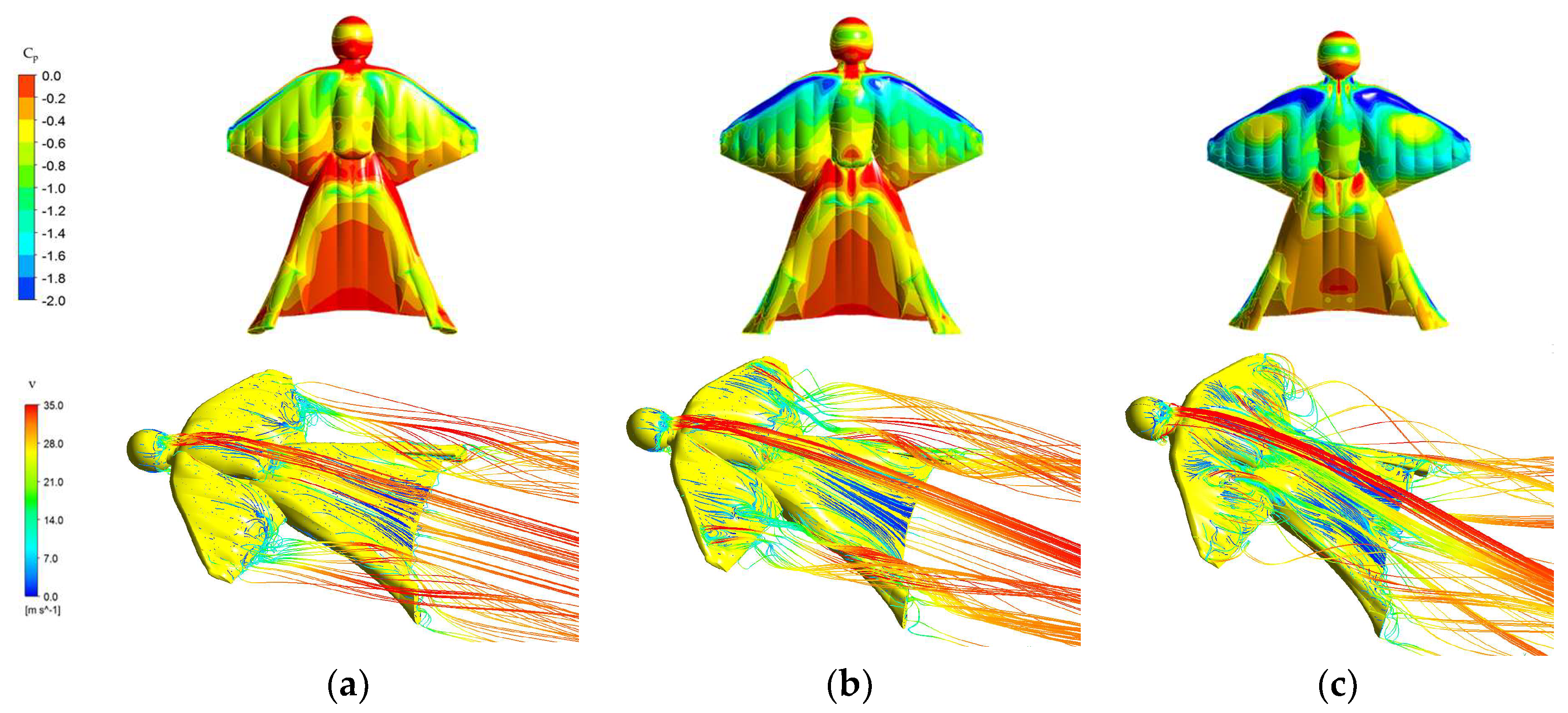
Figure 5 reports the time-averaged pressure coefficient Cp on the wingsuit surface and 3D streamlines. The pressure on the top surface of the wingsuit is reduced near the edges of the arm wings and increased across the middle of the body. The separated flow curls around the edges. The suction peak created by vortices on the shoulders enhances lift but also contributes to increased drag. Figure 5 also highlights the changes in the flow when increasing the angle of attack from 5° to 25°. The suction peak grows and shifts upstream. The suction peak is less noticeable at 5° and 15°, in contrast to 25°, where it is more detectable. A strong vortex is visible around the arm wings (identified by the negative peak of Cp on the shoulders). A similar but smaller vortex is present along the leg wing. The pressure coefficient seems more homogenous in the area of the leg wing for each angle of attack. Increasing the angle of attack, the pressure difference in the region of the leg wing decreases markedly. This results in more lift, and more drag.
3.2. Lift and Drag Forces
Different variants of the wingsuit were simulated to investigate how the accuracy of the geometric representation of the wingsuit affects the aerodynamic computations. The basic geometry with simplified arm and leg wings and the improved wingsuit geometry with more details considering the thickness and the shape of the wings caused by the inflations are shown in Table 1. The results obtained from the wind tunnel experiments are now compared to the simulation data.
Lift and drag forces are the components of the resulting aerodynamic force affecting the flying body, either perpendicularly or in parallel to the free stream velocity [13] with the lift to drag ratio being one of the key parameters for aerodynamic efficiency. Lift and drag forces increase with the angle of attack in both, experiment and simulation. The experimental measurement technique has an error of ±15 N but the difference between the calculated data is much larger. As seen in Table 1 the lift forces are similar to the experimental data. Drag forces, on the other hand, are underestimated to a great extent.
In the present case, the more detailed description of the wingsuit shape does not result in better coincidence with the experiments, unfortunately. The origin of this discrepancy cannot be conclusively determined at this stage. The position of the aviator in the wind tunnel is difficult to determine and to hold precisely during the measurements. Furthermore, the flow field is very complex and highly depends on the separation point on the geometry. Here, the rounded arms and legs pose substantial problems for the simulation as they allow a relatively wide range of positions where the flow can separate. The flow addressed here is, by its geometry and by its nature, extremely difficult to compute with state-of-the-art RANS models. Further studies are required to identify the sources of deviation, in both experiment and simulation, and to improve upon these in the simulations.
4. Conclusions
The contribution discusses the challenges and potentials of the design phase and the CFD simulations of a wingsuit. A process chain from scanned data to CAE and CFD simulations and up to the subsequent production is proposed, and a systematic aerodynamic development was performed using a commercially available tool. While at present the results still deviate somewhat between the experiments and the simulations this approach has the potential to allow the assessment of the functionality and subsequent optimization. Obviously, the integrated software approach proposed here is applicable to other kinds of sports as well.
Conflicts of Interest
The authors declare no conflict of interest.
References
- Pernpeintner, A.; Winkler, A. Lessons learned from the aerodynamic shape development process of a bobsleigh. Procedia Eng. 2010, 2, 2407–2412. [Google Scholar] [CrossRef]
- Chowdhury, H.; Alam, F.; Subic, A. Aerodynamic performance evaluation of sports textile. Procedia Eng. 2010, 2, 2517–2522. [Google Scholar] [CrossRef]
- Latchman, R.; Pooransingh, A. Aerodynamic Analysis of a Ski Jumper: A CFD Approach. In Proceedings of the 2016 COMSOL Conference, Boston, MA, USA, 5–7 October 2016. [Google Scholar]
- Meile, W.; Reisenberger, E.; Mayer, M.; Schmölzer, B.; Müller, W.; Brenn, G. Aerodynamics of ski jumping: Experiments and CFD simulations. Exp. Fluids 2006, 41, 949–964. [Google Scholar] [CrossRef]
- Barth, T.J.; Griebel, M.; Keyes, D.E.; Roose, D.; Schlick, T.; Nieminen, R.M. Lecture Notes in Computational Science and Engineering; Springer: Berlin/Heidelberg, Germany, 2016. [Google Scholar]
- Gardan, N.; Schneider, A.; Polidori, G.; Trenchard, H.; Seigneur, J.M.; Beaumont, F.; Fourchet, F.; Taiar, R. Numerical investigation of the early flight phase in ski-jumping. J. Biomech. 2017, 59, 29–34. [Google Scholar] [CrossRef] [PubMed]
- Winkler, A.; Pernpeintner, A. Improving the Performance of a Bobsleigh by Aerodynamic Optimization (P212). Eng. Sport 2008, 7, 329–338. [Google Scholar]
- Winkler, A.; Pernpeintner, A. Automated aerodynamic optimization of the position and posture of a bobsleigh crew. Procedia Eng. 2010, 2, 2399–2405. [Google Scholar] [CrossRef]
- Ubbens, H.H.; Dwight, R.P.; Sciacchitano, A.; Timmer, N. Some Results on Bobsleigh Aerodynamics. Procedia Eng. 2016, 147, 92–97. [Google Scholar] [CrossRef]
- Berry, M.; Las Fargeas, J.; Blair, K.B. Wind tunnel testing of a novel wingsuit design. Procedia Eng. 2010, 2, 2735–2740. [Google Scholar] [CrossRef]
- Furman, A.; Breitsamter, C. Chapter 21—Experimental Investigations on the VFE-2 Configuration at TU Munich, Germany; Summary Report of Task Group AVT-113; NATO Science and Technology Organization: Neuilly sur Seine, France, 2009. [Google Scholar]
- Zwerger, C.; Hickel, S.; Breitsamter, C.; Adams, N.A. Wall-modeled large-eddy simulation of the VFE-2 delta wing. In Proceedings of the 33rd AIAA Applied Aerodynamics Conference, Dallas, TX, USA, 22–26 June 2015; pp. 1–14. [Google Scholar]
- John, J.; Anderson, D. Fundamentals of Aerodynamics, 5th ed.; McGraw-Hill Education: New York, NY, USA, 2009. [Google Scholar]
- Reichert, U.; Krzywinski, S.; Siegmund, J.; Hildebrand, V.; Schubert, A. Entwicklung und Erprobung von Flügelanzügen mit Nutzerzentrierten und Leistungsorientierten Eigenschaften zum Fallschirmspringen; KF 2048924AG1, KF 2944601AG; Abschlussbericht: TU Dresden, Germany, 2014. [Google Scholar]
- Ansari, N.; Krzywinski, S. 3D design and simulation of a one-piece wingsuit for aerodynamic optimization of the flight behavior. In Proceedings of the 1st International Conference in Sports Science & Technology (ICSST), Singapore, 11–12 December 2014. [Google Scholar]
- Ansari, N.; Krzywinski, S.; Fröhlich, J. 3D design and simulation methods for the development of a wingsuit. In Proceedings of the AUTEX Meeting 2017, Clotech, Lodz, 11 October 2017; p. 10. [Google Scholar]
Figure 1.
Comparison between experiment and simulation with the SST turbulence model for Re = 1 × 10⁶, M = 0.07, α = 13°, MRLE: (a) Axial velocity distribution, (b) Wall streamlines. The left parts of the pictures represent the experimental data from [11], the right parts the simulation data.
Figure 1.
Comparison between experiment and simulation with the SST turbulence model for Re = 1 × 10⁶, M = 0.07, α = 13°, MRLE: (a) Axial velocity distribution, (b) Wall streamlines. The left parts of the pictures represent the experimental data from [11], the right parts the simulation data.

Figure 2.
Velocity streamlines and comparison of the pressure coefficient between experimental data [11] and simulations using the SST model for Re = 1 × 10⁶, M = 0.07, α = 13°: (a) SLE; (b) MRLE.
Figure 2.
Velocity streamlines and comparison of the pressure coefficient between experimental data [11] and simulations using the SST model for Re = 1 × 10⁶, M = 0.07, α = 13°: (a) SLE; (b) MRLE.

Figure 3.
Wingsuit jumper in different positions during the wind tunnel experiments at ILR [14].
Figure 3.
Wingsuit jumper in different positions during the wind tunnel experiments at ILR [14].

Figure 4.
Model development of the wingsuit (arm and leg wing)—flat position.

Figure 5.
Pressure contours on the wingsuit (top view) and 3D streamlines in the flow colored with the magnitude of the velocity for flat position at different angles of attack; (a) 5°; (b) 15°, (c) 25°.
Figure 5.
Pressure contours on the wingsuit (top view) and 3D streamlines in the flow colored with the magnitude of the velocity for flat position at different angles of attack; (a) 5°; (b) 15°, (c) 25°.


Table 1.
Comparison of lift (L) and drag (D) forces between wind tunnel experiments and simulations for flat position at angles of attack α of 5°, 15° and 25°.
Table 1.
Comparison of lift (L) and drag (D) forces between wind tunnel experiments and simulations for flat position at angles of attack α of 5°, 15° and 25°.
| α [°] | Experiments | Simulation Results of the Wingsuit | ||||||
| Simplified |  | Improved |  | |||||
| L [N] | D [N] | L [N] | D [N] | L [N] | D [N] | |||
| 5 | 467 | 311 | 340 | 90 | 356 | 96 | ||
| 15 | 549 | 348 | 638 | 206 | 656 | 200 | ||
| 25 | 594 | 384 | 730 | 330 | 840 | 380 | ||
Publisher’s Note: MDPI stays neutral with regard to jurisdictional claims in published maps and institutional affiliations. |
© 2018 by the authors. Licensee MDPI, Basel, Switzerland. This article is an open access article distributed under the terms and conditions of the Creative Commons Attribution (CC BY) license (https://creativecommons.org/licenses/by/4.0/).
Share and Cite
MDPI and ACS Style
Ansari, N.; Krzywinski, S.; Fröhlich, J. Towards a Combined CAD and CFD Development Process of a Wingsuit. Proceedings 2018, 2, 228. https://doi.org/10.3390/proceedings2060228
AMA Style
Ansari N, Krzywinski S, Fröhlich J. Towards a Combined CAD and CFD Development Process of a Wingsuit. Proceedings. 2018; 2(6):228. https://doi.org/10.3390/proceedings2060228
Chicago/Turabian StyleAnsari, Nazanin, Sybille Krzywinski, and Jochen Fröhlich. 2018. "Towards a Combined CAD and CFD Development Process of a Wingsuit" Proceedings 2, no. 6: 228. https://doi.org/10.3390/proceedings2060228