The Influence of the Phase Difference between the Crank Angle of the Pilot and that of the Stoker on the Drag Acting on a Tandem Bike †


Department of Education, Art and Science, Yamagata University, Yamagata 990-8560, Japan
*
Author to whom correspondence should be addressed.
†
Presented at the 12th Conference of the International Sports Engineering Association, Brisbane, Queensland, Australia, 26–29 March 2018.
Proceedings 2018, 2(6), 209; https://doi.org/10.3390/proceedings2060209
Published: 12 February 2018
(This article belongs to the Proceedings of The 12th Conference of the International Sports Engineering Association)
Abstract
:Two wind tunnel experiments were carried out to investigate the drag acting on a tandem bike. One experiment involved measurement of the drag acting on two full-scale human models on a tandem. These two human models can pedal the tandem. In the other experiment, two oscillating cylinders were used as a simplified model of the legs of the pilot and the stoker. These were arranged to represent the legs of the riders on a tandem. Measurements of the drag on this model were made. It was found that the drag decreases when the crank angle of the stoker’s pedal is delayed with respect to the pilot’s pedal.
1. Introduction
Tandem bikes are for visually impaired riders. The pilot (sighted rider) will always be on the front, with the stoker (visually impaired rider) on the back. In general, the pilot is a professional cyclist. Since both riders’ pedals are connected via sprockets and chains, the stoker should have the ability to cycle as proficiently as the professional cyclist.
The drag acting on a tandem bike has been experimentally investigated. Two full-scale human models were employed for the wind tunnel tests. Motor power was transmitted to the legs of the two models via pulleys and a chain. The pedaling model was developed at Monash University [1]. Two full scale models which could pedal the tandem bike was developed in this paper. Since these two human models can pedal the tandem, the influence of the phase difference between the crank angle of the pilot and that of the stoker on the drag acting on the tandem can be investigated.
It was reported that the dominant mechanism affecting drag is due to large changes in the flow structure on the basis of three-dimensional flows around a full-scale cyclist mannequin [2]. Two characteristic flow regimes are identified, corresponding to symmetrical low-drag and asymmetrical high-drag regimes, in which the primary feature of the wake is shown to be a large trailing streamwise vortex pair, orientated asymmetrically in the center plane of the mannequin. On the other hand, this paper did not pay attention to the asymmetrical effect in the center plane of the mannequin, but the influence of the phase difference between the crank angle of the pilot and that of the stoker. It was found that the drag acting on the tandem bike with full-scale pedaling model depends on the phase difference as will be shown later. In order to examine the effect of the phase difference, measurements were also made on two oscillating cylinders, considered to be a simple model representing the legs of the pilot and the stoker. These were arranged in the same way as the legs of riders on a tandem.
2. Methods
Two series of wind tunnel tests were carried out. One was a test with the full-scale model of a tandem bike, and the other was with the two oscillating cylinders in a tandem arrangement.
2.1. Full-Scale Model
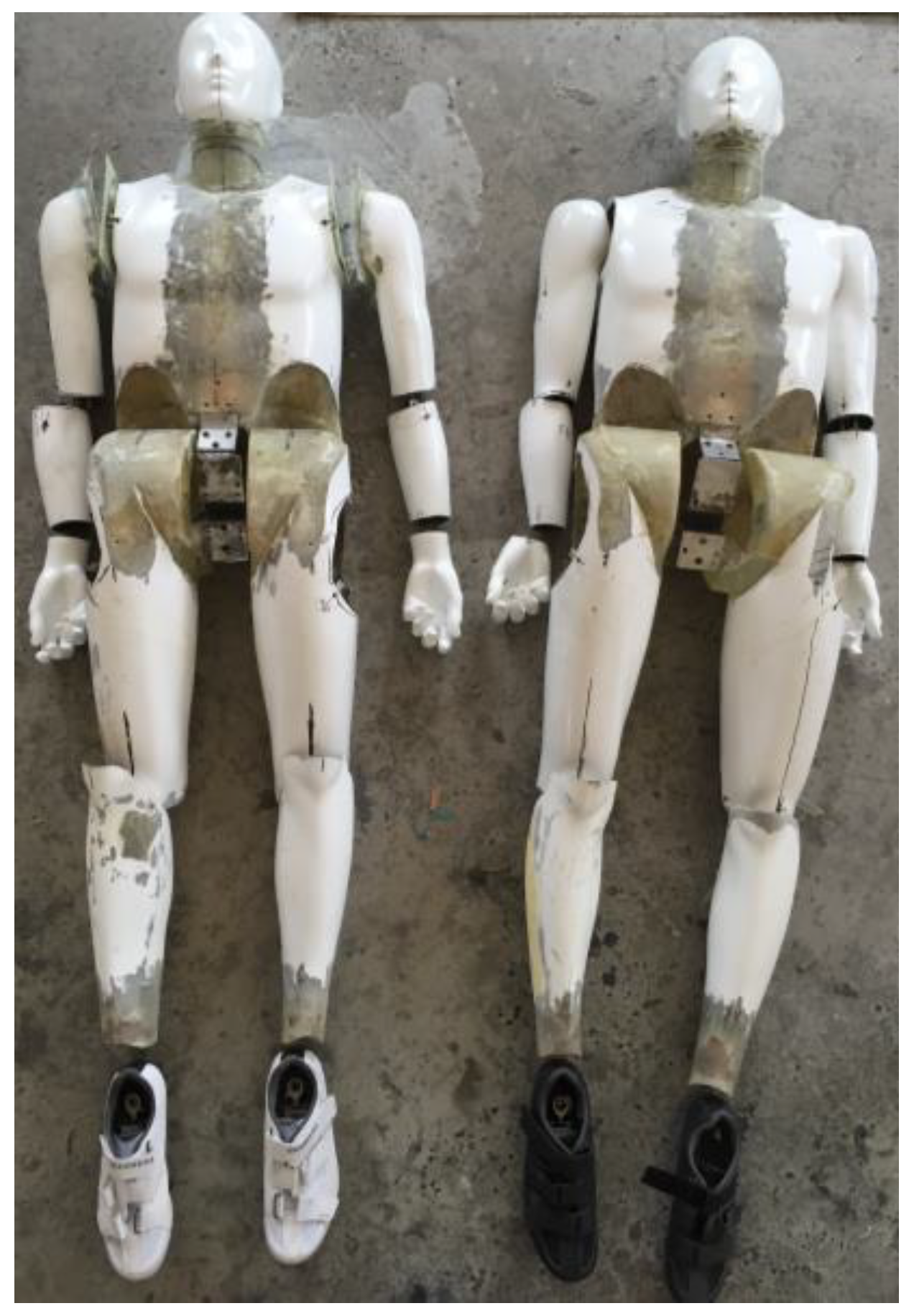
The two pedaling models are shown in Figure 1. The height was adjusted to 1.62 m, which was defined as the height of Japanese Paralympians. Commercially available mannequins made of fiber-reinforced plastic were used for the riders. In order that the joints at the neck, shoulders, elbows, wrists, waist, knees and ankles could move, cuts were made at the joints and mechanisms inserted. It should be noted that these mannequins did not have any active mechanism to make them move. Movement of the mannequins was forced through the pedal by the motor shown in Figure 2b.
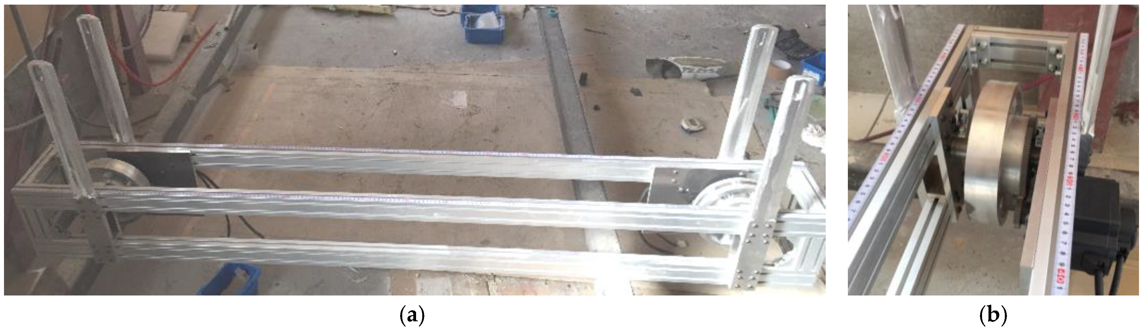
The frame for supporting the tandem bike and the two pedaling models in the wind tunnel is shown in Figure 2. The side view is in Figure 2a, while a magnified picture around the pulley and motor for the front wheel is shown in Figure 2b. The left pulley in Figure 2a is for the front wheel, while the right pulley is for the rear wheel. The wheels were rotated via the pulleys by motors. The struts have a NACA0012 airfoil cross section. Since the distance between both struts is adjustable, this frame is usable for a normal (single) bike.
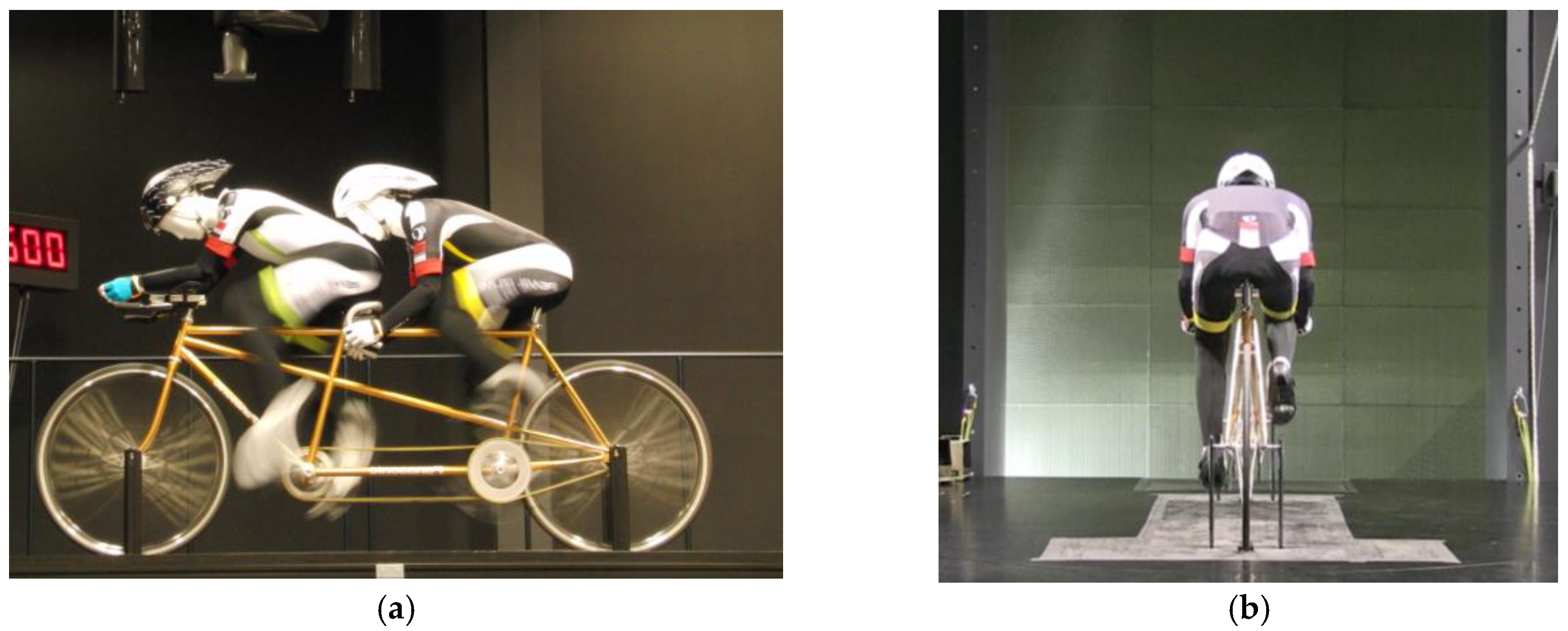
Wind tunnel tests were carried out in the Japan Institute of Sports Science as shown in Figure 3. A commercially available tandem bike was employed (Panasonic). The wind tunnel is an Eiffel type, and the size of the outlet is 2.5 m by 3.0 m. The wind direction is from the left to the right. As can be seen from the side view, both the pilot and the stoker are pedaling. The drag was measured with a six-component balance (LMC-61263, Nissho electric).
The wind speed was set at 50 km/h. The maximum speed of 50 km/h corresponds with the average speed of top riders. The angular velocity of pedaling was adjusted with the wind speed. However, since the models vibrated excessively, which compromise measurement results, at the maximum wind speed of 50 km/h, the angular velocity of pedaling was set at 1.7 rev./s. which corresponds with a speed of 45 km/h. The diameter of the tire was 0.34 m, while the gear ratio was 3.53. The angle of inclination of both riders’ torsos were set at a constant value of 35° from the horizontal, which is a typical value in practice.
2.2. Two Oscillating Cylinders in the Tandem Arrangement
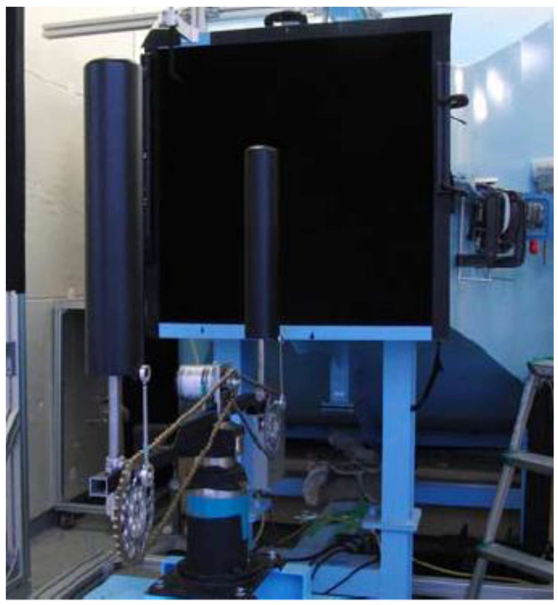
The two oscillating cylinders in the tandem arrangement were experimentally investigated as shown in Figure 4. The primary aim of this experiment was to verify the idea of the flow, which will be shown later (Figures 6 and 7). In this arrangement, these cylinders were considered to be a simplified model of the legs of the pilot and the stoker. Both cylinders can oscillate in the vertical direction. They were driven by a motor with a spin rate set at 450 rev./s, which corresponds to an oscillating period of 0.4 s (2.5 Hz) in the vertical direction. The oscillating frequency of cylinders was higher than the pedaling frequency of the full-scale model. This is because of the less torque characteristic of the motor at the low angular velocity. The oscillating frequency of 2.5 Hz is the lowest possible limit in this experimental set-up. In order to make the frequency of pedaling less than 2 Hz (The practical pedaling frequency is less than 2 Hz [2]), the present motor should be replaced for the more powerful motor in the future.
Both cylinders are connected to the motor via gears and chains, so that they oscillate at the same frequency. Since there were 36 gears on the sprocket, it was possible to acquire the data with phase difference intervals of 10 degrees. In this case, the data were acquired with a phase difference interval of 30 degrees. The diameters of both cylinders were 80 mm, the distance between them was 800 mm, the amplitude of the oscillation was 100 mm, and the wind speed was set at 14 m/s (50 km/h).
3. Results and Discussions
Drag Measurements
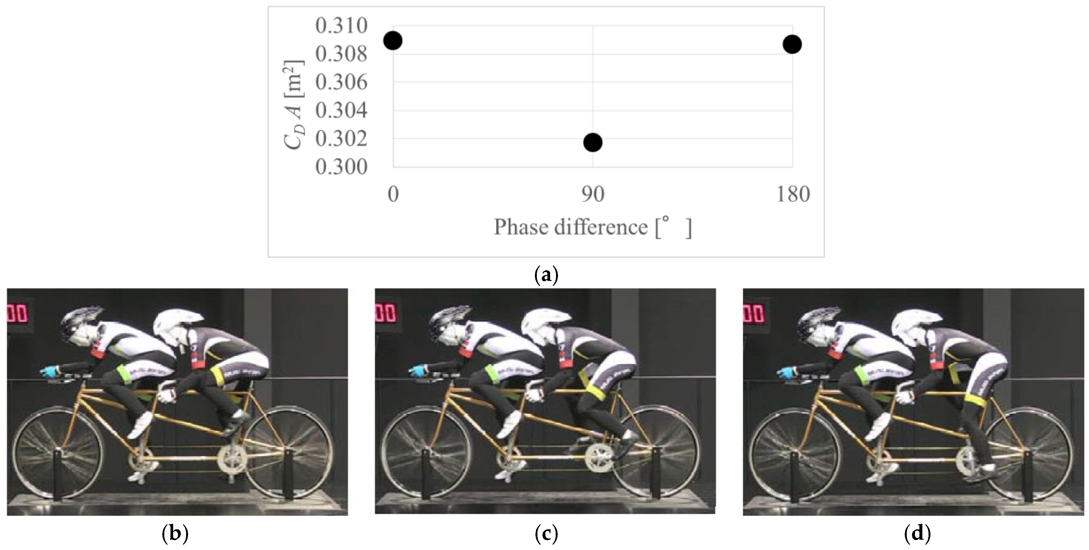
The dependence of the phase difference between the crank angle of the pilot and that of the stoker on the CDA is shown in Figure 5. The CDA is the drag divided by the dynamic pressure. The drag is the averaged values for 8 cycles (about 5 s) with a sampling rate of 1 KHz. Therefore, it was independent of the start or end positions of legs. Although the repeatability of the raw oscillating data was good, the measuring time should be longer in the future. Figure 5b–d are snapshots during the run.
At 0 degrees (Figure 5b), both riders left legs are at the top. At 90 degrees (Figure 5c), the left leg of the stoker is delayed by 90 degrees. At 180 degrees (Figure 5d), the left leg of the stoker is delayed by 180 degrees (the crank angles of the riders are opposite each other). Off course, both riders pedal during the run.
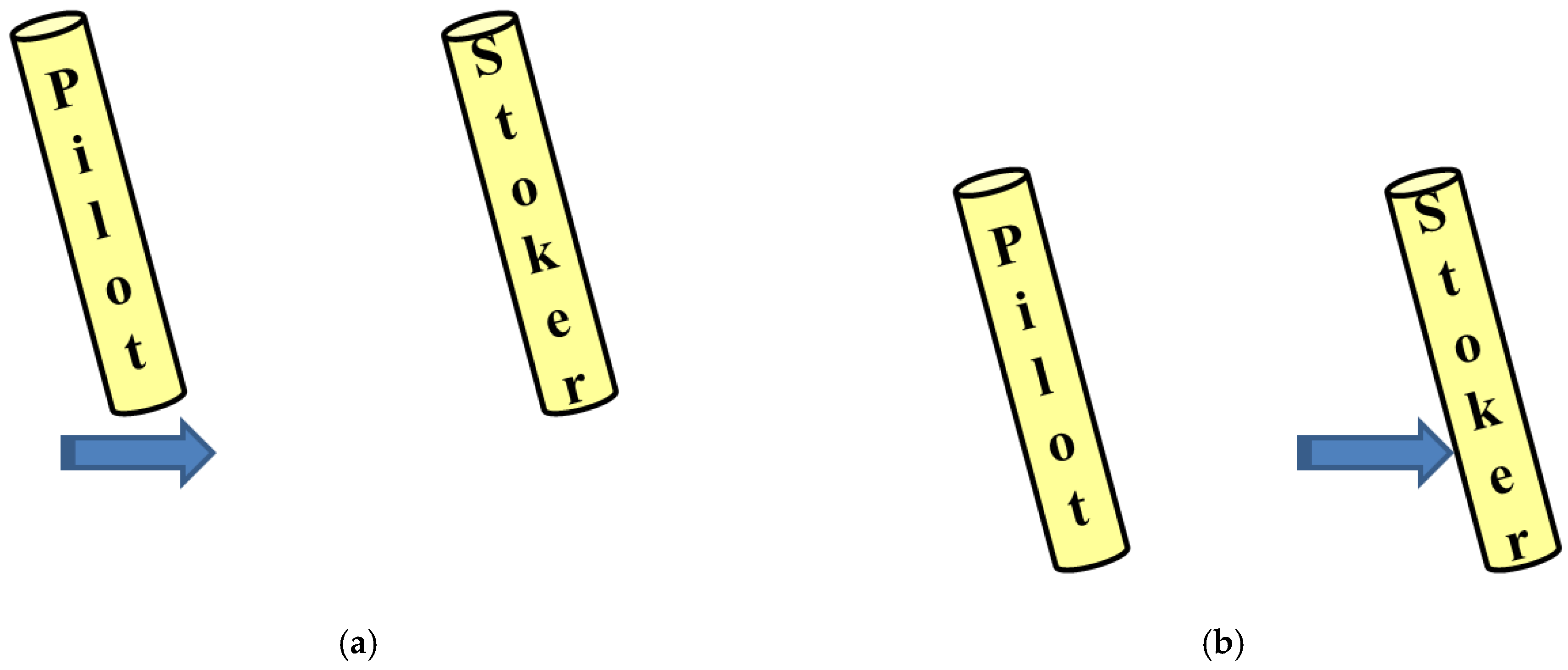
The wind passing just below the sole of the pilot’s foot (Figure 6a) blows against the stoker’s leg (Figure 6b).
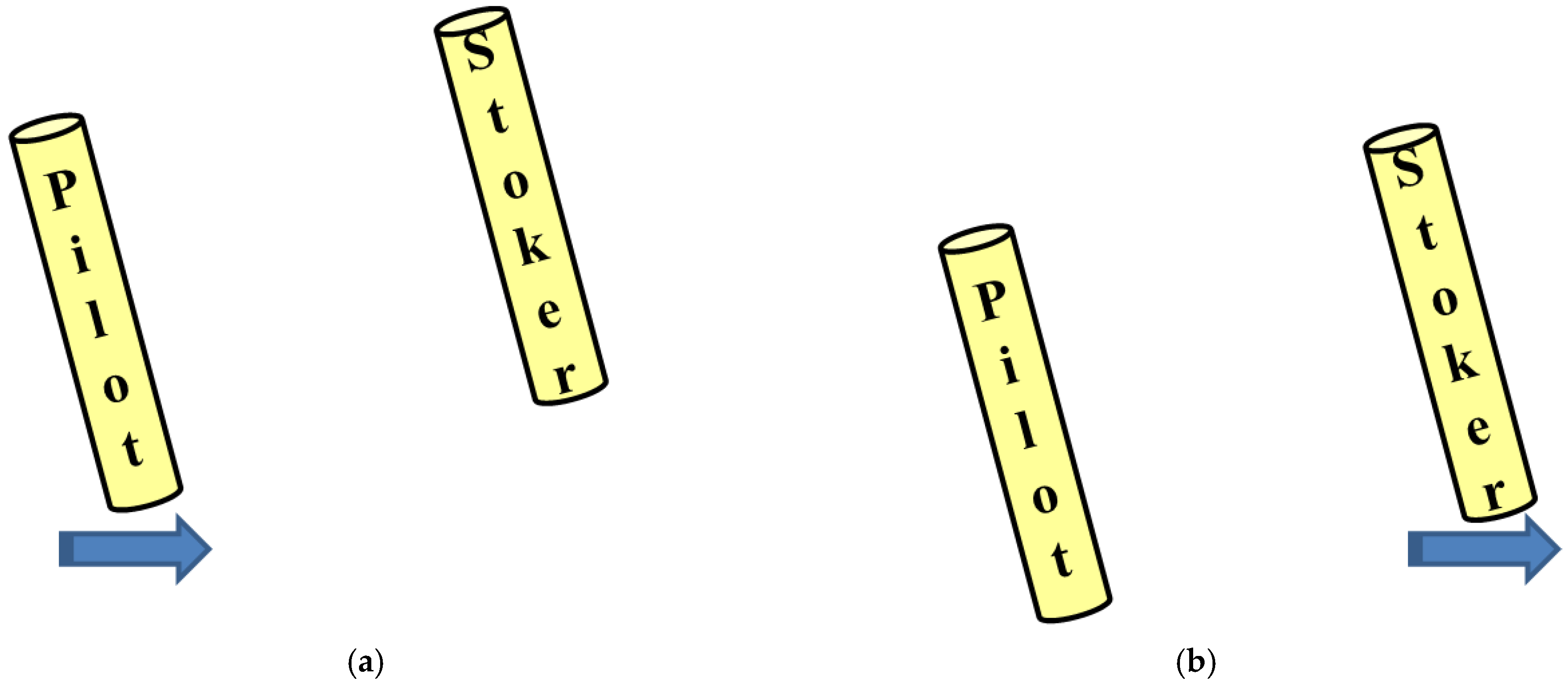
The wind passing just below the sole of the pilot’ foot (Figure 7a) also bypasses the stoker’s leg (Figure 7b).
It was found that the drag at 90° was the smallest of the three cases. The difference in drag might be due to whether or not the wind blows against the stoker’s leg. At 0°, the wind passing just below the sole of the pilot’s foot (Figure 6a) blows against the stoker’s leg (Figure 6b) when both riders’ legs move downward by pedaling. Therefore, the drag is relatively large at 0°. On the other hand, at 90°, the wind passing just below the sole of the pilot’s foot (Figure 7a) also bypasses the stoker’s leg (Figure 6b). Therefore, the drag is small. The finer resolution of the drag measurements on the phase difference is required in the future.
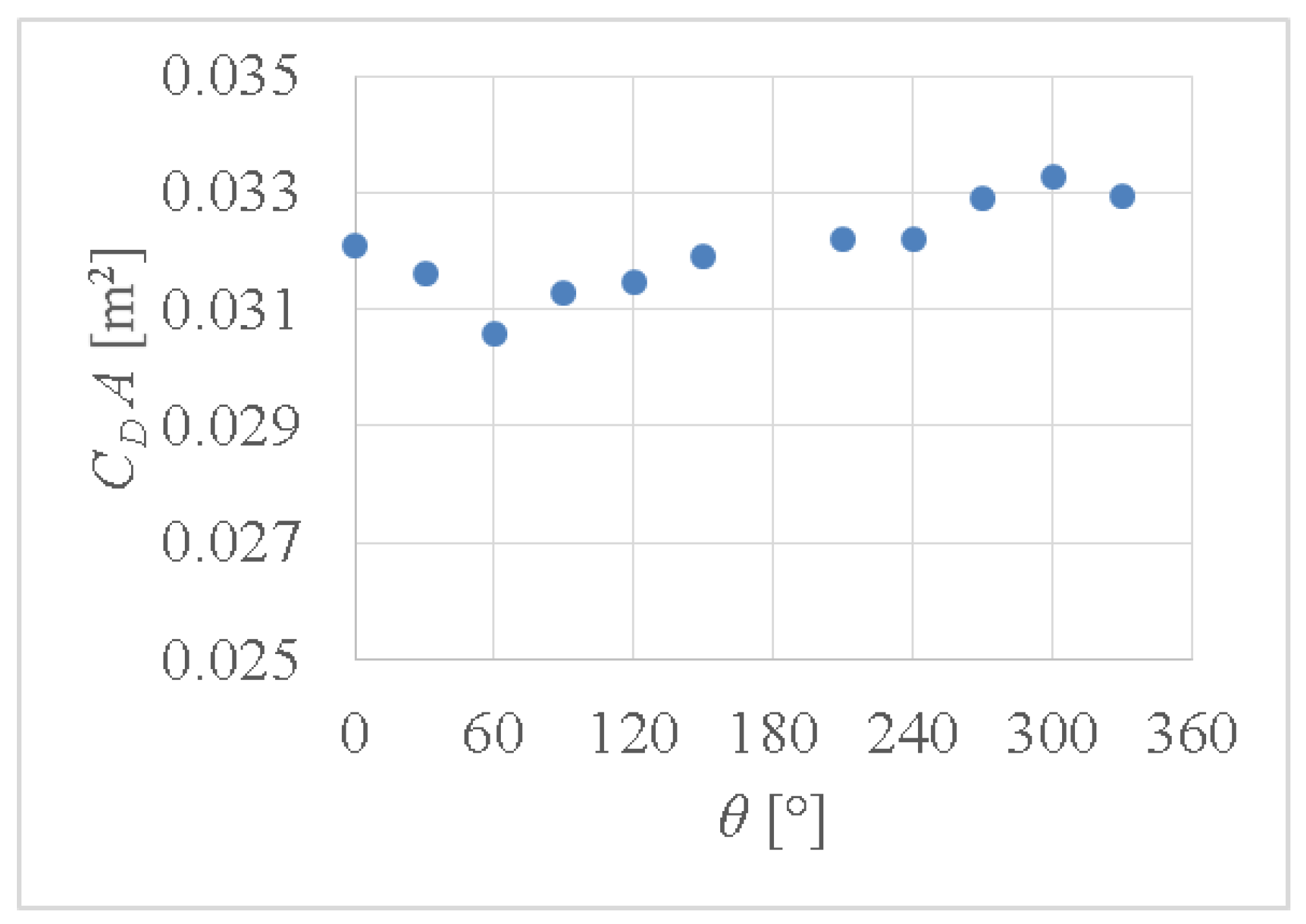
In order to examine the flow images shown in Figure 6 and Figure 7, the drag acting on the two oscillating cylinders shown in Figure 4 was measured at a wind speed of 14 m/s. The results are shown in Figure 8. The ordinate is CDA, which is the drag divided by the dynamic pressure, while the abscissa, θ, is the phase difference between the cylinders. For example, a phase difference of 0 degrees means that both cylinders oscillate synchronously, while a phase difference of 90 degrees means that the cylinder on the downstream side is delayed by 90 degrees. At 330 degrees, the cylinder on the downstream side leads by 30 degrees. It was found that the drag depends on the phase difference. It can be seen that CDA decreases with increasing θ up to 60 degrees, and then increases with increasing θ. The values at more than 180 degrees are larger than the value at 0 degrees. Therefore, it can be concluded that the drag decreases when the cylinder on the downstream side is delayed, while it increases when the cylinder on the downstream side leads. In other words, the drag decreases when stoker’s crank angle is delayed to the pilot’s crank angle.
4. Conclusions
The drag acting on a tandem-bike was experimentally investigated in a wind tunnel. The conclusion is summarized as follows: The drag acting on the tandem bike is influenced by the phase difference between the crank angle of the pilot and that of the stoker. The drag decreases when the stoker’s crank angle is delayed in the ranges between 0 and 180 degrees. Therefore, the phase difference is the important setting in the case of the tandem bike.
Acknowledgments
This work is supported by a Grant-in-Aid for Scientific Research (A), No. 15H01824, Japan Society for the Promotion of Science.
References
- Barry, N.; Burton, D.; Sheridan, J.; Thompson, M.; Brown, N.A.T. An analysis of the wake of pedalling cyclists in a tandem Formation. Procedia Eng. 2016, 147, 7–12. [Google Scholar] [CrossRef]
- Crouch, T.N.; Burton, D.; Brown, N.A.T.; Thompson, M.C.; Sheridan, J. Flow topology in the wake of a cyclist and its effect on aerodynamic drag. J. Fluid Mech. 2014, 748, 5–35. [Google Scholar] [CrossRef]
Figure 1.
Two full-scale models.

Figure 2.
Frame for supporting a tandem bike: (a) Side view; (b) Pulley and motor.

Figure 3.
Wind tunnel test of a tandem bike. Both mannequins can pedal: (a) Side view; (b) Back view.
Figure 3.
Wind tunnel test of a tandem bike. Both mannequins can pedal: (a) Side view; (b) Back view.

Figure 4.
Two oscillating circular cylinders in a tandem arrangement.

Figure 5.
CDA as a function of the phase difference between the crank angle of the pilot and that of the stoker: (a) Drag vs phase difference; (b) 0 degrees; (c) 90 degrees; (d) 180 degrees.
Figure 5.
CDA as a function of the phase difference between the crank angle of the pilot and that of the stoker: (a) Drag vs phase difference; (b) 0 degrees; (c) 90 degrees; (d) 180 degrees.

Figure 6.
Schematics illustrating the flow around both legs at 0 degrees (Figure 5b). The wind direction is from the left to the right. (a) both riders’ legs are at the top; (b) both riders’ legs are at the bottom.
Figure 6.
Schematics illustrating the flow around both legs at 0 degrees (Figure 5b). The wind direction is from the left to the right. (a) both riders’ legs are at the top; (b) both riders’ legs are at the bottom.

Figure 7.
Schematics illustrating the flow around both legs at 90 degrees (Figure 5c). The wind direction is from the left to the right. (a) the stoker’s leg is at the top (the pilot’s leg is in front); (b) the pilot’s leg is at the bottom.
Figure 7.
Schematics illustrating the flow around both legs at 90 degrees (Figure 5c). The wind direction is from the left to the right. (a) the stoker’s leg is at the top (the pilot’s leg is in front); (b) the pilot’s leg is at the bottom.

Figure 8.
CDA vs. phase difference at 14 m/s.

Publisher’s Note: MDPI stays neutral with regard to jurisdictional claims in published maps and institutional affiliations. |
© 2018 by the authors. Licensee MDPI, Basel, Switzerland. This article is an open access article distributed under the terms and conditions of the Creative Commons Attribution (CC BY) license (https://creativecommons.org/licenses/by/4.0/).
Share and Cite
MDPI and ACS Style
Seo, K.; Eda, S. The Influence of the Phase Difference between the Crank Angle of the Pilot and that of the Stoker on the Drag Acting on a Tandem Bike. Proceedings 2018, 2, 209. https://doi.org/10.3390/proceedings2060209
AMA Style
Seo K, Eda S. The Influence of the Phase Difference between the Crank Angle of the Pilot and that of the Stoker on the Drag Acting on a Tandem Bike. Proceedings. 2018; 2(6):209. https://doi.org/10.3390/proceedings2060209
Chicago/Turabian StyleSeo, Kazuya, and Satoshi Eda. 2018. "The Influence of the Phase Difference between the Crank Angle of the Pilot and that of the Stoker on the Drag Acting on a Tandem Bike" Proceedings 2, no. 6: 209. https://doi.org/10.3390/proceedings2060209