Modelling and Experimental Analysis of a Magnetic Material Actuator: Towards Wireless Implantable Devices †


Mechanical Engineering, The University of Auckland, Auckland 1010, New Zealand
*
Author to whom correspondence should be addressed.
†
Presented at the Eurosensors 2017 Conference, Paris, France, 3–6 September 2017.
Proceedings 2017, 1(4), 368; https://doi.org/10.3390/proceedings1040368
Published: 21 August 2017
(This article belongs to the Proceedings of Proceedings of Eurosensors 2017, Paris, France, 3–6 September 2017)
Abstract
:This paper presents a wireless diaphragm actuator and focuses on a lumped parameter grey-box model capable of simulating actuation displacement. Here, modelling aims to provide further insight into this smart material actuator and help facilitate design into new implantable applications. Model parameters were calibrated to a prototype actuator using experimental data and a genetic algorithm optimisation. The model was validated against experimental data and showed a good ability to simulate both static and dynamic diaphragm displacement.
1. Introduction
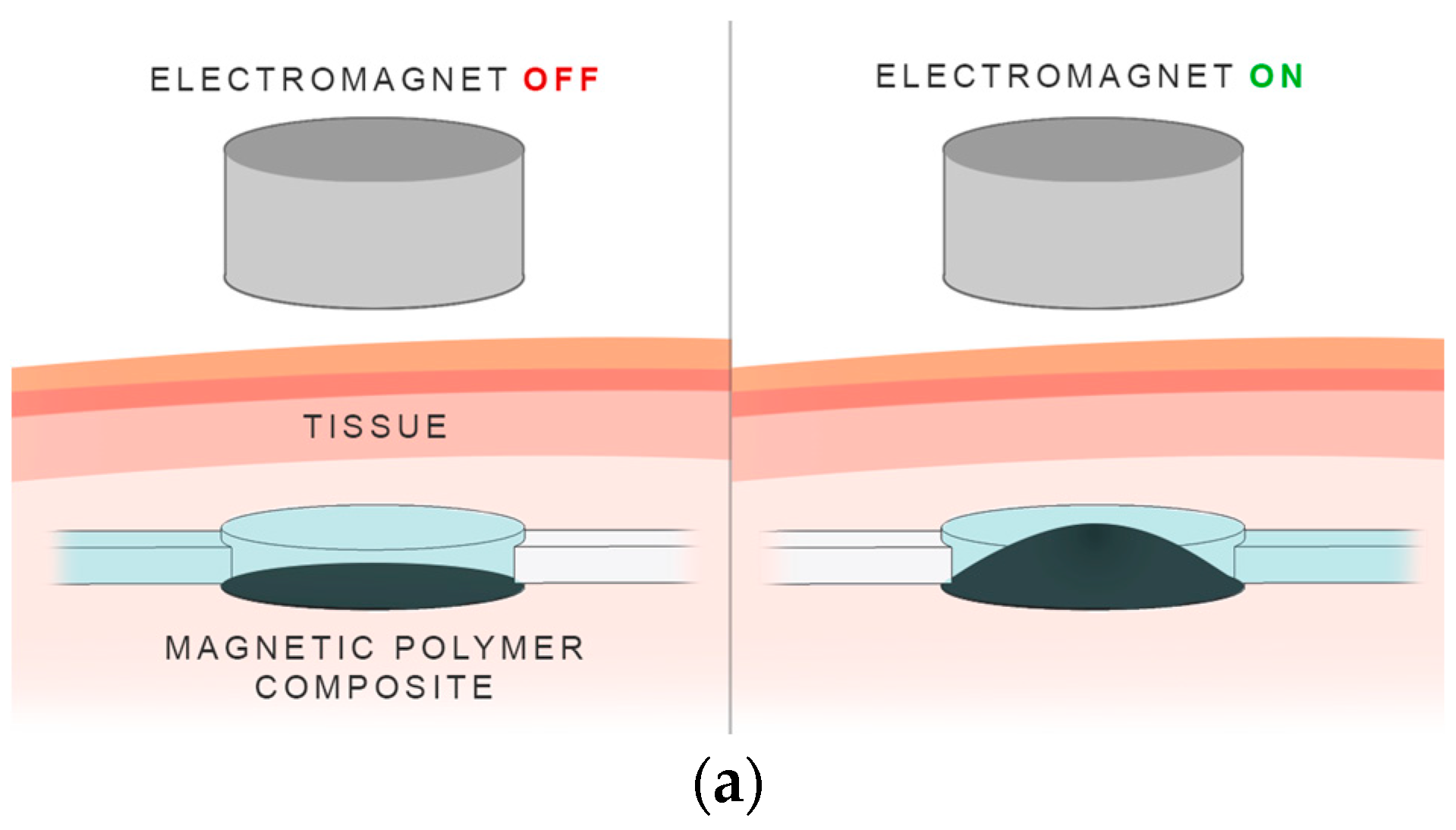
Biomedical devices are a promising application where the use of smart material actuators could lead to innovation. Here, we present a material actuator made from a magnetic polymer composite. The proposed actuator is wirelessly actuated and does not require onboard circuitry or power supply to operate. The significance of this allows for inherently safer implantable devices while also reducing design complexity. Previous work on magnetic polymer actuators is limited to large dipole electromagnet or permanent magnet configurations [1,2]. Here, the actuator is configured as a clamped diaphragm and actuated by a single external electromagnet, as illustrated in Figure 1. This paper focuses on the derivation and validation of an actuation model to simulate diaphragm displacement. A grey-box modelling approach was utilised to avoid the challenges of quantifying magnetic properties of polymer composites, such as magnetic permeability and magnetisation. This method allows specific actuator characteristics, such as wireless distance and maximum displacement, to be modelled without the need to define the magnetic properties of the system explicitly.
2. Materials and Methods
2.1. Diaphragm Fabrication
The magnetic diaphragm is composed of a magnetic filler (Synthetic Fe3O4 microparticles, Inoxia Ltd., Cranleigh, UK) embedded within an elastomeric silicone matrix (Ecoflex 00-30, Smooth-On, Macungie, PA, USA). The two constituents were mixed using an ultrasonic homogeniser (VCX130 Vibra-Cell Processor, Sonics & Materials Inc., Newtown, CT, USA). The resulting solution was cast into a mould, degassed in a vacuum chamber and left to cure for four hours at room temperature.
The cured diaphragm had a diameter and thickness of 65 mm and 1.5 mm, respectively. The sample was later pre-strained to 10% to ensure a uniform surface stress profile. The magnetic filler loading was 20 wt %.
2.2. Model Overview
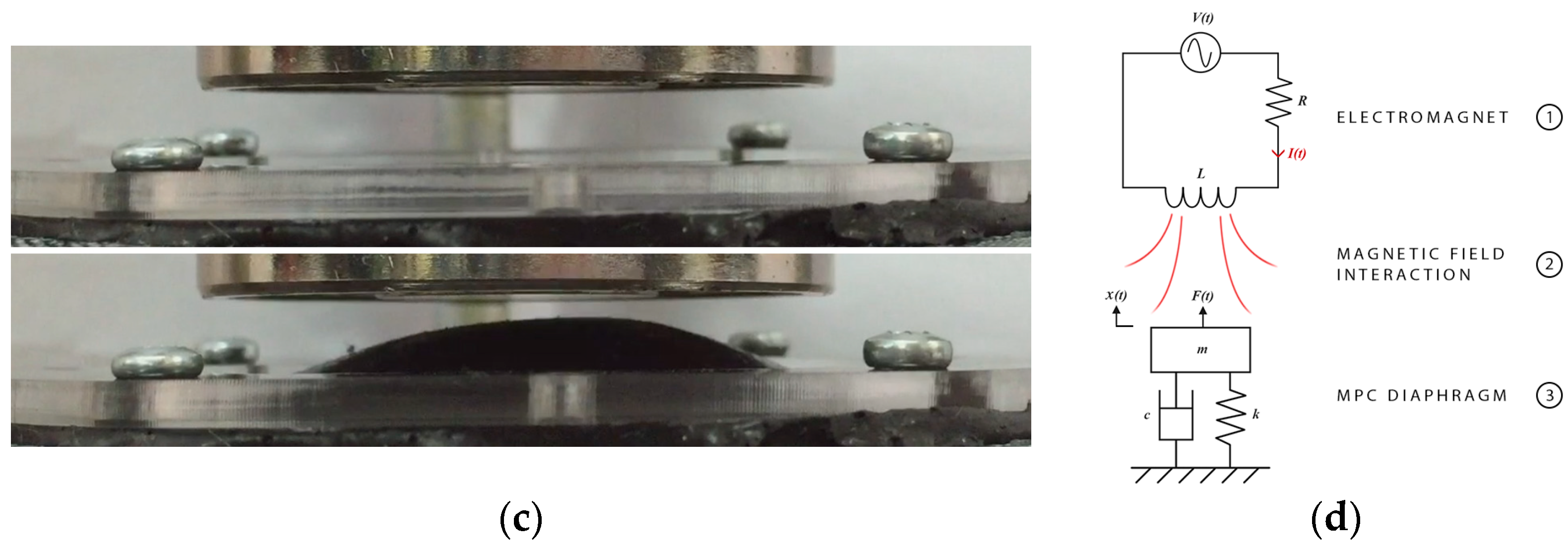
An overview of the model is illustrated in Figure 1c. The following components were modelled: the electromagnet, magnetic diaphragm and field-particle interaction. Input is electromagnet voltage, and output is maximum diaphragm displacement. The following section details each component.
2.2.1. Electromagnet
The electromagnet is approximated by a resistor-inductor (RL) circuit. The generated magnetic field is proportional to the current flowing through the coil. The following equation, derived using Kirchoff’s Voltage Law, relates the input voltage to output current,
where V(t) is input voltage, R is the resistance and L is the inductance of the electromagnet. The resulting magnetic field, Br(t), can be described using the following equation [3],
where r is the distance, along the vertical x-axis, from the electromagnet surface, a is the average radius of the electromagnet and c is the speed of light constant.
2.2.2. Magnetic Diaphragm
The mechanical behaviour of the diaphragm can be simplified to a 2nd order mass-spring-damper system. Displacement is described by the following equation,
where x is maximum diaphragm displacement, ζ is the damping ratio that characterises system response, ω0 is the natural frequency of the system and F(t) is the magnetic interaction driving force.
2.2.3. Field-Particle Interaction
The field-particle interaction induces bulk diaphragm deformation. The equivalent magnetic force acting on the polymer can be described using the following relationship,
where χm is the magnetic susceptibility of the composite, V is the magnetic volume and µ0 is the permeability of free space.
The overall differential equation relating the electromagnet current to maximum diaphragm displacement is given below,
where r0 is the initial gap distance (or wireless distance) between the surface of the electromagnet and diaphragm; determined by the physical configuration of the system. The magnetic properties of the system are lumped together into a single magneto-mechanical gain, εm.
2.2.4. Model Parameters
Table 1 provides a summary of the actuator-specific model parameters. The natural frequency was determined by analysing the frequency response to an input swept sinewave voltage signal (1 to 50 Hz). The remaining parameters were optimised using experimental data and a genetic algorithm.
2.3. Experimental Protocol
Three tests were conducted to obtain data for optimisation and model validation: step input at maximum electromagnet power (T1), another at 50% power (T2) and a 1 Hz sinusoidal input at maximum power (T3). The diaphragm was actuated using a 50 mm holding electromagnet. The maximum operating power was 48 Watts. The gap distance (r0) was set to 6.75 mm. A laser displacement sensor (LG10A65PU, Banner Engineering, Minneapolis, MN, USA) measured maximum displacement, and a current sensor (1122, Phidgets Inc., Calgary, AB, Canada) tracked electromagnet current.
A genetic algorithm (Global Optimisation Toolbox, MathWorks, Natick, MA, USA) was implemented for optimisation. To begin, R and L were optimised using measured current data from T1. The minimisation objective function was the root mean square (RMS) error between the simulated and experimental response. The remaining parameters were optimised using displacement data from T1. Here, the minimisation objective function, J, was defined by the following expression,
where Eexp, and Esim, are the peak envelopes and means of the experimental and simulated response, respectively.
3. Results
3.1. Optimisation Results
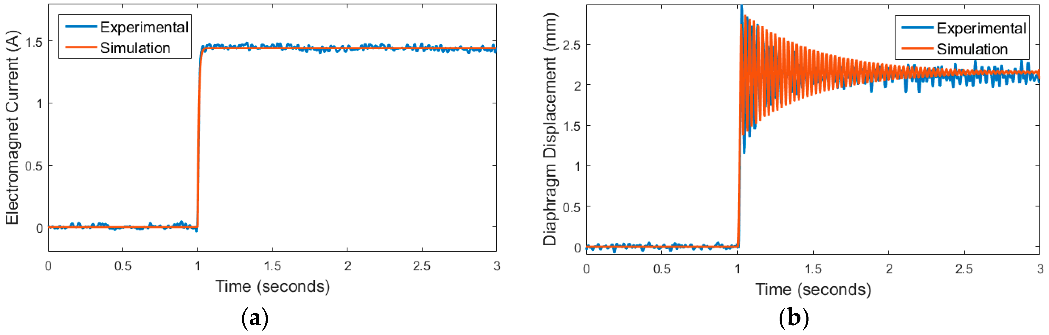
The RL circuit and 2nd order model optimisations had an RMS error of 0.018 A and 0.22 mm, respectively. The results are highlighted in Figure 2.
3.2. Validation Results
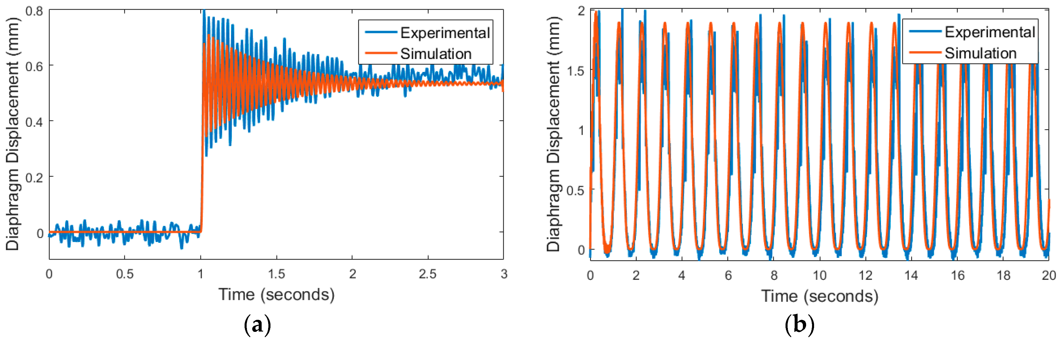
The RMS errors for T2 and T3 were 0.069 mm and 0.35 mm, respectively. The validation results are highlighted in Figure 3.
4. Discussion
The proposed grey-box modelling approach is capable of predicting maximum magnetic diaphragm displacement. Both the transient and steady-state responses are simulated well when actuated by a step input. The model also shows good dynamic performance when driven by a low-frequency sinusoidal input. This approach allows different input signals and alternative configurations (e.g., gap distance) to be simulated without needing to define the magnetic properties of the composite material explicitly. In future, the model will be expanded to account for the fringing field, and further analysis will be carried out to determine its force predicting capabilities.
Acknowledgments
This research was supported in part by the Engineers in Clinical Residence Programme administered by the “Technologies for Health” Theme from The University of Auckland.
Conflicts of Interest
The authors declare no conflict of interest. The founding sponsors had no role in the design of the study; in the collection, analyses, or interpretation of data; in the writing of the manuscript, and in the decision to publish the results.
References
- Ramanujan, R.V.; Lao, L.L. The mechanical behavior of smart magnet–hydrogel composites. Smart Mater. Struct. 2006, 15, 952. [Google Scholar] [CrossRef]
- Nguyen, V.Q.; Ramanujan, R.V. Novel coiling behavior in magnet-polymer composites. Macromol. Chem. Phys. 2010, 211, 618–626. [Google Scholar] [CrossRef]
- Jackson, J. Classical Electrodynamics, 2nd ed.; John Wiley & Sons: New York, NY, USA, 1975. [Google Scholar]
Figure 1.
(a) The proposed actuator configuration, a pumping application is shown as an example; (b) Diaphragm displacement of the magnetic polymer composite; (c) Overview of the model.
Figure 1.
(a) The proposed actuator configuration, a pumping application is shown as an example; (b) Diaphragm displacement of the magnetic polymer composite; (c) Overview of the model.


Figure 2.
Optimisation Results: (a) T1 Current (RMS = 0.018 A); (b) T1 Displacement (RMS = 0.22 mm).
Figure 2.
Optimisation Results: (a) T1 Current (RMS = 0.018 A); (b) T1 Displacement (RMS = 0.22 mm).

Figure 3.
Validation Results: (a) T2 (RMS = 0.069 mm); (b) T3 (RMS = 0.35 mm).


Table 1.
Actuator-specific model parameters.
| Symbol | Parameter | Symbol | Parameter |
|---|---|---|---|
| A 1 | Electromagnet radius | R 2 | Electromagnet resistance |
| r0 1 | Gap distance | L 2 | Electromagnet inductance |
| ω0 1 | Natural frequency | 2 | Damping ratio |
| εm 2 | Magneto-mechanical gain |
1 Measured experimentally, 2 Evaluated through genetic algorithm optimisation.
Publisher’s Note: MDPI stays neutral with regard to jurisdictional claims in published maps and institutional affiliations. |
© 2017 by the authors. Licensee MDPI, Basel, Switzerland. This article is an open access article distributed under the terms and conditions of the Creative Commons Attribution (CC BY) license (https://creativecommons.org/licenses/by/4.0/).
Share and Cite
MDPI and ACS Style
Jayaneththi, V.; Aw, K.; McDaid, A. Modelling and Experimental Analysis of a Magnetic Material Actuator: Towards Wireless Implantable Devices. Proceedings 2017, 1, 368. https://doi.org/10.3390/proceedings1040368
AMA Style
Jayaneththi V, Aw K, McDaid A. Modelling and Experimental Analysis of a Magnetic Material Actuator: Towards Wireless Implantable Devices. Proceedings. 2017; 1(4):368. https://doi.org/10.3390/proceedings1040368
Chicago/Turabian StyleJayaneththi, Vinura, Kean Aw, and Andrew McDaid. 2017. "Modelling and Experimental Analysis of a Magnetic Material Actuator: Towards Wireless Implantable Devices" Proceedings 1, no. 4: 368. https://doi.org/10.3390/proceedings1040368