Torsional Moving Electric Field Sensor with Modulated Sensitivity and without Reference Ground †

Department of Electrical and Computer Engineering, University of Manitoba, Winnipeg, MB, Canada
*
Author to whom correspondence should be addressed.
†
Presented at the Eurosensors 2017 Conference, Paris, France, 3–6 September 2017.
Proceedings 2017, 1(4), 350; https://doi.org/10.3390/proceedings1040350
Published: 8 August 2017
(This article belongs to the Proceedings of Proceedings of Eurosensors 2017, Paris, France, 3–6 September 2017)
Abstract
:A MEMS electric field sensor is presented with wide measurement resolution and adjustable sensitivity. The sense membrane is mounted using torsional springs and employs opposite biased electrodes on its surface, causing rotation in presence of an electric field, enabling operation without reference ground. Control of electrode bias enables adjustable linear measurement range from V/m to MV/m. Compared to earlier works with vertical moving sense membranes, higher sensitivity is achieved for the same bias voltage. Employing on-board electronics to enable independent resonant operation, a noise limited resolution of 3 V/m was achieved.
1. Introduction
Electric field measurement has been studied for more than an half a century and used in a vast range of measuring applications. For instance, it can be used to measure voltage of an ultra-high voltage dc power line or the ultra-low voltage generated by simple metal corrosion. The power industry uses electric field measurements to test insulators and to remote monitor the voltage of transmission lines [1]. In HVdc power transmission, electric charge density near the power lines is a critical factor. The electric field level under the power line determines the maximum allowable time for a human being to safely present in that environment without any hazards [2]. Therefore, electric field measurements are used to determine the electric charge density under power lines. In atmospheric science, electric field measurements are used to predict and study weather phenomena like lightning [3]. In transportation, electric field measurements are used to identify and control hazardous situations [4].
Measurement of dc electric field is challenging due to interference from long term effects. This can be solved by modulating the dc field into an ac signal. Rotating electric field mills are commonly used for dc field measurements, however, they are expensive and require frequent maintenance. MEMS field mills have been explored as solutions [5,6,7]. However, their shielding shutter is affected by high fields, leading to incorrect measurements. In [8], a vertical vibrating electric field sensor was presented that modulated the electrostatic force from an incident dc field using an ac bias on the sensing membrane. This enabled controllable sensitivity, without the measurement limit in the presence of high fields. Although, this sensor needed a higher bias voltage for sensor operation.
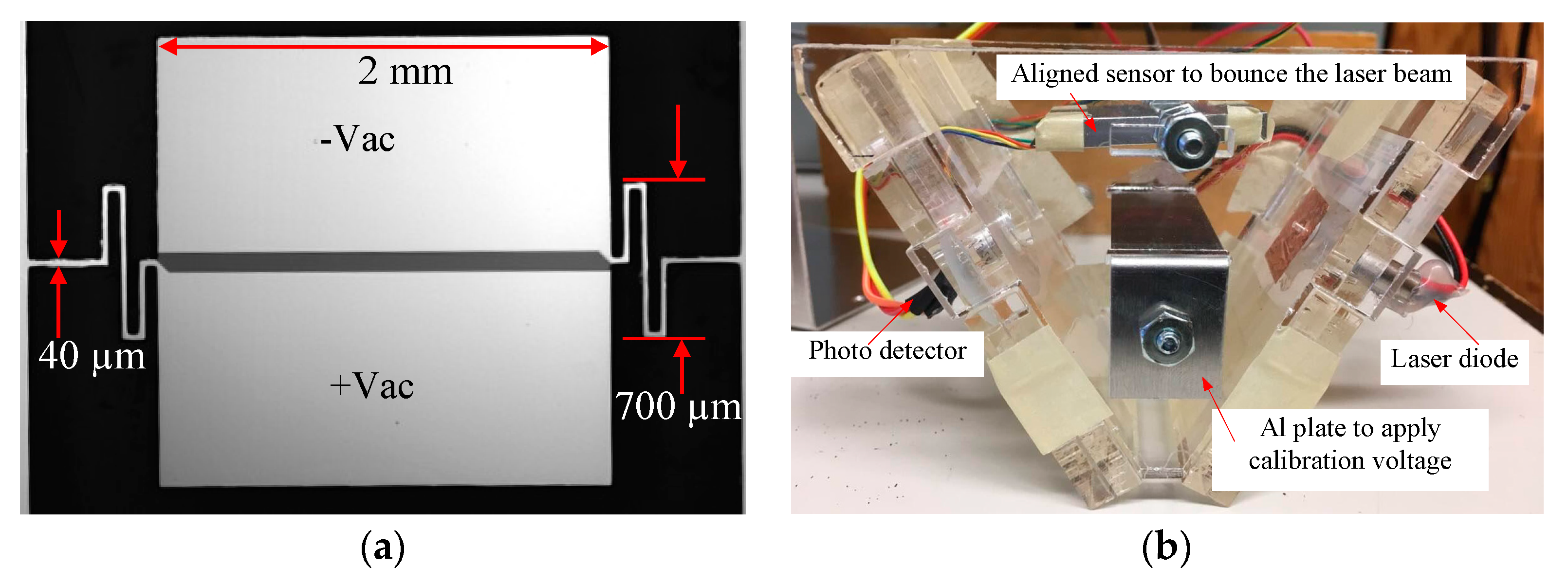
This paper presents a torsional rotating MEMS electric field sensor, that employs differential biased electrodes on the rotating membrane (Figure 1a). This design enables superior sensitivity with significantly reduced bias voltage compared to [4], and operation without reference ground. A laser position measurement system is used to monitor membrane tilt. Figure 1b shows the sensor and laser detection system in a compact acrylic assembly. The sensor membrane and support springs are fabricated from single crystal silicon using a bulk micromachining process, thinning these structures to 14 µm thick. On the front side of the sensor 50 nm of SiO2 is sputtered and finally, 500 nm of Al evaporated for the sensor terminals.
2. Operating Principle
The basic principle is electrostatic force created by an external electric field source pulling on the electrode on the MEMS membrane which is supported by micro springs. This electrostatic force on the membrane is given by Equation (1) [9],
where is permittivity of air, is relative permittivity of the medium, E is the electric field, and A is the electrode area. The two electrodes on the membrane are biased by an 180° out of phase ac voltage. When measuring a dc electric field with an ac bias applied to the membrane electrodes, the force on each electrode can be expressed as Equation (2),
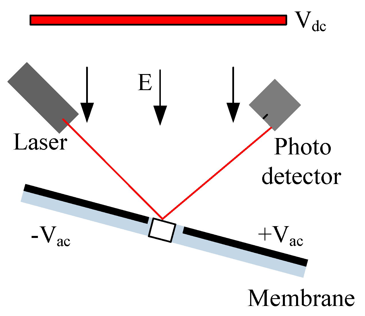
where is the electrode bias voltage and is the distance to dc voltage source . The second term on the right of the equation is the modulated electric field. This can be monitored by the sensor electronics. Control of the amplitude of Vac enables adjustment of sensor sensitivity. Applying an out of phase voltage on electrodes create a differential force on the membrane. The resulting tilting can be measured with high sensitivity as shown in Figure 2.
3. Sensor Fabrication
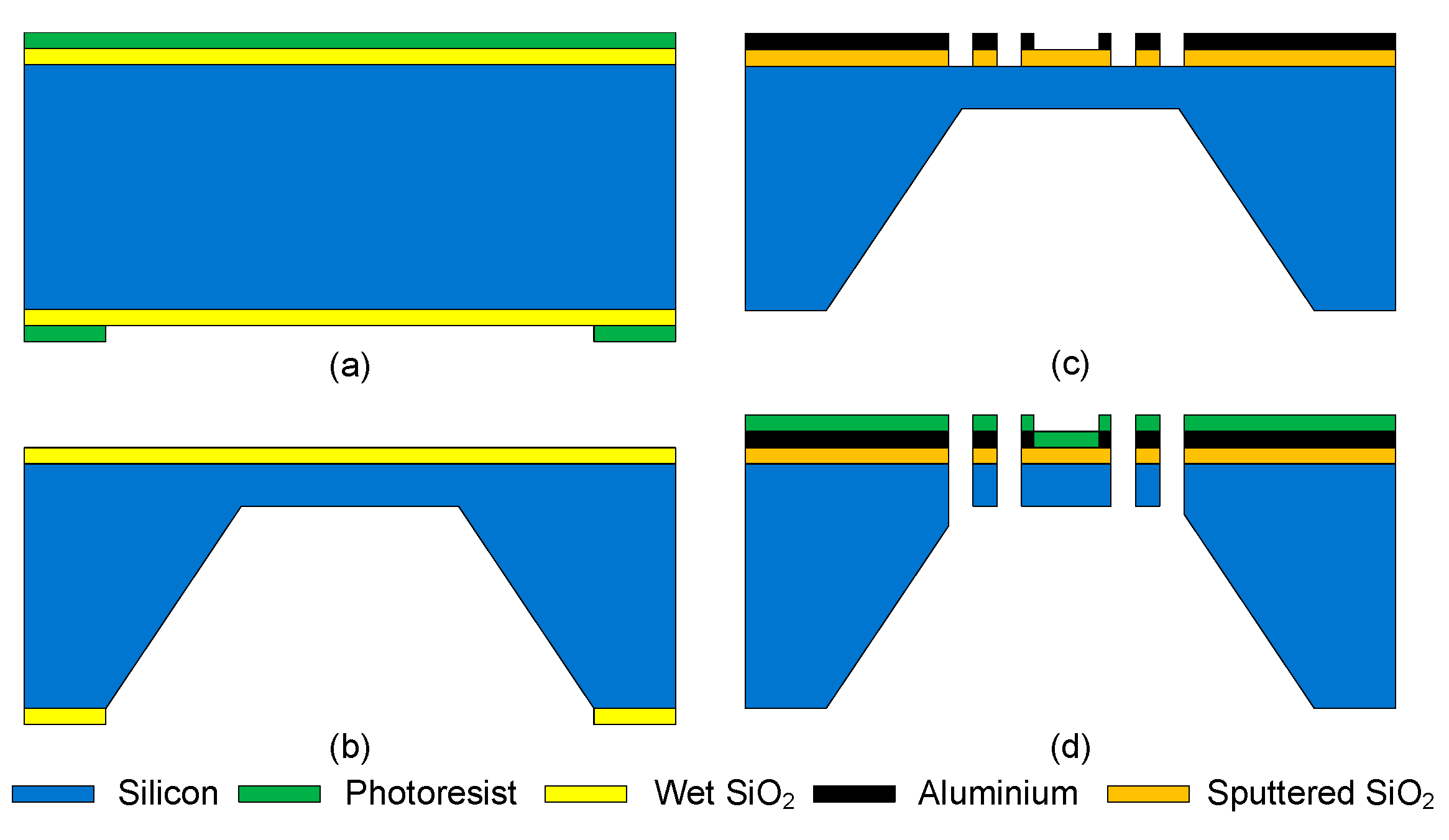
Figure 3 shows main fabrication steps of the torsional sensor. A 250 µm thick silicon wafer used as the substrate. A 1.4 µm thick SiO2 layer was deposited using the wet oxidation process at 1100 °C. This acts as the mask during the KOH back etch process. Figure 3a shows the photoresist patterned on backside of the wafer. Then, SiO2 was removed in the sensor location using 10:1 buffered HF etchant (BOE), and Figure 3b shows thinned substrate to 25 µm using 30% KOH at 80 °C. After backside etch, SiO2 was completely removed using BOE and 50 nm of SiO2 was sputtered on the front of the wafer to act as an insulation layer. Aluminum metal then evaporated, and patterned for sensors electrodes and conduction wires as shown in Figure 3c. Finally, the sensor element and springs were released using plasma etch of the Si, followed by thinning of the silicon to 14 µm from the backside. Figure 3d shows released device with photoresist on frontside. The final step was to remove photoresist using O2 plasma etch.
4. Results
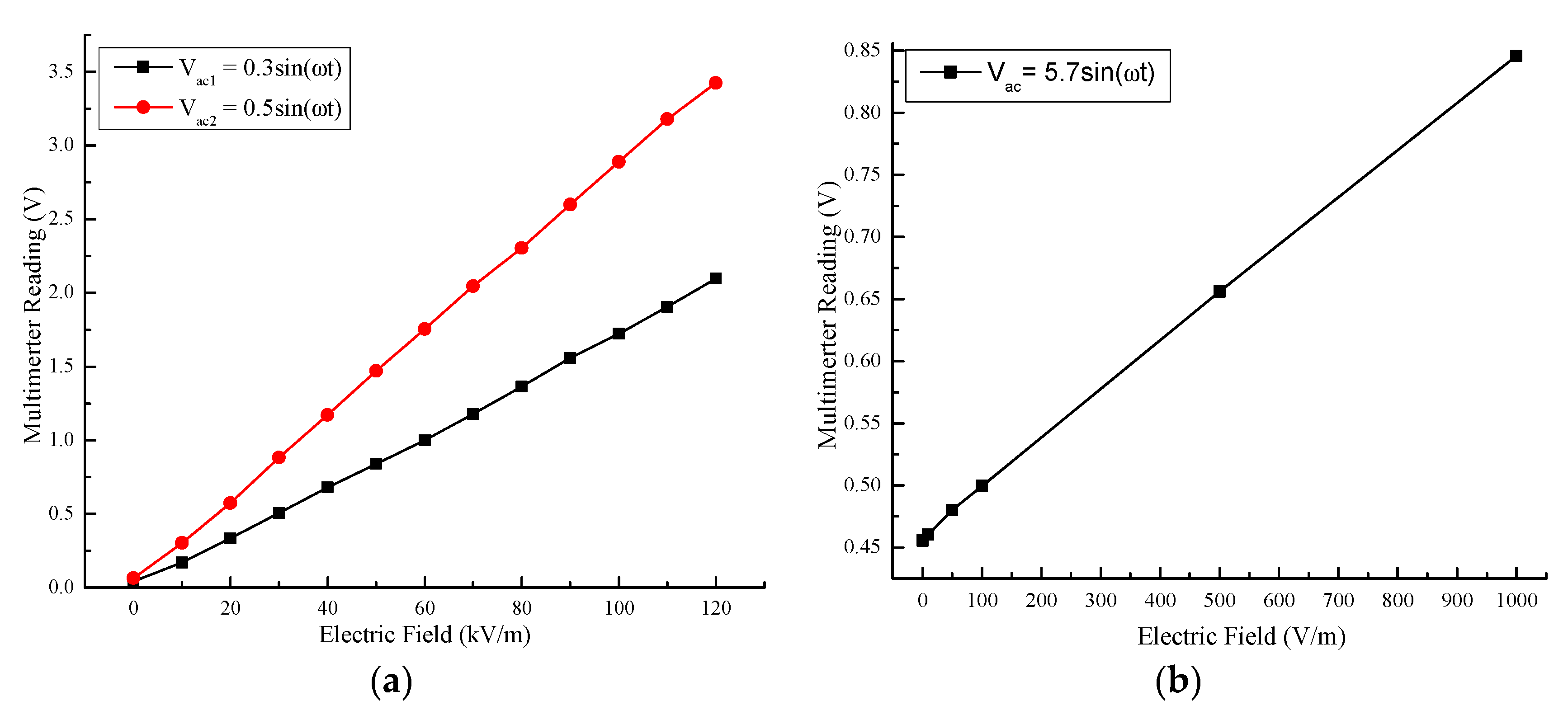
Figure 4 shows the sensor output vs. incident electric fields from 0 to 120 kV/m. We can see that output is linear and that sensitivity is proportional to electrode bias. It should be mentioned that the non-zero result for zero incident dc field is due to a secondary dc electric field originating from the grounded sensor mount.
4. Conclusions
This paper introduces a new type of MEMS electric field sensor based on electrostatic force sensing. Compared to previous works, this sensor demonstrates low operating voltage, higher measurement range and no need for ground reference. When operating at mechanical resonance, it has demonstrated a noise limited resolution of 3 V/m, and measurement up to 120 kV/m.
Acknowledgments
This research was funded by the Natural Sciences and Engineering Research Council (NSERC) of Canada, and Manitoba Hydro (Winnipeg, Canada).
Conflicts of Interest
The authors declare no conflict of interest. The founding sponsors had no role in the design of the study; in the collection, analyses, or interpretation of data; in the writing of the manuscript, and in the decision to publish the results.
References
- Miller, C.J. The measurement of electric fields in live line working. IEEE Trans. 1967, 4, 493–498. [Google Scholar] [CrossRef]
- Razavipour, S.S.; Jahangiri, M.; Sadeghipoor, H. Electrical Field around the overhead Transmission Lines. Proc. World Acad. Sci. Eng. Technol. 2012, 62, 568–571. [Google Scholar]
- Chubb, J.; Harbour, J. A system for the advance warning of risk of lightning. In Proceedings of the Electrostatics Society America, June 2000; pp. 154–157. [Google Scholar]
- Hazards of Electricity and Static Electricity, 6th ed.; Institution of Chemical Engineers: Rugby, UK, 2006; pp. 8–29.
- Wijeweera, G.; Bahreyni, B.; Shafai, C.; Rajapakse, A.; Swatek, D.R. Micromachined Electric Field Sensor to Measure ac and dc Fields in Power Systems. IEEE Trans. Power Deliv. 2009, 24, 988–995. [Google Scholar] [CrossRef]
- Horenstein, M.N.; Stone, P.R. A micro-aperture electrostatic field mill based on MEMS technology. J. Electrostat. 2001, 51, 515–521. [Google Scholar] [CrossRef]
- Yang, P.; Peng, C.; Zhang, H.; Liu, S.; Fang, D.; Xia, S. A high sensitivity SOI electric-field sensor with novel comb-shaped microelectrodes. In Proceedings of the 16th International Solid-State Sensors, Beijing, China, 5–9 June 2011; pp. 1034–1037. [Google Scholar]
- Chen, T.; Shafai, C.; Rajapakse, A.; Liyanage, J.S.H.; Neusitzer, T.D. Micromachined ac/dc electric field sensor with modulated sensitivity. Sens. Actuators A 2016, 245, 76–84. [Google Scholar] [CrossRef]
- Lee, K.B. Principles of Microelectro Mechanical Systems; John Wiley: New York, NY, USA, 2011; pp. 513–519. [Google Scholar]
Figure 1.
(a) Picture of the sensor membrane; (b) Compact acrylic frame holding sensor membrane and laser positon measurement system.
Figure 1.
(a) Picture of the sensor membrane; (b) Compact acrylic frame holding sensor membrane and laser positon measurement system.

Figure 2.
Sensor working principle. The opposite ac bias voltage on the two sides of the membrane, results in differential force across the membrane surface, causing tilting of the membrane.
Figure 2.
Sensor working principle. The opposite ac bias voltage on the two sides of the membrane, results in differential force across the membrane surface, causing tilting of the membrane.

Figure 3.
Sensor fabrication process.

Figure 4.
Sensor response shown for electric fields from 0–120 kV/m, and for different ac bias voltages at sensor resonance of 597 Hz. (a) Measurement of incident dc electric fields over >1 kV/m, taken for two ac bias voltages; (b) Measurement of dc electric fields below <1 kV/m.
Figure 4.
Sensor response shown for electric fields from 0–120 kV/m, and for different ac bias voltages at sensor resonance of 597 Hz. (a) Measurement of incident dc electric fields over >1 kV/m, taken for two ac bias voltages; (b) Measurement of dc electric fields below <1 kV/m.

Publisher’s Note: MDPI stays neutral with regard to jurisdictional claims in published maps and institutional affiliations. |
© 2017 by the authors. Licensee MDPI, Basel, Switzerland. This article is an open access article distributed under the terms and conditions of the Creative Commons Attribution (CC BY) license (https://creativecommons.org/licenses/by/4.0/).
Share and Cite
MDPI and ACS Style
Liyanage, S.; Shafai, C.; Chen, T.; Rajapakse, A. Torsional Moving Electric Field Sensor with Modulated Sensitivity and without Reference Ground. Proceedings 2017, 1, 350. https://doi.org/10.3390/proceedings1040350
AMA Style
Liyanage S, Shafai C, Chen T, Rajapakse A. Torsional Moving Electric Field Sensor with Modulated Sensitivity and without Reference Ground. Proceedings. 2017; 1(4):350. https://doi.org/10.3390/proceedings1040350
Chicago/Turabian StyleLiyanage, Sampath, Cyrus Shafai, Tao Chen, and Athula Rajapakse. 2017. "Torsional Moving Electric Field Sensor with Modulated Sensitivity and without Reference Ground" Proceedings 1, no. 4: 350. https://doi.org/10.3390/proceedings1040350