Analysis on Chattering Phenomena by the Tilt of the Proof Mass in MEMS Switch †


1
Agency for Defense Development, Yuseong, P.O. Box 35, Daejeon 34186, Korea
2
Department of Electrical and Computer Engineering, Seoul National University 301-1116 (#007), 1 Gwanak-ro, Gwanak-gu, Seoul 151-600, Korea
*
Author to whom correspondence should be addressed.
†
Presented at the Eurosensors 2017 Conference, Paris, France, 3–6 September 2017.
Proceedings 2017, 1(4), 349; https://doi.org/10.3390/proceedings1040349
Published: 29 August 2017
(This article belongs to the Proceedings of Proceedings of Eurosensors 2017, Paris, France, 3–6 September 2017)
Abstract
:This paper reports an analysis on the relationship between the tilt of the proof mass in MEMS switch and the chattering phenomena. Low-g MEMS acceleration switch developed by Kim’s group was modelled in 2D and displacements of each end of the proof mass were analysed using RK 4th method. Some elementary assumptions were made to ease the modelling and analysis. The chattering time of the MEMS switch gets longer as the tilt of the proof mass increases. The reason is that the elongated travel distance of one end of proof mass increases the impact velocity and lengthens the bouncing back time. From the results, we found that the chattering phenomena can last very long even if the tilt of the proof mass is very small.
1. Introduction
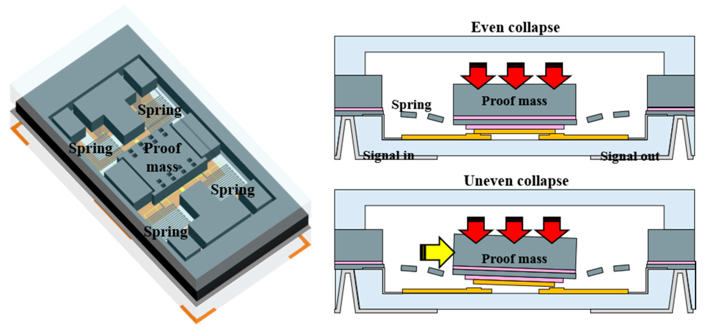
MEMS (micro electromechanical systems) devices are currently studied to be applied in missile systems due to their extremely small size and low power consumption [1,2,3,4]. MEMS acceleration switch turns on at the threshold acceleration, thus it can work as the ignition safety condition for the AFDs (Arm Fire Device) in the missile systems [3]. The cold launch missiles which the main motor ignites after ejection, and the multi-stage rocket motors can prevent unexpected ignition if they use the acceleration signal as a safety condition. The proof mass of low-g MEMS acceleration switch developed by Kim’s group (Figure 1) [5] moves in the z-direction to minimize the installation error.
However, when using a MEMS acceleration switch in missiles, noise forces would act in the off-axis directions. These off-axis forces tilt the posture of the proof mass and destabilize the operation of the switch. As far as we know, the relation between the tilt of the proof mass and chattering was never been explored before. Thus, we need a proper interpretation to expect how long the chattering would last due to the tilt of the proof mass.
2. Analysis Methods
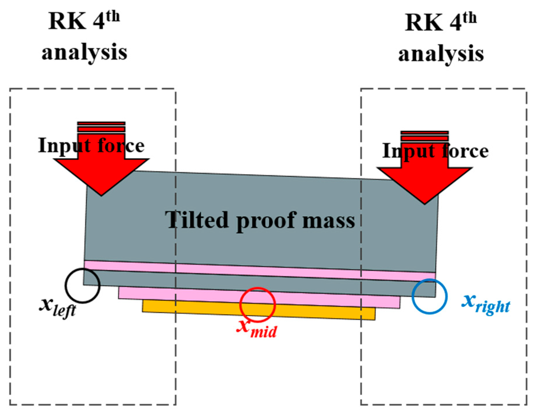
For analysis, we set up the situation where the proof mass is tilted due to the arbitrary off-axis force and moves down at the tilted posture. To ease the analysis, three assumptions were made as follows. (1) The tilt of the proof mass does not affect the spring constant and damping coefficient. (2) Bouncing of one end of the proof mass hardly disturb the movement of the other. (3) The proof mass is not deformed during contact. The low-g MEMS acceleration switch was modelled in 2D as shown in Figure 2. The chattering phenomena was checked by the movements of two end points of the proof mass (, ), which were numerically acquired using Runge-Kutta 4th order method (Equation (1)) [6].
3. Results
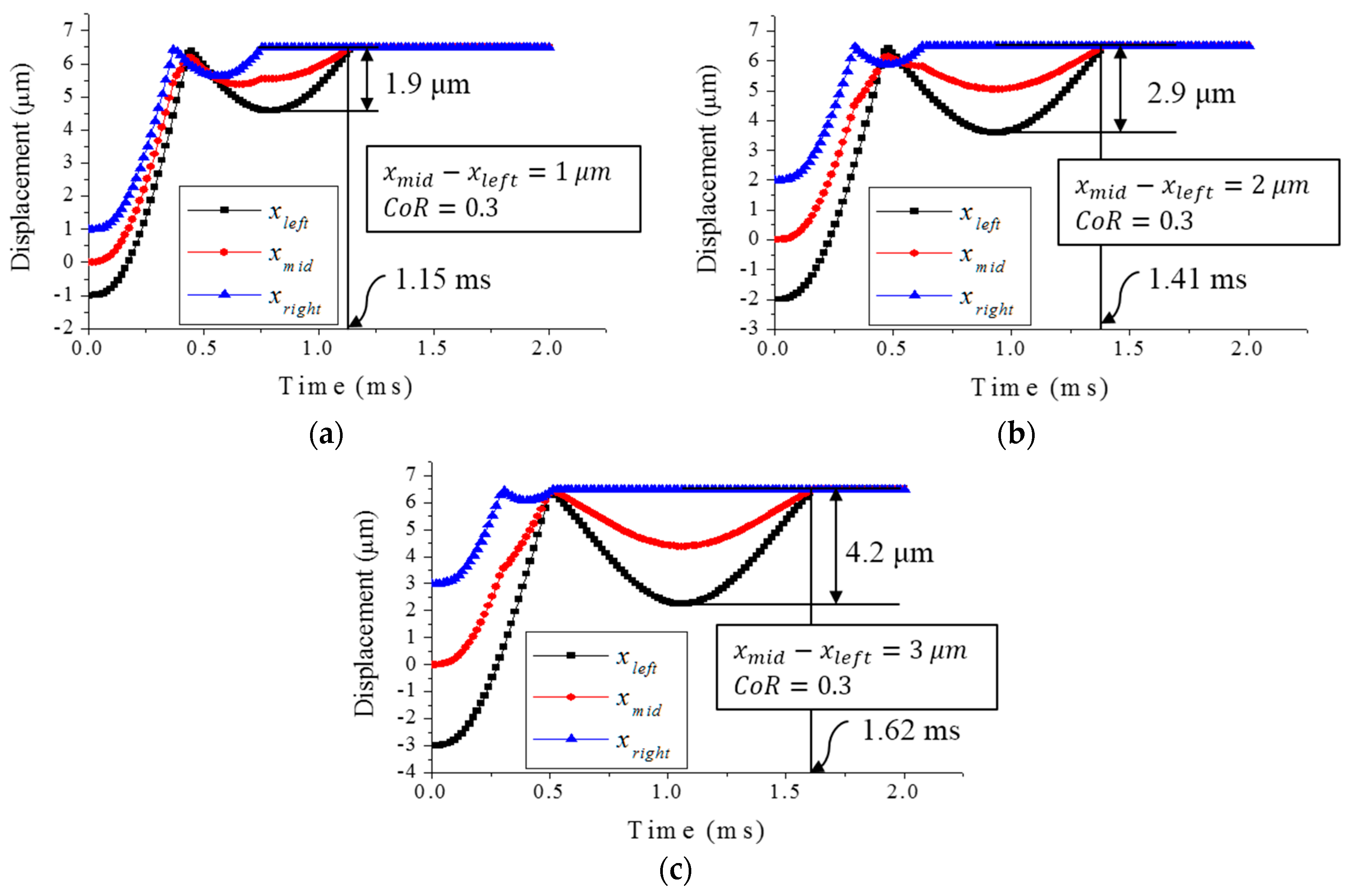
The chattering displacements depending on time for different tilted degrees of the proof mass was calculated in Figure 3. The tilted degree of proof mass is from the difference of vertical heights between the center () and ends (, ) of the proof mass. Three different vertical heights of 1 μm, 2 μm, and 3 μm were analysed. In Figure 3, the vertical heights are (a) 1 μm, (b) 2 μm, and (c) 3 μm, respectively. When the vertical height increases from 1 μm to 3 μm, the bouncing distance increases from 1.9 μm to 4.2 μm and the bouncing back time increases from 1.15 ms to 1.62 ms. In this analysis, the larger the vertical heights difference between the center () and ends (, ) of the proof mass has the longer bouncing distance and bouncing back time.
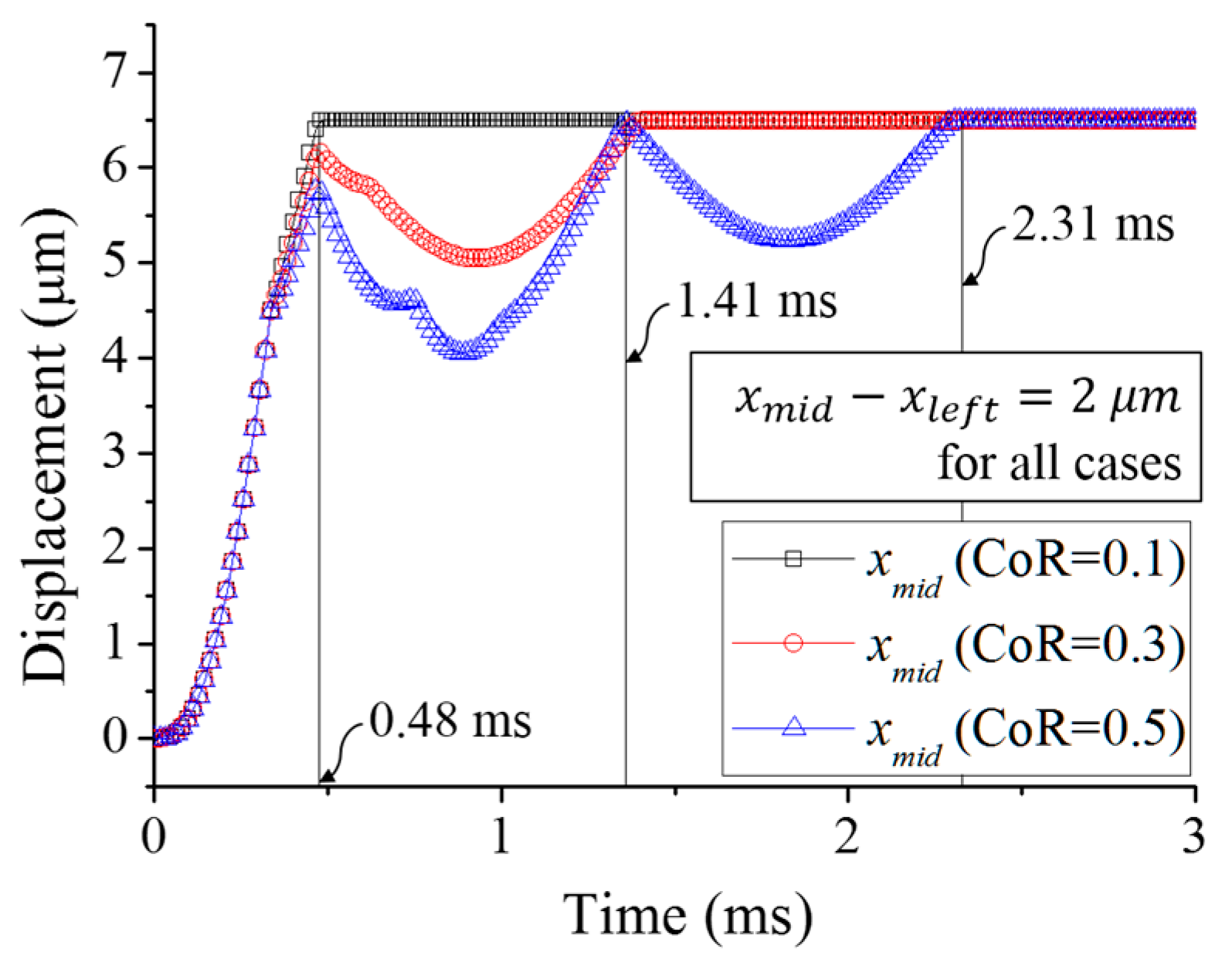
We also analysed the chattering phenomena for the change of the coefficients of restitution (CoR). Figure 4 shows the displacement of depending on time for three different CoRs: 0.1, 0.2 and 0.3.
In the case that the CoR is 0.1, the proof mass showed no bouncing due to not enough impact velocity. In the case that the CoRs are 0.3 and 0.5, the first bouncing back times of two different CoRs are same as 1.41 ms. However, when the CoR is 0.5, the proof mass makes another bouncing back. Of course, the bouncing back time gradually decreases as the number of bouncing adds. In this analysis, we can conclude that the CoR doesn’t affect the bouncing back time but affect the number of bouncing.
4. Discussion
The more the proof mass is tilted, the longer chattering (both time and distance) continues. This is because the upper-tilted end of proof mass gains more velocity before the impact (i.e., contact) and takes more time and more distance to bounce back when the proof mass is tilted more. As the coefficient of restitution increases, the bouncing back distance also increases due to higher impact velocity. However, the increase of the CoR does not affect the bouncing back time but affect the number of bouncing back. From the results, the bouncing back velocity of the proof mass can be the main factor which decides the chattering phenomena. To reduce the chattering phenomena, it is important to reduce the impact velocity of the proof mass. Thus, to minimize the chattering phenomena, we can install an elastic structure below the edges of the proof mass to lower the impact of the proof mass at the contact, thus the bouncing back velocity.
5. Conclusions
We studied the chattering phenomena by the tilt of the proof mass of MEMS acceleration switch using numerical analysis. As the tilt of the proof mass becomes large, the chattering time and chattering distance also increases. The coefficient of restitution (CoR) also affects the chattering distance but it does not affect the bouncing back time. The chattering phenomena highly depends on the impact velocity of the proof mass and installing an elastic structure below the edges of the proof mass will help to minimize the chattering phenomena.
Conflicts of Interest
No conflict of interest. The founding sponsors had no role in the design of the study; in the collection, analyses, or interpretation of data; in the writing of the manuscript, and in the decision to publish the results.
References
- Barbour, N.M. Inertial Navigation Sensors DTIC Document. Available online: http://oai.dtic.mil/oai/oai?verb=getRecord&metadataPrefix=html&identifier=ADA422180 (accessed on 7 August 2017).
- Froyum, K.; Goepfert, S.; Henrickson, J.; Thorland, J. Honeywell micro electro mechanical systems (MEMS) inertial measurement unit (IMU). In Proceedings of the 2012 IEEE/ION Position Location and Navigation Symposium (PLANS), Myrtle Beach, SC, USA, 23–26 April 2012; pp. 831–836. [Google Scholar]
- Nie, W.-R.; Xi, Z.-W.; Xue, W.-Q.; Zhou, Z.-J. Study on inertial response performance of a micro electrical switch for fuze. Def. Technol. 2013, 9, 187–192. [Google Scholar] [CrossRef]
- Robinson, C.H.; Wood, R.H.; Gelak, M.R.; Hoang, T.Q.; Smith, G.L. Ultra-miniature Electro-Mechanical Safety and Arming Device. Google Patents US8276515 B1, 28 May 2013. [Google Scholar]
- Hwang, J.; Ryu, D.; Park, C.; Jang, S.-G.; Lee, C.-I.; Kim, Y.-K. Design and Fabrication of Silicon-based MEMS Acceleration Switch Working Lower than 10 g. J. Micromech. Microeng. 2017, 27, 065009. [Google Scholar] [CrossRef]
- William, H.; Saul, A.T.; William, T.V.; Brian, P.F. Numerical Recipes: The Art of Scientific Computing; Cambridge University Press: Cambridge, UK, 1987; pp. 120–122. [Google Scholar]
Figure 1.
Perspective and cross-section schematics of the low-g MEMS acceleration switch developed by Kim’s group [5].
Figure 1.
Perspective and cross-section schematics of the low-g MEMS acceleration switch developed by Kim’s group [5].

Figure 2.
2D model of the proof mass for chattering analysis using RK 4th method.

Figure 3.
Analysed displacement of (black square), (red circle), and (blue triangle). Each graph shows the result of vertical heights difference ( − ) of (a) 1 μm, (b) 2 μm, and (c) 3 μm, respectively.
Figure 3.
Analysed displacement of (black square), (red circle), and (blue triangle). Each graph shows the result of vertical heights difference ( − ) of (a) 1 μm, (b) 2 μm, and (c) 3 μm, respectively.

Figure 4.
Analysed displacements of for different coefficients of restitutions (CoR). Black square, red circle, and blue triangle indicates cases of having CoR of 0.1, 0.3, and 0.5, respectively.
Figure 4.
Analysed displacements of for different coefficients of restitutions (CoR). Black square, red circle, and blue triangle indicates cases of having CoR of 0.1, 0.3, and 0.5, respectively.


Table 1.
Detailed simulation values used in the numerical analysis.
| Proof mass [kg] (w × l × t) [μm3] | 3.07 × 10⁻⁷ (910 × 910 × 200) |
| Spring constant [N/m] | 4.5 |
| Initial gap [μm] | 6.5 |
| Input force [N] | 3.61× 10⁻⁵ |
| Coefficient of Restitution | 0.1/0.3/0.5 |
| Vertical height between center and end of the proof mass ( − ) [μm] | 1/2/3 |
| Tilted angle [°] | 1.14/2.29/3.43 |
Publisher’s Note: MDPI stays neutral with regard to jurisdictional claims in published maps and institutional affiliations. |
© 2017 by the authors. Licensee MDPI, Basel, Switzerland. This article is an open access article distributed under the terms and conditions of the Creative Commons Attribution (CC BY) license (https://creativecommons.org/licenses/by/4.0/).
Share and Cite
MDPI and ACS Style
Hwang, J.-M.; Hwang, J.; Ryu, D.; Jang, S.-G.; Kim, Y.-K. Analysis on Chattering Phenomena by the Tilt of the Proof Mass in MEMS Switch. Proceedings 2017, 1, 349. https://doi.org/10.3390/proceedings1040349
AMA Style
Hwang J-M, Hwang J, Ryu D, Jang S-G, Kim Y-K. Analysis on Chattering Phenomena by the Tilt of the Proof Mass in MEMS Switch. Proceedings. 2017; 1(4):349. https://doi.org/10.3390/proceedings1040349
Chicago/Turabian StyleHwang, Jung-Min, Jeongki Hwang, Daeho Ryu, Seung-Gyo Jang, and Yong-Kweon Kim. 2017. "Analysis on Chattering Phenomena by the Tilt of the Proof Mass in MEMS Switch" Proceedings 1, no. 4: 349. https://doi.org/10.3390/proceedings1040349