Per-Flow Throughput Fairness in Ring Aggregation Network with Multiple Edge Routers


1
neko 9 Laboratories, Tokyo 140-0001, Japan
2
Institute of Industrial Science, The University of Tokyo, Tokyo 153-8505, Japan
*
Author to whom correspondence should be addressed.
Big Data Cogn. Comput. 2018, 2(3), 17; https://doi.org/10.3390/bdcc2030017
Submission received: 11 June 2018
/
Revised: 12 July 2018
/
Accepted: 17 July 2018
/
Published: 18 July 2018
Abstract
:Ring aggregation networks are often employed by network carriers because of their efficiency and high fault tolerance. A fairness scheme is required in ring aggregation to achieve per-flow throughput fairness and bufferbloat avoidance, because frames are forwarded along multiple ring nodes. N Rate N + 1 Color Marking (NRN + 1CM) was proposed to achieve fairness in ring aggregation networks consisting of Layer-2 Switches (SWs). With NRN + 1CM, frames are selectively discarded based on color and the frame-dropping threshold. To avoid the accumulation of a queuing delay, frames are discarded at upstream nodes in advance through the notification process for the frame-dropping threshold. However, in the previous works, NRN + 1CM was assumed to be employed in a logical daisy chain topology linked to one Edge Router (ER). The currently available threshold notification process of NRN + 1CM cannot be employed for ring networks with multiple ERs. Therefore, this paper proposes a method for applying NRN + 1CM to a ring aggregation network with multiple ERs. With the proposed algorithm, an SW dynamically selects the dropping threshold to send in order to avoid excess frame discarding. The performance of the proposed scheme was confirmed through computer simulations.
1. Introduction
In current networks, bufferbloat is a prevalent problem [1]. The presence of bufferbloat in 3G/4G cellular networks was confirmed in [2]. Bufferbloat refers to the phenomenon of excess buffering of frames and the high latency and low throughput caused by it [3]. This is an increasingly common problem, because the reduced cost and high capacity of memory are leading to more buffers loaded in network equipment. The impact of buffer sizing on Internet services was examined in [4] in view of Quality of Experience (QoE) to show that bufferbloat seriously degrades QoE if buffers are oversized and sustainably filled. The interaction between buffering and various TCP congestion-control schemes in cellular networks was also investigated in [5]. For low extra delay background transport (LEDBAT) [6], a monitoring method for upstream queuing delay was proposed to detect bufferbloat [7].
In carrier networks, a ring aggregation shown in Figure 1, is an efficient and widely-used topology for forwarding traffic from widely-distributed user nodes to a core network. A Layer-2 ring with Ethernet Ring Protection (ERP) [8] is a popular topology for carrier networks [9]. A ring topology consists of Layer-2 Switches (SWs), and Edge Routers (ERs) are connected to the SWs. This network easily suffers from bufferbloat, however, because user traffic is forwarded along multiple ring nodes. If numerous user nodes are connected to SWs, the aggregated traffic to an ER can become congested. The queuing delay increases while throughput decreases in accordance with the number of SWs that the flow traverses. Thus, a fairness scheme is required in ring aggregation to achieve per-flow throughput fairness and bufferbloat avoidance, because frames are forwarded along multiple SWs.
To overcome bufferbloat, the Active Queue Management (AQM) approach has been reconsidered to control the queuing delay, such as Controlled Delay (CoDel) [10]. A Proportional Integral controller-Enhanced (PIE) scheduler [11] was also proposed to control the average queuing latency. The goal of these AQM schemes is overcoming bufferbloat; not per-flow fairness. To achieve per-flow fairness, Fair Queue CoDel (FQ CoDel) is developed as CoDel with Fair Queueing (FQ) [12]. With FQ CoDel, incoming traffic is divided into flows, and each flow is put in a separate queue. However, the deployment of per-flow queuing in high-speed networks is complex and costly.
The resource allocation problems have been intensely studied for various networks. In [13], the problem of joint utility-based customized price and power control in multi-service wireless networks was investigated using S-modular theory. The authors of [14] made suboptimal solutions according to iterative methods for a resource allocation problem with partial fairness considering weighted sum throughput maximization in an orthogonal frequency-division multiple access system. For joint users’ uplink transmission power and data rate allocation in multi-service two-tier femtocell networks, a distributed and iterative algorithm for computing the desired Nash Equilibrium was introduced [15]. In [16], a user association method to maximize the downlink system throughput in a cellular network was proposed. To achieve per-flow fairness and bufferbloat avoidance in ring aggregation networks, N Rate N + 1 Color Marking (NRN + 1CM) was proposed [17,18,19]. Colors are assigned to frames based on input rate, and frames are discarded according to their color and a frame-dropping threshold, which is shared by SWs through a notification process. The performance of NRN + 1CM was confirmed through mathematical formulation and computer simulations; per-flow fairness can be achieved regardless of traffic types, the number of SWs and buffer sizes. However, previous works focused on a logical daisy chain topology with a single ER. The currently available threshold notification process of NRN + 1CM cannot be employed for ring networks with multiple ERs.
Therefore, this paper proposes a method for applying NRN + 1CM to a ring aggregation network with multiple ERs. We also show the resilience of fairness after a link failure. The rest of the paper is organized as follows. Section 2 describes the overview of NRN + 1CM and the problems with existing algorithms. Section 3 describes the proposed algorithm. In Section 4, we evaluate the effect of the proposed algorithm with computer simulations. We provide our conclusion in Section 5.
2. NRN + 1CM
2.1. Overview
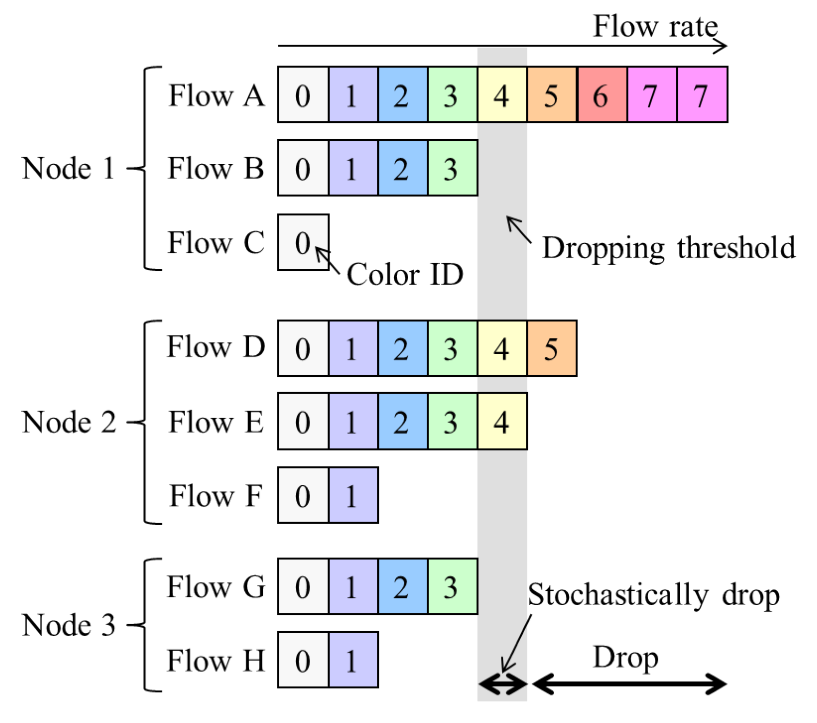
Here, NRN + 1CM is briefly described in order to introduce the proposed algorithm in the next section. It was proposed in [17] to realize per-flow fairness in ring aggregation networks. It is assumed that all the traffic to and from user nodes is transmitted via the core network and that there is no direct communication between user nodes , which is a common situation for IoT applications. The concept for NRN + 1CM is outlined in Figure 2, and the architecture of an SW to employ it is shown in Figure 3. Flows forwarded from another SW are called transit flows, and other flows are called station flows. Express class traffic is transmitted first by Priority Queuing (PQ). The transit Best Effort (BE) frames are directly forwarded to a dropper, and the station BE frames are forwarded to per-station flow markers. They are marked with a color that indicates its dropping priority. Colors are assigned according to the input rate. More colors are used for high-rate flows. For example, eight colors are available in Figure 2. After the color marking, they are sent to the dropper. At the dropper, frames are selectively discarded on the basis of a dropping threshold and the frame color. Undropped frames are enqueued in a BE queue. The dropping threshold is shared with the SWs. Consequently, per-flow throughput fairness is achieved. Details for the marking, frame drop and threshold notification are described in the following subsections.
2.2. Marking
A per user marker marks a BE frame with a color. Let s denote a flow identifier. A marker updates a marking threshold () with a token bucket. Let denote the number of tokens and B denote the bucket length. Let and denote the number of reset tokens. Initially, and . increases at a token-accumulation rate w. If , then is decremented, and is set at . When a frame of length L arrives, is used by . If , then is incremented, and is set at .
After a marker receives a frame and updates , the initial marking value is generated. The probability of () is calculated as follows:
Then, is translated to the marking color n with:
where () is a parameter. The generated color n is marked for the incoming frame. Since increases in accordance with the flow input rate, more colors are used for high rate flows. Let denote the input rate of frames colored with n for one flow. If n is fixed, is constant for all flows.
2.3. Frame Drop
The colored frames are forwarded to the dropper. It decides whether to transmit or discard frames based on their color. Let integer M () denote the dropping threshold and P () denote the dropping probability. The frame is discarded if . Accordingly, the number of discarded colors increases in proportion to M. If the frame belongs to station flows, frames with are discarded with a probability P, and they are transmitted with a probability . Since M increases in accordance with the current queue length, which is described in detail in Section 2.4, the number of discarded colors increases as the congestion becomes heavy. After this process, frames that have not been discarded are forwarded from the SW.
2.4. Threshold Notification
SWs perform a cyclical frame-dropping threshold-notification process. Let m denote a local threshold, p denote a local probability, denote a notified threshold and denote a notified probability.
First, m and p are calculated locally based on the current queue length q and the capacity of the queuing system Q. Here, m is calculated as follows:
where is a positive integer. Moreover, is defined as . If in (3), is satisfied. With , p is calculated as follows:
Second, is updated with and through the notification process. After this update process, is sent to the upstream SW. The update procedure is as follows. Let denote the length of the cycle interval. The most downstream SW sends to an upstream SW with a notification message at every . When this upstream SW receives the message, the dropper is notified of . Then, the dropper updates by comparing and as follows:
For the most downstream SW, is employed, because and are always zero. By repeating this process, the thresholds are propagated to all SWs in the network, and of all ring SWs is updated.
In a ring aggregation network, station flows join transit flows at each SW, and they are forwarded to an edge SW. When an SW does not receive station flow, the SW simply transmits transit flows. The number of flows and the number of enqueued frames are greater at downstream SWs receiving station flows. The most downstream SW receiving station flows is defined as the most congested SW. Therefore, M and P for the most congested SW are shared and used by every SW after the threshold-notification process.
2.5. Problems with NRN + 1CM
However, the system configuration employed in the study so far (Figure 3) focuses on a logical bus topology in which an ER is connected to the most downstream of the cascaded SWs. In particular, in carrier networks that are required to provide high reliability, a ring aggregation topology with multiple ERs (Figure 1) is widely employed. The existing NRN + 1CM cannot be employed in such networks because it does not assume multiple ERs and switching paths. It is important to enable NRN + 1CM to realize fairness in ring aggregation networks with multiple ERs.
The problems that exist with multiple ERs are as follows. Traffic from users is transmitted to any ER via the SWs in the ring. User traffic joins and branches at the SWs, because traffic bound for different ERs coexists in the same link. Moreover, traffic from ERs to users joins and branches at the SWs. The congestion state differs at each link. If each SW simply employs the dropping threshold received from another SW in such situations, the discarding of too many frames leads to the underutilization of links.
As an example, we assume that in Figure 1, the SW1-SW2 link is blocked, and at SW7, two colors () are transmitted to ER0 and three colors () to SW0. SW6 receives the dropping thresholds of both paths from SW7. If SW6 employs a large value as in Section 2.4, only two colors () of frames are transmitted to SW7. All frames whose color satisfies are discarded. The accumulation of the queueing delay is suppressed, but the frames to SW0 are over discarded and the links underutilized.
With ERP, paths are switched on link failures. After the failed link has been blocked, the Ring Protection Link (RPL) is unblocked, and the ring recovers in 50 ms. The transmission routes of the traffic change on the switching paths. Traffic control has to be deployed again based on the new topology.
3. Proposed Algorithm
3.1. Concept
We propose a method for applying NRN + 1CM to a ring aggregation network with multiple ERs. With the proposed algorithm, to avoid discarding too many frames, an SW dynamically selects the dropping threshold to send. If frames from the adjacent SW are transmitted to multiple ports at the SW, the SW selects the dropping threshold of the less congested port and notifies the adjacent SW of the selected value. Frames are not over discarded when we use the dropping threshold of the less congested port. If frames from the adjacent SW are transmitted to a single port at the SW, the SW selects the dropping threshold of the most congested port, because in this case, frames cannot be over discarded.
We describe this with the same example shown in Figure 1. At SW7, two colors () are transmitted to ER0 and three colors () are transmitted to SW0. SW7 selects the dropping threshold of the port linked to SW0, because it is the less congested port. SW6 receives the dropping thresholds of the port to SW0 from SW7. Three colors () of frames are transmitted to SW7. Frames whose color satisfies are discarded at SW6.
With the proposed algorithm, the accumulation of the queueing delay is suppressed, and there is no underutilization of links because frames are not over discarded. The selected threshold notification is described in detail in Section 3.3. On link failures, each queue discards all frames and initializes the dropping threshold and the dropping probability. The SWs equalize the bandwidth again in the new topology.
3.2. Node Architecture
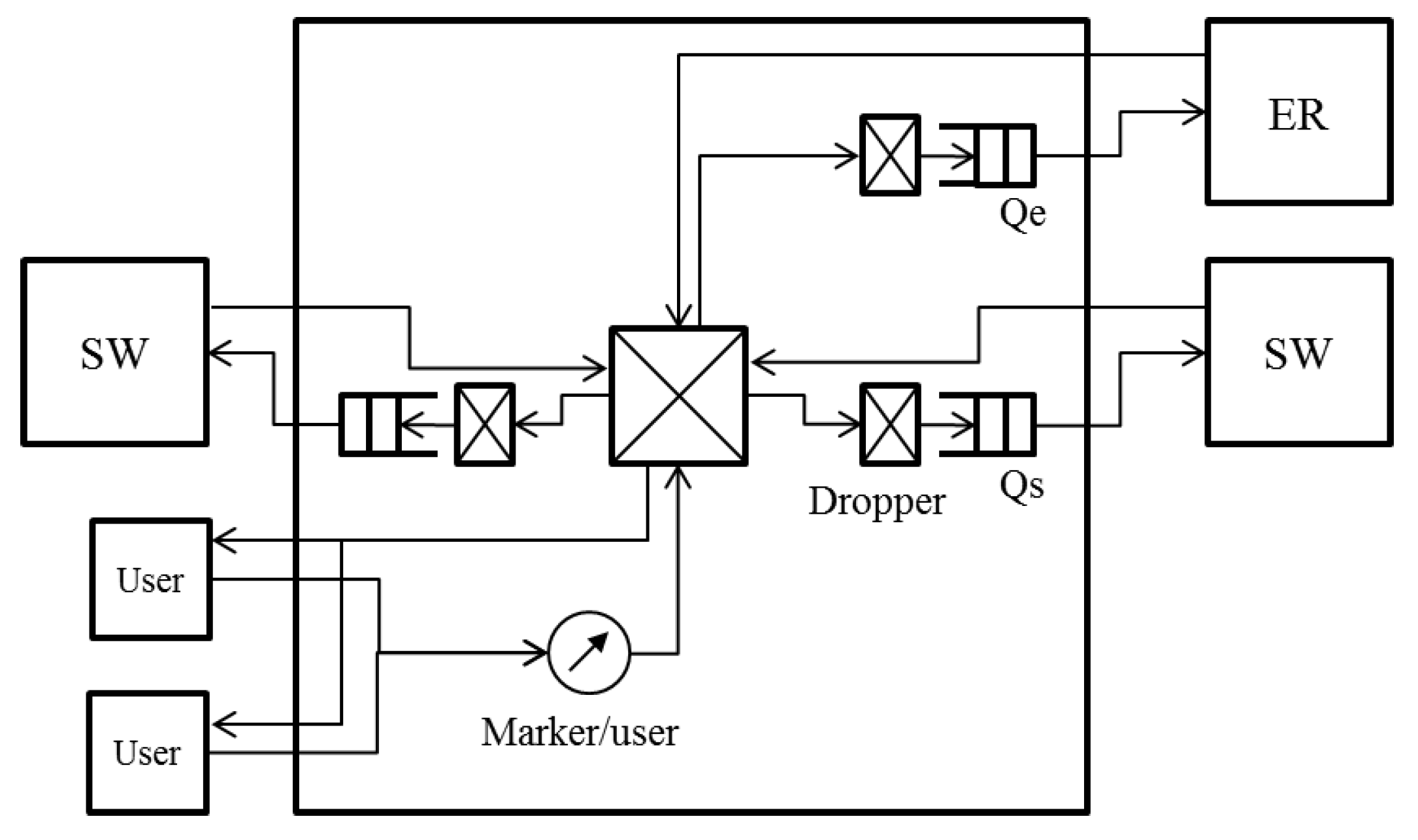
The node architecture for operating the proposed algorithm is shown in Figure 4. Figure 4 shows an SW that is connected to an ER and whose links to adjacent SWs are not blocked. At an SW that is not connected to an ER, the queue to the ER is not used. When either of the links to adjacent SWs is blocked, the link does not transmit any data frame. Only BE queues are shown in Figure 4. The SW has a queue to the ER and queues to adjacent SWs , . Each queue uses a dropper. The frames coming from users are marked with colors by the per user marker. The frames arriving from the ER are assumed to be marked with colors in the same way. The marked frames are divided and transmitted to the queues based on their destination.
3.3. Selected Threshold Notification
We describe the selected threshold notification in detail focusing on . can be described in the same way with the right side on the left. Let denote the larger value of a and b.
Of all the frames queued into , the accumulation of queueing delay occurs for the frames coming from the left SW in Figure 4. We call this left SW in Figure 4 the opposite SW, because it is connected to the reverse port of the ring from . The frames transmitted from the opposite SW are queued into or or are transmitted to the users based on their destination node. and can be congested.
The droppers of and calculate the dropping threshold and the dropping probability with the queue length. Let and denote the calculated values. The values received from the right SW in Figure 4 are described as . When deciding whether or not to discard frames, always uses , and uses .
The SW has flags and for the selected threshold notification. and are the flags for the frame division of each output port. If a frame from the opposite SW is transmitted into , is set at . If it is transmitted into , is set at . The dropping threshold and the dropping probability are sent to the opposite SW cyclically. The interval of the cycle is . If and are both , is selected. Otherwise, is selected. After the notification, all flags are set at . If the port is blocked, the notification process is not performed.
With this algorithm, if frames from the opposite SW are transmitted to multiple ports, the SW selects the dropping threshold of the less congested port and notifies the opposite SW of the selected value. Frames are not over discarded when the dropping threshold of the less congested port is used. If frames from the opposite SW are transmitted to a single port, the SW selects the dropping threshold of the most congested port, because in this case, frames cannot be over discarded. The accumulation of the queueing delay is suppressed, and the underutilization of links does not occur because frames are not over discarded.
4. Evaluation
In this section, we describe our evaluation of the proposed algorithm by computer simulations. The proposed algorithm was integrated with network simulator ns-2 [20].
4.1. Verification
First, we verified the effect of the selected threshold notification on throughput fairness under a simple condition. The proposed algorithm was compared with existing NRN + 1CM. Existing NRN + 1CM employs non-selective threshold notification. With the non-selective threshold notification, SWs always employ and notify the largest threshold.
4.1.1. Assumptions
The simulation conditions were as follows. The network topology is shown in Figure 1. There were eight SWs in the ring. Two ERs were connected to the ring. The SW3-SW4 link was blocked using ERP. All links were 1 Gbps, and the link delay was 0 ms. One hundred fifty users were linked to each SW. They sent 10-Mbps Constant Bit Rate (CBR) UDP flows for 5 s. Sixty of them sent flows to ER0, and 90 of them sent flows to ER1. The number of flows to ER0 and ER1 were not the same for differentiating the congestion state. The parameters were set at , maximum queue length MB, token bucket length KB, initial token , and token accumulation rate Mbps, . The frame length was KB. was 10 ms.
4.1.2. Result
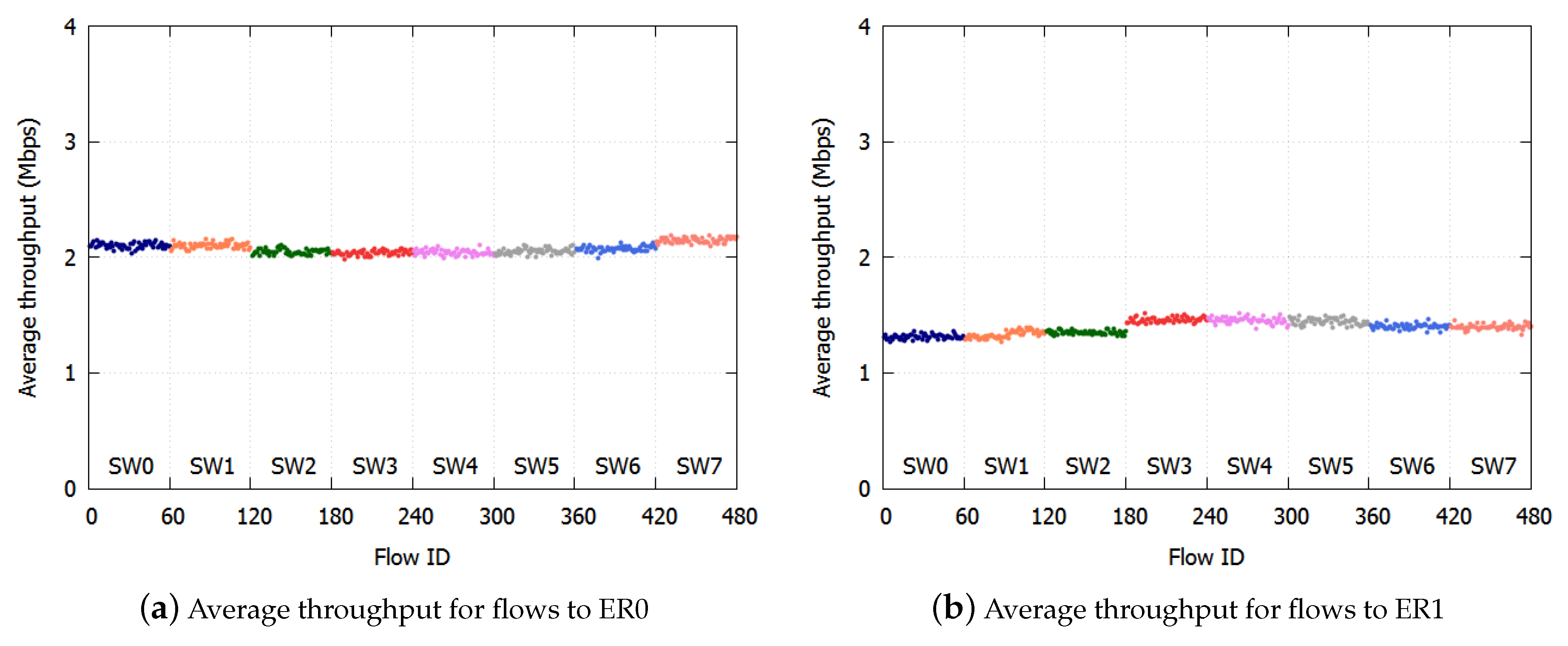
We calculated the average throughput per SW per ER. The results with the proposed algorithm are shown in Figure 5a,b. The results with the existing NRN + 1CM technique are shown in Figure 6a,b. In these figures, we assigned the smallest user IDs to users connected to SW0 and the largest IDs to users connected to SW7.
With the proposed algorithm, the average throughput to ER0 was Mbps, and the standard deviation was Mbps. The average throughput to ER1 was Mbps, and the standard deviation was Mbps. The throughput fairness was realized with high accuracy.
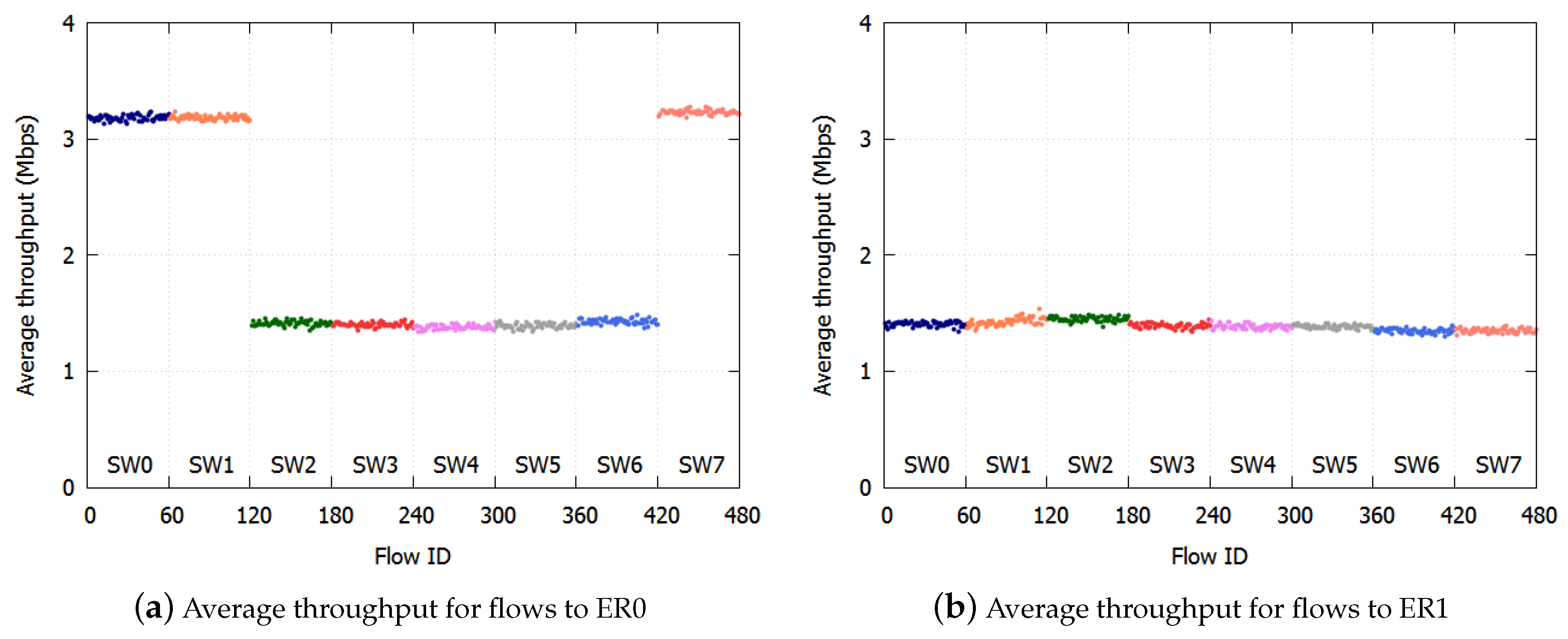
With existing NRN + 1CM, the average throughput was Mbps, and the standard deviation was Mbps to ER0, while the average throughput was Mbps and the standard deviation Mbps to ER1. Unfairness occurred especially with flows destined for ER0. In Figure 6a, the throughputs of the users of SW2-SW6 to ER0 were low.
This is because of the lack of threshold selection for notification. In the simulation condition, the link to ER1 was more congested than the link to ER0. With the existing NRN + 1CM technique, the dropping threshold of the ER1 link was always employed by the SWs because the largest received value was always used by the algorithm when deciding to discard frames. When the frames destined for ER0 and ER1 were transmitted through the same link, the discard decision was performed for all the frames with the dropping threshold of the ER1 link. Therefore, the frames destined for ER0 were over discarded. The throughputs of SW0, SW1 and SW7 were high, because the unoccupied bandwidth caused by discarding too many frames was occupied by these flows. On the other hand, the throughput to ER1 was fair because the link to ER1 was the most congested and there was no over discarding.
In Figure 5b, the throughputs to ER1 were slightly different with the proposed algorithm. This is because only frames coming from outside the ring are discarded with the dropping probability. With the proposed algorithm, the maximum threshold and probability were not shared by all the SWs; therefore, the probability used at the SWs could differ. If an SW used a rather large probability, the throughput of the users connected to the SW decreased. The maximum difference in throughput caused by the difference in the dropping probability was . With the existing NRN + 1CM technique, the maximum values were shared by all SWs, and the throughput of flows to ER1 was fair in Figure 6b.
We confirmed the effect of the proposed algorithm. Fairness was realized with high accuracy for each destination. With the existing NRN + 1CM method, links were underutilized because too many frames were discarded. The underutilization of links is a serious issue as regards the use of network resources. Our proposed algorithm should be employed in the ring aggregation network with multiple ERs.
4.2. Realistic Situation
4.2.1. Assumptions
Second, we confirmed that fairness is realized with the proposed algorithm in more realistic situations.
We assumed there were priority flows, BE heavy user flows and BE TCP flows. The priority flows were assumed to be real-time UDP traffic such as VoIP. The TCP flows were assumed to be Internet traffic. The heavy user flows were assumed to be high rate UDP flows that cause congestion. We evaluated the fairness of the TCP throughput, which is easily affected by congestion, and the recovery of the fairness after a link failure. We compared the proposed algorithm with existing NRN + 1CM and NRN + 1CM without threshold notification.
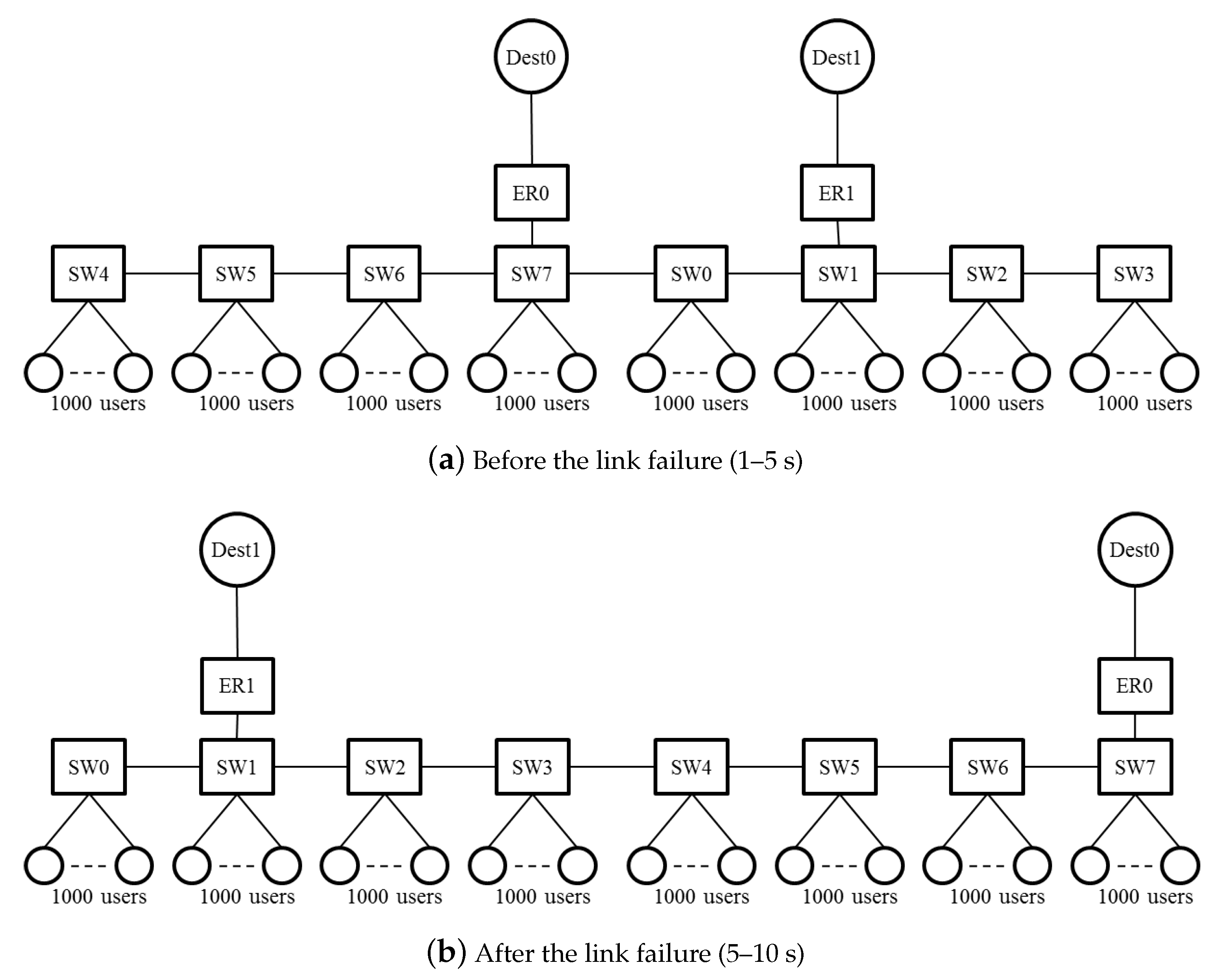
The simulation conditions were as follows. The network topology is shown in Figure 1. There were eight SWs in the ring. Two ERs were connected to the ring. The links between SWs and ERs were 10 Gbps. One thousand users were linked to each SW with a 1-Gbps link. The link delay was 20 ms for ER-Dest0 and ER-Dest1, and ms for other links. The simulation time was 10 ms. At the start of the simulation, the SW3-SW4 link was blocked with ERP. At 5 s, a link failure occurred at SW0-SW7. After the failure, the SW3-SW4 link was unblocked in 50 ms, and the flow transmission was restored. The logical topologies of 1–5 s and 5–10 s are shown in Figure 7a,b.
At 1 s, the users started to send flows. For each SW, 400 users sent TCP flows, and 100 users sent 25-Mbps CBR UDP flows to ER0, while 400 users sent TCP flows and 100 users 25-Mbps CBR UDP flows to ER1. To evaluate the effect of the coexisting traffic on ERs and users, 10-Mbps CBR UDP flows were sent from ER0 to 500 users connected to SW4 and from ER1 to 500 users connected to SW3. As for priority traffic, 500 users of each SW sent 1-Mbps CBR UDP flows to ER1, and ER1 sent 1-Mbps CBR UDP flows to 500 users for each SW. The frame length was KB.
The parameters were set the same as in Section 4.1, except that , MB and Mbps. To improve the marking accuracy of low rate flows, the generated marking value was translated to n with .
4.2.2. Result
We confirmed that the priority flows were transmitted first in all cases.
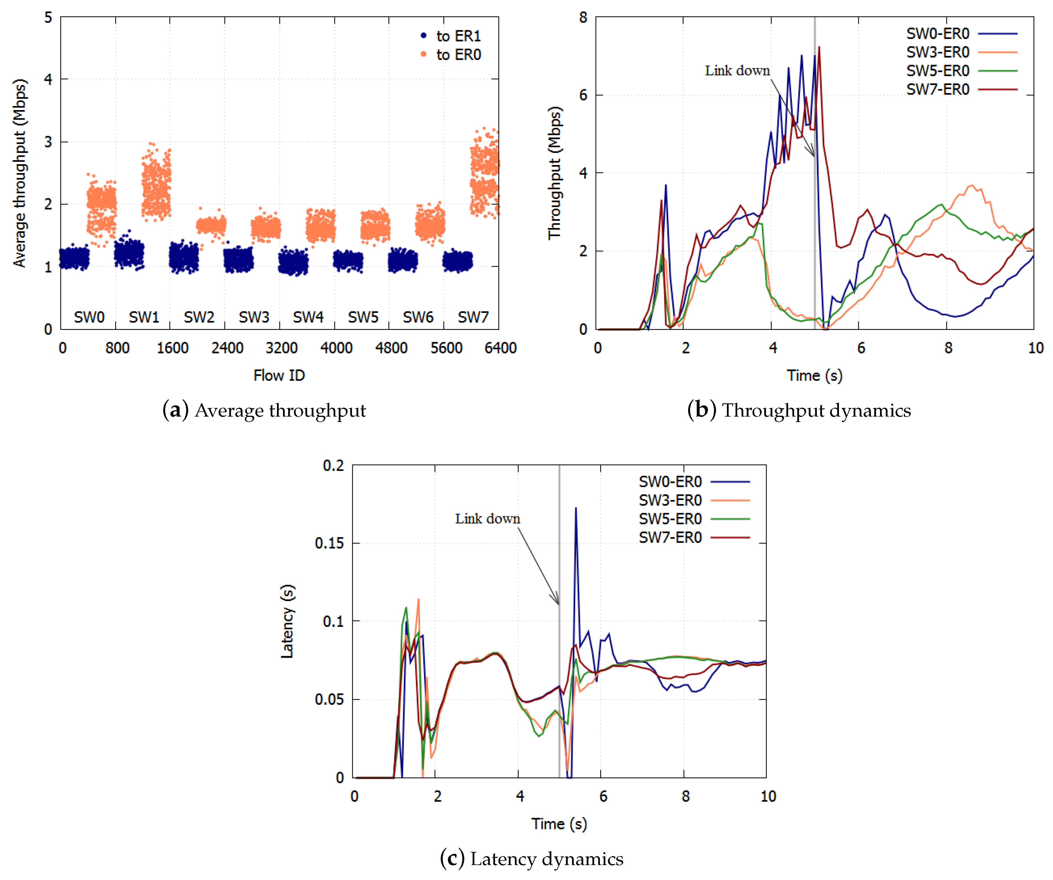
The average throughputs of the TCP flows from 1–10 s with the proposed algorithm are shown in Figure 8a. The average throughput for BE to ER1 was Mbps, and the standard deviation was Mbps. The average to ER0 was Mbps and the standard deviation was Mbps. The bandwidth was equalized with high accuracy. Figure 8b,c show the typical dynamics of the average throughput and the latency of the flows to ER0. The throughput and latency were equalized in about 1 s. The peaks of the TCP throughput differ because the timing of the TCP congestion control caused by the discarding of frames differs. Once a link was down, the throughput and latency were equalized in 1 s.
The results with the existing NRN + 1CM are shown in Figure 9a–c. The average throughput to ER1 was Mbps, and the standard deviation was Mbps. The average throughput to ER0 was Mbps, and the standard deviation was Mbps. Unfairness occurred for the flows to ER0. This is because too many frames were discarded. The SW1-ER1 link was more congested than the SW7-ER0 link. At the SWs that employed the dropping threshold of SW1-ER1, the frames of the flows to ER0 were over discarded. At 1–5 s, the frames of SW2-6 were over discarded. After the link went down, the frames of SW0, in particular, were over discarded.
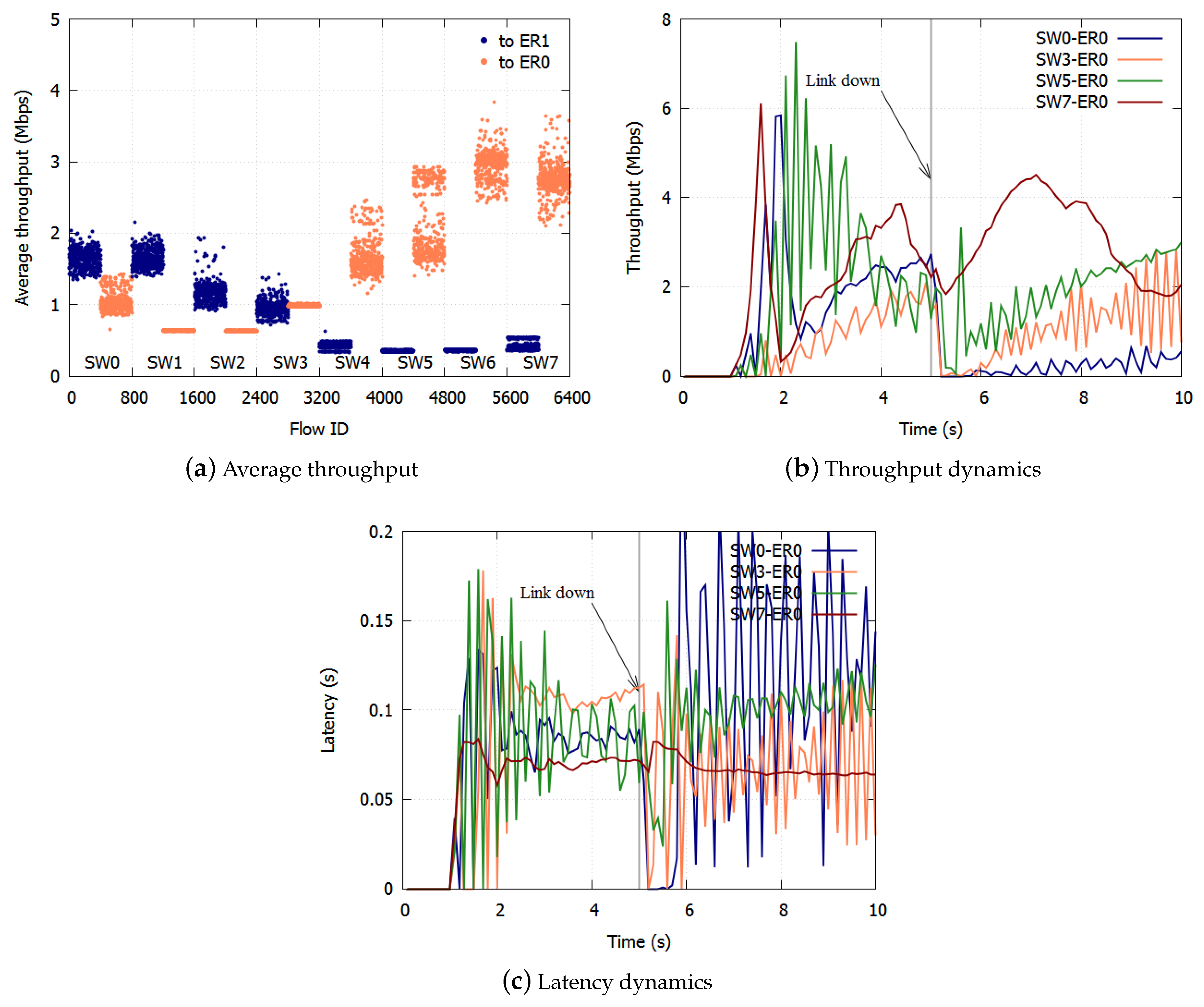
The results with NRN + 1CM without threshold notification are shown in Figure 10a–c. The average throughput to ER1 was Mbps, and the standard deviation was Mbps. The average throughput to ER0 was Mbps, and the standard deviation was Mbps. The average was small, and unfairness occurred. The throughput and latency differed for different SW-ER combinations, before and after the link went down, respectively. This is caused by the accumulation of the queueing delay. The queueing delay accumulates with increases in the number of SWs that flows pass through.
The results indicated the effect of the proposed algorithm in realistic situations. The bandwidth and latency were equalized. Frames were not over discarded. The accumulation of the queueing delay was suppressed by employing selective threshold notification. With the proposed algorithm, fairness was restored after link failures.
5. Conclusions
In this paper, we proposed a method for fair bandwidth sharing with NRN + 1CM in a ring aggregation topology with multiple ERs. To equalize the bandwidths of users with a simple queue configuration, we proposed NRN + 1CM, which is a multicolor marking algorithm. However, the system configuration studied thus far is a logical bus topology in which an ER is connected to the most downstream of the cascaded SWs. In reality, a ring aggregation topology with multiple ERs is widely employed to provide high reliability especially in carrier networks. The existing NRN + 1CM cannot be employed in such networks because it does not assume multiple ERs and switching paths. If each SW simply employs the dropping threshold received from other SW in such situations, the over discarding of frames leads to the underutilization of links.
We proposed a method for applying NRN + 1CM to a ring aggregation network with multiple ERs. With the proposed algorithm, to avoid the over discarding of frames, an SW dynamically selects the dropping threshold to send. If frames from the opposite SW are transmitted to multiple ports at the SW, the SW selects the dropping threshold of the less congested port and notifies the opposite SW of the selected value. Frames are not over discarded by using the dropping threshold of the less congested port. If frames from the opposite SW are transmitted to a single port at the SW, the SW selects the dropping threshold of the most congested port, because in this case frames cannot be over discarded.
With the proposed algorithm, the accumulation of queueing delay is suppressed and there is no underutilization of links because frames are not over discarded. With respect to link failures, each queue discards all frames and initializes the dropping threshold and the dropping probability. The SWs equalize the bandwidth again in the new topology. We confirmed the effect of the proposed algorithm with computer simulations.
The limitation of current NRN + 1CM is that the performance depends on the number of available bits in the frame header. Determining the messaging protocol between SWs used for the notification process will constitute future work.
Author Contributions
Conceptualization, Y.N.; Methodology, Y.N.; Writing, Y.N.; Supervision, K.S.
Funding
This research received no external funding.
Conflicts of Interest
The authors declare no conflict of interest.
References
- Allman, M. Comments on bufferbloat. ACM SIGCOMM Comput. Commun. Rev. 2013, 43, 30–37. [Google Scholar] [CrossRef]
- Jiang, H.; Liu, Z.; Wang, Y.; Lee, K.; Rhee, I. Understanding bufferbloat in cellular networks. In Proceedings of the 2012 ACM SIGCOMM Workshop on Cellular Networks: Operations, Challenges, and Future Design, Helsinki, Finland, 13 August 2012; pp. 1–6. [Google Scholar]
- Gettys, J.; Nichols, K. Bufferbloat: Dark buffers in the internet. Commun. ACM 2012, 55, 57–65. [Google Scholar] [CrossRef]
- Hohlfeld, O.; Pujol, E.; Ciucu, F.; Feldmann, A.; Barford, P. BufferBloat: How Relevant? A QoE Perspective on Buffer Sizing; Technical Report; Technische Universität Berlin: Berlin, Germany, 2012. [Google Scholar]
- Alfredsson, S.; Del Giudice, G.; Garcia, J.; Brunstrom, A.; De Cicco, L.; Mascolo, S. Impact of TCP congestion control on bufferbloat in cellular networks. In Proceedings of the 2013 IEEE 14th International Symposium and Workshops on a World of Wireless, Mobile and Multimedia Networks (WoWMoM), Madrid, Spain, 4–7 June 2013; pp. 1–7. [Google Scholar]
- Shalunov, S.; Hazel, G.; Iyengar, J.; Kuehlewind, M. Low extra delay background transport (LEDBAT). IETF Draft 2010. [Google Scholar] [CrossRef]
- Chirichella, C.; Rossi, D.; Testa, C.; Friedman, T.; Pescapé, A. Remotely gauging upstream bufferbloat delays. In Passive and Active Measurement; Springer: New York, NY, USA, 2013; pp. 250–252. [Google Scholar]
- ITU-T Recommendation G.8032/Y.1344. Ethernet Ring Protection Switching; International Telecommunication Union: Geneva, Switzerland, 2008. [Google Scholar]
- Ryoo, J.; Long, H.; Yang, Y.; Holness, M.; Ahmad, Z.; Rhee, J. Ethernet ring protection for carrier ethernet networks. IEEE Commun. Mag. 2008, 46, 136–143. [Google Scholar] [CrossRef]
- Nichols, K.; Jacobson, V. Controlling queue delay. Commun. ACM 2012, 55, 42–50. [Google Scholar] [CrossRef]
- Pan, R.; Natarajan, P.; Piglione, C.; Prabhu, M.S.; Subramanian, V.; Baker, F.; VerSteeg, B. PIE: A lightweight control scheme to address the bufferbloat problem. In Proceedings of the 2013 IEEE 14th International Conference on High Performance Switching and Routing (HPSR), Taipei, Taiwan, 8–11 July 2013; pp. 148–155. [Google Scholar]
- Demers, A.; Keshav, S.; Shenker, S. Analysis and simulation of a fair queueing algorithm. ACM SIGCOMM Comput. Commun. Rev. 1989, 19, 1–12. [Google Scholar] [CrossRef]
- Tsiropoulou, E.E.; Vamvakas, P.; Papavassiliou, S. Joint customized price and power control for energy-efficient multi-service wireless networks via S-modular theory. IEEE Trans. Green Commun. Netw. 2017, 1, 17–28. [Google Scholar] [CrossRef]
- Moghaddam, M.H.; Mohamed-Pour, K.; Andargoli, S.M.H. Weighted sum throughput maximisation for cooperative relay-aided multi-cell orthogonal frequency division multiple access cellular networks considering partial fairness. IET Commun. 2016, 10, 778–789. [Google Scholar] [CrossRef]
- Tsiropoulou, E.E.; Vamvakas, P.; Papavassiliou, S. Supermodular game-based distributed joint uplink power and rate allocation in two-tier femtocell networks. IEEE Trans. Mob. Comput. 2017, 16, 2656–2667. [Google Scholar] [CrossRef]
- Fukunaga, T.; Yuda, Y.; Hoshino, M.; Higuchi, K. Decentralized user association for (p, α)-proportional fair-based system throughput maximization in cellular networks. In Proceedings of the 2015 International Symposium on Wireless Communication Systems (ISWCS), Brussels, Belgium, 25–28 August 2015; pp. 136–140. [Google Scholar]
- Nakayama, Y.; Oota, N. N Rate N+1 Color Marking: Per-Flow Fairness in Ring Aggregation Networks. IEEE Trans. Commun. 2014, 62, 4401–4412. [Google Scholar] [CrossRef]
- Nakayama, Y.; Sezaki, K. Avoiding bufferbloat with frame-drop threshold notification in ring aggregation networks. In Proceedings of the 2015 21st Asia-Pacific Conference on Communications (APCC), Kyoto, Japan, 14–16 October 2015; pp. 508–513. [Google Scholar]
- Nakayama, Y.; Sezaki, K. Bufferbloat Avoidance with Frame-Dropping Threshold Notification in Ring Aggregation Networks. IEICE Trans. Commun. 2017, 100, 313–322. [Google Scholar] [CrossRef]
- Network Simulator ns-2. Available online: http://www.isi.edu/nsnam/ns/ (accessed on 1 July 2016).
Figure 1.
Ring aggregation network; Layer-2 switches (SW) compose a ring, and multiple edge routers are connected to forward traffic from user nodes to core networks.
Figure 1.
Ring aggregation network; Layer-2 switches (SW) compose a ring, and multiple edge routers are connected to forward traffic from user nodes to core networks.
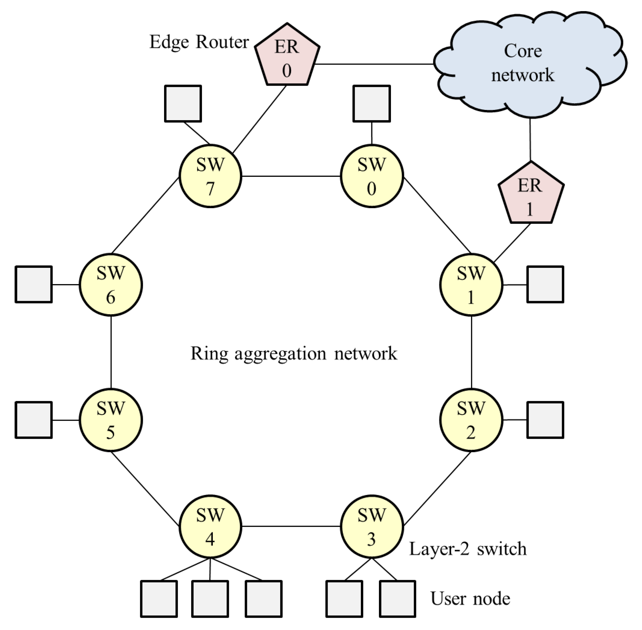
Figure 2.
Concept for N Rate N + 1 Color Marking (NRN + 1CM); colors are assigned to frames according to the flow input rate. Frames are selectively discarded on the basis of a dropping threshold and the frame color.
Figure 2.
Concept for N Rate N + 1 Color Marking (NRN + 1CM); colors are assigned to frames according to the flow input rate. Frames are selectively discarded on the basis of a dropping threshold and the frame color.

Figure 3.
Node architecture for employing existing NRN + 1CM in a ring aggregation network with a single ER.
Figure 3.
Node architecture for employing existing NRN + 1CM in a ring aggregation network with a single ER.
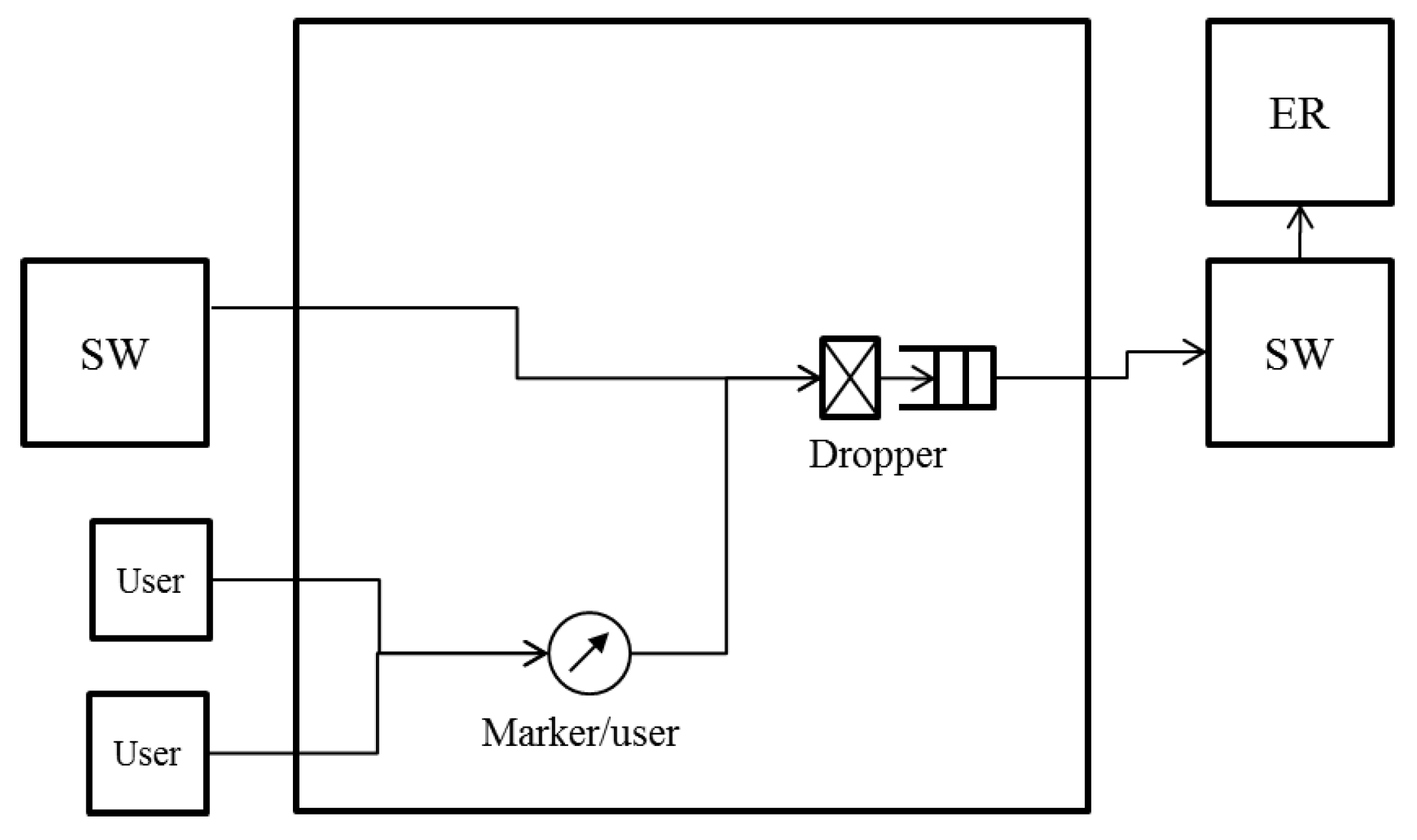
Figure 4.
Node architecture for employing the proposed NRN + 1CM in a ring aggregation network with multiple ERs.
Figure 4.
Node architecture for employing the proposed NRN + 1CM in a ring aggregation network with multiple ERs.

Figure 5.
Simulation results with the proposed algorithm. The throughput fairness was realized with high accuracy.
Figure 5.
Simulation results with the proposed algorithm. The throughput fairness was realized with high accuracy.

Figure 6.
Simulation results with existing NRN + 1CM. The throughput unfairness occurred especially with flows destined for ER0.
Figure 6.
Simulation results with existing NRN + 1CM. The throughput unfairness occurred especially with flows destined for ER0.

Figure 7.
Logical topology of the simulated network. At 5 s, a link failure occurred at SW0-SW7.

Figure 8.
Result with the proposed algorithm.
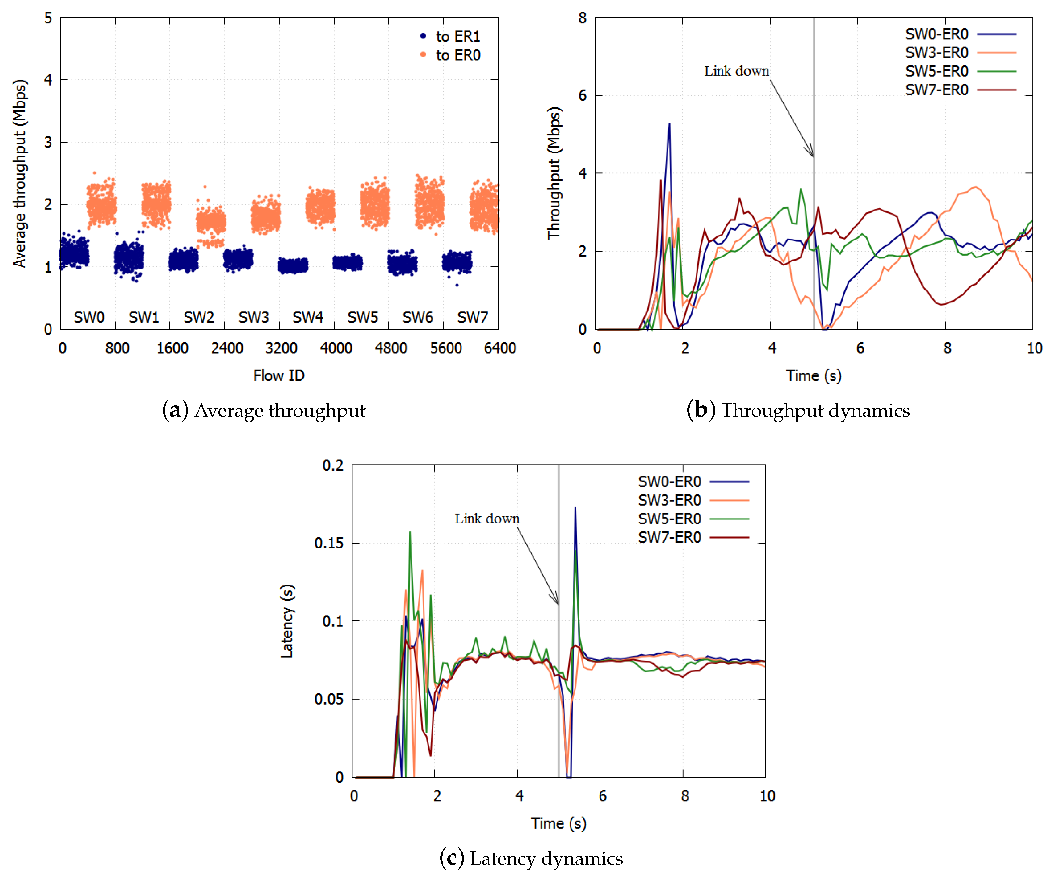
Figure 9.
Result with existing NRN + 1CM.

Figure 10.
Result without notification.
© 2018 by the authors. Licensee MDPI, Basel, Switzerland. This article is an open access article distributed under the terms and conditions of the Creative Commons Attribution (CC BY) license (http://creativecommons.org/licenses/by/4.0/).
Share and Cite
MDPI and ACS Style
Nakayama, Y.; Sezaki, K. Per-Flow Throughput Fairness in Ring Aggregation Network with Multiple Edge Routers. Big Data Cogn. Comput. 2018, 2, 17. https://doi.org/10.3390/bdcc2030017
AMA Style
Nakayama Y, Sezaki K. Per-Flow Throughput Fairness in Ring Aggregation Network with Multiple Edge Routers. Big Data and Cognitive Computing. 2018; 2(3):17. https://doi.org/10.3390/bdcc2030017
Chicago/Turabian StyleNakayama, Yu, and Kaoru Sezaki. 2018. "Per-Flow Throughput Fairness in Ring Aggregation Network with Multiple Edge Routers" Big Data and Cognitive Computing 2, no. 3: 17. https://doi.org/10.3390/bdcc2030017