Aerodynamic Design of Low-Speed Axial-Flow Fans: A Historical Overview


Istituto Nazionale di Fisica Nucleare (INFN), 35131 Padova, Italy
†
Current Address: via Marzolo 8, 35131 Padova, Italy.
Designs 2018, 2(3), 20; https://doi.org/10.3390/designs2030020
Submission received: 8 May 2018
/
Revised: 5 June 2018
/
Accepted: 8 June 2018
/
Published: 21 June 2018
(This article belongs to the Special Issue Challenges and Progress in Turbomachinery Design)
Abstract
:The paper presents a historical overview of the developments of aerodynamic design methods for low-speed axial-flow fans. This historical overview starts from the first fan applications, dating back to the 16th century, and arrives to the modern times of computer-based design techniques, passing through the pioneering times of aerodynamic theories and the times of designing before computers. The overview shows that the major achievements in the axial fan design discipline have actually been related to other technological fields, such as marine and aeronautical propulsion, as well as to the development of wind tunnels. At the end of the paper, the reader will have acquired a complete panorama of how the historical developments of the discipline have brought us to the current state of the art.
1. Introduction
In this paper, a historical overview of barely 200 years of aerodynamic design methods for axial-flow fans is summarized, including also some notes on fan installations of the 16th century, in order to present how the developments of the aerodynamic discipline brought us up to the current state of the art in axial fan technology.
The axial-flow fan is likely the most familiar turbomachine: everyone, at least once in life, has dealt with a table fan and, as a matter of fact, axial fans are widely diffused for several industrial applications. In spite of having been one of the workhorses of modern societies, the axial fan generally received quite a modest consideration: it is generally referred to as the “stepchild of technology” [1] or “the poor relation of turbomachines” [2]. Consequently, unlike airplanes and aero-engines, there are no references that describe how axial fans have evolved during the years according to the developments of aerodynamic knowledge. However, being aware of the history of aerodynamic design methods for these machines is important to understand how the current state of the art was achieved and, furthermore, to avoid repeating something (errors included) that has already been done in the past.
The sources within this overview were collected during five years of research activity on low-speed axial-flow fan design, trying to feed the curiosity of how the methodologies currently adopted had been achieved. The publications considered were of three types: (i) technical books on the subject, (ii) papers on peer-reviewed journals and conference proceedings, and (iii) technical reports from military and civil agencies (as, for instance, NACA and NASA).
In the main part of the text, the developments of the axial fan design discipline are summarized; the design developments that share common features have been grouped for years:
- Pre–20th Century—Axial Fans before the Development of Aerodynamic Theories
- 1890–1930, From Propellers to Fan Theories
- 1937–1953, The Development of Design Theories Specific for Axial Fans
- 1953–1980, Achieving the Maturity of Analytic Design Methods and the Introduction of Computers
- 1987–2010, Analytic Design and CFD Optimization.
- 2011–Current Days, State of the Art and Recent Developments
This is an arbitrary classification, however, and others might be eventually considered. At the end of the paper, a section Methods and Discussion, which describes how the sources have been found is included as well.
The article attempts to sew a thread along almost two centuries of aerodynamic methods to design low-speed axial fans, with the aim of presenting to fan designers and to enthusiasts of the history of technology a structured picture on how the developments of aerodynamic theories has conducted us up to the current state of the art.
2. Fan Design History
2.1. Pre-20th Century: Axial Fans before the Development of Aerodynamic Theories
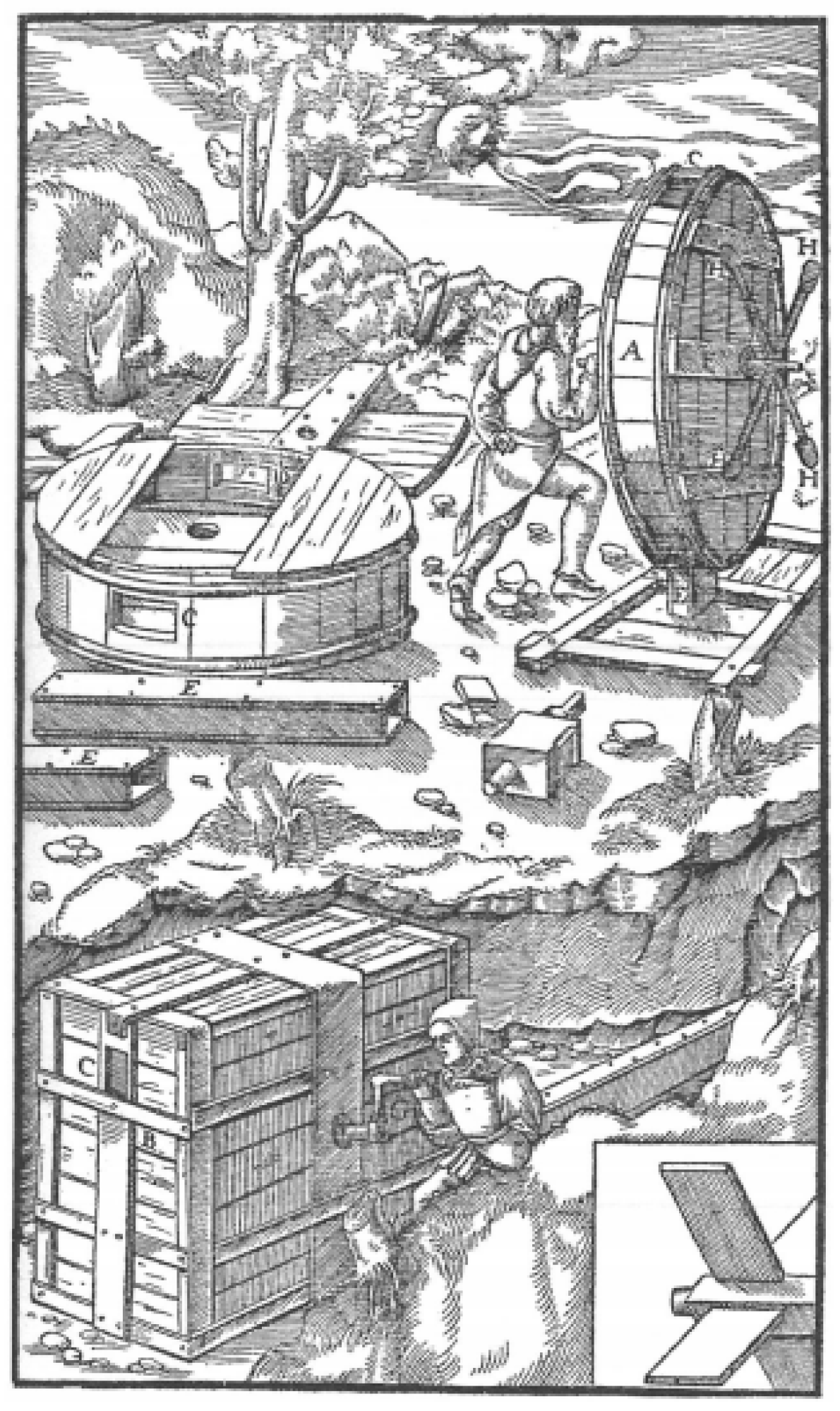
As for the first flying machines, also the first axial fans were operating well before the appearance of reliable theories of aerodynamic lift. The first air-treating machines seem to be related to the mining activity: in 1556, the world had just exited from the Middle Ages when Georgius Agricola wrote the book “De Re Metallica” [3], in which he describes the activities related to metal extraction in German mines. Agricola’s illustrations show systems of mechanical ventilation of the underground tunnels with bellows and fans (a primitive type of centrifugal impeller in that case, see Figure 1).
The limited knowledge within the field of fluid mechanics at those times suggests that these machines were created by the intuition of some brilliant-minded practical men, rather than according to theoretical basis. However, after these pioneering machines, fans went into decline for almost 250 years, substituted into the task of mine ventilation by furnaces and piston pumps [4]. We must take a step forward to 1827 to find documents on the first axial fan in Paisley, Scotland, again for mine ventilation purposes: the machine was composed of a rotor with inclined blades, installed on a vertical shaft and rotating within a circular casing. It is fair to highlight that this machine was operating around seventy years before the appearance of the circulation theories of lift, independently published by Kutta and Joukowsky at the beginning of the 20th century [5]. Nonetheless, it is likely that whoever designed that 1827 machine was aware of the research by Euler on the operation of pumps [6] and windmills [7]. In the middle of the 18th century, the Swiss mathematician derived the turbine equation (Equation (1)), which was named after him, which relates the torque T that can be extracted/provided to the shaft of a rotating machine according to the variation of the velocities through the rotor:
where is the volumetric flow-rate, the mass density, r the radius and the tangential velocities at the entrance (1) and exit (2) of the blade channel.
Euler’s research has probably guided the pioneering designs of the axial machines, but it is expected that the 1827 axial fan had been designed according to an empirical trial and error technique, because of the rather limited knowledge of fluid-dynamics of those times. However, the lack of knowledge of those times on: (i) aerodynamics; and (ii) metallurgy (to run impellers at sufficient speed to achieve suitable pressure differences) quickly discarded axial fans in favor of centrifugal machines [4]. Outside mines and with the electrification of cities (≃1882–1885), the ventilation of crowded environments soon became another main application for fans [4], mostly using propeller-type machines (Figure 2). Such fans were featuring simple metal blades with no twist (see again Figure 2), suggesting a rather crude aerodynamic design.
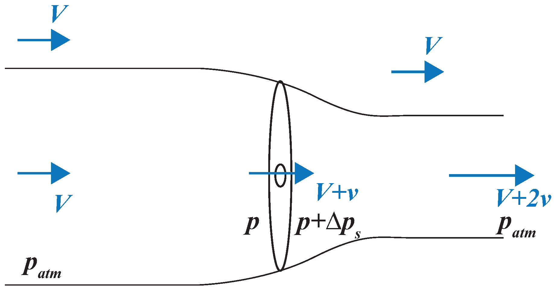
The first aerodynamic theories that could guide the design of axial-flow machines were not related to fans, but rather to marine propellers [9]. In particular, Rankine introduced in 1865 the actuator-disk theory (also named axial momentum theory), which was later developed by Froude in 1889, taking the name of these two authors [9]. Under several simplifying assumptions (see e.g., [10]), this one-dimensional model considers the kinematic behavior of the flow inside a control volume (Figure 3) and provides a rather immediate way of computing the axial thrust on the rotor and the torque T (here reported as developed in [10]):
where is the angular velocity, the air density, while V and v are, respectively, the upstream fluid velocity at the infinite and the incremental velocity at the rotor (equal to half the incremental velocity in the jet, see Figure 3). Clearly, two of the primary design variables are contained in Equation (2): the diameter D and the rotational speed . An important achievement of this theory was related to the comprehension that the velocity of the flow in proximity of a propeller that operates in a free medium (i.e., unducted) is higher than the velocity at the infinite [9], due to the vena-contracta fluid behavior. The same behavior, however, cannot occur on a ducted machine because of the constraint on the axial velocity imposed by the continuity of the fluid medium. According to Glauert (in [9], p. 178), the axial momentum theory provides a sound basis to estimate the ideal efficiency of a propeller for given operational conditions, but cannot provide any information on the rotor shape. Accordingly, the momentum theory cannot be considered an effective design method as, on the contrary, the blade element theory, which is described in the next section.
2.2. 1890–1930, From Propellers to Fan Theories
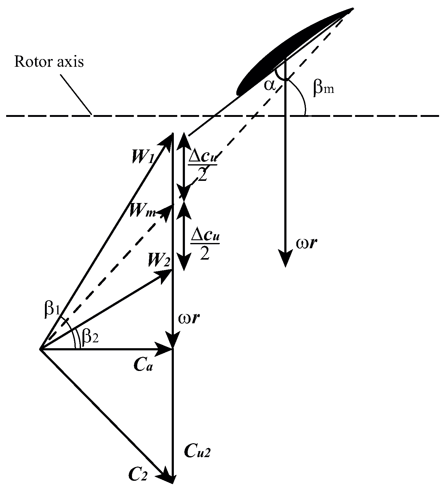
Also during the revolutionary years for aerodynamics between the end of the 19th century and the beginning of the 20th century, discoveries into the design of axial machines were addressed to marine and, later, aerial propellers. Although originally introduced “[…] in a rather crude form” by Froude in 1878 [9], the Blade Element Theory is due mainly to Drzewiecki, who first published an essay about in 1892 [9], again for maritime applications. Drzewiecki’s theory (whose final form was published only in 1920 [9,11]) considers the rotor blade as divided into a large number of small adjacent elements, each one behaving as an airfoil of known characteristics, that interacts with the air flowing with a local relative velocity , identified by the vectorial sum of the motion V (between the fluid at infinite and the propeller) and the rotation of the blade element (which varies according to the radius). It is unknown if Rateau was aware of Drzewiecki’s research when he developed a high-pressure axial fan with a relatively high (≃0.7) hub-to-tip ratio at the end of the 19th century ([4], p. 9); nonetheless, that machine featured inlet guide vanes, indicating a solid understanding of the Euler Equation (1). However, we do know that in 1903 the Wright brothers could not find any reliable aerodynamic theory to guide them into the design of the propellers for their flying machines [12]. The Wrights thus decided to develop their own design method, whose effectiveness and success is now well-known; as a matter of fact, the quality of Wrights’ propellers is suggested as one of the main reasons behind their epic accomplishment [5,12]. Drzewiecki’s design theory featured two main issues: (i) the uncertainty related to the actual airfoil characteristics (in that period, it was still being discussed whether design data should pertain to a wing of finite span or to an infinite one, as is actually the case [9,11]); and (ii) which was the most correct method to compute the relative velocity at the blade. Regarding this last issue, Pistolesi [11] in 1921 wrote that there was a discussion between Drzewiecki, who was for computing the mean velocity as , and those who were supporting the inflow theory, which conversely claims that the velocity should be computed including the increments on the axial and tangential velocities at the rotor. In the same paper [11], starting from a direct analogy with the vortical system of a finite wing, the author describes how these increments are related to the flow field induced by the vortex systems generated by the rotor. For a fan, it can be shown (e.g., [13]) that the computation of the mean velocity shall account for the velocity increments, due to the flow deflection induced by the rotor. As a consequence, a definitive form for the computation of the velocity triangles was achieved (Figure 4). In [11], it is also outlined that some authors, Drzewiecki included, were beginning to approach a cascade method, which accounts also for the reciprocate interference effects of the blades, to analyze the performance of the propellers.
Meanwhile, Betz successfully included the slipstream rotation within the actuator–disk theory, extending the axial momentum theory into the general form [9].
Up to the beginning of the 1920s, these theories were applied to propellers. To the best of the author’s knowledge, the first publication related to the design of a ducted machine is due again to Pistolesi in [14], to study the design of a 3.3 m fan for a new closed loop wind tunnel. In this paper, Pistolesi relates the thrust on the rotor to the pressure rise required to overcome the duct resistance, thus shifting the target from providing thrust to overcoming the pressure losses. Two years later, Glauert [10] was also suggesting the blade element method to design axial fans.
By the beginning of the 1930s, aerodynamic design methods for fans were achieving a more definite form. In 1934, Marks and Weske from Harward were designing and testing a rotor-straightener fan [15]: it is interesting noticing their use of the potential theory to compute the streamlines at the rotor entrance. These authors were also investigating design expedients to reduce fan noise, including inclined leading and trailing edges and an even number of guide vanes with respect to the three rotor blades. Furthermore, the effects related to the distance of the vanes and the rotor were assessed both from the performance and the acoustical point of view. However, the partially empirical approach to the design still denotes some gaps in the theory underneath. The first structured research specifically addressing axial fan design was performed by Keller [16] at the ETH, Zurich, under the supervision of Ackeret. Keller was probably the first author who abandoned the general but rather complex vortex theory, to start directly with using the velocity triangles, whose definitive form had been achieved a few years before. Among the results, Keller presented the form of the fundamental design equation for each blade element of the fan rotor:
where is the lift coefficient of the blade element, l the chord length, z the number of blades, the increase of energy delivered to the air, the mean relative velocity, and n the rotational speed of the rotor (in rpm).
A few years later, the work by Keller was translated by Marks and Weske and published in the book [17], which became the first publication on the subject that achieved a global dissemination. After sharing much with marine and aeronautical propellers, it was finally time also for these industrial machines to achieve their own aerodynamic design method.
2.3. 1937–1953, The Development of Design Theories Specific for Axial Fans
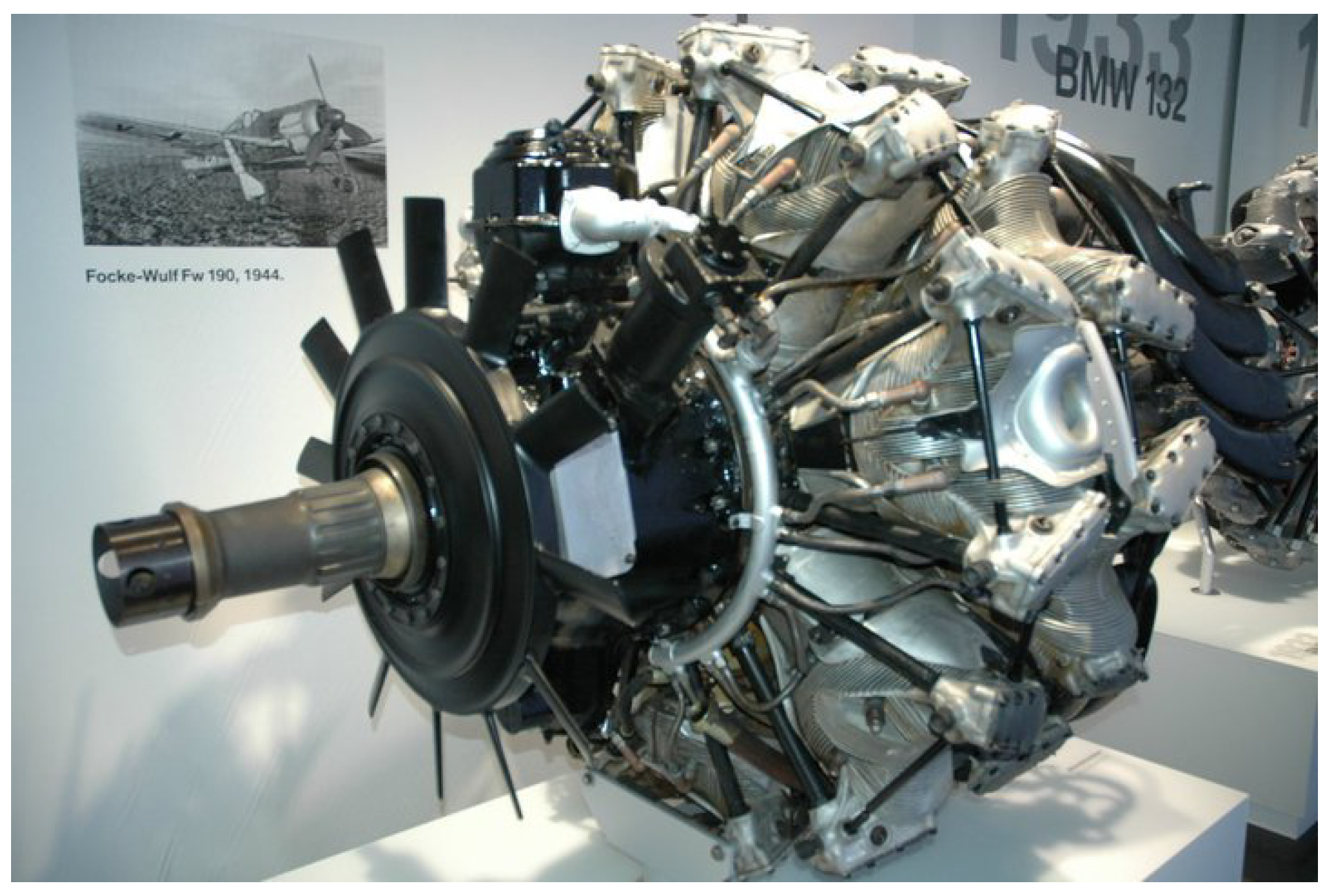
While Keller’s book was being published, the world was preparing for the tragic years of World War II. This was a period of tremendous scientific discoveries and technical developments, with the innovations in the field of fan aerodynamics pertaining to this second case and related, in particular, to military research. In 1937, Ruden [18] conducted an extensive theoretical and experimental investigation on the design of single-stage axial fans for a new wind tunnel in Göttingen; once again, the design developments for these air-treating machines were descending from aeronautical applications. Starting again from the general vortex theory, this investigation was the first work that addressed the possibility of using loading distributions along the blade differing from the free-vortex (i.e., isoenergetic) one. In particular, Ruden reports that at those times it was not explained why rotors with chord lengths that increase from the hub toward the tip show a smoother behavior at throttling with respect to blades with decreasing chords, which show an abrupt stall (See also the recent paper [19]). Ruden’s report is the first reference that included directly the radial equilibrium equation (Equation (4)) into the design process, to compute the meridional distribution of the velocity at the rotor outlet. The author concluded that rotors with blades featuring increasing chord lengths are suitable for higher loadings with respect to the free-vortex designs; furthermore, he tested several rotor–stator prototypes, with the best solution that showed an efficiency close to 90%. A few years later, on the other side of the ocean, the American NACA started to focus on axial-fan design as well. In 1942, several investigations [20,21,22] were performed to address the design of fan cooling systems for aero-engine purposes: in the 1940s, in fact, aeronautical piston engines were installed behind the cowling to reduce the drag of the aircraft [12]. The fan rotors were co-axial with the main engine shaft (see Figure 5) and were featuring quite high hub-to-tip ratios; in particular, NACA reports address geometries.
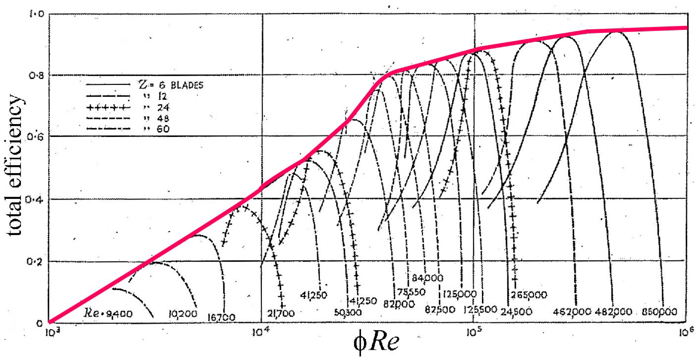
Starting from Keller’s theory, Bell [20] and Bell and Dekoster [21,22] experimentally assessed the effects on fan performance and efficiency of several design aspects, as the configuration (rotor-only or preswirler-rotor), the increase of blade solidity, the use of different airfoil sections and the blade positioning angle. However, the objective of these reports was presenting the achievable performance of the fans rather than looking for a general design method. It is remarkable that Bell [20] claims that the results of the investigation could be extended to the design of axial compressors as well, suggesting that the attention of the research was already addressing these types of machines. As a matter of fact, during those years, axial compressors were sharing many geometrical and operational similarities with axial fans, and consequently several NACA research reports addressed both the applications. This is also the case of the 1943 work by Eckert [23], in which the author assessed the effects of the Reynolds number on the performance and efficiency of several rotors. Eckert suggested that the rotor efficiency depends on the product , with the ratio between the axial velocity through the fan annulus and the tip speed, while can be approximately computed on the blade speed at the tip and with the blade height. The results of Eckert’s experiments showed a monotonous increase of both the performance and the efficiency with increasing (see Figure 6 for the efficiency). In spite of the importance of such indications for fan designers and operators, today’s fan community appears rather forgetful about Eckert’s contribution, although being cited into the works by Koffman [24] and Eck [1].
In 1944, the NACA obtained and translated the work by Ruden [18] and, after the previous experimental investigations, also the American institution extended the research on theoretical methods. In 1947, Kahane [25] studied the pressure rise that can be achieved by different single-stage configurations and concluded that the preswirler-rotor is able to provide higher performance than the rotor-only and the rotor-straightener ones. Furthermore, in the same year, this author developed and applied Ruden’s equations to design two rotors with loading distributions different than the free-vortex one [26]. Consequently to the departure from the free-vortex distribution, the meridional velocity at the rotor exit is not homogeneous (it becomes approximately triangular) and an accurate design method needs to account for this feature to select and stagger the blade elements. The differential equation, generally known as radial equilibrium, that allows for computing the axial velocity at the rotor exit according to a given swirl distribution , is reported as derived from Kahane’s work (under the assumption of no preswirl, i.e., ):
where is the local blade-element efficiency. The computed velocity distribution shall simultaneously respect the continuity equation:
These equations (and the more general ones, including pre-swirl, reported in [18,26]) allow for designing fan blades according to vortex criteria different from the conventional and conceptually simplest free-vortex one. Kahane [26] designed two rotors with constant-swirl () and rigid-body swirl distribution (), respectively: the experimental testing campaign showed an appreciable agreement with the design assumptions and the capability of these geometries to achieve relevant pressure rises. These arbitrary and forced vortex designs (more generally known as Non-Free-Vortex (NFV)) are advantageous to increase the fan pressure-rise in the presence of constraints on the dimensions and on the rotational speed of the machine.
At the beginning of 1950, Koffman [24] provided several indications on the fan design methods, including aspects as the blade surface finish and the detrimental effects consequent to the absence of the nose-cone. Although not introducing much innovation, Koffman’s paper presents an interesting picture of the state of the art on axial fan design at the end of the second World War. In the beginning of the paper, the author claims that its design procedure, based on Keller’s theory, had been successfully applied in the eight years before on several fighting vehicles.
2.4. 1953–1980, Achieving the Maturity of Analytic Design Methods and the Introduction of Computers
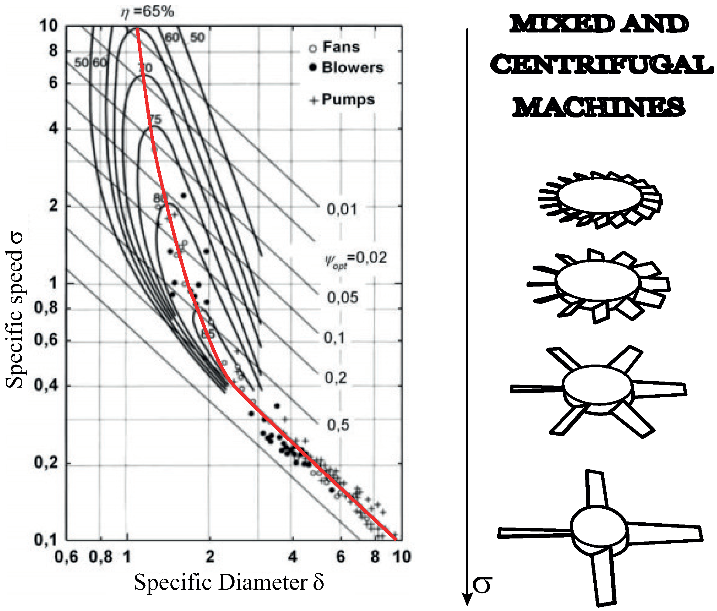
At the beginning of the 1950s, military attention had definitely shifted toward axial compressors, delegating the research on axial fans to industry and to a few academic enthusiasts. In 1953, Cordier [27] presented the diagram that took his name (see Figure 7 Left), collecting the performance of “optimum” fans and pumps in terms of specific speed and diameter (specific speed and diameter are computed as: ; ). The primary function of this well-known diagram is identifying the operational range that pertains to each type of machine (i.e., axial or centrifugal) [28]; nonetheless, several authors used and still use it in the preliminary design phase to select the fan diameter D or the rotational speed n, even if this practice is not encouraged by others (e.g., [29,30]). Regardless of its use, the Cordier diagram represents a milestone in the history of turbomachine design and is still a reference for any low-speed fan and pump designer. The physical explanation underneath the Cordier line (i.e., the line that best interpolates the data of Figure 7) is that, for a given couple of requirements (flow-rate and pressure rise), there is an optimum bijective relation between the machine diameter and the rotor speed; in other words, there is a (mean) velocity triangle that achieves the required operation with higher efficiency with respect to all the others possible. The primary importance of the specific speed parameter in designing axial fan machines was already well understood in 1955 [31], as evidenced in Figure 7 (Right).
The results presented by Cordier in Figure 7 were purely empirical, while Marcinowski [32] in his research on axial fans derived the inclusion of the hub-to-tip ratio inside the same diagram, thus providing a further indication to the designer. Furthermore, the same author addressed the problem of providing an analytic method to compute the optimum hub-to-tip value. Marcinowski investigated the Strscheletzky criterion, which requires a minimum ratio between the meridional velocity and the circumferential velocity in order to avoid a dead wake downstream of the impeller hub: the results are summarized in Equations (6) and (7), which relate the optimum hub-to-tip ratio with the frictionless (theoric- th) design point:
where the flow and pressure coefficients are defined as and , respectively. The optimal hub-to-tip values are different depending on if they refer to the constrained case (C) (e.g., for the Rotor-Straightener configuration) or the axially unconstrained (UC) one (e.g., in case of rotor-only machines). According to Bamberger [33], Marcinowski’s findings are still relevant nowadays; however, likely due to the limited dissemination consequent to the use of the German language for the publication, the international fan community accessed these findings only twenty years later, in the English edition of the book by Eck [1]. According to the author’s best knowledge, Marcinoswki’s approach is still the only analytic method that allows a computation of the hub-to-tip ratio.
In 1952, the famous firm Woods of Colchester financed the publication of the first edition of a handbook on fan engineering [34] that soon became a must in the field of ventilation. The original edition of the book was edited by Osborne and Turner, whose names will appear again later in this paper. Although it might appear strange that a firm shares part of its know-how with the general public, the international success achieved by this publication (reprinted in several editions) surely contributed to the spreading of knowledge and to the development of the discipline. In his book [4], Cory acknowledges the merits of this manufacturer, in particular to the widening of the operational range of axial fans.
During the 1960s and the beginning of the 1970s, three pillars of the fan design literature made their appearance, referring to the names of Wallis [8], Osborne [29], and Eck [1] (whose German first version of the book actually dates back to the 1950s). Thanks to the improvements in the design techniques, during these years, axial fans gained market share compared to centrifugal machines [4,8]. All three of these references provide extensive design methods that rely on solid theoretical basis, each one featuring its strengths: the books by Osborne and Eck, in particular, provide a quite complete view of the fan operation (including indications for centrifugal and mixed machines); furthermore, as reported previously, Eck’s book presented the application of the Strscheletzky criterion investigated by Marcinowski for the computation of the hub-to-tip ratio. On the contrary, Wallis was the first that focused again the attention on fans with blades designed with arbitrary vortex criteria (i.e., blades designed according to non-free-vortex loading distributions); this author also included a design method that was using cascade data, rather than isolated airfoil ones, to design rotors with high solidities in case of demanding pressure-rise applications. Quite surprisingly, all of these authors do not treat exhaustively the design of rotor-only axial fans, although this type of machine represents the most common type of axial-flow fan for industrial applications. With respect to the use of cascade data in the fan design process, Turner in 1966 [35] was suggesting that the cascade approach might substitute definitively isolated airfoil data in the conventional approach. The report, however, concludes with claiming the necessity of an experimental validation and nowadays most of the industrial fans are still designed using data of isolated airfoils from several databases (e.g., [36]). It is of interest to highlight that Turner’s report was justified by a renewed interest in axial fans in England due to the appearance in those years of the hovercrafts.
Meanwhile, at the beginning of the 1960s, several researchers started to address the use of non-radial-stacking (NRS) lines in turbomachinery to stagger the blade elements. In 1963, Smith and Yeh [37] presented an approximate method to account for the effects of sweep and dihedral on the performance of axial-flow turbomachinery blades; in 1971, Lewis and Hill [38] presented a qualitative description of the effects of these geometrical features in turbomachines and included a development of the actuator disk theory to account for swept cascade. The first experimental systematic investigation on axial fans with forward swept blades was presented by Mohammed and Raj [39]: these authors observed an improvement of the performance and efficiency of the NRS fan with respect to the one with radial blades and concluded that including a small amount of sweep (≃5–10) into the design of the blade can be advantageous in several circumstances.
Introducing the research on cascade design by Wallis, in 1968, Oliver [40] prepared a precursor of this paper, presenting a historical summary on the developments of axial flow machines. In his paper, Oliver suggests that the vortex theory, which dominated the first years of the design methods, had been abandoned mainly because of its complexity. Nonetheless, an attempt toward a unified design and analysis method for ducted fans and propellers was then proposed by Borst [41] in 1978: the method is based on the blade element theory and on the vortex theory (to determine three-dimensional effects), and allows the estimation of the stage axial thrust and torque. Borst’s approach showed good agreement against experimental results on a helicopter ducted tail rotor and an axial compressor.
In the second half of the 20th century, the advent of computers revolutionized engineering calculations and the axial fan discipline was not an exception. The first automated method of solving the axial fan design exercise was proposed in 1965 by Myles et al. [42] at the National Engineering Laboratory (NEL) in England. The automated approach was based on NACA-65 cascade data by Herrig et al. [43] and was able to provide the blading geometry after that the required fan duty was given in input. The method, however, was restricted to rotor–stator configurations with a free-vortex loading distribution.
In 1968, Katsanis [44] proposed a fortran-based routine to solve the inviscid flow through a blade-to-blade passage: this work represents one of the precursor of today’s Computational Fluid Dynamics CFD for turbomachinery applications. Turbomachine designers welcomed the advent of fluid-dynamic simulations, as these tools allow a degree of detail that is rather difficult to achieve experimentally [45]. A second advantage is clearly related to the savings that can be achieved avoiding excessive experimental evaluations (particularly in the case of comparing numerous geometries). To address proper use of these digital tools, engineers necessarily started to focus on the new disciplines of programming and computer science.
2.5. 1987–2010, Analytic Design and CFD Optimization
In the last part of the 20th century, CFD analysis had already become an important tool for turbomachine designers. A nice picture from 1992 on the state of using CFD in turbomachine design (and fans in particular) was provided by Osnaghi in [46]. In particular, this author presents the previous uses of potential methods, Eulerian (inviscid) and Reynolds Average Navier Stokes (RANS) approaches directly into the design process to account for three-dimensional effects. In the same reference, the author also refers to the discrepancies between the results of a potential-type simulation and experimental observations obtained with the use of Laser Doppler Velocimeter techniques on a rotor-only fan with forced-vortex blades.
Differently from the aeronautic industry, however, industrial fan designers and manufacturers took years before embracing these numerical tools, as their use was only justified for special cases (Smith, in [47]). In 1988, in fact, there was still margin for improving the analytic design methods: Mckenzie [48], for instance, proposed a simple method for the preliminary design of fan blades that involves the computation of the optimal solidity :
where the theoretic pressure coefficient is computed as
with and (see Figure 4) the velocities at the rotor entrance and exit, respectively. However, Equation (8) can be applied only for velocity ratios , while lower values, down to 0.55, can be used for single-stage fans [33].
Again, in 1993, Downie et al. [49] claimed that fan manufacturers were quite reluctant to use CFD. In the same reference, the authors addressed the design of rotor-only fans with low hub-to-tip ratios () and arbitrary vortex blades (i.e., NFV designs), presenting the experimental validation of a simple analytical design method. This approach includes a simple algorithm for the computation of the meridional flow distribution, that had been originally presented by Wallis in the third edition of his book [30]. It is remarkable that Wallis’ method is actually the development of the equations presented by Ruden [18] and Kahane [26] around 50 years before.
The last years saw a proliferation of investigations addressed toward solutions able to reduce fan noise. In this sense, numeric techniques have been fundamental in the development of design methods for NRS blades. In 1989, Wright and Simmons [50] developed and implemented the method proposed in [37], applying it to two forward-swept rotor-only fans: the experimental tests validated the design approach and showed a significant sound reduction with respect to the unswept fan. Addressing again sound emission, a few years later, Beiler and Carolus [51] presented a numerical and experimental investigation on skewed and swept fan blades, proposing an extension of Eck’s design method to easily account for NRS effects. Another strategy of sound reduction involves the installation of endplates at the blade tip (see Figure 8) to modify the behavior of the leakage flow and the related vortical structure [52].
Apart from the acoustic interests, the effects of forward-swept designs on the performance and efficiency of fans with non-free-vortex blades have then been investigated by Corsini and Rispoli [53] and Vad [54,55]. These authors respectively highlighted the advantages of swept blades into providing an extension of the stall margin and to obtain an efficiency gain in case of rotors designed with NFV techniques featuring positive gradients of circulation along the radius.
Although not directly related to design techniques, it is fair to report that, during the years between the end of the 20th century and the beginning of the new millenium, the basis of the Fan Conference (see e.g., [56]) was established, finally giving to the fan community an international audience where the latest developments in the field can be presented and exchanged.
The new millennium also provided a new numerical tool: evolutionary algorithms and artificial-neural-networks made their appearance as a new automatized instrument for the direct optimization of turbomachines (see, e.g., [57]). Once more, this innovation came from the field of aeronautical propulsion and arrived into the fan world some years later (see e.g., [58]).
2.6. 2011–Current Days, State of the Art and Recent Developments
The current consolidated custom is performing the preliminary design task on the basis of theoretical and empirical knowledge, and then optimizing the geometry by means of CFD analysis or on prototype evaluation (e.g., [2,59]). Commercial CFD codes are mainly used for fan analysis and optimization, although open-source codes (as OpenFOAM [60], for instance) are employed as well. Nonetheless, the trial and error approach is still used on some design aspects by several fan manufacturers, as suggested also in [61]. Meanwhile, academia has developed through-flow computer-based methods to evaluate new rotor-only fan designs (e.g., [62,63]). Carolus and Starzmann [62], in particular, included the use of XFOIL [64] data in their routines with the aim of accounting for the different Reynolds number of the blade elements along the blade. Furthermore, automated design software programs appeared on the market: these tools are able to provide the complete fan geometry from the input of the main requirements, basing the turbomachine design on theory and empirical correlations (see e.g., [65]). Meanwhile, academic research have particularly addressed rotor-only machines: Lindemann et al. [66] proposed a design method for low hub-to-tip fans with forced vortex blades, in which the authors suggest the assumption of swirl velocity distributions that decrease at the hub and tip to avoid excessive losses caused by hub recirculation and by the tip clearance. In 2014, Lindemann et al. extended the design method to account also for swept geometries for aeroacustic reasons [67]. Conversely, Masi et al. [68,69] proposed a simple design method for swept blades of constant-swirl design (i.e., ) with the aim of improving performance and efficiency: the method is based on the computation of the radial motion related to the non-free-vortex distribution and involves tilting the blades according to the inclination of the inter-blade meridional flow; the method provided promising results from the experiments [70]. Meanwhile, design exercises are more and more leaving the scene in favor of computer-based optimization techniques. The current evolutionary trend in turbomachinery design appears to be addressed towards computer-based multidisciplinary optimization techniques and the avant-garde of aerodynamic design of axial fans is represented by optimization routines based on neural-networks [33]: this computer-based approach iteratively compares several different geometries achieving the requirements, lastly providing the optimized one (e.g., the most energy-efficient). Bamberger [33] collected the numerical results into design charts that have been experimentally validated against three rotor-only axial fans.
Apart from numerical techniques, the works by Epple et al. [71] and Willinger [72] independently presented a theoretical explanation of the Cordier diagram, providing a better understanding of fans’ operation.
In conclusion, the diagram reported in Figure 9 summarizes the historical developments of the axial fan design discipline, including important milestones. It is a common sense in the fan community that revolutions should not be expected by new designs in the next future, but rather a constant trend of innovation: during his keynote [73] on the history of fan design at the 2015 Fan Conference, Godichon concluded that he was not expecting much new from incoming installations. Nonetheless, it is the author’s opinion that there is actually still room for a better understanding of fan operation (in particular for rotor-only machines), addressed towards a comprehensive aerodynamic design method for these widely used industrial machines, workhorses of our societies.
3. Methods and Discussion
Comparing the geometries of the fans of Figure 2 and Figure 8, it is evident that the fan design discipline achieved several innovations during the history of technology. In his rather famous book, McKenzie [74] claims that when he first approached axial machines in 1946 (compressors, in that case), it was relatively easy acquiring state-of-the-art design knowledge, as the technology was still in its infancy at those times. On the contrary, he also states that the same task is formidable for anyone approaching the field nowadays, due to the huge amount of references existing in the literature. With this problem in mind, the sources within this overview were collected during five years of research activity on low-speed axial-flow fan design, trying to feed the curiosity of how the current state-of-the-art approach had been achieved. The publications considered were of three types: (i) technical books on the subject; (ii) papers on peer-reviewed journals and conference proceedings; and (iii) technical reports from military and civil agencies. Several sources were identified in the bibliography of books (Wallis [30] and Eck [1], in particular) and of the papers. Researches on modern on-line electronic databases were conducted as well. Because of the difficulties of achieving the sources, the references in the bibliography published before 1921 were not examined directly (with the exception of the books by Euler), but were reported as referenced in three authoritative books [5,9,12] on the subject of aerodynamic history. The historical introduction to fan applications reported in [4] was also precious to achieve the primordial stages of axial fans. It is also a fact that some past publications (e.g., [27,32]) on fan design are exclusively in German, thus not completely intelligible for readers who are not familiar with this language. Consequently, the information reported from those German texts have actually been extracted from other authoritative references that describe the original source.
The author dedicated a great effort into trying to acknowledge all the original contributions to the discipline related to each author over the years. However, citing Weinberg [75], the task is made difficult by the “enormous proliferation of scientific writing” that occurred since the second half of the 20th century; the fact that some industrial nations are not represented in the bibliography suggests that the objective has been only partly achieved.
The use of optimization routines is becoming more and more common in the design of turbomachines. If the routines and algorithms are correctly implemented, it is likely that such approaches will always provide machines of higher efficiency than those obtainable with any conventional analytic method, due to the number of parameters that can be simultaneously optimized comparing different solutions. Furthermore, the fan can be optimized from a multi-physical point of view, for instance taking into account how the fluid–structure interaction affects the fan performance (e.g., [76]). It is thus reasonable to expect that these optimization techniques will become more and more the primary design tool in the future. A drawback related to this approach is that the comprehension of the fluid phenomena and the explanation of why a particular geometry is more effective than a different one will become unnecessary. According to the author’s modest opinion, it is possible that future fan designers will be more skilled at computer programming than aerodynamics.
4. Conclusions
Axial fans are everywhere in our societies. In spite of this, being aware of how the aerodynamic design methods for fans have evolved during the years is rather difficult.
This paper presented an overview of the aerodynamic designs of low-speed axial fans during history, starting from the primitive applications for mine ventilation up to the modern computer-based optimization techniques. Informations have been collected from several books, technical reports, and papers on the subject. A structured picture of the historical developments of axial fan design has been achieved, and can be summarized as follows:
- ○
- Pre-20th Century—Trial & error designs with a limited support by aerodynamic theories;
- ○
- 20th Century—Analytic designs (i.e., based on aerodynamic theories) assisted by empirical data, experimental verifications and, in the last part of the century, CFD analysis;
- ○
- Current days—Computer–based design techniques (optimizations and automated design programs), supported by CFD analysis and experimental validations.
Most of the major developments in the axial fan aerodynamic design discipline have actually been imported from marine and aeronautic propulsions, suggesting that the fan technology has been generally driven by innovation in a rather smaller proportion with respect to other technological fields. Nonetheless, it would be interesting assessing whether design solutions which were developed for axial fans have been applied on other fields, such as turbo-compressors or wind turbines.
Funding
This research received no external funding.
Acknowledgments
The author is grateful to Prof. Dr.-Ing. Philipp Epple for his help and suggestions, to Matteo Poli for providing the picture of the BMW-801 engine, and to Dr. Walter Angelis from Ziehl-Abegg SE for his aid in the obtainment of the permission to include the pictures of Figure 8 within this paper.
Conflicts of Interest
The author declares no conflict of interest.
Abbreviations
The following abbreviations are used in this manuscript:
| ETH | Eidgenössische Technische Hochschule (Zurich) |
| NACA | National Advisory Committee for Aeronautics |
| NASA | National Aeronautics and Space Administration |
| NEL | National Engineering Laboratory |
| NFV | Non Free Vortex |
| NRS | Non radial Stacking (line) |
References
- Eck, B. Fans, 1st ed.; Pergamon Press: Oxford, UK, 1973. [Google Scholar]
- Andreadis, E. Design of a Low Speed Vaneaxial Fan. Master’s Thesis, University of Higher Education, Cranfield, UK, 2011. [Google Scholar]
- Agricola, G. De re Metallica (English Edition); Dover Publications Inc.: Washington, DC, USA, 1950. [Google Scholar]
- Cory, W. Fans and Ventilation: A Practical Guide; Elsevier: New York, NY, USA, 2010. [Google Scholar]
- Von Kármán, T. Aerodynamics: Selected Topics in the Light of Their Historical Development; Courier Corporation: Washington, DC, USA, 2004. [Google Scholar]
- Euler, L. Maximes pour arranger le plus avantageusement les machines destinées á élever de l’eau par le moyen des pompes’. Mem. Acad. R. Sci. Berlin 1752, 8, 185–232. [Google Scholar]
- Euler, L. Recherches plus exactes sur l’effet des moulins a vent. Mem. Acad. R. Sci. Berlin 1758, 12, 165–234. [Google Scholar]
- Wallis, R.A. Axial Flow Fans: Design and Practice; Academic Press: New York, NY, USA, 1961. [Google Scholar]
- Durand, W.F. Aerodynamic Theory: A General Review of Progress under a Grant of the Guggenheim Fund for the Promotion of Aeronautics; Springer: Berlin, Germany, 1934; Volume 4. [Google Scholar]
- Glauert, H. The Elements of Aerofoil and Airscrew Theory; Cambridge University Press: Cambridge, UK, 1926. [Google Scholar]
- Pistolesi, E. La teoria dei vortici in aerodinamica. L’Aeronautica 1921, 4, 52–70. [Google Scholar]
- Anderson, J.D., Jr. A History of Aerodynamics: And Its Impact on Flying Machines; Cambridge University Press: Cambridge, UK, 1999. [Google Scholar]
- Vavra, M.H. Aero-Thermodynamics and Flow in Turbomachines; John Wileys Sons: Hoboken, NJ, USA, 1960. [Google Scholar]
- Pistolesi, E. Il problema dell’elica intubata e le sue applicazioni. L’Aeronautica 1924, 5, 271–297. [Google Scholar]
- Marks, L.; Weske, J. The Design and Performance of an Axial-Flow Fan. ASME Trans. 1934, 56, 807–813. [Google Scholar]
- Keller, C. Axialgebläse vom Standpunkt der Tragflügeltheorie. Ph.D. Thesis, ETH Zurich, Zurich, Switzerland, 1934. [Google Scholar]
- Keller, C. The Theory and Performance of Axial-Flow Fans; McGraw-Hill Book Company, Inc.: New York, NY, USA, 1937. [Google Scholar]
- Ruden, P. Investigation of Single Stage Axial Fans; NACA Technical Memorandum 1062; National Advisory Committee for Aeronautics: Washington, DC, USA, 1944.
- Castegnaro, S.; Masi, M.; Lazzaretto, A. Preliminary experimental assessment of the performance of rotor-only axial fans designed with different vortex criteria. In Proceedings of the 12th European Conference on Turbomachinery Fluid dynamics & Thermodynamics ETC12, Stockholm, Sweden, 3–7 April 2017. [Google Scholar]
- Bell, E.B. Test of Single-Stage Axial-Flow Fan; NACA Report 729; National Advisory Committee for Aeronautics; Langley Aeronautical Lab.: Langley Field, VA, USA, 1942.
- Bell, E.B.; Dekoster, L.J. The Effect of Solidity, Blade Section, and Contravane Angle on the Characteristics of an Axial-Flow Fan; NACA Wartime Report L-304; National Advisory Committee for Aeronautics; Langley Aeronautical Lab.: Langley Field, VA, USA, 1942.
- Bell, E.B.; DeKoster, L.J. Test of a Dual-Rotation Axial Flow Fan; NACA Wartime Report L-303; National Advisory Committee for Aeronautics; Langley Aeronautical Lab.: Langley Field, VA, USA, 1942.
- Eckert, B. Überblick über Forschungsergebnisse des FKFS-Stuttgart an Axial DurchströMten Verdichtern, Report 171 of the Lilienthal Society. 1943; 34–49.
- Koffman, J. Fans for Traction Applications. In Diesel Railway Traction; Railway Gazette: London, UK, 1951. [Google Scholar]
- Kahane, A. Charts of Pressure Rise Obtainable With Airfoil-Type Axial-Flow Cooling Fans; NACA Technical Note 1199; National Advisory Committee for Aeronautics; Langley Aeronautical Lab.: Langley Field, VA, USA, 1947.
- Kahane, A. Investigation of Axial-Flow Fan and Compressor Rotors Designed for Three-Dimensional Flow; NACA Technical Note 1652; National Advisory Committee for Aeronautics; Langley Aeronautical Lab.: Langley Field, VA, USA, 1947.
- Cordier, O. Ähnlichkeitsbedingungen für Strömungsmaschinen. BWK Bd. 1953, 6, 10. [Google Scholar]
- Lewis, R. Turbomachinery Performance Analysis; Howeverterworth-Heinemann: Oxford, UK, 1996. [Google Scholar]
- Osborne, W.C. Fans; Pergamon Press Oxford: Oxford, UK, 1966. [Google Scholar]
- Wallis, R.A. Axial Flow Fans and Ducts; Krieger: Malabar, FL, USA, 1993. [Google Scholar]
- Stepanoff, A.J. Turboblowers: Theory, Design, and Application of Centrifugal and Axial Flow Compressors and Fans; Wiley: New York, NY, USA, 1955. [Google Scholar]
- Marcinowski, H. Optimalprobleme Bei Axialventilatoren. Ph.D. Thesis, Technischen Hochsehule, Berlin, Germany, 1956. [Google Scholar]
- Bamberger, K. Aerodyamic Optimization of Low-Pressure Axial Fans. Ph.D. Thesis, University of Siegen, Siegen, Germany, 2015. [Google Scholar]
- Osborne, W.C.; Turner, C. Woods Practical Guide to Fan Engineering: Co-Editors, WC Osborne & CG Turner; Woods of Colchester: Colchester, UK, 1952. [Google Scholar]
- Turner, R. Notes on Ducted Fan Design; HM Stationery Office: London, UK, 1966. [Google Scholar]
- Abbott, I.H.; Von Doenhoff, A.E. Theory of Wing Sections, Including a Summary of Airfoil Data; Courier Corporation: Washington, DC, USA, 1959. [Google Scholar]
- Smith, L.H.; Yeh, H. Sweep and dihedral effects in axial-flow turbomachinery. J. Basic Eng. 1963, 85, 401–414. [Google Scholar] [CrossRef]
- Lewis, R.; Hill, J. The influence of sweep and dihedral in turbomachinery blade rows. J. Mech. Eng. Sci. 1971, 13, 266–285. [Google Scholar] [CrossRef]
- Mohammed, K.; Raj, D.P. Investigations on axial flow fan impellers with forward swept blades. J. Fluids Eng. 1977, 99, 543–547. [Google Scholar] [CrossRef]
- Oliver, A.R. Development of Axial Flow Machine Design. In Proceedings of the Conference on Hydraulics and Fluid Mechanics, Sydney, Australia, 25–29 November 1968; The Institution of Engineers: Sydney, Australia, 1968. [Google Scholar]
- Borst, H.V. A New Blade Element Method for Calculating the Performance of High and Intermediate Solidity Axial Flow Fans; Technical Report; National Aeronautics and Space Admin—Contr. Report 3063; Prepared for Ames Research Center under Contract NAS2-9079; NASA: Wayne, PA, USA, 1978.
- Myles, D.; Bain, R.; Buxton, G. The Design of Axial Flow Fans by Computer, Part 2: Blade Geometry for the Rotor and Stator; Technical Report No. 181; National Engineering Laboratory: East Kilbride, UK, 1965. [Google Scholar]
- Herrig, L.J.; Emery, J.C.; Erwin, J.R. Systematic Two-Dimensional Cascade Tests of NACA 65-Series Compressor Blades at Low Speeds; NACA Technical Report 1368; National Advisory Committee for Aeronautics; Langley Aeronautical Lab.: Langley Field, VA, USA, 1958.
- Katsanis, T. Computer Program for Calculating Velocities and Streamlines on a Blade-to-Blade Stream Surface of Revolution; NASA Technical Note D-4525; NASA: Wayne, PA, USA, 1968.
- Horlock, J.; Denton, J. A review of some early design practice using computational fluid dynamics and a current perspective. J. Turbomach. 2005, 127, 5–13. [Google Scholar] [CrossRef]
- Osnaghi, C. Prospettive Di Utilizzazione Delle Metodologie Di Calcolo Avanzato Nel Progetto Dei Ventilatori. Tecniche Avanzate Per Lo Studio Fluidodinamico Dei Ventilatori (Advanced Techniques for the Fluid-Dynamic Analysis of Fans); Seminar of the Associazione Termotecnica Italiana: Cagliari, Italy, 1992. [Google Scholar]
- Industrial Fans—Aerodynamic Design. Presented at the IMechE Seminar (A Seminar Organized by the Fluid Machinery Committee of the Power Industries Division of the Institution of Mechanical Engineers), 9 April 1987; Mechanical Engineering Publications: London, UK, 1987.
- McKenzie, A. The selection of fan blade geometry for optimum efficiency. Proc. Inst. Mech. Eng. Part A Power Process Eng. 1988, 202, 39–44. [Google Scholar] [CrossRef]
- Downie, R.; Thompson, M.; Wallis, R. An engineering approach to blade designs for low to medium pressure rise rotor-only axial fans. Exp. Therm. Fluid Sci. 1993, 6, 376–401. [Google Scholar] [CrossRef]
- Wright, T.; Simmons, W.E. Blade sweep for low-speed axial fans. In Proceedings of the ASME 1989 International Gas Turbine and Aeroengine Congress and Exposition, Toronto, ON, Canada, 4–8 June 1989; American Society of Mechanical Engineers: New York, NY, USA, 1989; p. V001T01A026. [Google Scholar]
- Beiler, M.; Carolus, T. Computation and measurement of the flow in axial flow fans with skewed blades. Trans. Am. Soc. Mech. Eng. J. Turbomach. 1999, 121, 59–66. [Google Scholar] [CrossRef]
- Corsini, A.; Rispoli, F.; Sheard, A.G. Development of improved blade tip endplate concepts for low-noise operation in industrial fans. Proc. Inst. Mech. Eng. Part A J. Power Energy 2007, 221, 669–681. [Google Scholar] [CrossRef]
- Corsini, A.; Rispoli, F. Using sweep to extend the stall-free operational range in axial fan rotors. Proc. Inst. Mech. Eng. Part A J. Power Energy 2004, 218, 129–139. [Google Scholar] [CrossRef]
- Vad, J. Aerodynamic effects of blade sweep and skew in low-speed axial flow rotors at the design flow rate: An overview. Proc. Inst. Mech. Eng. Part A J. Power Energy 2008, 222, 69–85. [Google Scholar] [CrossRef]
- Vad, J. Incorporation of forward blade sweep in preliminary controlled vortex design of axial flow rotors. Proc. Inst. Mech. Eng. Part A J. Power Energy 2012, 226, 462–478. [Google Scholar] [CrossRef]
- Proceedings of the International Conference on Fans (Organized by the Fluid Machinery Group of the Institution of Mechanical Engineers), London, UK, 9–10 November 2004; Mechanical Engineering Publications for the Institution of Mechanical Engineers: London, UK, 2004.
- Benini, E. Three-dimensional multi-objective design optimization of a transonic compressor rotor. J. Propuls. Power 2004, 20, 559–565. [Google Scholar] [CrossRef]
- Pascu, M.T. Modern Layout and Design Strategy for Axial Fans. Ph.D. Thesis, Erlangen University, Erlangen, Germany, 2009. [Google Scholar]
- Liu, S.H.; Huang, R.F.; Chen, L.J. Performance and inter-blade flow of axial flow fans with different blade angles of attack. J. Chin. Inst. Eng. 2011, 34, 141–153. [Google Scholar] [CrossRef] [Green Version]
- Greenshields, C.J. Openfoam User Guide; OpenFOAM Foundation Ltd.: London, UK, 2015. [Google Scholar]
- Bleier, F. Fan Handbook: Selection, Application, and Design; McGraw-Hill Professional: New York, NY, USA, 1998. [Google Scholar]
- Carolus, T.H.; Starzmann, R. An aerodynamic design methodology for low pressure axial fans with integrated airfoil polar prediction. In Proceedings of the ASME 2011 Turbo Expo: Turbine Technical Conference and Exposition, Vancouver, BC, Canada, 6–10 June 2011; American Society of Mechanical Engineers: New York, NY, USA, 2011; pp. 335–342. [Google Scholar]
- Louw, F.G.; Bruneau, P.R.; Von Backström, T.W.; Van der Spuy, S.J. The Design of an Axial Flow Fan for Application in Large Air-Cooled Heat Exchangers; ASME Paper No. GT2012-69733; American Society of Mechanical Engineers: New York, NY, USA, 2012. [Google Scholar]
- Drela, M. XFOIL: An analysis and design system for low Reynolds number airfoils. In Low Reynolds Number Aerodynamics; Springer: Berlin, Germany, 1989; pp. 1–12. [Google Scholar]
- CFturbo®. Available online: https://en.cfturbo.com/fileadmin/content/down/CFturbo_Flyer_A4_160112.pdf. (accessed on 11 June 2018).
- Lindemann, T.B.; Friedrichs, J.; Kosyna, G. Development of a new design approach for high efficiency low pressure axial fans with small hub ratio. In Proceedings of the Conference on Modelling Fluid Flow (CMFF’12), Budapest, Hungary, 4–7 September 2012. [Google Scholar]
- Lindemann, T.B.; Friedrichs, J.; Stark, U. Development of a new design method for high efficiency swept low pressure axial fans with small hub/tip ratio. In Proceedings of the ASME Turbo Expo 2014: Turbine Technical Conference and Exposition, Dusseldorf, Germany, 16–20 June 2014; American Society of Mechanical Engineers: New York, NY, USA, 2014; p. V01AT10A017. [Google Scholar]
- Masi, M.; Piva, M.; Lazzaretto, A. Design Guidelines to Increase the Performance of a Rotor-Only Axial Fan with Constant-Swirl Blading; ASME Paper GT2014-27176; American Society of Mechanical Engineers: New York, NY, USA, 2014. [Google Scholar]
- Masi, M.; Castegnaro, S.; Lazzaretto, A. Forward sweep to improve the efficiency of rotor-only tube-axial fans with controlled vortex design blades. Proc. Inst. Mech. Eng. Part A J. Power Energy 2016, 230, 512–520. [Google Scholar] [CrossRef]
- Masi, M.; Lazzaretto, A.; Castegnaro, S. Effectiveness of blade forward sweep in a small industrial tube-axial fan. In Proceedings of the FAN 2018 Conference, Darmstadt, Germany, 18–20 April 2018. [Google Scholar]
- Epple, P.; Durst, F.; Delgado, A. A theoretical derivation of the Cordier diagram for turbomachines. Proc. Inst. Mech. Eng. Part C J. Mech. Eng. Sci. 2011, 225, 354–368. [Google Scholar] [CrossRef]
- Willinger, R.; Köhler, M. Influence of Blade Loading Criteria and Design Limits on the Cordier-Line for Axial Flow Fans. In Proceedings of the ASME Turbo Expo 2014: Turbine Technical Conference and Exposition, Dusseldorf, Germany, 16–20 June 2014; American Society of Mechanical Engineers: New York, NY, USA, 2014; p. V01AT10A002. [Google Scholar]
- Godichon, A. Fan Design: Past, Present and Future. Keynote at FAN 2015 Conference. Available online: http://files.imeche.org/events/downloads/Fan2015/00%20-%20KEYNOTE%20-%20Alain%20Godichon.pdf (accessed on 11 June 2018).
- McKenzie, A.B. Axial Flow Fans and Compressors. Aerodynamic Design and Performance; Ashgate Publishing Limited: Aldershot, UK, 1997. [Google Scholar]
- Weinberg, A.M. Impact of large-scale science on the United States. Science 1961, 134, 161–164. [Google Scholar] [CrossRef] [PubMed]
- Gokpi, K.; Marchesini, J.; Demory, B.; Henner, M. Turbo-Machinery Design based on Multi-Physics Fluid-Structure Optimization. In Proceedings of the FAN 2018 Conference, Darmstadt, Germany, 18–20 April 2018. [Google Scholar]
Figure 1.
The illustration from De Re Metallica showing the use of ancient fans for the mechanical ventilation inside an underground mine of the XVI century. Reproduced courtesy of Dover Publications Inc., New York, USA.
Figure 1.
The illustration from De Re Metallica showing the use of ancient fans for the mechanical ventilation inside an underground mine of the XVI century. Reproduced courtesy of Dover Publications Inc., New York, USA.

Figure 2.
An old propeller-type fan (beginning of the 20th century) from an Italian manufacturer of electrical motors: the blades feature no-twist and an elliptical chord distribution. Surprisingly, this table fan appears identical to the sketch presented at the beginning of Wallis’ book [8] on fan design.

Figure 3.
The Axial Momentum theory [10].
Figure 3.
The Axial Momentum theory [10].

Figure 4.
Velocity triangles for a blade element of a rotor-only axial-flow fan (assuming a constant axial velocity ).
Figure 4.
Velocity triangles for a blade element of a rotor-only axial-flow fan (assuming a constant axial velocity ).

Figure 5.
The cooling fan (in black) in front of a World War II German piston aero-engine.

Figure 6.
Eckert’s results on the effect of the Reynolds number on rotor total efficiency (adapted from [24]); an analogous trend occurs for the rotor performance [24]. Reproduced courtesy of the Railway Gazette, London, UK.

Figure 7.
(left): the original Cordier diagram (adapted from [27]); (right): the effect of hub and blade geometry on specific speed; author’s reproduction of Figure 13.14 presented by Stepanoff in [31].

Figure 8.
Modern low-speed axial fans: notice the innovative features of Non-radial-stacking-lines, additional forward sweep and end-plates (on the right rotor) at the tip, and S-shaped trailing edges for noise reduction. Reproduced courtesy of Ziehl-Abegg SE.
Figure 8.
Modern low-speed axial fans: notice the innovative features of Non-radial-stacking-lines, additional forward sweep and end-plates (on the right rotor) at the tip, and S-shaped trailing edges for noise reduction. Reproduced courtesy of Ziehl-Abegg SE.

Figure 9.
The evolution of the aerodynamic design of low-speed axial fans during the years.

© 2018 by the author. Licensee MDPI, Basel, Switzerland. This article is an open access article distributed under the terms and conditions of the Creative Commons Attribution (CC BY) license (http://creativecommons.org/licenses/by/4.0/).
Share and Cite
MDPI and ACS Style
Castegnaro, S. Aerodynamic Design of Low-Speed Axial-Flow Fans: A Historical Overview. Designs 2018, 2, 20. https://doi.org/10.3390/designs2030020
AMA Style
Castegnaro S. Aerodynamic Design of Low-Speed Axial-Flow Fans: A Historical Overview. Designs. 2018; 2(3):20. https://doi.org/10.3390/designs2030020
Chicago/Turabian StyleCastegnaro, Stefano. 2018. "Aerodynamic Design of Low-Speed Axial-Flow Fans: A Historical Overview" Designs 2, no. 3: 20. https://doi.org/10.3390/designs2030020