1. Introduction
Hip dislocation is one of the most common complications following primary total hip arthroplasty (THA) with prevalence rates ranging from 0.3% to 3% [
1]. According to the annual report of the Swedish hip register (2014), dislocation was the second cause for reoperation, responsible for 25% of all revisions within the first year after surgery [
2].
The prevalence rate of THA dislocations is affected by multiple factors that can be grouped in patient-specific [
3,
4], surgeon-specific [
5] and factors related to the implant design [
6,
7], implant alignment [
8], and surgery technique [
9].
Acetabular component alignment is considered to play an important role in THA dislocations [
10]. Lewinnek et al. [
11] described a safety zone for acetabular cup positioning. According to their investigations, an inclination of 40° ± 10° and anteversion of 15° ± 10° should enable the greatest possible range of motion of the hip with the minimum dislocation risk. However, the validity of Lewinnek safe zones has been challenged by recent studies [
12,
13]. In a systematic review, most of the included studies could not identify significant differences between dislocating and non-dislocating THA with regard to the mean cup anteversion and inclination angles. Furthermore, the studies that assessed cup placement within the Lewinnek safe zone did not show a statistically significant reduction in dislocation rates [
13].
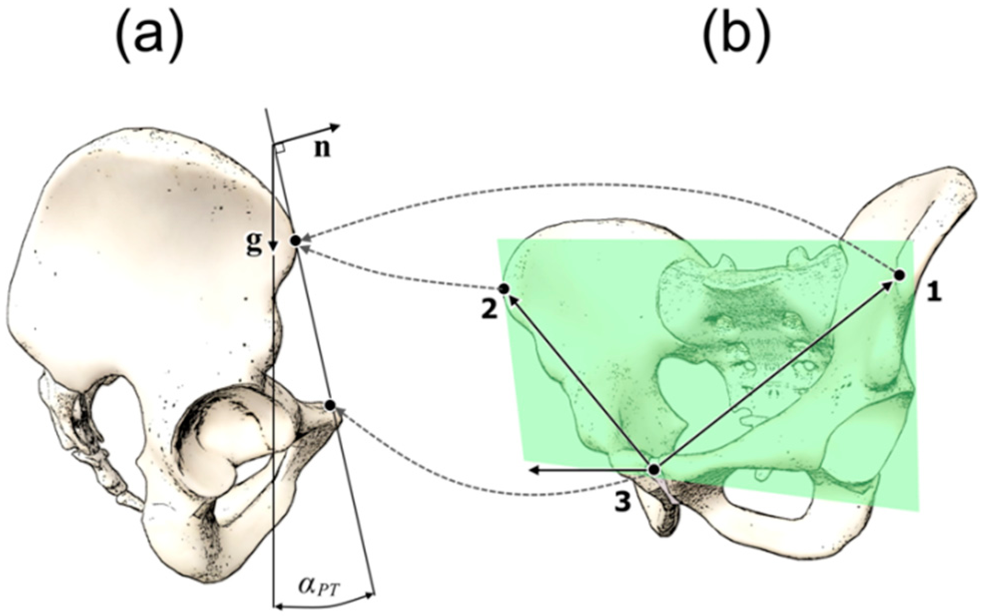
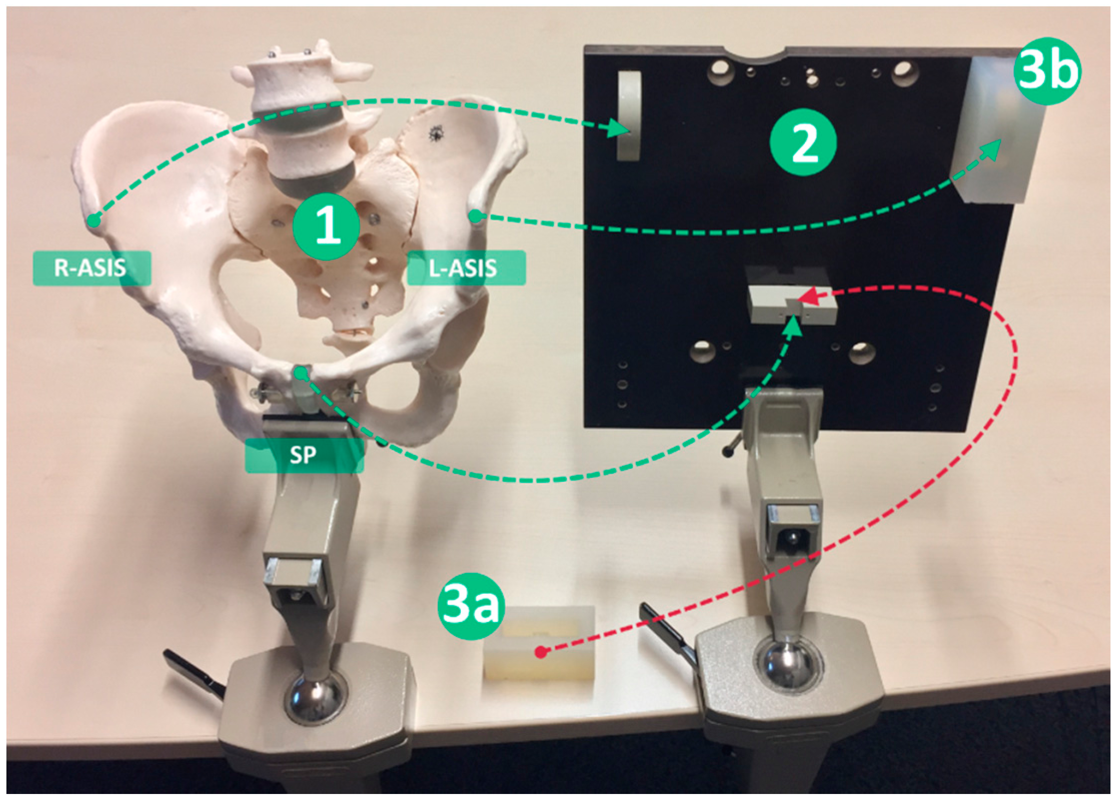
For correct alignment of the acetabular cup, knowledge of the pelvic orientation is essential. The anterior pelvic plane (APP) is commonly used as a superficial anatomical landmark during THA surgery, with most of the patients lying in the supine position. APP is defined as the plane through the right anterior superior iliac spine (right-ASIS), the left anterior superior iliac spine (left-ASIS) and the symphysis pubis (SP) (
Figure 1b). The angle between the APP and the coronal (frontal) plane is defined as pelvic tilt angle (PT) (
Figure 1a).
Pelvic tilt changes are associated with a change in the spatial orientation of the pelvis and consequently influence the position of the acetabular component. Therefore, PT differences between the supine and the upright position may be responsible for THA dislocations, if cup alignment is only based on PT values measured in the supine position. With mathematical correction algorithms, it is possible to determine the functional position of the cup based on PT measurements as demonstrated in two former studies [
14,
15].
The aim of this secondary data analysis was to investigate the extent to which PT angles of symptom-free young adults vary when measured in the supine and in the upright position. Furthermore, the concurrent validity of the measurement system was tested against a digital inclinometer on a pelvis phantom model.
2. Materials and Methods
2.1. Study Design
This is a secondary data analysis. The data used to investigate the research question was originally collected to investigate the intra- and inter-rater reliability of the smartphone-based navigated ultrasound system used as measurement tool [
16]. The study used a repeated measures design. Two raters (medicine doctors) trained with the system carried out the measurements on symptom-free young adults. One engineer carried out the measurements on the pelvis phantom model. The measurements took place at the Schön Klinik Hamburg, Hamburg, Germany.
The Medical Ethics Commission of the Federal State of Hamburg, Germany, approved the original research proposal on 20 May 2016 (Approval code: PV5216).
2.2. Subjects
A convenience sample of asymptomatic young adults was used. The sample consisted of 12 healthy subjects (eight women and four men) recruited from the staff of the clinic. All subjects were informed about the study and asked to participate. Before participating, all subjects were required to read and sign an informed consent form. The inclusion criteria were the following: the subjects should be between 18 and 30 years old, free from hip or lower limb pathologies in their history, and free from acute health complaints.
2.3. Measurement System
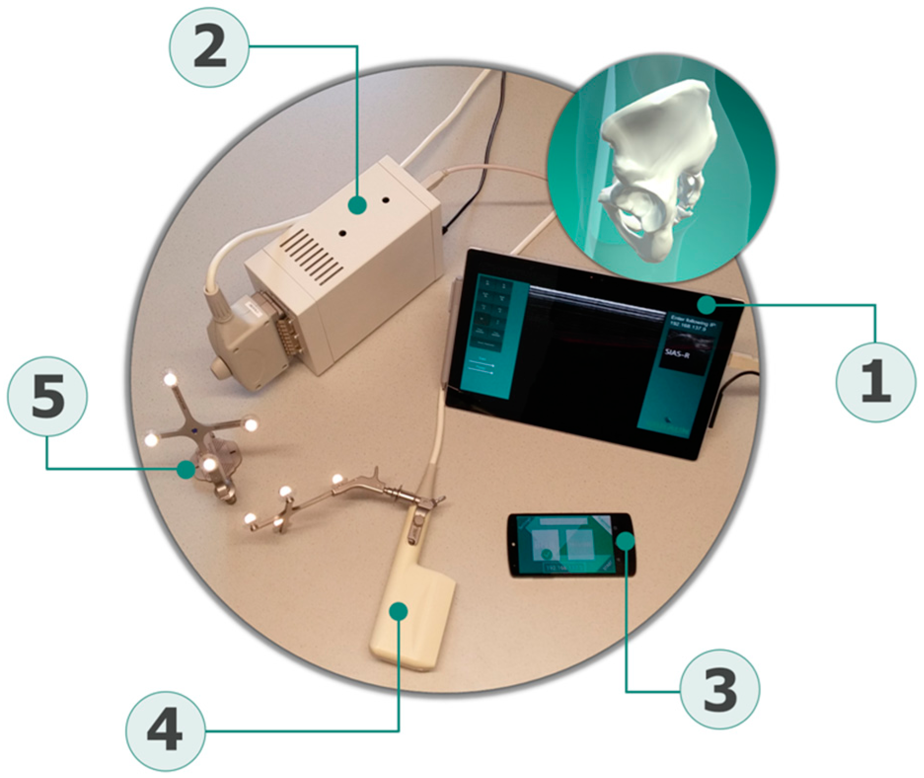
The novel measurement system used for PT assessments is composed of four components: a newly developed tracking software application that runs on a commercial smartphone and acts as a handheld tracking and sensing unit (iPhone 6, Apple Inc., Cupertino, CA, USA); two sets of position recognizable and referenceable rigid bodies (Aesculap AG, Tuttlingen, Germany); a certified ultrasound device (Echo Blaster 128, Telemed, Vilnius, Lithuania) attached to a trackable ultrasound linear transducer (3–7 MHz linear transducer with a sound window of 80 mm), which serves as the determination tool of the pelvis bony landmarks; and a central unit consisting of a commercial tablet (Microsoft Surface, Redmond, WA, USA), which acts as the main contact point for the other components (
Figure 2).
The intra-rater reliability of the system when measuring PT angles was good to excellent and moderate to excellent for the supine and upright positions, respectively. Inter-rater reliability remained below the expected values, probably due to the imaging protocols, which were probably not described with enough detail [
16].
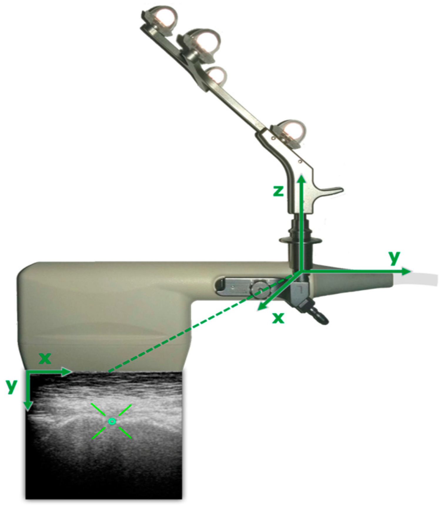
The digitization of the anterior pelvic plane was obtained through custom-programmed tracking software running on the smart localizer unit. To achieve a 3D reconstruction of the bony anatomy, the ultrasound probe is attached to a rigid body, enabling to receive the actual 3D position and orientation of the transducer (
Figure 3), which is tracked by the localizer unit (smartphone).
Each rigid body consists of four retroreflective spheres, and the tracking unit works on the principle of imageless navigation. The gravity vector is obtained from a combination of the Smartphone built-in sensors. Subjects individual PT is processed through an application running on the central unit. An ultrasound device is connected to the central unit via universal serial bus (USB) to display the sonographic image to the operator. The central unit receives the collected tracking data wirelessly via a direct connection based on a client-server model.
For each measurement, anterior pelvic plane was constructed from the obtained 3D coordinates of right and left ASIS and the symphysis pubis (SP). The recording sequence of anterior pelvic plane (APP) was taken from each operator first by recording the right ASIS, then left ASIS and finally the SP. After acquisition of bony landmarks, the operator has to mark the desired structure on each ultrasound image. The ASIS were marked as bright hyperechoic curved (convex) structures. The highest point on convex bony structure was marked. The symphysis pubis was marked as a darker hypoechoic line between two bony structures. With the referenced 3D coordinates of APP and the internal orientation sensor of the mobile unit, PT is computed by the central unit application using algorithms that were presented in a previous publication [
17]. The PT angle is calculated against the gravity vector (0°) in the upright position and against the horizontal vector (0°) in the supine position.
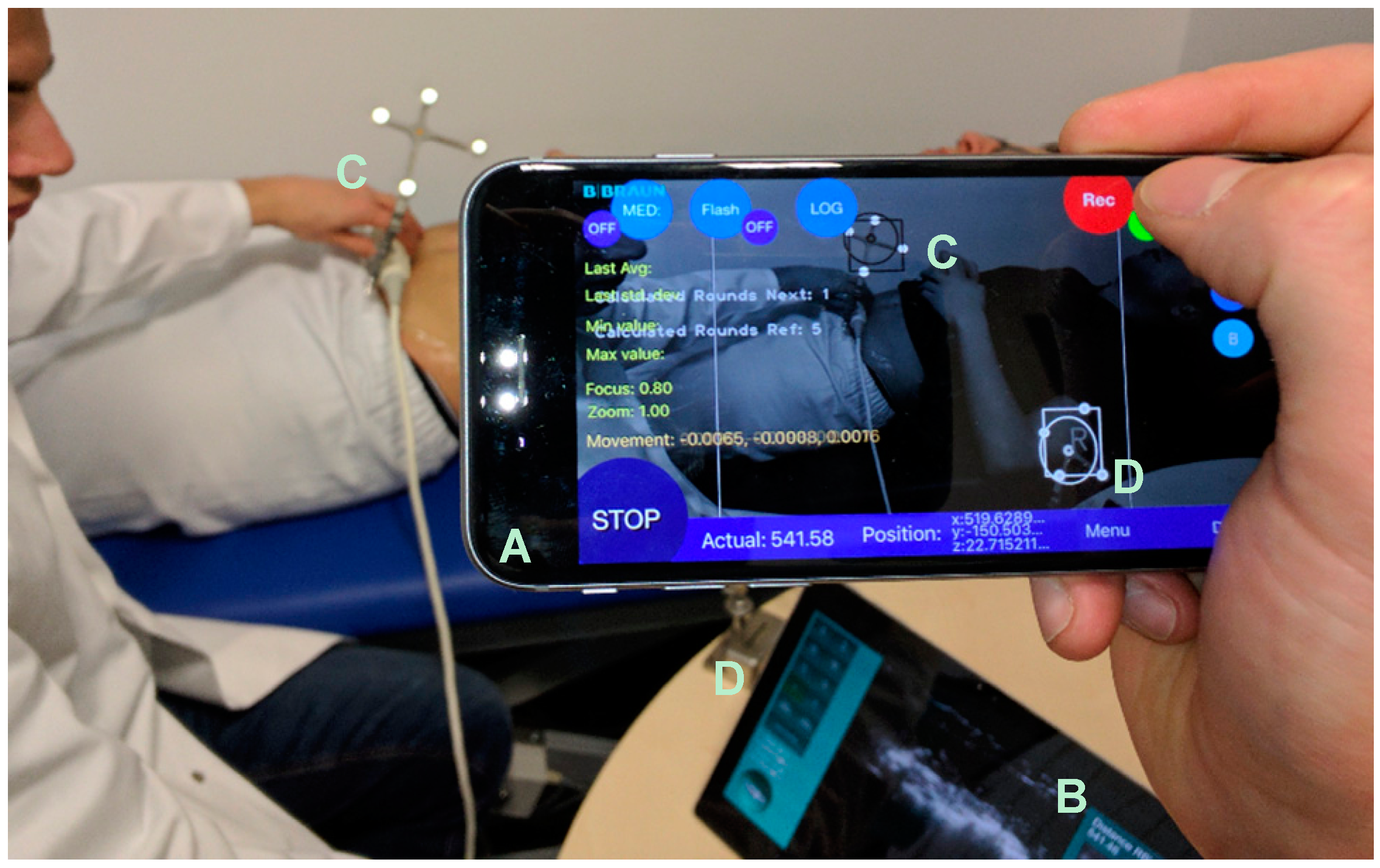
The tracking unit does not need to be attached to a fixed tripod and can be held by hand, which offers a high degree of flexibility (
Figure 4).
Due to this, the position of the tracking environment can be changed arbitrarily, and unfavorable measuring positions can be easily circumvented. For the determination of the PT, a second rigid body, acting as a reference point, is necessary to assign the coordinates taken by the mobile localizer unit.
2.4. Procedures
The subjects who agreed to participate were scheduled for PT assessments. Two raters carried out the measurements independently. The PT of each subject was measured three times consecutively in the supine and in the upright position by each rater. A total of three PT measurements per subject and per rater were available for the present secondary data analysis.
2.5. Pelvis Phantom Measurements
Concurrent validity and accuracy of the navigated ultrasound measurement system were tested in a pelvis phantom model (
Figure 5) against a calibrated digital inclinometer (ClinoBevel 1—USB, TESA Technology, Ingersheim, Germany) with a precision of ±0.052°.
The pelvis phantom model reproduces accurately the three bony landmarks of the pelvis that have to be tracked to build the APP. Twelve measurements were performed on the pelvis phantom model in both 0° supine and 0° upright positions. The landmarks on the pelvis phantom were covered with a tissue-mimicking material (Urethane rubber, ATS Laboratories, Inc., Bridgeport, CT, USA), which is attuned for ultrasound (Attenuation coefficient = 0.5 dB/cm/MHz ± 10%; Speed of sound = 1450 m/s ± 1.0% at 23°) and serves as short pre-offset for the landmarks. The pelvis phantom was fixed through a rotatable clamp on a table. The smart localizer was used handheld by a second examiner and about one meter away from target. An interval of about one minute was held between the measurement trials.
2.6. Statistical Analysis
A two-way mixed linear model with one fixed within-subject factor (body position) and one random between-subject factor (rater) was carried out to test whether body position and rater had significant effects on PT angles. Post hoc analysis was conducted for the within-subject factor (body position) with a t-test for paired samples upon the least squares means (= estimated marginal means). To ensure that the “trial order” had no effects on the measured PT angles a second model with two fixed effects (“body position” and “trial order”) was run.
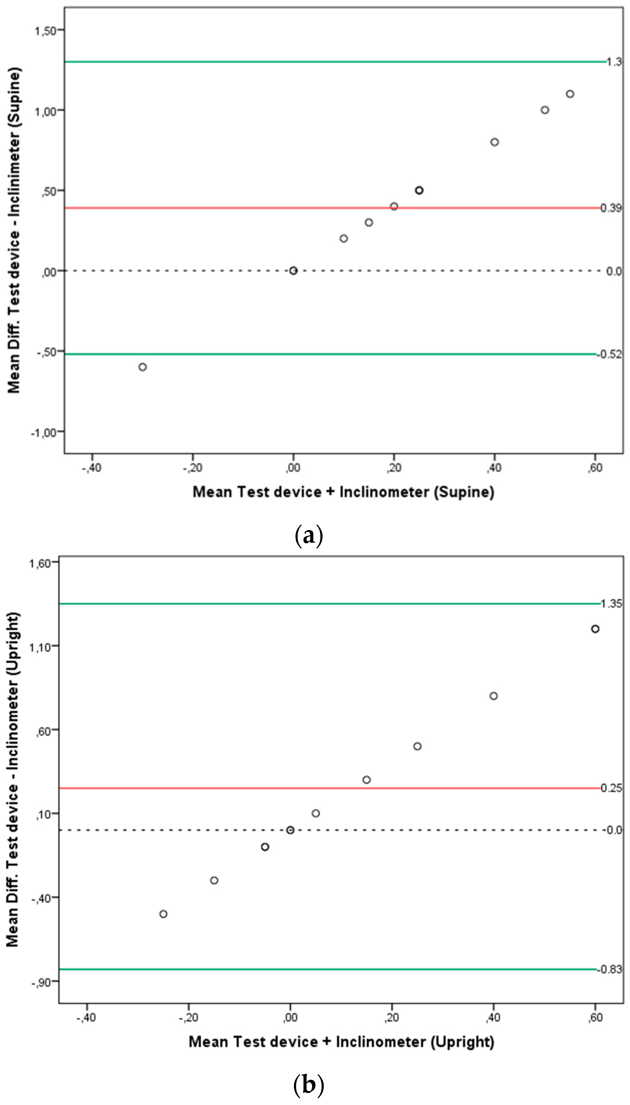
Bland-Altman plots were used to test for systematic bias (inter device variability: smart-phone based navigated ultrasound vs. inclinometer) on the pelvis phantom measurements. The mean difference and 95% limits of agreement (LOA), which were defined as the average difference ±1.96 × SD, were calculated [
18,
19]. The observed mean differences between PT angles measured with the navigated ultrasound system and the neutral PT position (0° = true average) of the pelvis phantom as measured by the digital inclinometer were also calculated as the accuracy measure of the measurement system on the pelvis phantom model.
For all tests, the level 0.05 was accepted as the criterion for statistical significance. All statistical tests were carried out with the SAS software version 9.4 (SAS Institute Inc., Cary, NC, USA).
3. Results
The mean age of the subjects included in the sample was 24.2 ± 3.3 years. Their mean body mass index (BMI) was normal (23 ± 1.3 Kg/m
2). For further demographic data details see
Table 1.
The measured PT angles are presented in
Appendix A (
Table A1). The mixed linear model revealed no significant main effects for the between-subject factor “rater” but significant main effects for the within subject factor “body position” (F
(2) = 67.4;
p < 0.001). Post hoc analysis showed that PT angles measured in the supine position significantly differed from PT angles measured in the upright position (
p < 0.001) (mean diff. = 8.1°; 95% C.I.: 6.7 to 9.5). The subjects’ pelvis in supine position was significantly more tilted anteriorly (mean PT = −7.3°, 95% C.I.: −10.6 to −3.9) than in upright position (mean PT = 0.8°, 95% C.I.: −2.5 to 4.1). At the same time, the trial order had no effects on the PT angles (
p = 0.5), and there was no interaction between “body position” and “trial order” (
p = 0.8).
The measured PT angles on the pelvis phantom are shown in
Appendix A (
Table A2). The average discrepancy between the smartphone-based navigated ultrasound system and the inclinometer (average bias) was not significantly different from zero in the upright position (mean diff. = 0.25;
p = 0.1), but it was significantly different from zero in the supine position (mean diff. = 0.39;
p = 0.01). Bland-Altman plots with the mean difference and 95% limits of agreement (LOA) are presented in
Figure 6a,b for the supine and upright positions respectively.
4. Discussion
A novel smartphone-based navigated ultrasound system was used in the present study to measure the PT angles of symptom-free young adults. The new measurement system used is noninvasive, and since the tracking unit is handheld, it offers a high degree of flexibility allowing PT measurements in different body positions and settings.
All subjects included in the sample were young (mean age = 24.2 ± 3.3 years), symptom free and had normal body mass indexes (BMI) (mean BMI = 23.0 ± 1.3 Kg/m2). This is considered by the authors as a study limitation since it narrows the external validity of the collected data. Assessing PT angles in subjects of older age with hip diseases like hip osteoarthritis or hip dysplasia and with higher BMIs may be associated with difficulties while searching the bony landmarks with the ultrasound transducer. In addition, the PT differences detected between the supine and upright position in this small group of symptom-free young subjects should not be used as reference PT values for other groups of subjects with different characteristics. Further studies to assess PT in other groups of subjects/patients are necessary and should be performed in the future.
After testing the intra- and inter-rater reliability of the system in the study, in which the present data was collected, the authors realized that the imaging protocol used for PT assessments needed a readjustment. While intra-rater reliability values were good, inter-rater reliability remained below acceptable marks [
16], showing that both raters were probably locating the bony landmarks differently. Differences in localizing the right and left ASIS could have led to these discrepancies. Therefore, in further studies, the right and left ASIS should be defined as the origin of the muscle Sartorius tendon.
As demonstrated by the measurements on the pelvis phantom, the system enables the assessment of PT angles with a high degree of precision. When measuring the PT angles in humans, there are some factors that can influence the accuracy of the measurements. One of these factors relates to the experience of the rater in getting the right image of the bony landmark. Another factor is the body position of the subject that is being assessed. By pressing the ultrasound transducer against the bony landmark, the rater can easily change the body position of the subject without noticing it. Especially in upright position, attention should be taken to avoid changes in the postural set of the subject evoked by the rater while accessing the bony landmarks.
The main finding of the present study was the significant difference found between PT angles measured in the supine and upright positions. A mean PT difference by 8.1° was statistically significant (p < 0.001). In supine position, a mean PT value of −7.3°, 95% C.I. (−10.6 to −3.9) indicated that the pelvis of the subjects was tilted anteriorly. In contrast, a mean PT of 0.8°, 95% C.I. (−2.5 to 4.1) in upright position indicated that the pelvis was more in a neutral or posterior tilt position.
In view of this finding, the question arises whether PT angle differences between the supine and upright position in patients submitting for total hip arthroplasty (THA) remain or increase in comparison to the values of symptom-free young adults presented in the present work. In a study on the rationale for PT-adjusted acetabular cup navigation [
20], the measured mean PT angles were −10.4 ± 7.4 and −5.0 ± 9.4 for the supine and upright position, respectively. In line with our results, the mean PT difference between both positions was statistically significant (
p < 0.001). However, the PT measurements were performed with computer tomography for the supine and standing X-rays for the upright position with the implied radiation exposure for the patients.
In a study by Abdel et al. [
12], the majority (58%) of dislocated THA had the cup within the Lewinnek safe zone. If cup alignment is only based on PT angles measured in the supine position, significant PT differences between the supine and upright positions may affect the stability of the hip negatively and lead to dislocations. Therefore, Dardenne et al. [
21] recommended that the notion of a “safe zone” should be revised to minimize the dislocation risk. PT changes with activity should be considered. This idea is reinforced by the results of a study by Pierrepont et al. [
22], in which the authors concluded that optimal cup orientation should be patient-specific and requires an evaluation of functional PT pre-operatively. In view of these recommendations, the measurement system used in the present study is promising because it is noninvasive and can be used to measure PT in different body positions.
The concurrent validity of the system showed no significant differences between both devices when measuring PT in the upright position. A mean difference of 0.39° was significant (p = 0.01) when the measurements of both devices were compared for PT assessment in the supine position.

 ,
, 