Smart Integration of a DC Microgrid: Enhancing the Power Quality Management of the Neighborhood Low-Voltage Distribution Network


Energy Systems Research Laboratory, Department of Electrical and Computer Engineering, Florida International University, Miami, FL 33174, USA
*
Author to whom correspondence should be addressed.
Inventions 2019, 4(2), 25; https://doi.org/10.3390/inventions4020025
Submission received: 25 March 2019
/
Revised: 12 April 2019
/
Accepted: 12 April 2019
/
Published: 17 April 2019
(This article belongs to the Special Issue Modeling, Planning and Optimal Management of Mini/Micro-Grid in Presence of Distributed Energy Resources)
Abstract
:The fast development of the residential sector regarding the additional integration of renewable distributed energy sources and the modern expansion usage of essential DC electrical equipment may cause severe power quality problems. For example, the integration of rooftop photovoltaic (PV) may cause unbalance, and voltage fluctuation, which can add constraints for further PV integrations to the network, and the deployment of DC native loads with their nonlinear behavior adds harmonics to the network. This paper demonstrates the smart integration of a DC microgrid to the neighborhood low-voltage distribution network (NLVDN). The DC microgrid is connected to the NLVDN through a three-phase voltage source inverter (VSI), in which the VSI works as a distribution static compensator (DSTATCOM). Unlike previous STATCOM work in the literature, the proposed controller of the VSI of the DC smart building allows for many functions: (a) it enables bidirectional active/reactive power flow between the DC building and the AC grid at point of common coupling (PCC); (b) it compensates for the legacy unbalance in the distribution network, providing harmonics elimination and power factor correction capability at PCC; and (c) it provides voltage support at PCC. The proposed controller was validated by Matlab/Simulink and by experimental implementation at the lab.
1. Introduction
The predicted massive utilization of photovoltaic (PV) systems in the residential sector is justified for several reasons. The efficiency of the PVs is improving, the cost of manufacturing is declining, and incentives provided by the utility have decreased the utility bills. Additionally, it is expected that the DC loads usage is increasing in the distribution network, such as the usage of new DC appliances and equipment in the residential sector (consumer electronics, LED lighting, and compact fluorescent lamps) [1]. Despite the benefits of the innovations in source and demand sectors, many power-quality problems are present in the distribution network that work against all these innovations. For example, the integration of rooftop PVs may cause severe voltage fluctuations and unbalance due to the uncertainty and the lack of availability of the irradiance [2,3,4,5]. Additionally, the increased usage of DC loads adds more harmonics to the distribution network [6,7]. This is because each individual DC load needs an individual rectifier to facilitate the connection of the equipment to the current AC network and provide power factor correction to comply with the utility policy [8,9]. Moreover, the expedite movement toward the usage of a sensitive component in residential, commercial, industrial, and traction applications such as refrigerators, televisions, computers, and switched-mode power supplies adds nonlinear and unbalanced loads to the distribution network [10]. Degrading the power quality of the power system network wears out the network component, increases the probability of system shutdown, and increases maintenance disbursal [11,12,13]. As a consequence, enhancing the power quality of the electric power network is a critical factor in the process of power generation and delivery.
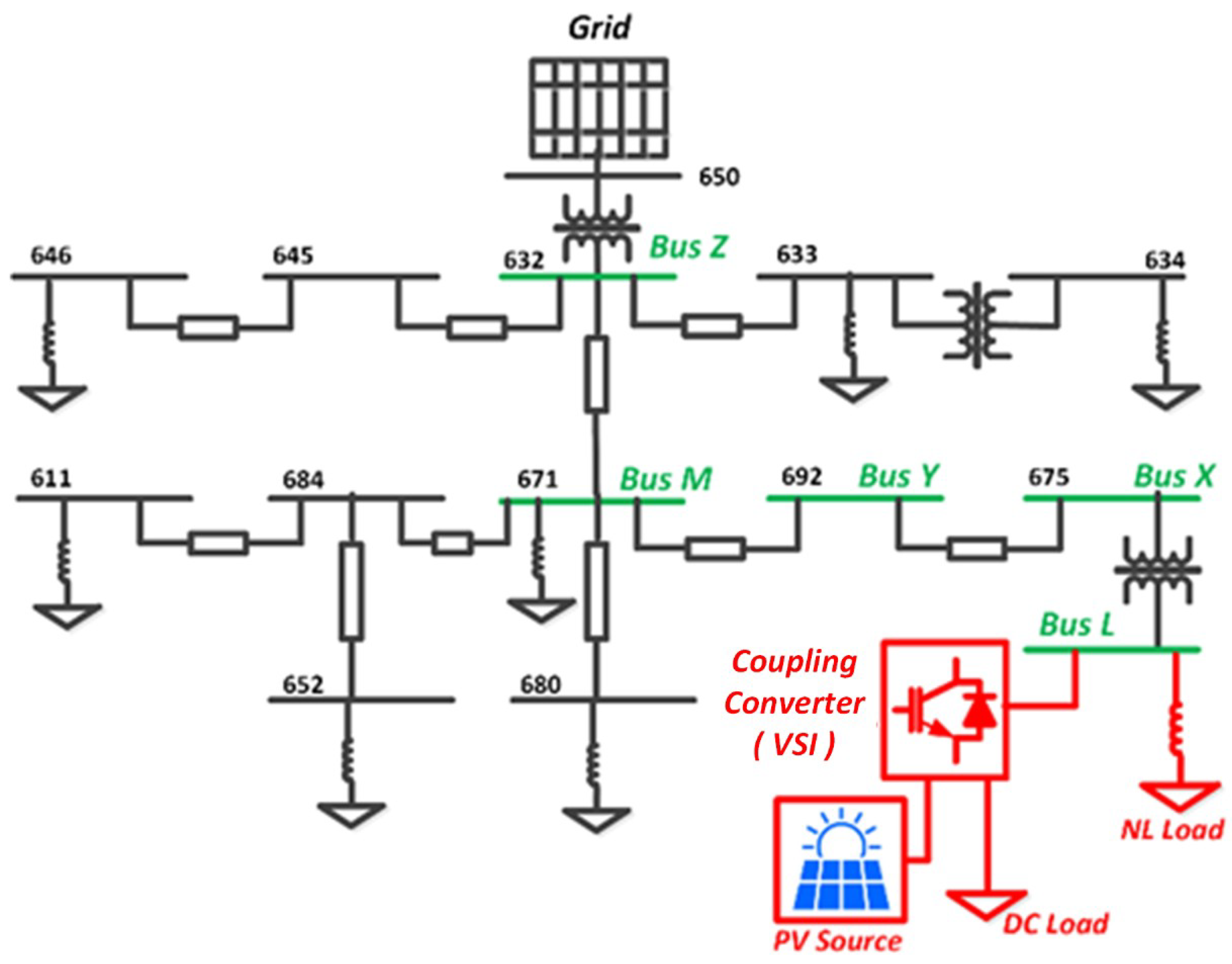
As a consequence, this paper proposes a smart integration of a DC microgrid to neighborhood low-voltage distribution network (NLVDN), as depicted in Figure 1. The DC microgrid is connected to the NLVDN through three-phase voltage source inverter (VSI), in which the VSI works as a distribution static compensator (DSTATCOM), and the DC link provides an integration point for the PV and the DC native loads. The DC microgrid is composed of a photovoltaic (PV) source and DC loads connected to the DC side, DC link capacitor bank, and three-phase VSI to integrate the NLVDV.
The electrical regulation standards in distribution networks such as power factor and harmonics levels are applied on all AC loads connected to the current AC network. Some of these regulations define the interconnection requirement of the distributed generation (DG) units in low-voltage distribution systems [14,15,16]. Others determine the interconnection regulation for the electric loads, such as home appliances [17,18,19]. The main concern for the utility companies is the massive utilization of loads in current homes that do not comply with the standard regulation and degrade the power quality of the power system network [20].
The IEEE 1547 is one of the power-quality standards, which define the harmonics and total harmonic distortion (THD) levels. Several works introduce different ways to mitigate harmonic components and compensate for reactive current, negative harmonics. Some use the injection of the negative reactive current to the power network to reduce the harmonics and provide power factor correction [21,22,23,24]. Another approach allows the simultaneous compensation of the harmonics and reactive power issues known as the active power filter (APF). In addition, it can provide compensation for the system load unbalance and compensate for voltage fluctuations at the point of common coupling (PCC). There are different topologies of APF such as series and shunt. The performance of the APF depends on the accuracy of selecting a suitable method to extract the undesired current. The synchronous reference frame (SRF) method is used in three-phase balanced systems [25,26]. Another effort is based on instantaneous power theory in three phases, known as the unbalanced system [27,28,29,30]. However, the previous approach requires extra computation to process the three phases current and the voltage measured, which affects the cost of implementation. In this paper, the smart integration of a DC microgrid to NLVDN was demonstrated. The DC microgrid is connected to the NLVDN through a VSI, in which the VSI works as a DSTATCOM and the DC link provides an integration point for the PV and the DC native loads. The proposed technique is capable of compensating the reactive power, unbalance, and harmonics demanded by three-phase non-linear loads, and unbalance connected to the distribution side improves the power quality. Furthermore, it is able to prevent the source from getting overloaded by providing active power support to the load. Unlike previous STATCOM work in the literature, the proposed controller of the VSI of the DC smart building allows for multiple functions, as follows: (a) it enables the bidirectional active/reactive power flow between the DC building and the AC grid at PCC, (b) it compensates for the legacy unbalance in the distribution network, providing harmonics elimination and power factor correction capability at PCC, and (c) it provides voltage support at PCC. A simulation model based on MATLAB/SIMULINK is modeled to validate the functionality of the proposed control algorithm. Moreover, the experimental setup is laboratory implemented to prove the validation of the performance experimentally. The results depict that the developed controller succeeds to maintain bi-directional power flow controllability, while simultaneously acting as an active power filter to ensure improved power quality at the PCC under various loading conditions.
The paper is arranged as follows: in Section 2, a description of the system under study and the suggested control technique is demonstrated. In Section 3, simulation results are presented and inquired about to validate the proposed technique. In Section 4, experimental results are presented to evidence the validation of the controller’s execution experimentally. Finally, in Section 5, the conclusions of the paper’s contributions are listed.
2. Proposed System Description and the Control Technique
2.1. The Proposed System Description
In order to evaluate the effect of a smart load on the distribution system, the smart load was connected on the IEEE 13-bus test feeder system. The test system was modified to include the smart load. Figure 1 shows the standard IEEE system under study, and the smart load was connected at bus 675. The network buses 632, 671, 692, and 675 were renamed as buses Z, M, Y, and X, respectively. The effect of imposing the smart load on the distribution system was studied on the pass from bus Z to bus L. The smart load contained a non-linear load, which was connected directly to bus L. The PV source and the DC load were connected to grid via a coupling converter. On the one hand, the converter worked to harvest the PV energy and drive the DC load, while the proposed control system will provide ancillary service and ensure the power quality at the point of the common coupling, which will positively impact the distribution grid.
2.2. The Control Technique
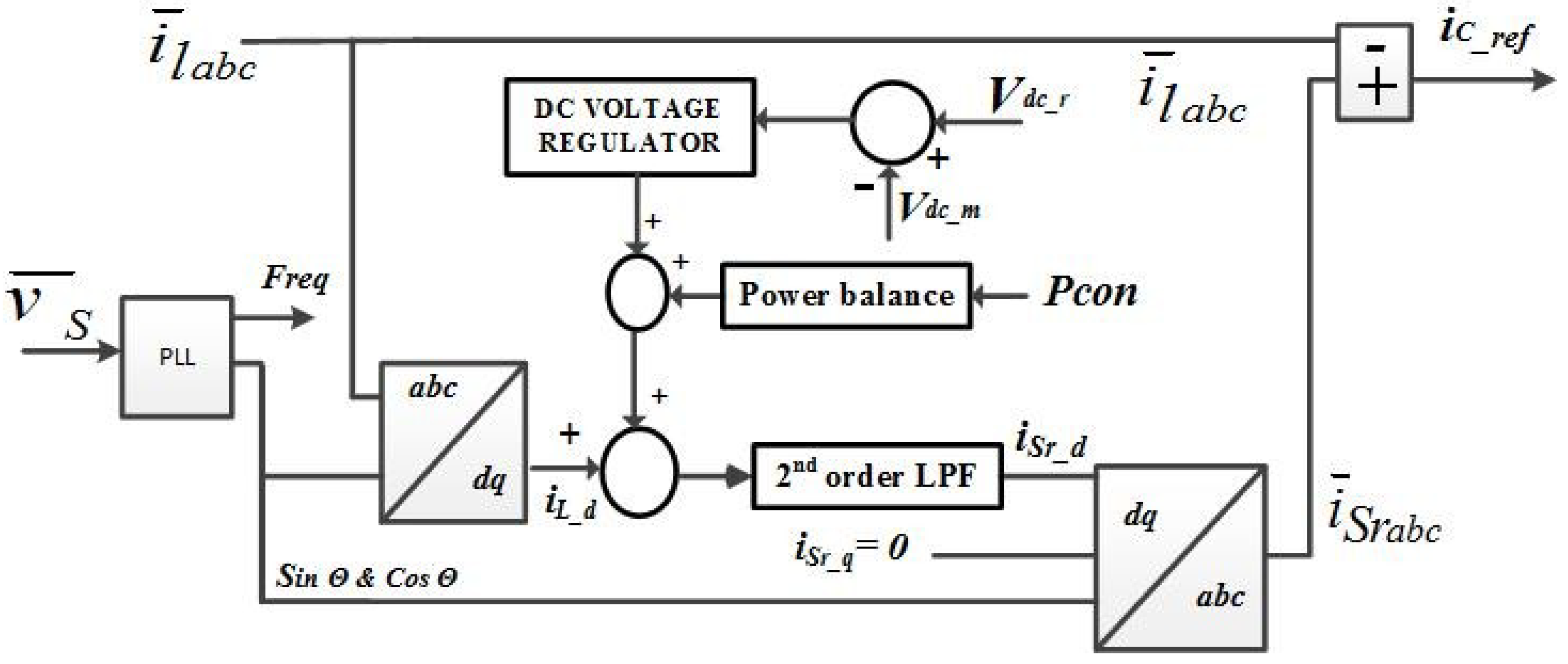
The main functions of the control technique are canceling the harmonics caused by the non-linear loads and compensating for the load unbalance caused due to the existence of single- and three-phase powered loads that are arbitrarily distributed and act as power factor corrector (PFC) at PCC. The proposed algorithm is based on a modified version from vector decoupled control in which the instantaneous three phases current was measured and transformed from ABC to DQ reference frame. This revised version of vector decouples control technique is capable of dealing with unbalanced and balanced systems. A block diagram depicting the control algorithm is shown in Figure 2.
This controller is based on the park’s transformation, in which the three-phase current is converted to direct and quadrature current ild and ilq, respectively. This calculated current ild has been analyzed. The results provide a DC value representing the fundamental active component and AC value representing the harmonic components, unlike the vector decouple control method, which uses the high pass filter to isolate the AC component from ild. The proposed modified vector decouple control method uses a low-pass filter with a cut-off frequency of 75 Hz. The DC component of ild is obtained by passing ild through the low pass filter. The low pass filter output represents the magnitude of the fundamental active current component existing in the load current. To regulate the DC bus voltage, a power balance technique is used to control the power delivered and submitted to/from the DC link. To maintain the power balance through the DC microgrid, the amount of power controlled by the grid tie converter needs to be obtained, as given in (1), which represents the difference of power between the PV power and the local DC load power. The active power component is controlled as given in (2). Since the synchronous reference frame d-axis is aligned with the three-phase voltage angle, Vq will be equal to zero. Then, the Id reference is calculated in (3), as follows:
in which a PI controller will preserve this balance and provides a direct current component Idvr to represent the voltage regulator direct current share. This voltage regulator direct current component can be calculated from (4) to (6), as follows:
The previous component is added to the calculated ild (low pass filter output). Then, by using inverse Park’s transform, the three-phase sinusoidal current reference is obtained. The quadrature current component ilq and zero current component il0 are set to zero, since the target is to capture the active fundamental component only. Consequently, the obtained three-phase sinusoidal current reference is subtracted from the load current. The resulting reference current represents all harmonics and reactive components associated with the load current, plus a fundamental component necessary for power balancing. The obtained three-phase sinusoidal reference is subtracted from the load current to obtain the final current reference controls the injected current to the AC side. Therefore, the injected current will contain a component to balance the power flow and component to counteract the harmonics and unbalance values at the original non-linear load, which will result in a pure current from the utility side at the PCC. Also, it will maintain the load balance at bus L.
3. Results and Discussion
3.1. Case Study A
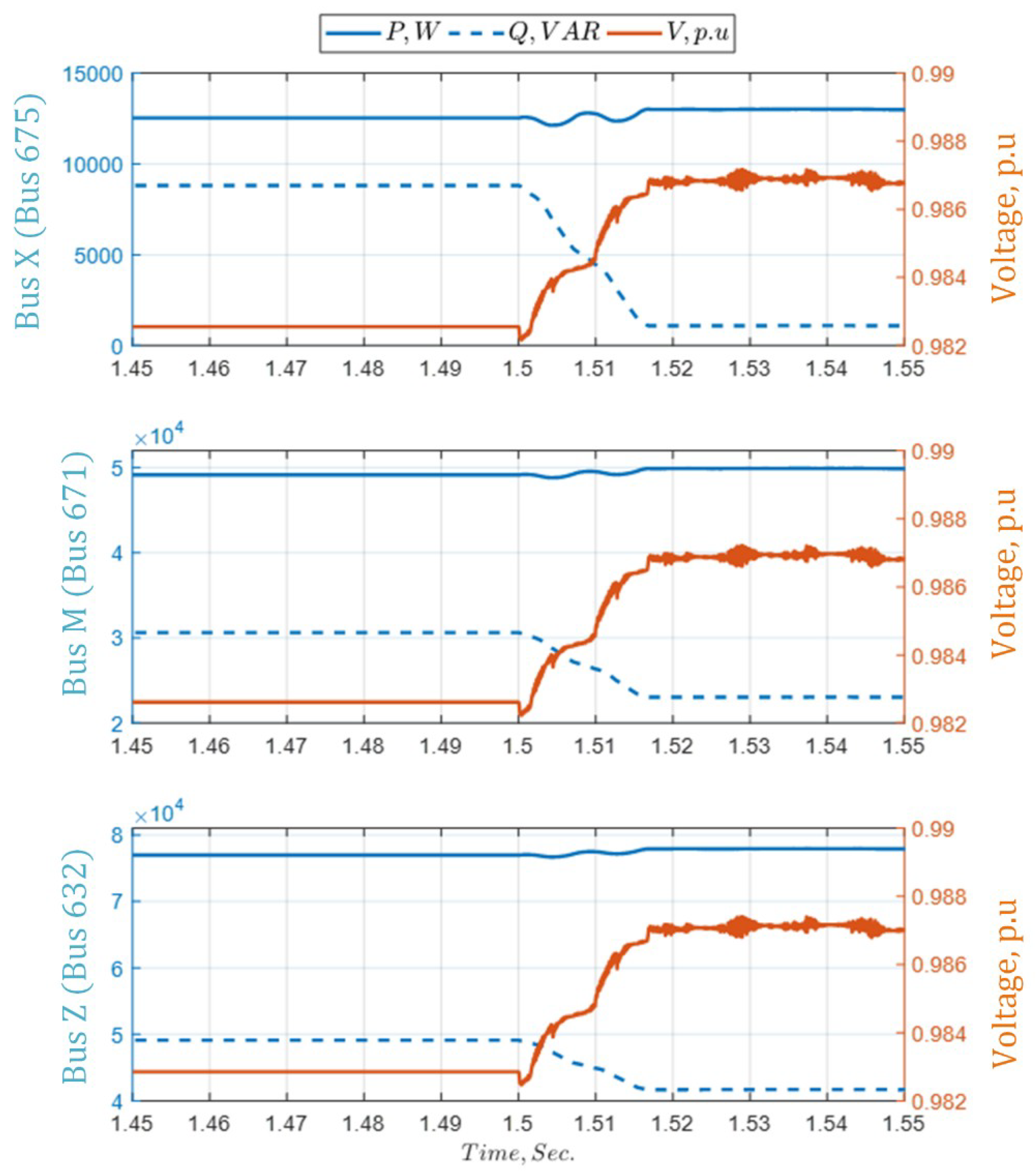
In this case study, the smart load control system is applied to t = 1.5 s. Moreover, the following figures depict the comparison between the IEEE 13-bus system before and after the smart load application. To show the improved performance after applying the smart load, Figure 3 shows the effect of the smart load on active power, reactive power, and voltage profiles at bus X, M, and Z. The results show that the active power capability for the whole pass of the smart load is increased.
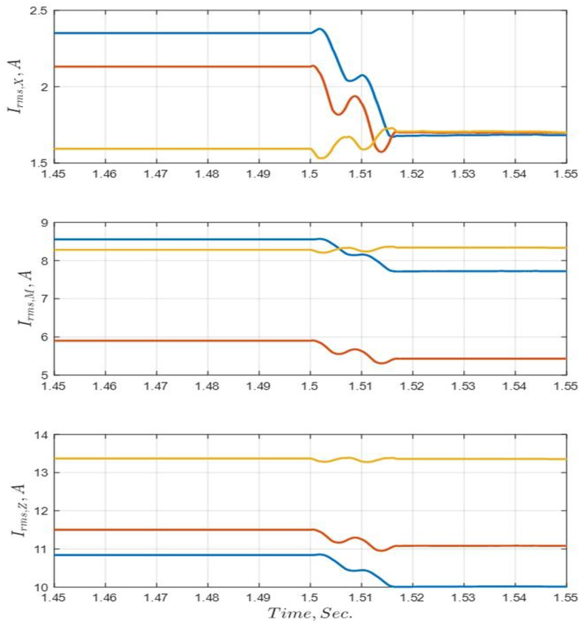
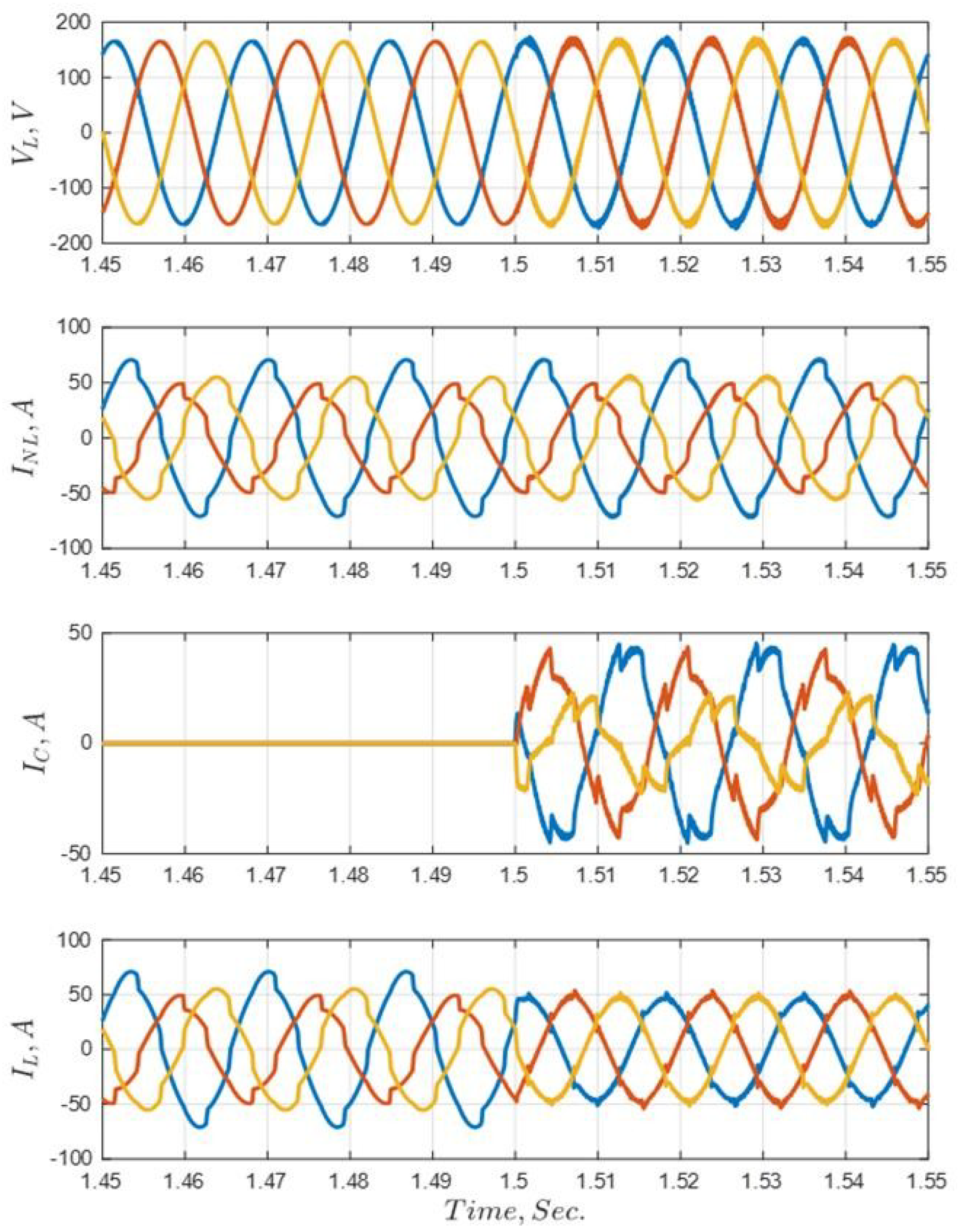
In addition, the reactive power at the same pass is reduced, which improves the power factor and the voltage profile at these points. Correspondingly, as shown in Figure 4, the unbalanced current ratio is diminished through the distribution bus pass, especially at point X. To clearly show the effect of the smart load application, the instantaneous values of three-phase voltages, load currents, coupling converter currents, and bus L injected currents are illustrated in Figure 5. The figure demonstrates that the non-linear load and the converter compensation current to balance the bus L (PCC) three-phase current.
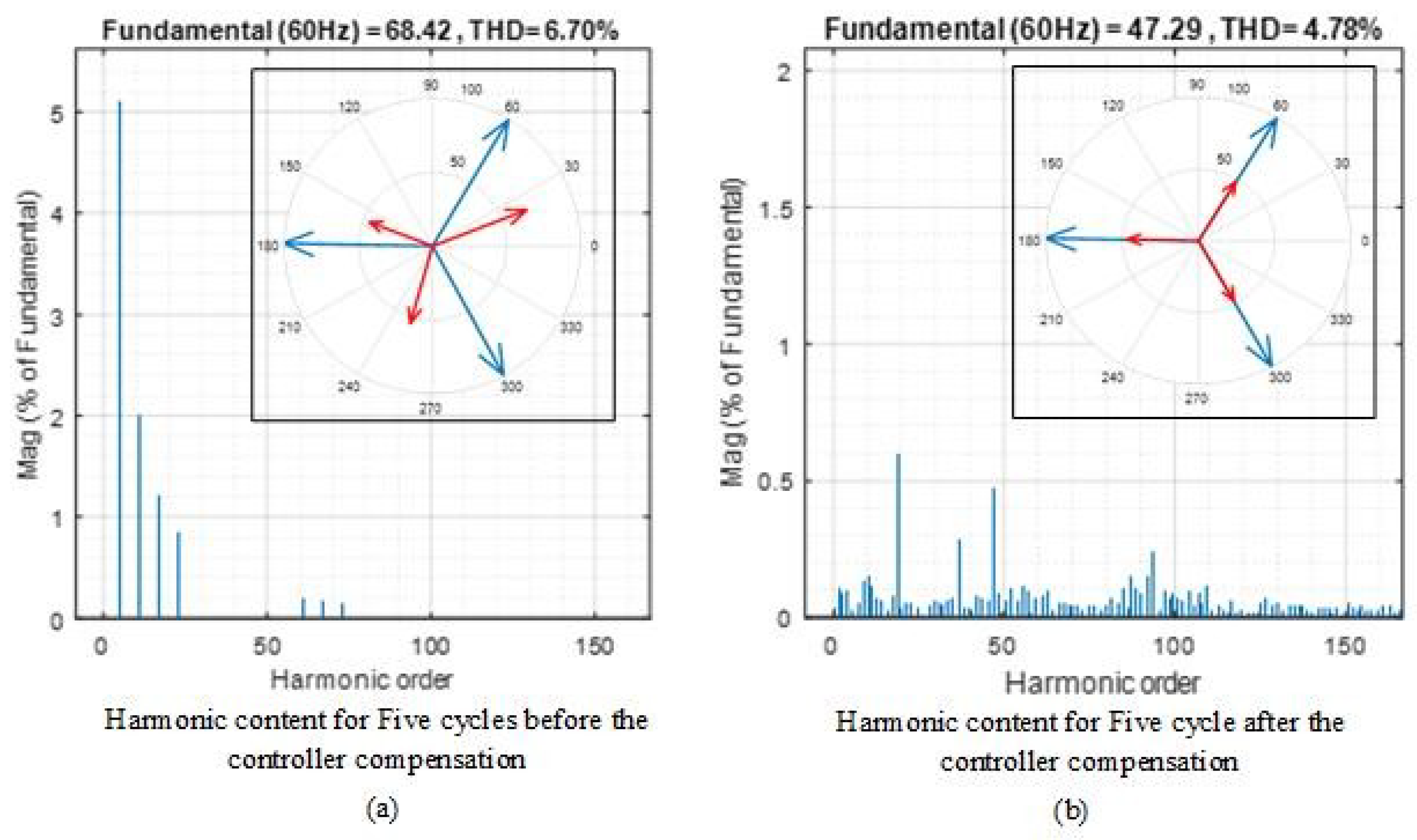
Analytically, Figure 6 illustrates the harmonic analysis and vector diagram for five cycles before and after the controller compensation effect. In Figure 6a, the total harmonic distortion was 6.7%. In addition, the current vector is not only unbalanced but also is shifted away from the voltage angle. On the other hand, Figure 6b shows the effect of the smart load control system; the total harmonic distortion is reduced to 4.78% with balanced current, and the power factor is improved toward unity.
3.2. Case Study B
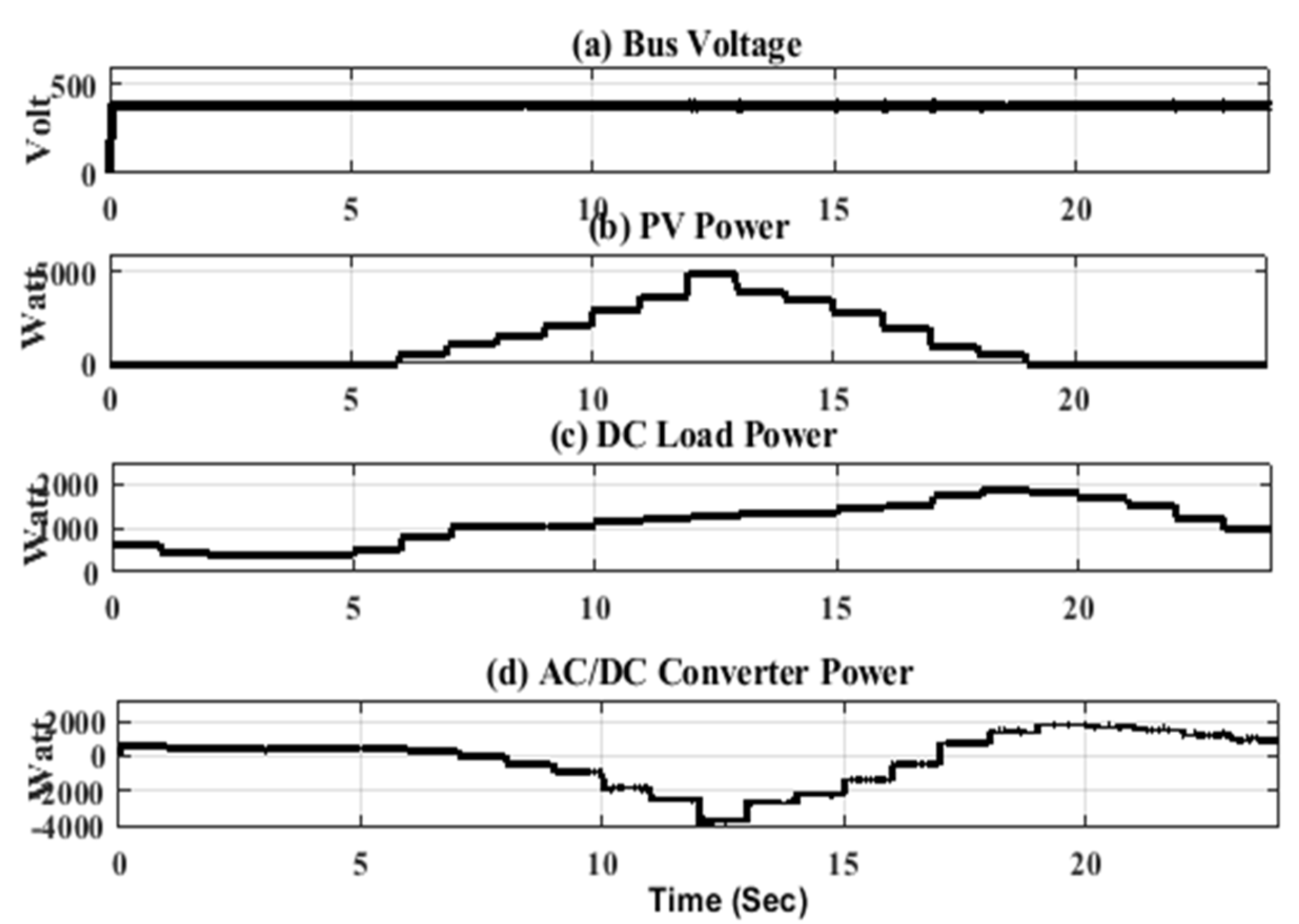
In this case study, the controller is examined to verify the capability for providing bi-directional power flow operation in addition to the power quality solving solutions. The simulation time is scaled to 24 s to represent a daily operation of 24 h. The controller is examined under severe bidirectional loading conditions to prove its capability to deal with such a load pattern. The DC voltage of the DC link bus is shown In Figure 7a. It is noticed that the voltage is consistent at a constant value (380 V) during the whole running operation. Even at the load transition instant, the bus voltage ripple fluctuates between 370 to 390 V. This ripple does not exceed the 5% ratio allowed by the standards. The PV output power profile is shown in Figure 7b. The local DC load power of the microgrid is shown in Figure 7c, and the power for the grid tie converter is shown in Figure 7d. It can be noticed that the grid tie power between 0 to 7 s and 17 to 24 s is positive, which indicates that the converter power flows from AC grid to the DC microgrid (the converter is working in rectifier mode). The reason for this is that in these intervals the PV power is insufficient to feed the local DC load, so the converter extracts power from the AC grid to supply the deficit in the DC microgrid local load. However, between 7 and 17 s, the grid tie power is negative, which indicates that the converter power flows from DC microgrid to AC grid (the converter is working in the inverter mode). The reason for this is that in these intervals, the PV output power is exceeding the local DC power, so inverter extracts power from the DC microgrid to support the local AC load on the AC utility side. Besides, the grid tie converter control proves its capability to control the power flow between both sides; it also provides power quality solutions as illustrated in the description of the next figures.
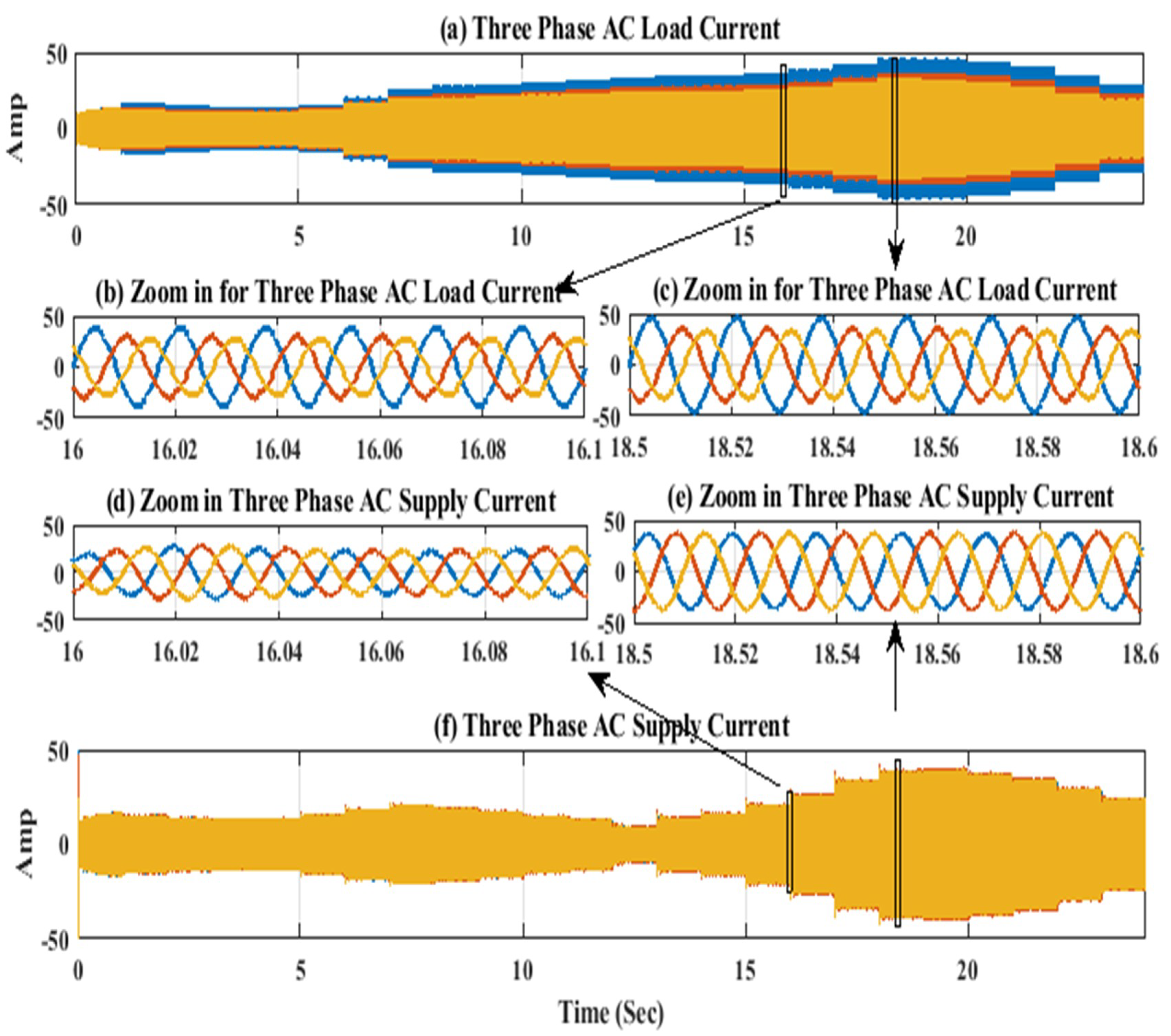
The three-phase AC load and source currents are shown in Figure 8a,f, respectively. Figure 8a shows the load current is an unbalanced, three-phase current, which is one of the problems that the controller has to tackle. Figure 8b,c gives a close view of Figure 8a and shows the load current at two different intervals to demonstrate the performance of the system in both rectifier/inverter modes. It is noticed that the current waveforms suffer from noticeable distortion due to the existence of a nonlinear load. It can be seen in Figure 8d,e that the three phases are balanced and the current waveforms are uniform, which implies the ability of the controller to mitigate harmonics and compensate for unbalances under both modes of operation.
4. Hardware Implementation and Experimental Results
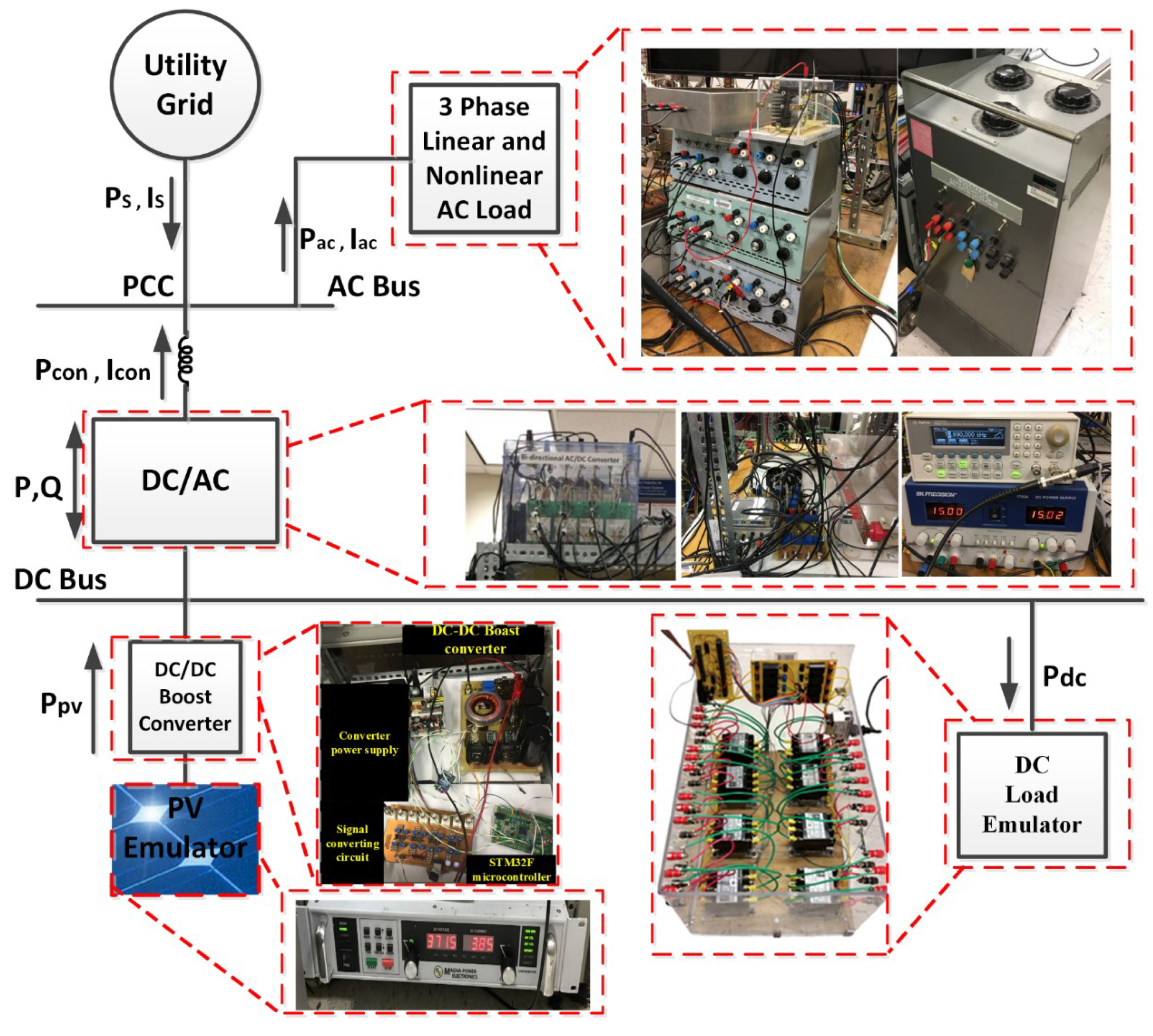
To investigate the feasibility of the proposed control technique, a hardware setup was established as depicted in Figure 9. The DC building was connected at the PCC through DC/AC converter. It was implemented in the power system test-bed (Energy System Research Laboratory, Florida International University) [31] and consisted of AC and DC zones connected through an AC–DC converter. The DC zone was represented by a DC bus, where its voltage was set to 380 V, along with a DC load emulator to represent load appliances connected to the DC side and a PV emulator to represent a roof-top PV source. The PV emulator, represented by XR SERIES DC power supply offered by the MAGNA-POWER ELECTRONICS, was programmed to emulate the PV I-V characteristics [32]. It was interfaced with the DC bus through a DC-DC boost converter to extract maximum power generated by the PV system. The mathematical modeling of the PV system and the converter MPPT controller were built within the MATLAB/SIMULINK environment and executed with the DSpace 1104 real-time interface. The DC load emulator was comprised of a combination of eight resistors with different values (1, 5, 10, 20, 30, 40, 50, and 60 Ω) in a particular arrangement [33]. In addition to these load resistor combinations, eight controlled switches were used to change the connection topology, which changed the values of the equivalent load resistors to obtain different load patterns. The central concept of operation was based on sending control signals to the switches to change their states (on/off). By changing their states, the equivalent load resistance changed. The control commands were generated from a load profile generator developed in the LabVIEW environment. The control commands were transferred through the PCI 6025E card to a circuit. This circuit was based on TEXAS INSTRUMENT inverting buffer module sn7406n. This module contained six inverters with open collector output. The RMS values for the voltage in the AC zone was set to 208 V. The AC bus was connected to the utility grid at PCC. Additionally, different load models were designed to represent the AC load pattern [34]. One of the passive loads that was built had a switching capacity of 10 levels parallel of resistive loads from 300-W to 3-kW power in steps of 300-W at a nominal voltage that could be switched to emulate various load patterns.
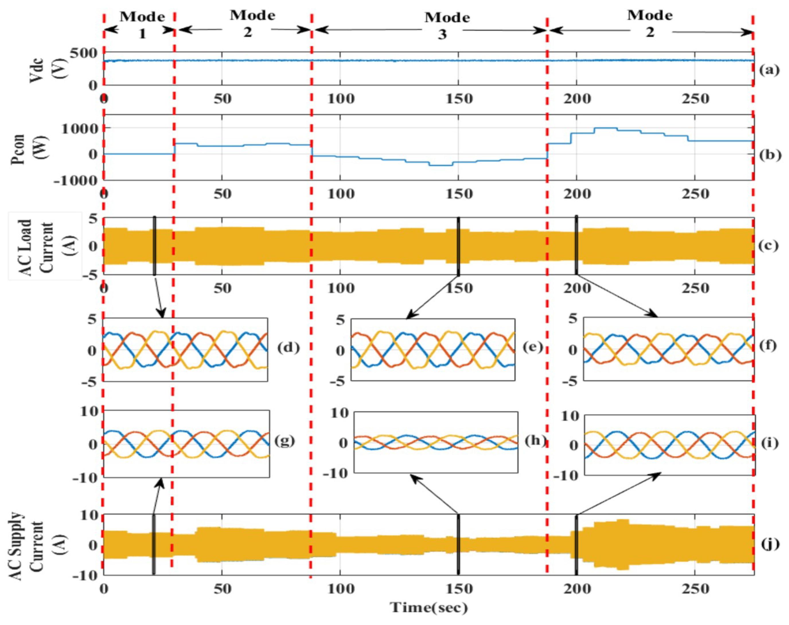
The parameters of the main components of the hardware setup are given in Table 1. The experimental results are shown in Figure 10; they show the capability of the proposed algorithm to compensate for unbalance and nonlinearity of the load current in different modes of operation. This figure is divided into four regions separated by the red-dashed line. These four regions represent three different modes of operation. In mode one (interval 0–28 s), the converter is working as an APF for the AC load but without any exchange in power between AC and DC zones. In mode two, (interval between 28–88 and 188–278 s), the converter works as an APF and rectifier in which the power is transferred from the AC side to the DC side. In mode three (interval between 88–188 s), the converter works as an APF and inverter in which the power is transferred from the DC side to the AC side.
The DC voltage of the main DC bus is shown in Figure 10a. The voltage is stable during the whole operation at 380 V. The ripple in the voltage fluctuates is in an acceptable range between 370 to 390 V at the instant of load transition. This small fluctuation in the DC bus voltage is compatible with the standards, as it does not exceed 5%. The grid tie converter power is shown in Figure 10b, which explains the bi-directional power flow between the AC grid and the DC microgrid. It can be noticed that the grid tie power between 30 and 100 s, and 188 and 278 s, is positive, which indicates that the converter power flows from AC grid to the DC microgrid (the converter is working in rectifier mode). However, between (100–188 s), the grid tie power is negative, which indicates that the converter power flows from DC microgrid to AC grid (the converter is working in the inverter mode).
In response, the converter control verified its capability to control the bidirectional power flow between the DC building and the AC grid. The three-phase AC load and source currents are shown in Figure 10c–j, respectively. Figure 10d–f gives a close view of Figure 10c at modes one, two, and three, respectively. It is clear there is noticeable distortion in the current waveforms in relation to the existence of nonlinear loads. Figure 10g–i, give a close view of Figure 10j at modes one, two, and three, respectively.
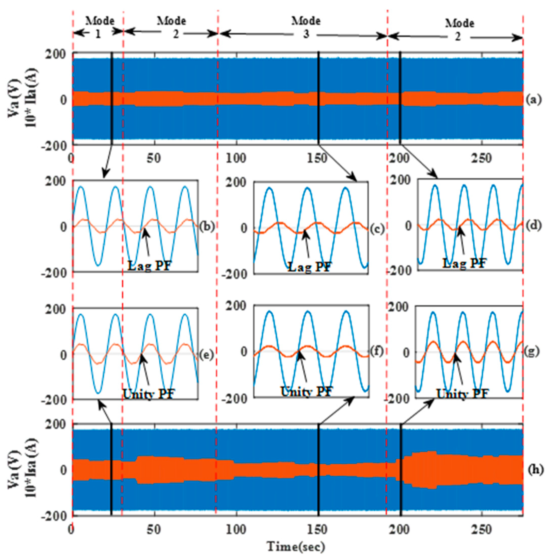
The controller has the capability to mitigate the harmonics and compensate for unbalances under all modes of operation. As is seen in Figure 10g–i, the three-phase currents at the source side are balanced. This indicates that the grid tie converter’s controller succeeded in cancelling out power quality issues (distortion and imbalance) from the source side. In order to validate the controller capability to improve the power factor, Figure 11 is shown. Figure 11a shows Phase A’s voltage versus Phase A’s load current. Figure 11h shows the Phase A voltage versus Phase A supply current. Figure 11b–d gives a close view of Figure 11a at modes one, two, and three, respectively. It is noticed that the current waveform is out of phase and lagging behind the voltage waveform, implying the involvement of a lag power factor. Figure 11e–g gives a close view of Figure 11h at modes one, two, and three, respectively. It can be seen that the current waveform is in phase with the voltage waveform, implying the involvement of unity power factor. Thus, the proposed control algorithm ID succeeds to correct the power factor for the system.
5. Conclusions
In this paper, the smart integration of a DC microgrid to a NLVDN is proposed. The DC microgrid connected to the NLVDN through a VSI, in which the VSI works as a DSTATCOM. Unlike previous STATCOM work in the literature, the proposed controller of the VSI of the DC smart building is multifunctional: (a) it enables the bidirectional active/reactive power flow between the DC building and the AC grid at PCC; (b) it compensates for the legacy unbalance in the distribution network and provides harmonics elimination and power factor correction capability at PCC; and (c) it provides voltage support at PCC.
A simulation model based on MATLAB/SIMULINK is modeled to validate the functionality of the proposed control algorithm. Moreover, the experimental setup is laboratory-implemented to prove the validation of the performance experimentally. The results depict that the developed controller succeeds to maintain bi-directional power flow controllability, while simultaneously acting as an active power filter to ensure improved power quality at the PCC under various loading conditions.
Based on the simulation and the experimental results, it can be deduced that the compensation for reactive power and harmonics has been achieved effectively. The source current is balanced, sinusoidal, distortion-free, and with an improved power factor. The %THD reduced significantly after compensation. It can be noticed that all of the previously mentioned benefits have were provided at the PCC of the distribution network. However, it also affected the neighborhood buses by providing reactive power and voltage support. To conclude, more smart integration of DC buildings/microgrids will help us tackle the distribution network problems regarding the rise of renewable energy penetration.
Author Contributions
A.F.E., designed the proposed controller, built the simulation model, conducted the experimental validation, and wrote part of the paper. A.A.S., implemnted the distribution network model, and wrote part of the paper. O.A.M. is the main supervisor who led the project, checked the results and edited the manuscript.
Acknowledgments
This work was partially supported in part by the U.S. Department of Energy and the Office of Naval Research.
Conflicts of Interest
The authors declare no conflicts of interest.
References
- Cvetkovic, I.; Boroyevich, D.; Mattavelli, P.; Lee, F.C.; Lucia, O.; Sarnago, H. Design of Home Appliances for a DC-Based Nanogrid System: An Induction Range Study Case. IEEE J. Emerg. Sel. Top. Electron. 2013, 1, 315–326. [Google Scholar]
- Parchure, A.; Tyler, S.J.; Peskin, M.A.; Rahimi, K.; Broadwater, R.P.; Dilek, M. Investigating PV Generation Induced Voltage Volatility for Customers Sharing a Distribution Service Transformer. IEEE Trans. Ind. Appl. 2017, 53, 71–79. [Google Scholar] [CrossRef]
- Chamana, M.; Chowdhury, B.H.; Jahanbakhsh, F. Distributed Control of Voltage Regulating Devices in the Presence of High PV Penetration to Mitigate Ramp-Rate Issues. IEEE Trans. Smart Grid 2018, 9, 1086–1095. [Google Scholar] [CrossRef]
- Wang, Y.; Zhang, N.; Li, H.; Yang, J.; Kang, C. Linear three-phase power flow for unbalanced active distribution networks with PV nodes. CSEE J. Power Energy Syst. 2017, 3, 321–324. [Google Scholar] [CrossRef]
- Alam, M.J.E.; Muttaqi, K.M.; Sutanto, D. Community Energy Storage for Neutral Voltage Rise Mitigation in Four-Wire Multigrounded LV Feeders with Unbalanced Solar PV Allocation. IEEE Trans. Smart Grid 2015, 6, 2845–2855. [Google Scholar] [CrossRef]
- Nallusamy, S.; Parvathyshankar, D.; Velayutham, D.; Govindarajan, U. Power quality improvement in a low-voltage DC ceiling grid powered system. IET Power Electron. 2015, 8, 1902–1911. [Google Scholar] [CrossRef]
- Wunder, B.; Ott, L.; Szpek, M.; Boeke, U.; Weiß, R. Energy efficient DC-grids for commercial buildings. In Proceedings of the 2014 IEEE 36th International Telecommunications Energy Conference (IN℡EC), Sao Paulo, Brazil, 17–20 August 2014; pp. 1–8. [Google Scholar]
- Peña-Alzola, R.; Bianchi, M.A.; Ordonez, M. Control Design of a PFC with Harmonic Mitigation Function for Small Hybrid AC/DC Buildings. IEEE Trans. Power Electron. 2016, 31, 6607–6620. [Google Scholar] [CrossRef]
- Nilsson, D.; Sannino, A. Efficiency analysis of low-and medium-voltage DC distribution systems. In Proceedings of the Power Engineering Society General Meeting, Denver, CO, USA, 6–10 June 2004; pp. 2315–2321. [Google Scholar]
- Arrillaga, J.; Watson, N.R. Power System Harmonics; John Wiley and Sons: Hoboken, NJ, USA, 2004. [Google Scholar]
- Ahmed, F.; Ebrahim, T.; Youssef, A.; Mohammed, O.A. Power Quality Improvements for Integration of Hybrid AC/DC Nanogrids to Power Systems. In Proceedings of the 2017 Ninth Annual IEEE Green Technologies Conference (GreenTech), Denver, CO, USA, 29–31 March 2017; pp. 171–176. [Google Scholar]
- Krajačić, G.; Duić, N.; Vujanović, M.; Kılkış, Ş.; Rosen, M.A.; Al-Nimr, M.A. Sustainable development of energy, water, and environmental systems for future energy technologies and concepts. Energy Convers. Manag. 2016, 125, 1–14. [Google Scholar] [CrossRef]
- Chowdhury, B.H. Power Quality. IEEE Potentials 2001, 20, 5–11. [Google Scholar] [CrossRef]
- Munir, S.; Li, Y.W. Residential Distribution System Harmonic Compensation Using PV Interfacing Inverter. IEEE Trans. Smart Grid 2013, 4, 816–827. [Google Scholar] [CrossRef]
- Wada, K.; Fujita, H.; Akagi, H. Considerations of an active shunt filter based on voltage detection for installation on a long distribution feeder. IEEE Trans. Ind. Appl. 2002, 38, 1123–1130. [Google Scholar] [CrossRef]
- Lee, T.-L.; Cheng, P.-T.; Akagi, H.; Fujita, H. A Dynamic Tuning Method for Distributed Active Filter Systems. IEEE Trans. Ind. Appl. 2008, 44, 612–623. [Google Scholar] [CrossRef]
- Cheng, P.-T.; Lee, T.-L. Distributed Active Filter Systems (DAFSs): A New Approach to Power System Harmonics. IEEE Trans. Ind. Appl. 2006, 42, 1301–1309. [Google Scholar] [CrossRef]
- Ward, D.J. The impact of distribution system design on harmonic limits. In Proceedings of the Power Engineering Society 1999 Winter Meeting, New York, NY, USA, 31 January–4 February 1999; Volume 2, pp. 1110–1114. [Google Scholar]
- Haidar, A.M.A.; Muttaqi, K.M.; Sutanto, D. Technical challenges for electric power industries due to grid-integrated electric vehicles in low voltage distributions: A review. Energy Convers. Manag. 2014, 86, 689–700. [Google Scholar] [CrossRef]
- López-Martín, V.M.; Azcondo, F.J.; Pigazo, A. Power Quality Enhancement in Residential Smart Grids Through Power Factor Correction Stages. IEEE Trans. Ind. Electron. 2018, 65, 8553–8564. [Google Scholar] [CrossRef]
- Illindala, M.; Venkataramanan, G. Frequency/Sequence Selective Filters for Power Quality Improvement in a Microgrid. IEEE Trans. Smart Grid 2012, 3, 2039–2047. [Google Scholar] [CrossRef]
- Corasaniti, V.F.; Barbieri, M.B.; Arnera, P.L. Compensación con filtro activo de potencia hibrido en una planta industrial. In Proceedings of the ARGENCON Congreso Bienal de IEEE Argentina, Córdoba, Argentina, 13–15 June 2012. [Google Scholar]
- Bhattacharya, A.; Chakraborty, C.; Bhattacharya, S. Parallel-Connected Shunt Hybrid Active Power Filters Operating at Different Switching Frequencies for Improved Performance. IEEE Trans. Ind. Electron. 2012, 59, 4007–4019. [Google Scholar] [CrossRef]
- Al Sayari, N.; Chilipi, R.; Barara, M. An adaptive control algorithm for grid-interfacing inverters in renewable energy based distributed generation systems. Energy Convers. Manag. 2016, 111, 443–452. [Google Scholar] [CrossRef]
- Hamid, M.I.; Jusoh, A. Reduction of waveform distortion in grid-injection current from single-phase utility interactive PV-inverter. Energy Convers. Manag. 2014, 85, 212–226. [Google Scholar] [CrossRef]
- Guerrero-Rodríguez, N.F.; Rey-Boué, A.B. Modelling, simulation and experimental verification for renewable agents connected to a distorted utility grid using a Real-Time Digital Simulation Platform. Energy Convers. Manag. 2014, 84, 108–121. [Google Scholar] [CrossRef]
- Rahman, M.S.; Oo, A.M.T. Distributed multi-agent based coordinated power management and control strategy for microgrids with distributed energy resources. Energy Convers. Manag. 2017, 139, 20–32. [Google Scholar] [CrossRef]
- Wu, J.-C.; Wu, K.-D.; Jou, H.-L.; Wu, Z.-H.; Chang, S.-K. Novel power electronic interface for grid-connected fuel cell power generation system. Energy Convers. Manag. 2013, 71, 227–234. [Google Scholar] [CrossRef]
- Calleja, H.; Jimenez, H. Performance of a grid-connected PV system used as an active filter. Energy Convers. Manag. 2004, 45, 2417–2428. [Google Scholar] [CrossRef]
- Altin, N.; Ozdemir, S. Three-phase three-level grid interactive inverter with fuzzy logic based maximum power point tracking controller. Energy Convers. Manag. 2013, 69, 17–26. [Google Scholar] [CrossRef]
- Salehi, V.; Mohamed, A.; Mazloomzadeh, A.; Mohammed, O.A. Laboratory-Based Smart Power System, Part II: Control, Monitoring, and Protection. IEEE Trans. Smart Grid 2012, 3, 1405–1417. [Google Scholar] [CrossRef]
- Ebrahim Ahmed, F.; Ahmed, S.; Elmasry, S.E.; Mohammed, O.A. Implementation of a PV emulator using programmable DC power supply. SoutheastCon 2015, 2015, 1–7. [Google Scholar]
- Elsayed, A.; Ebrahim Ahmed, F.; Mohammed, H.; Mohammed, O.A. Design and implementation of AC/DC active power load emulator. SoutheastCon 2015, 2015, 1–5. [Google Scholar]
- Salehi, V.; Mohamed, A.; Mazloomzadeh, A.; Mohammed, O.A. Laboratory-Based Smart Power System, Part I: Design and System Development. IEEE Trans. Smart Grid 2012, 3, 1394–1404. [Google Scholar] [CrossRef]
Figure 1.
IEEE 13-bus test feeder system with a smart load.

Figure 2.
A block diagram for the proposed control technique.

Figure 3.
A comparison between the active, reactive power, and the per unit (p.u.) voltage at buses X, M, and Z, respectively.
Figure 3.
A comparison between the active, reactive power, and the per unit (p.u.) voltage at buses X, M, and Z, respectively.

Figure 4.
A comparison between three-phase current (RMS) at buses X, M, and Z, respectively.

Figure 5.
The three-phase voltage, load current, converter current, and bus current, respectively, at point of common coupling (PCC).
Figure 5.
The three-phase voltage, load current, converter current, and bus current, respectively, at point of common coupling (PCC).

Figure 6.
Phasor Diagram for the voltage and current at PCC (a) before the proposed technique and (b) after the proposed technique.
Figure 6.
Phasor Diagram for the voltage and current at PCC (a) before the proposed technique and (b) after the proposed technique.

Figure 7.
Simulation results: (a) direct current (DC) link bus voltage (V), (b) output power of photovoltaic (PV) system (Watt), (c) local DC load power (Watt), and (d) the grid tie converter power (Watt).
Figure 7.
Simulation results: (a) direct current (DC) link bus voltage (V), (b) output power of photovoltaic (PV) system (Watt), (c) local DC load power (Watt), and (d) the grid tie converter power (Watt).

Figure 8.
Simulation results: (a) alternating current (AC) load current, (b) zoom in for the AC load current between (16.0–16.1) s, (c) zoom in for AC load current between (18.5–18.6) s, (d) zoom in for AC supply current between (16.0–16.1) s, (e) zoom in for AC supply current between (18.5–18.6) s, and (f) AC supply current.

Figure 9.
Experimental setup block diagram.

Figure 10.
Experimental results show the unbalance compensation and harmonics mitigation: (a) DC link bus voltage (V), (b) the output power of PV system (Watt), (c) AC load current, (d) zoom in for AC load current between 25.03 and 25.1 s, (e) zoom in for AC load current between 150.03 and 150.1 s, (f) zoom in for AC load current between 200.03 and 200.1 s, (g) zoom in for AC supply current between (25.03 and 25.1 s, (h) zoom in for AC supply current between 150.03 and 150.1) s, (i) zoom in for AC supply current between 200.03 and 200.1 s, and (j) AC supply current.

Figure 11.
Experimental results showing the power factor correction effect on Phase A voltage and Phase A current: (a) Phase A Voltage (V) and load current, (b) zoom in between 25.03 and 25.1 s, (c) zoom in between 150.03 and 150.1 s, (d) zoom in between 200.03 and 200.1 s, (e) zoom in for between 25.03 and 25.1 sec, (f) zoom in between 150.03 and 150.1 s, (g) zoom in between 200.03 and 200.1 s, and (h) Phase A voltage (V) and Phase A supply current.


Table 1.
The experimental setup parameters.
| Component | Parameter | Specification |
|---|---|---|
| Boost Converter | power rating | 2500 W |
| IGBT module | SKM100GAL12T4 | |
| switching frequency | 5 kHz | |
| L, RL | 6 mH, 0.21Ω | |
| Bidirectional AC/DC Converter | power rating | 1800 W |
| IGBT module | SK45GB063 | |
| switching frequency | 10.89 kHz | |
| AC Filter | L , RL | 12 mH, 0.31 Ω |
© 2019 by the authors. Licensee MDPI, Basel, Switzerland. This article is an open access article distributed under the terms and conditions of the Creative Commons Attribution (CC BY) license (http://creativecommons.org/licenses/by/4.0/).
Share and Cite
MDPI and ACS Style
Ebrahim, A.F.; Saad, A.A.; Mohammed, O. Smart Integration of a DC Microgrid: Enhancing the Power Quality Management of the Neighborhood Low-Voltage Distribution Network. Inventions 2019, 4, 25. https://doi.org/10.3390/inventions4020025
AMA Style
Ebrahim AF, Saad AA, Mohammed O. Smart Integration of a DC Microgrid: Enhancing the Power Quality Management of the Neighborhood Low-Voltage Distribution Network. Inventions. 2019; 4(2):25. https://doi.org/10.3390/inventions4020025
Chicago/Turabian StyleEbrahim, Ahmed F., Ahmed A. Saad, and Osama Mohammed. 2019. "Smart Integration of a DC Microgrid: Enhancing the Power Quality Management of the Neighborhood Low-Voltage Distribution Network" Inventions 4, no. 2: 25. https://doi.org/10.3390/inventions4020025