Low-Level Control of 3D Printers from the Cloud: A Step toward 3D Printer Control as a Service


Smart and Sustainable Automation Research Lab., University of Michigan, 2350 Hayward St., Ann Arbor, MI 48109-2125, USA
*
Author to whom correspondence should be addressed.
Inventions 2018, 3(3), 56; https://doi.org/10.3390/inventions3030056
Submission received: 13 July 2018
/
Revised: 9 August 2018
/
Accepted: 17 August 2018
/
Published: 19 August 2018
(This article belongs to the Special Issue Innovations in 3-D Printing)
Abstract
:Control as a Service (CaaS) is an emerging paradigm where low-level control of a device is moved from a local controller to the Cloud, and provided to the device as an on-demand service. Among its many benefits, CaaS gives the device access to advanced control algorithms which may not be executable on a local controller due to computational limitations. As a step toward 3D printer CaaS, this paper demonstrates the control of a 3D printer by streaming low-level stepper motor commands (as opposed to high-level G-codes) directly from the Cloud to the printer. The printer is located at the University of Michigan, Ann Arbor, while its stepper motor commands are calculated using an advanced motion control algorithm running on Google Cloud computers in South Carolina and Australia. The stepper motor commands are sent over the internet using the user datagram protocol (UDP) and buffered to mitigate transmission delays; checks are included to ensure accuracy and completeness of the transmitted data. All but one part printed using the cloud-based controller in both locations were hitch free (i.e., no pauses due to excessive transmission delays). Moreover, using the cloud-based controller, the parts printed up to 54% faster than using a standard local controller, without loss of accuracy.

1. Introduction
Control as a Service (CaaS) is an idea that has been growing in popularity over the past few years [1,2,3,4,5,6,7,8,9,10,11,12,13,14,15,16]. In CaaS, low-level control functionalities of a device are moved out of a local controller to the Cloud, where they are remotely accessed on-demand (i.e., as a service). Control as a Service is one of several paradigms, like cloud manufacturing [17,18], cloud robotics [19,20], and a host of “as-a-service” concepts, that have been inspired by and built upon cloud computing [21] and similar service orientated architectures (SOAs) [22].
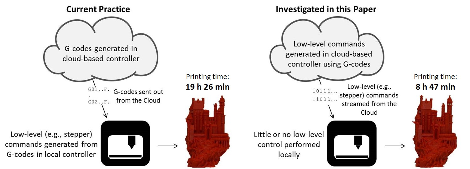
A wide range of 3D printing services (e.g., cloud-based part modeling, slicing and printing services) rely on cloud computing and SOAs [23,24]. Most relevant to CaaS is the growing trend to control 3D printers remotely via web-based wireless host platforms like 3DPrinterOS [25], Astroprint [26], OctoPrint [27], and Repetier Server [28]. However, as shown in Figure 1a, these platforms control 3D printers by sending out G-codes (or equivalent high-level control commands) from the Cloud to the printers, while assigning the low-level computations to a local controller (e.g., a microcontroller). Therefore, such wireless host platforms do not offer CaaS, at least not in the context discussed in this paper.
Cloud-based control in the context of CaaS seeks to perform low-level computations for real-time control of a device in the Cloud, instead of on a local controller [1,2,3,4,5,6,7,8,9,10,11,12,13,14,15,16]. In the specific case of 3D printers, this implies that stepper motor commands (or similar low-level signals) are computed in and sent out from the cloud-based controller, as opposed to G-codes (see Figure 1b). Accordingly, low-level control of the device can be realized using advanced algorithms which may not be executable on a local controller with limited computational resources. Control as a Service thus holds the potential to significantly improve the performance of devices without need for powerful (and often costly) computational hardware. Also, with CaaS, upgrading the control system of a device becomes much easier, as significant hardware changes need not be made locally. This reduces the problem of frequent obsolescence of devices due to outdated control boards that cannot support new, more capable, control algorithms. The connected infrastructure provided by CaaS also allows cloud-based control algorithms to benefit from data sharing. For instance, artificial intelligence and big data analytics could be used to improve the performance of control algorithms (e.g., optimize control parameters) based on feedback from several devices running the algorithms. Moreover, in CaaS, a variety of control algorithms could be offered in an “app marketplace”, where they are accessed if and when needed by a given device. For more details on the various benefits of CaaS, see [1,2,3,4,5,6,7,8,9,10,11,12,13,14,15,16].
However, for CaaS to achieve low-level control of devices directly from the Cloud, delays, dropped packets, and other quality-of-service (QoS) issues that inhibit real-time communication over the Internet must be adequately mitigated. Several preliminary studies have been conducted to test the feasibility of cloud-based real-time control of devices, and approaches to mitigate QoS issues. One of the earliest works in this regard was that by Givehchi et al. [3] who made a case for cloud-based programmable logic controllers (PLCs) in industrial automation. Their results showed lower performance using the cloud-based PLC compared to a local PLC, due to network-induced delays, particularly as real-time computation demands became more stringent. Similar conclusions have been reached by Hegazy and Hefeeda [4], Esen et al. [5], Kaneko and Ito [9], Vick et al. [10], Abdelaal et al. [14], and Mubeen et al. [15] in their tests of cloud-based controllers on various real-time control applications. Solutions proposed to counter the effects of delays and other QoS issues in CaaS include implementation of real-time controllers using private clouds [11] or in the Fog [15], both involving the use of local area networks (LANs) as opposed to wide area networks (WANs) to reduce delays. Other solutions involve the use of redundant control architectures [4,9,16] and various forms of delay compensation techniques [4,5,10,14,15,16]. The solutions to QoS issues presented in the discussed preliminary studies have yielded encouraging results: they have generally demonstrated that, with proper mitigation of QoS issues, cloud-based controllers can approach the performance of equivalent local controllers. However, the aspiration of CaaS is for cloud-based controllers to surpass the performance of local controllers by running superior control algorithms and exploiting other advanced functionalities available in the Cloud.
3D printers are an excellent case study for advancing CaaS, especially since many of them (particularly those of the desktop kind) have very limited computational resources on their local controllers. The control performance of desktop 3D printers could be significantly improved at low cost via cloud-based control algorithms provisioned through CaaS. Industrial-grade 3D printers could also benefit significantly from advanced control algorithms that run physics-based models provisioned through CaaS; because even the high-end computational hardware available locally on industrial-grade 3D printers often cannot execute computationally-intensive physics-based models. Moreover, critical aspects of 3D printer control (e.g., motion control) are typically open-loop, making them an excellent beachhead for CaaS, from an application standpoint, since most deleterious effects of network delays are associated with closed-loop control. Lastly, the open innovation and maker disposition of significant segments of the 3D printing ecosystem [23] is a boon for CaaS (e.g., by facilitating data sharing and the co-creation of a variety of cloud-based “control apps”). However, to the authors’ knowledge, the feasibility, unique benefits and challenges of CaaS have not been explicitly explored in the context of 3D printing.
Therefore, this paper presents preliminary work on low-level motion control of a desktop 3D printer from the Cloud, as a first step towards in-depth research into 3D printer CaaS (3DPCaaS). It not only shows that low-level control of 3D printers from the Cloud is feasible, but also demonstrates huge improvements in 3D printing speed and accuracy that can be achieved using an advanced cloud-based motion controller over a standard local controller. Section 2 presents the experimental setup used for the study, and describes the software and hardware implementation of the cloud-based and local controllers. Section 3 then presents the results of various prints using the cloud-based controller running an advanced motion control algorithm, benchmarked against prints made using a standard local controller. This is followed by discussions, conclusions, and future work.
2. Materials and Methods
The experimental setup is shown in Figure 2. It consists of a Wi-Fi-enabled laptop PC, the Google Cloud Platform, an ESP32 Wi-Fi board connected to four DRV8825 stepper drivers which are used to separately drive the X-, Y-, and Z-axes and E (extruder) motors of a Lulzbot Taz 6 desktop 3D printer. Details of each component are described in the following subsections.
2.1. Laptop PC
The laptop PC provides the user interface for interacting with the printer. It runs a secure shell (SSH) terminal on a Linux operating system. The SSH terminal allows a user on the laptop to login remotely to an SSH server on the Google Cloud Platform using the Internet’s transmission control protocol (TCP). Once logged in, the user can upload the G-code file for the part to be printed, as well as parameters needed to run the cloud-based advanced controller. Through the SSH terminal, the user can also input five high-level motion control commands into a code responsible for sending the commands to the ESP32 board via TCP. The five commands are:
- ‘init’: Initialize communications by confirming that a connection has been established between the Google Cloud Platform and the ESP32 board;
- ‘jog <x/y/z/e> <+/−><counts>’: Jog the specified axis in the specified direction by the specified number of stepper motor counts;
- ‘start’: Start the transmission of stepper motor signals from the Google Cloud Platform to the ESP32 board;
- ‘stop’: Stop the transmission of stepper motor signals from the Google Cloud Platform to the ESP32 board;
- ‘exit’: End the connection between the Google Cloud Platform and the ESP32 board.
2.2. Google Cloud Platform
The Google Cloud Platform [29] is a suite of cloud computing services offered by Google. The services include computation, data storage, data analytics, and machine learning. We specifically make use of the Google Compute Engine which allows users to, on demand, run computations on cloud computers (i.e., virtual machines (VMs)), which are emulations of computer systems running on dedicated servers. The user can select the geographical location (i.e., region and zone) of the VM they would like to utilize; and, at variable prices, they can also configure the hardware and operating system of the VM of choice. For our experiments, we used the free one-year subscription available on the Google Cloud Platform.
Figure 3 gives an overview of the advanced motion controller running on the Google Cloud Platform. It consists of the following algorithms, all programmed in Python.
- A jerk-limited motion command generator [30] (i.e., S-curve speed profile) which reads in the X and Y positions and feedrates from a G-code file and plans motion trajectories along the X and Y directions in such a way that user-specified acceleration and jerk limits are adhered to. It also reads in the Z and E commands from the G-code file and generates Z and E motion trajectories without considering any limits on acceleration and jerk (i.e., infinite acceleration and jerk are assumed because of the low feedrates of Z and E motions). The outputs of the motion generator are X, Y, Z, and E motion commands (double-precision floating point format), outputted non-real-time at 1 ms time intervals (1 kHz sampling frequency).
- The limited-preview filtered B-spline (LPFBS) algorithm [31]: It converts the X and Y commands outputted from the motion command generator to modified commands (denoted as X′ and Y′, respectively) that minimize the vibration of the printer, based on measured and modeled frequency response functions (FRFs) of the printer’s dynamics; please refer to Reference [31] for more details. The LPFBS algorithm is too computationally intensive to run on the ATMega2560 microcontroller available on the Taz 6 3D printer. It is the main reason for considering a cloud-based controller for the printer. Note that the LPFBS algorithm does not modify the Z and E commands because their motions do not cause significant vibration.
- Stepper motor command generator: It takes the double-precision floating point X′, Y′, Z and E commands at 1 kHz sampling frequency and converts them to step and direction signals for the corresponding stepper motors at 20 kHz stepping frequency. The conversion process is fairly standard. The signals are first up-sampled from 1 to 20 kHz via linear interpolation, and then quantized into discrete steps at integer multiples of the stepper motor resolution, which is 101.5 steps/mm for the X and Y motors, 1600 steps/mm for the Z motor and 760 steps/mm for the E motor.
- UDP packetization and sequencing: There are two standard protocols for transmitting data over the Internet—the TCP and the user datagram protocol (UDP). Transmission control protocol is a very reliable connection which guarantees that the transmitted data is not scrambled (re-ordered) or lost; UDP provides no such guarantees. However, TCP typically introduces significantly longer delays in transmission than UDP [13]. As a delay mitigation technique, we choose to transmit the stepper motor signals over a UDP connection. To ensure the correct ordering and completeness of the transmitted signals, the packetization and sequencing algorithm places a series of X′, Y′, Z and E step and direction commands into a packet in chronological order. Each packet is at most 1420 bytes in size to ensure that it is below the 1500-byte maximum transfer unit for packets transported over the Internet using an Ethernet frame, thereby preventing internet protocol packet fragmentization. In addition to the step and direction signals, each packet contains a packet number and other ancillary data. The packet number is used to ensure the reception of each UDP packet (via an acknowledgement signal sent out from the ESP32 board) as well as to re-order the packets in chronological sequence after they are received. Each 1420-byte packet contains about 1200 bytes of stepper motion commands at 1 byte/step (for the four motors combined) at 20,000 steps/s. Therefore, an average transmission rate of at least 189 kbps is required for the UDP connection to maintain uninterrupted transmission of the stepper motor commands.
Notice from Figure 3 that while the UDP packets are sent to the ESP32 board via UDP connection, the high-level commands are sent via TCP connection, since their execution is not as time-critical as the stepper motion signals.
2.3. ESP32 Wi-Fi Board and DRV8825 Stepper Drivers
The ESP32-DEVKITC V4 CE FCC Rev 1 Silicon development board was used. It is equipped with Wi-Fi (up to 150 Mbps), Bluetooth, a dual-core 32-bit LX 6 microprocessor running at 240 MHz with 520 KB of static random-access memory (SRAM) among other features. In our experiments, the ESP32 board was used primarily to: receive the signals transmitted from the Cloud via Wi-Fi; perform very basic processing to ensure the correct sequencing of the UDP packets; request for any lost packets; and parse and execute the received high-level commands and stepper motion commands by sending them out to four DRV8825 stepper drivers connected (wired) to the X, Y, Z and E motors of the Taz 6 printer. Figure 4 gives an overview of the functionalities (firmware) coded into the ESP32 board in C++. They are:
- Re-sequencing and completeness check: This algorithm gathers the received UDP packets in batches of ten and orders the packets according to their packet numbers. An acknowledgement signal is sent to the cloud-based controller indicating all packets that were received. Any packets that were not received are re-transmitted, and transmission of the next batch of ten packets from the Cloud is halted until the missing packets from the previous batch are received.
- FIFO buffering and signal extraction: The received and ordered packets are placed in a first-in first-out (FIFO) buffer which can hold up to 100 packets at any given time; it is size-limited by the SRAM of the ESP32. The buffer is filled up before printing starts, providing a six-second time buffer in case of delays. The printing is paused if the buffer is emptied. The step and direction signals from the packets stored in the buffer are extracted and sent to the stepper drivers in real-time at 20 kHz stepping frequency.
- Execution of high-level commands: The high-level commands are executed in the ESP32, as described in Section 2.1. For the jog command, the step and direction commands are extracted and sent to the corresponding stepper drivers to move the machine as commanded.
2.4. Lulzbot Taz 6 Desktop 3D Printer
A Lulzbot Taz 6 printer with dual extruders was used for the experiments. It comes with a local controller in the form of the Marlin firmware (for TAZ6 Dual Extruder 3 v1.1.5.71) running on a RepRap Arduino-compatible Mother Board (RAMBo). The RAMBo uses the ATMega2560 chip, having an 8-bit 16 MHz processor with 8 KB SRAM, which are too meager to execute the LPFBS algorithm. The RAMBo comes with its own Allegro 4892 stepper drivers which are used to control the stepper motors of the Taz 6 during printing with the local controller. When prints were performed with the cloud-based controller, the stepper drivers of the RAMBo board were disconnected, and the DRV8825 stepper drivers were wired to the printer’s stepper motors. Note, however, that when using the cloud-based controller, the RAMBo board was still connected to the printer and provided all other low-level control functionalities (besides stepper motor control) like nozzle and heat bed temperature control. These low-level control functionalities could certainly be moved to the cloud-based controller, but for the purposes of this preliminary study focused on motion control, they were retained in the local controller.
3. Results
Two sets of experiments were conducted. The goal of the first set of experiments was to calibrate key parameters of algorithms running on the local controller (Marlin) and cloud-based controller. The second set of experiments was conducted to evaluate the performance of the cloud-based controller (in comparison with that of the local controller) using the parameters determined from the first set of experiments.
3.1. Calibration Experiments
The local controller (Marlin) runs a trapezoidal-speed motion command generator, which allows for limited-acceleration but infinite-jerk motion commands. In addition, it has a parameter known as jerk speed, which is a speed threshold below which motion commands are generated with infinite acceleration. A common practice is to tune the acceleration limit and jerk speed values iteratively to obtain the highest values that do not lead to excessive vibration of a given 3D printer. This allows the printer to travel as fast as possible while maintaining acceptable print surface quality (i.e., surfaces with minimal vibration marks, also known as ringing).
A very common artifact used for determining acceptable acceleration and jerk speed limits on desktop 3D printers like the Lulzbot Taz 6 is the XYZ Calibration Cube (with 20 mm sides), shown in Figure 5. The sudden changes of motion direction at the edges of the cube and at the X and Y imprints on the faces of the cube excite vibration along the X and Y axes of the printer, leading to ringing on the faces of the cube. Table 1 provides the key parameters used in all tests presented in this paper for slicing the calibration cube in Cura (Lulzbot Edition 21.04).
The first rows of Table 2 and Table 3 respectively show the X and Y faces of the Calibration Cube printed using the local controller (i.e., Marlin running on the RAMBo board). Note that the cube is arbitrarily printed with its X-face aligned with the Y-axis, and is Y-face aligned with the X-axis of the Taz 6. All prints using the local controller are made with the default jerk speed of the Taz 6 printer (i.e., 10 mm/s). Notice that with the default acceleration limit of the printer (i.e., 0.5 m/s2), the quality of the faces is generally okay, though each face has some ringing, with the X-face exhibiting a bit more ringing than the Y-face. As the acceleration limits are raised to 1, 5, and 10 m/s2, the ringing steadily intensifies leading to increasingly worse surface quality, even though printing time progressively decreases.
The cloud-based controller has two algorithms which together help to reduce vibration. First it uses a jerk-limited motion command generation (JLMCG) algorithm (also known as S-curve speed profile) [30] which allows limitations on both acceleration and jerk. Moreover, it adds on the limited-preview filtered B-spline (LPFBS) algorithm [31] which modifies motion commands to minimize vibration based on measured vibration dynamics of the printer. For the sake of the calibration tests, both algorithms (together with the stepper motor command generator in Figure 3) are implemented on the dSPACE DS1007 real-time control board running at 40 kHz clock frequency. The step and direction signals are sent via a wired connection at 13.33 kHz frequency to four DRV8825 stepper drivers connected to the X, Y, Z and E motors of the Taz 6 printer. In other words, the algorithms are implemented locally on a high-end motion control board with sufficient computational resources to run the LPFBS algorithm.
The second rows of Table 2 and Table 3, respectively, show the effects of JLMCG on the X- and Y-faces of the calibration cube. The jerk limit is set at 5000 m/s3, and acceleration limits of 0.5, 1, 5, and 10 m/s2 are tested. Notice the improvements in surface quality compared to the local controller, though at the expense of longer printing time in each case due to the fact that both acceleration and jerk were limited.
To execute the LPFBS algorithm, the vibration dynamics of Taz 6 must be measured in the form of frequency response functions (FRFs) and modeled mathematically (see Reference [31] for details). Figure 6 shows the measured and modeled FRFs of the X- and Y-axes of the Taz 6; the input of each FRF was acceleration commands to the corresponding stepper motor, and the output was relative acceleration between the build plate and nozzle in that direction, measured using accelerometers. The resulting transfer functions of the X and Y axes are given by Equations (1) and (2), respectively.
The slight discrepancies seen in Figure 6 between the measured and modeled (curve fit) FRFs at low and high frequencies are due to the fact that the fitting is weighted to more accurately match dynamics around the resonance peaks, at the expense of dynamics at lower and higher frequencies. This is because the dynamics around the resonance frequencies are most influential on the vibration of the printer.
Table 4 summarizes other key parameters needed for implementing the LPFBS algorithm, following the detailed description and the exact same notations as used in Reference [31]. The third rows of Table 2 and Table 3 respectively show the effects of JLMCG and LPFBS on the X and Y-faces of the Calibration Cube. Notice the significant improvements in surface quality at each acceleration level (without increasing the printing time relative to those of JLMCG alone).
Looking at the X-face of the cube, which is generally worse than the Y-face in terms of vibration marks, the quality of the 10 m/s2 case of JLMCG and LPFBS is at least as good as, if not better than, that of the local controller at its default 0.5 m/s2 acceleration limit. Therefore, in the following experiments, an acceleration limit of 0.5 m/s2 and jerk speed of 10 mm/s were used for the local controller while an acceleration limit of 10 m/s2 and jerk limit of 5000 m/s3 were used for the cloud-based controller (which runs both JLMCG and LPFBS).
3.2. Comparison of Local Controller with Cloud-Based Controller
Using the results of the calibration performed in the preceding section, two parts are printed using the cloud-based controller and compared with the same parts printed using the local controller (Marlin). The cloud-based controller was run on Google Compute Engines in two geographical locations—Moncks Corner, South Carolina and Sydney, Australia. Table 5 provides specifications of the VMs at each location. The first location was selected to be sufficiently close to Michigan, where the printer was located, while the second location was selected to be as far as possible away from Michigan.
The first part printed was the Calibration Cube of Figure 5. Four samples of the cube were printed from each location. Table 6 and Table 7 compare key attributes of the prints from the South Carolina and Australia-based controllers, respectively. For all four trials, the South Carolina-based controller ran hitch free, without any pauses due to latency. As a result, it returned prints with consistent printing times and similar surface quality as the corresponding part printed using dSPACE. Interestingly, the printing times of the South Carolina-based controller are about one minute shorter than that from dSPACE (see Table 2 and Table 3). This is due to slight differences in the implementation of the algorithms on dSPACE and the VMs. The dSPACE is a real-time computer which was run at a fixed 40 kHz clock frequency. The clock frequency was down-sampled by a factor of three to create each step for the stepper motors in real time at 13.33 kHz, and by a factor of 40 to generate the outputs of the JLMCG and LPFBS algorithms in real time at 1 kHz. On the other hand, the VMs are non-real-time computers. They ran the JLMCG and LPFBS algorithms at a sampling frequency of 1 kHz (non-real-time) and then up-sampled the output to 20 kHz stepping frequency. The non-real-time nature of the VMs provides more flexibility in the implementation of the algorithms (allowing up-sampling rather than down-sampling), leading to fewer approximations hence reductions in printing time.
A bit different from the South Carolina-based controller, the Australia-based controller experienced two short pauses due to internet delays during the first trial print, but the other three trials ran hitch free. As a result, the printing time for time for first trial was 19 s longer than those of the other three trials. However, the pauses did not have any noticeable effect on the surface quality of the first trial part. During each print, the round-trip time (RTT) was logged at regular intervals. The RTT measures the duration between sending a signal via internet protocol and getting an acknowledgement of its reception, and is commonly used as a measure of internet transmission- induced delays. Notice that the average and maximum RTT were significantly higher for the Australia-based controller compared to the South Carolina-based controller, in large part due to the longer distances traveled by the signals. Moreover, the first trial on the Australia based controller exhibited slightly higher average RTT than the other three trials; its peak RTT was also slightly higher than the others, though trial 3 had the largest peak RTT.
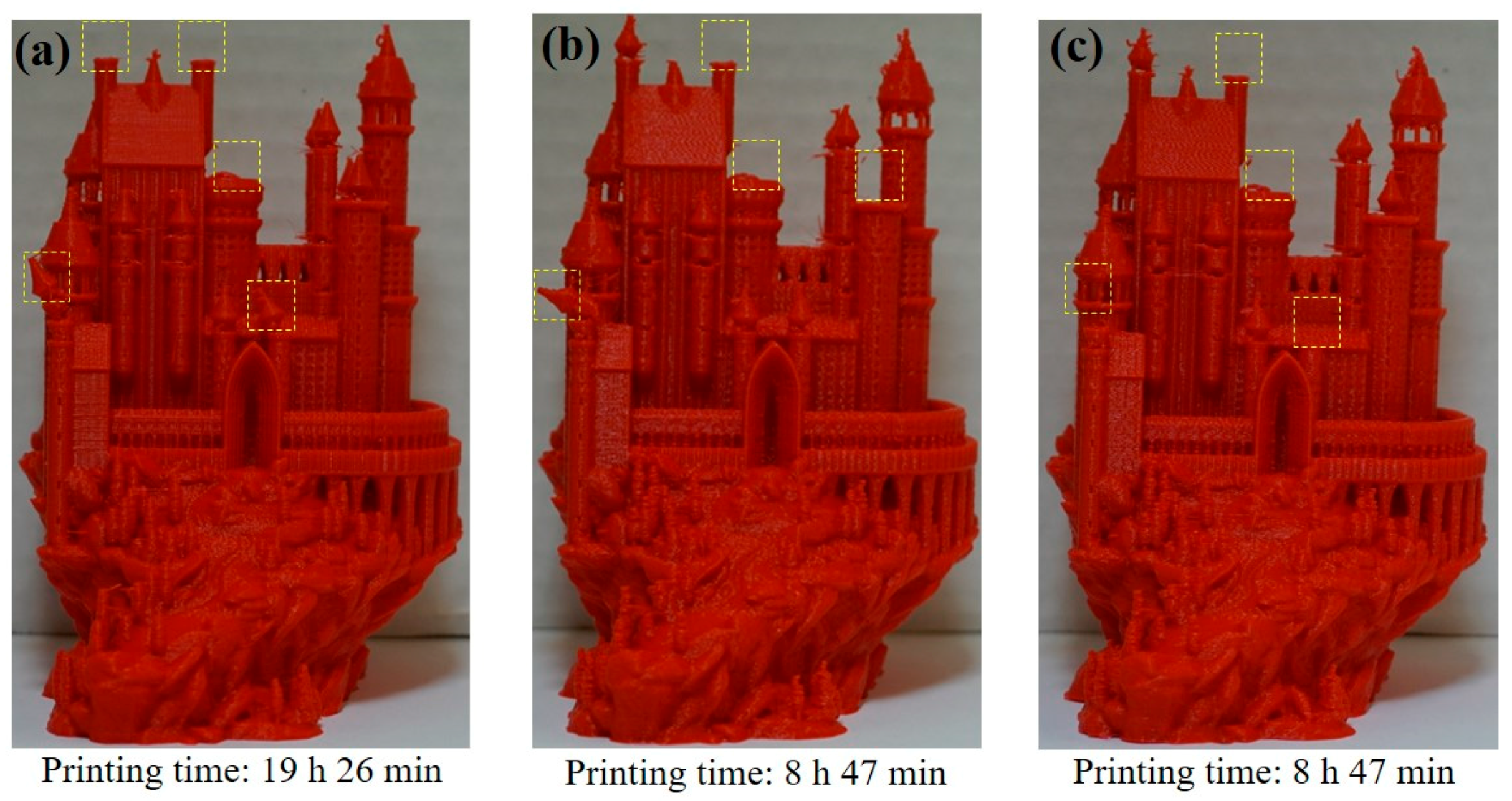
To compare the cloud-based controller to the local controller on a more involved print, the Medieval Castle model shown in Figure 7 was sliced in Cura using the parameters reported in Table 8. It was printed using the default parameters of the local controller (i.e., 0.5 m/s2 acceleration and 10 mm/s jerk speed), as well as using the cloud-based controller hosted in South Carolina and Australia with 10 m/s2 acceleration and 5000 m/s3 jerk limits. The results are shown in Figure 8. The local controller completed the print in 19 h 26 min while the cloud-based controller in South Carolina and Australia both completed it in 8 h 47 min, without any pauses throughout the prints. Note that the Castle could not be printed via dSPACE because of memory limitations; the G-code file for the Castle is 20 MB in size and could not be loaded into the memory of the dSPACE system for real-time execution. However, a PC-based MATLAB Simulink emulator, which predicts the printing time of the algorithms running on dSPACE accurately to the order of milliseconds, calculated a printing time of 9 h 27 min for the Castle. Therefore, the printing time of the cloud-based controller would have beaten that of the dSPACE system by 40 min (7%). Moreover, the memory limitations of the dSPACE system highlight the potential benefit of cloud-based controllers (whose memory requirements can be provisioned as need be).
In terms of printing accuracy, the prints by the local and cloud-based controllers are very similar. Notice that the local and cloud-based controllers alike failed in printing a few features at the top of some towers of the castle, highlighted by dashed yellow rectangles in Figure 8. Those features broke off during printing due to very delicate support structures, and may need to be printed at feedrates much lower than 75 mm/s on both the local and cloud-based controllers. However, printing just those delicate portions at lower feedrates is not likely to affect overall printing time very significantly.
4. Discussion, Conclusions, and Future Work
The results of this preliminary study demonstrate the technical feasibility of cloud-based control of 3D printers via low-level stepper motion commands, as opposed to high-level G-codes, streamed directly from the Cloud. In all but one of the prints performed via the cloud-based controller, no hang-ups were experienced due to excessive transmission delays. Moreover, the accuracy of the prints was not compromised, even for the one print that experienced a few hang-ups.
It is however important to note that the success of most of the prints in our preliminary tests does not mean that internet QoS is a non-issue for 3DPCaaS. Sometimes, QoS can degrade unexpectedly. In a test between a server in Germany and a client in New Zealand, Schlechtendahl et al. [13] observed average and peak RTT of about 300 ms and 20 s, respectively, using a UDP connection (and much longer delays using a TCP connection). Their 300 ms average RTT is very much in line with those observed in our experiments, but their 20 s peak RTT could definitely cause blobs like those shown on the Calibration Cube in Figure 9. The cube in Figure 9 was printed from a cloud-based controller on the f1-micro Google Compute Engine in Sydney, Australia, which has lower computational power than the n1-standard-1 Compute Engine used in our experiments (whose CPU always stayed below 50% utilization). As a result, the print would often pause not because of excessive internet transmission delays but because the Compute Engine could not execute the cloud-based algorithms fast enough, leading to extra molten filament oozing out while the print was paused to re-fill the buffer. Ongoing research at the Smart and Sustainable Automation (S2A) Lab at the University of Michigan is looking into delay mitigation techniques that minimize adverse effects on print quality and speed in the event of severe QoS issues in 3DPCaaS. One approach being studied is a hybrid architecture where a cloud-based controller works in concert with a local controller to ensure that printing is always hitch free, irrespective of the prevailing QoS. This idea is similar to “anytime” load balancing algorithms used in speech recognition on smart phones, where algorithms are run both on the Cloud and locally [20]. Methods for ensuring network security and privacy for 3DPCaaS are also being researched at the S2A Lab, in collaboration with computer scientists.
The results from this preliminary study also demonstrate the potential benefits of CaaS to 3D printing through access to advanced control algorithms which may not be executable on standard local controllers. Note that the benefits of the LPFBS algorithm in terms of improving 3D printing speeds and accuracy via vibration compensation have already been demonstrated in Reference [31]. However, in Reference [31], the LPFBS algorithm was implemented on a relatively expensive high-end control system (dSPACE DS1007). Efforts to execute it on the low-cost ATMega2560 chip, widely used on desktop 3D printer control boards, were not successful due to the algorithm’s high computational requirements. Therefore, for such 3D printers to run advanced algorithms like LPFBS, they would need significant hardware upgrades to more powerful microcontrollers (e.g., ARM Cortex-M4). Even then, there may be limitations on how many such advanced algorithms can be run on a given microcontroller.
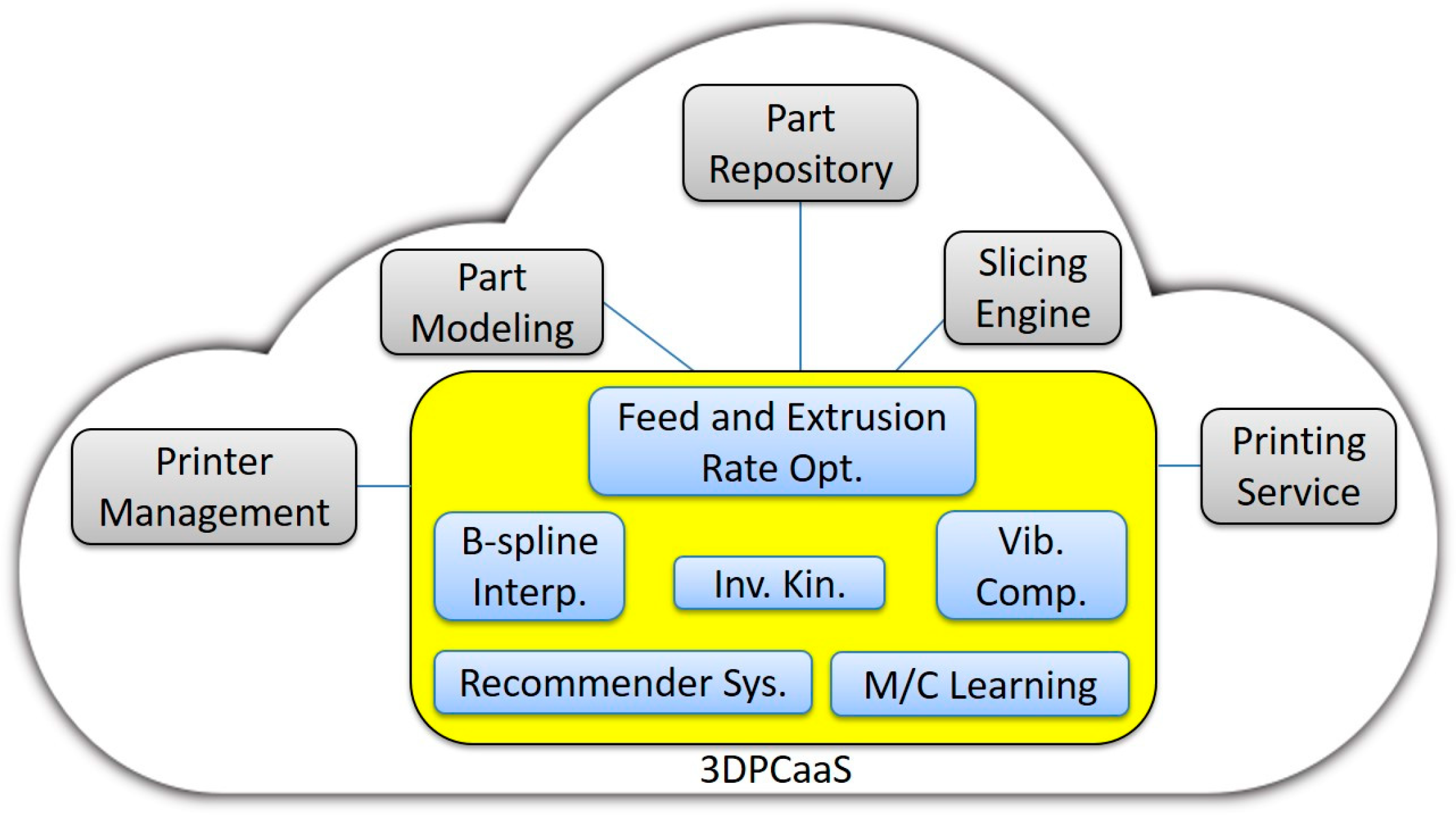
Control as a Service opens up a lot of exciting opportunities for 3D printing, as depicted in Figure 10. Wi-Fi enabled 3D printers can connect to cloud-based ecosystems comprising a variety of existing services [23,24] like part modeling, part slicing, part repositories, part printing, printer management, etc., all integrated with 3DPCaaS. A lot of synergies can be gained by having these services closely tied together with 3DPCaaS. For instance, G-codes, which have very poor representation of design intent, can be eliminated altogether. A cloud-based slicer can directly coordinate with the cloud-based controller to, for example, iteratively select an in-fill pattern that achieves the design intent while allowing the printer to run at maximum speed considering the printer’s dynamics. Smooth spline curves used to create part models in the Cloud can also be used for advanced spline interpolation in the cloud-based controller, instead of using G01 (short-line) approximations in G-code, thus yielding smoother and faster prints. 3D printers can have access to a menu of advanced controllers for B-spline interpolation, feed and extrusion rate optimization, inverse kinematics, vibration compensation, bed distortion compensation, etc., which they can deploy based on the requirements of the part to be printed. Through CaaS, a recommender system can be provisioned that uses crowd sourcing of user feedback to recommend control algorithms for a particular printer and print job. Machine learning can be used to perform analytics to help optimize the performance of the control algorithms (e.g., fine-tune their parameters) based on a global view of the interaction of each algorithm with all the printers connected to the Cloud. And the list goes on. Future work at the S2A Lab will focus on researching and developing various kinds of algorithms and advanced functionalities that can be provisioned through 3DPCaaS, and bringing them to the attention of the 3D printing community. Interested readers can join in or follow updates on this research at www.3DPCaaS.org.
Author Contributions
C.E.O. was responsible for conceptualization, funding acquisition, project administration, supervision, methodology, visualization, and all writing. S.H. and S.S. were responsible for software, methodology, and validation. C.H. and B.Z. were responsible for investigation and validation.
Funding
This work was funded by discretionary research funds from the University of Michigan.
Acknowledgments
The authors would like to thank: Deokkyun Yoon for providing feedback and support on the implementation of the LPFBS algorithm; Harsha Madhyastha for feedback on internet protocols; Andrew Edoimioya and Oluwami Dosunmu-Ogunbi for help with literature review on CaaS; and Aleph Objects, Inc. for donating the Lulzbot Taz 6 printer used in this study.
Conflicts of Interest
The authors declare no conflict of interest. The funders had no role in the design of the study; in the collection, analyses, or interpretation of data; in the writing of the manuscript, and in the decision to publish the result.
References
- Givehchi, O.; Trsek, H.; Jasperneite, J. Cloud computing for industrial automation systems—A comprehensive overview. In Proceedings of the 2013 IEEE 18th Conference on Emerging Technologies & Factory Automation (ETFA), Cagliari, Italy, 10–13 September 2013; pp. 1–4. [Google Scholar]
- Verl, A.; Lechler, A.; Wesner, S.; Kirstädter, A.; Schlechtendahl, J.; Schubert, L.; Meier, S. An approach for a cloud-based machine tool control. Procedia CIRP 2013, 7, 682–687. [Google Scholar] [CrossRef]
- Givehchi, O.; Imtiaz, J.; Trsek, H.; Jasperneite, J. Control-as-a-service from the cloud: A case study for using virtualized PLCs. In Proceedings of the 2014 IEEE 10th Workshop on Factory Communication Systems (WFCS), Toulouse, France, 5–7 May 2014; pp. 1–4. [Google Scholar]
- Hegazy, T.; Hefeeda, M. Industrial automation as a cloud service. IEEE Trans. Parallel Distrib. Syst. 2015, 26, 2750–2763. [Google Scholar] [CrossRef]
- Esen, H.; Adachi, M.; Bernardini, D.; Bemporad, A.; Rost, D.; Knodel, J. Control as a service (CaaS): Cloud-based software architecture for automotive control applications. In Proceedings of the Second International Workshop on the Swarm at the Edge of the Cloud, Seattle, WA, USA, 13–16 April 2015; pp. 13–18. [Google Scholar]
- Vick, A.; Horn, C.; Rudorfer, M.; Krüger, J. Control of robots and machine tools with an extended factory cloud. In Proceedings of the 2015 IEEE World Conference on Factory Communication Systems (WFCS), Palma de Mallorca, Spain, 27–29 May 2015; pp. 1–4. [Google Scholar]
- Vick, A.; Vonásek, V.; Pěnička, R.; Krüger, J. Robot control as a service—Towards cloud-based motion planning and control for industrial robots. In Proceedings of the 2015 10th International Workshop on Robot Motion and Control (RoMoCo), Poznań, Poland, 6–8 July 2015; pp. 33–39. [Google Scholar]
- Hallmans, D.; Sandström, K.; Nolte, T.; Larsson, S. Challenges and opportunities when introducing cloud computing into embedded systems. In Proceedings of the 2015 IEEE 13th International Conference on Industrial Informatics (INDIN), Cambridge, UK, 22–24 July 2015; pp. 454–459. [Google Scholar]
- Kaneko, Y.; Ito, T. A Reliable Cloud-Based Feedback Control System. In Proceedings of the 2016 IEEE 9th International Conference on Cloud Computing (CLOUD), San Francisco, CA, USA, 27 June–2 July 2016; pp. 880–883. [Google Scholar]
- Vick, A.; Guhl, J.; Krüger, J. Model predictive control as a service—Concept and architecture for use in cloud-based robot control. In Proceedings of the 2016 21st International Conference on Methods and Models in Automation and Robotics (MMAR), Miedzyzdroje, Poland, 29 August–1 September 2016; pp. 607–612. [Google Scholar]
- Horn, C.; Krüger, J. Feasibility of connecting machinery and robots to industrial control services in the cloud. In Proceedings of the 2016 IEEE 21st International Conference on Emerging Technologies and Factory Automation (ETFA), Berlin, Germany, 6–9 September 2016; pp. 1–4. [Google Scholar]
- Krüger, J.; Wang, L.; Verl, A.; Bauernhansl, T.; Carpanzano, E.; Makris, S.; Fleischer, J.; Reinhart, G.; Franke, J.; Pellegrinelli, S. Innovative control of assembly systems and lines. CIRP Ann. 2017, 66, 707–730. [Google Scholar] [CrossRef]
- Schlechtendahl, J.; Kretschmer, F.; Sang, Z.; Lechler, A.; Xu, X. Extended study of network capability for cloud based control systems. Robot. Comput. Integr. Manuf. 2017, 43, 89–95. [Google Scholar] [CrossRef]
- Abdelaal, A.E.; Hegazy, T.; Hefeeda, M. Event-based control as a cloud service. In Proceedings of the 2017 American Control Conference (ACC), Seattle, WA, USA, 24–26 May 2017; pp. 1017–1023. [Google Scholar]
- Mubeen, S.; Nikolaidis, P.; Didic, A.; Pei-Breivold, H.; Sandström, K.; Behnam, M. Delay mitigation in offloaded cloud controllers in industrial IoT. IEEE Access 2017, 5, 4418–4430. [Google Scholar] [CrossRef]
- Sang, Z.; Xu, X. The framework of a cloud-based CNC system. Procedia CIRP 2017, 63, 82–88. [Google Scholar] [CrossRef]
- Li, B.H.; Zhang, L.; Wang, S.L.; Tao, F.; Cao, J.W.; Jiang, X.D.; Song, X.; Chai, X.D. Cloud manufacturing: A new service-oriented networked manufacturing model. Comput. Integr. Manuf. Syst. 2010, 16, 1–7. [Google Scholar]
- Xu, X. From cloud computing to cloud manufacturing. Robot. Comput. Integr. Manuf. 2012, 28, 75–86. [Google Scholar] [CrossRef]
- Kuffner, J. Cloud-enabled robots. In Proceedings of the 2010 10th IEEE-RAS International Conference on Humanoid Robots (Humanoids 2010), Nashville, TN, USA, 6–8 December 2010. [Google Scholar]
- Kehoe, B.; Patil, S.; Abbeel, P.; Goldberg, K. A survey of research on cloud robotics and automation. IEEE Trans. Autom. Sci. Eng. 2015, 12, 398–409. [Google Scholar] [CrossRef]
- Armbrust, M.; Fox, A.; Griffith, R.; Joseph, A.D.; Katz, R.; Konwinski, A.; Lee, G.; Patterson, D.; Rabkin, A.; Stoica, I.; et al. A view of cloud computing. Commun. ACM 2010, 53, 50–58. [Google Scholar] [CrossRef]
- Erl, T. Service-Oriented Architecture; Prentice Hall: Upper Saddle River, NJ, USA, 2005; Volume 8. [Google Scholar]
- Rayna, T.; Striukova, L.; Darlington, J. Co-creation and user innovation: The role of online 3D printing platforms. J. Eng. Technol. Manag. 2015, 37, 90–102. [Google Scholar] [CrossRef]
- Baumann, F.W.; Roller, D. Additive Manufacturing, Cloud-Based 3D Printing and Associated Services—Overview. J. Manuf. Mater. Process. 2017, 1, 15. [Google Scholar] [CrossRef]
- 3DPrinterOS. Available online: https://www.3dprinteros.com/ (accessed on 8 August 2018).
- Astroprint. Available online: https://www.astroprint.com/ (accessed on 8 August 2018).
- OctoPrint.org. Available online: https://octoprint.org/ (accessed on 8 August 2018).
- Repetier Server. Available online: https://www.repetier-server.com/ (accessed on 8 August 2018).
- Google Cloud. Available online: https://cloud.google.com/ (accessed on 8 August 2018).
- Erkorkmaz, K.; Altintas, Y. High speed CNC system design. Part I: Jerk limited trajectory generation and quintic spline interpolation. Int. J. Mach. Tools Manuf. 2001, 41, 1323–1345. [Google Scholar] [CrossRef]
- Duan, M.; Yoon, D.; Okwudire, C.E. A limited-preview filtered B-spline approach to tracking control—With application to vibration-induced error compensation of a 3D printer. Mechatronics 2017. [Google Scholar] [CrossRef]
Figure 1.
(a) Current control of 3D printers from the Cloud using G-codes (e.g., as employed in printer management and web-based wireless host platforms); (b) Proposed low-level control of 3D printers from the Cloud intended for 3D printer Control as a Service (3DPCaaS).
Figure 1.
(a) Current control of 3D printers from the Cloud using G-codes (e.g., as employed in printer management and web-based wireless host platforms); (b) Proposed low-level control of 3D printers from the Cloud intended for 3D printer Control as a Service (3DPCaaS).
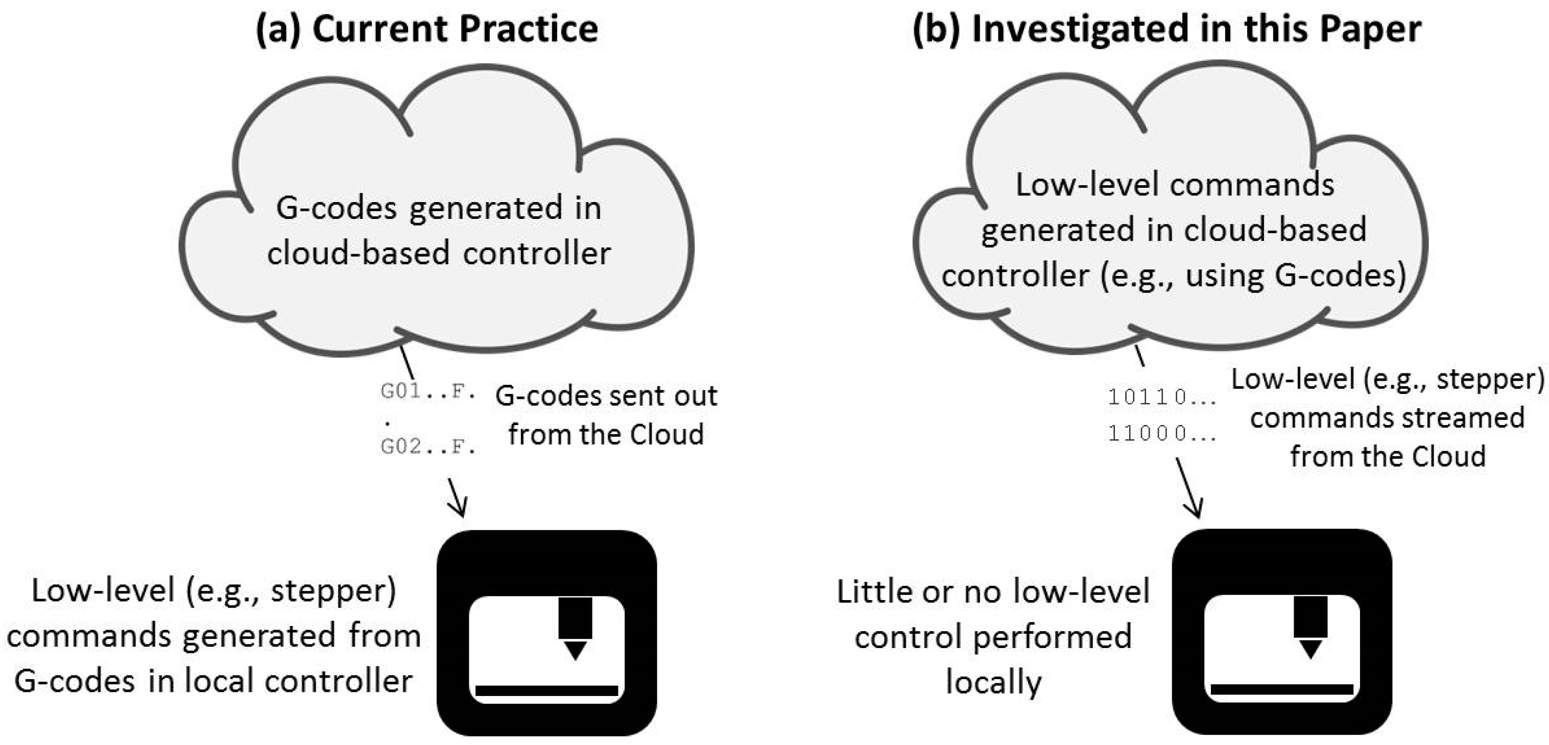
Figure 2.
Overview of setup for experiments.
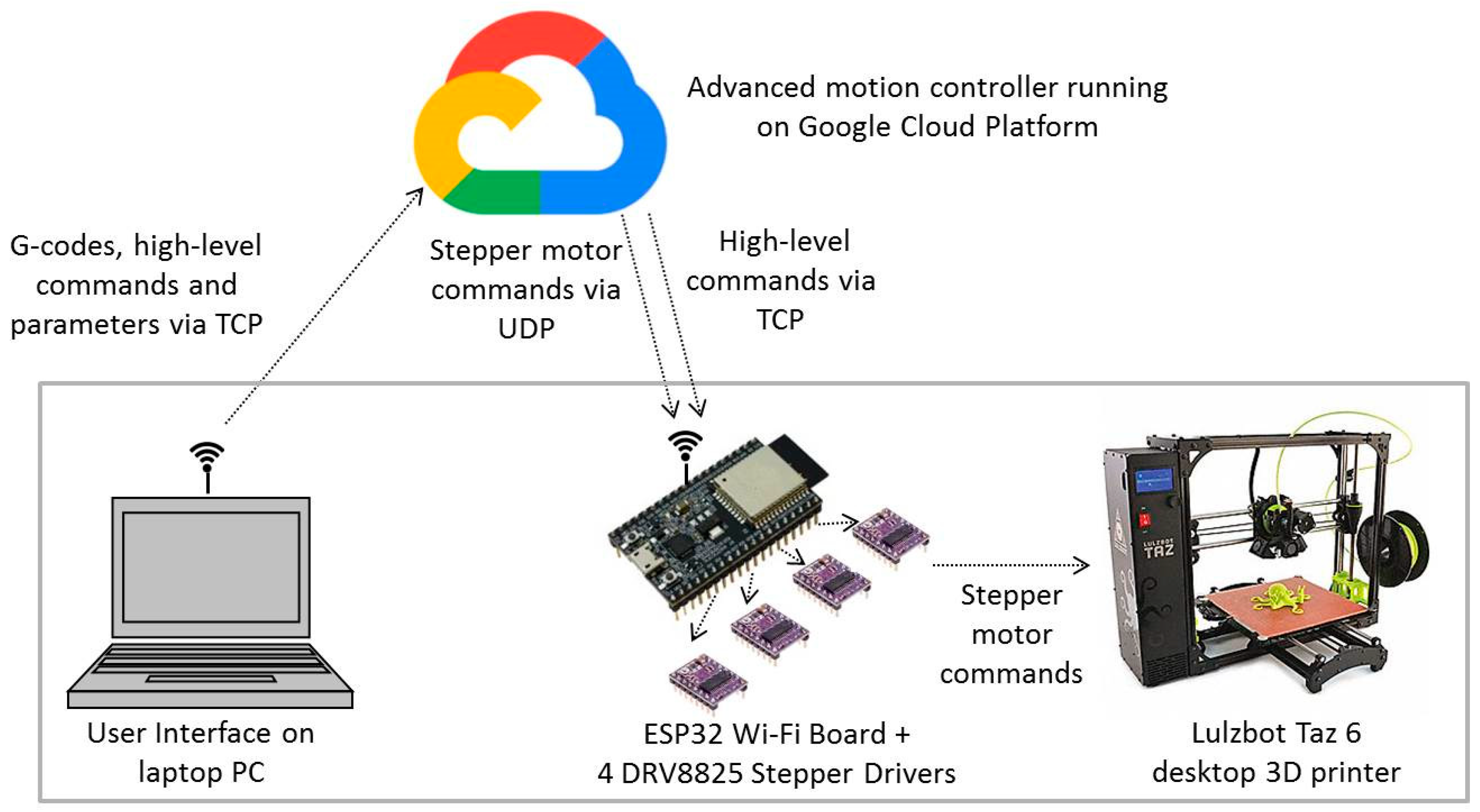
Figure 3.
Block diagram of algorithms contained in cloud-based controller running on the Google Cloud Platform. Note that the 1 and 20 kHz frequencies are not real-time execution rates, they represent the sampling frequencies of the output signals. The algorithm highlighted in red is a computationally intensive advanced algorithm for vibration compensation.
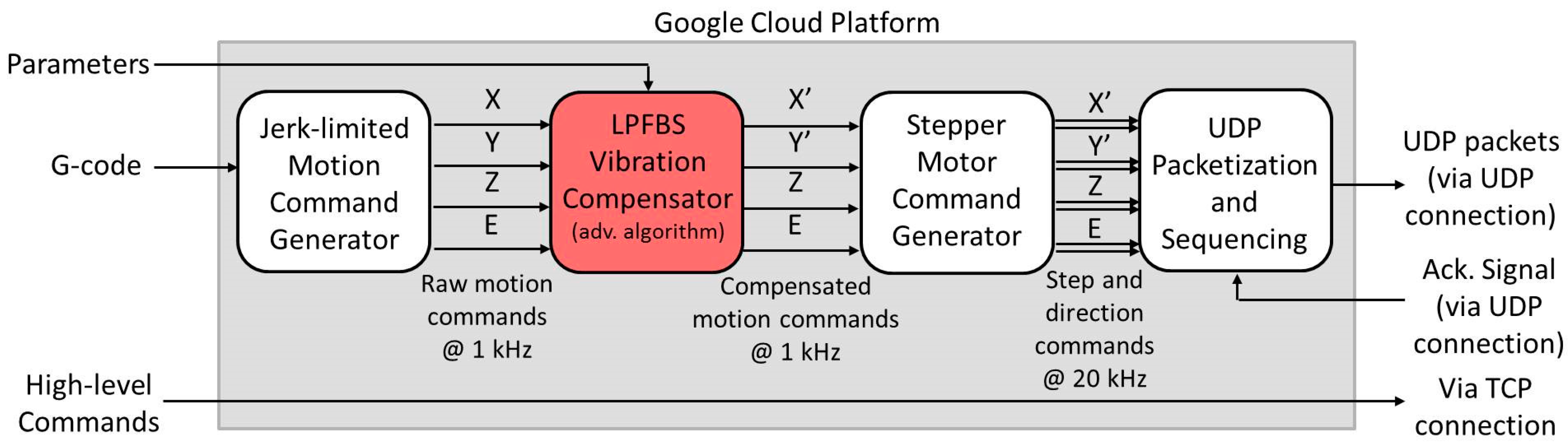
Figure 4.
Block diagram of functionalities coded as firmware into the ESP32 board.
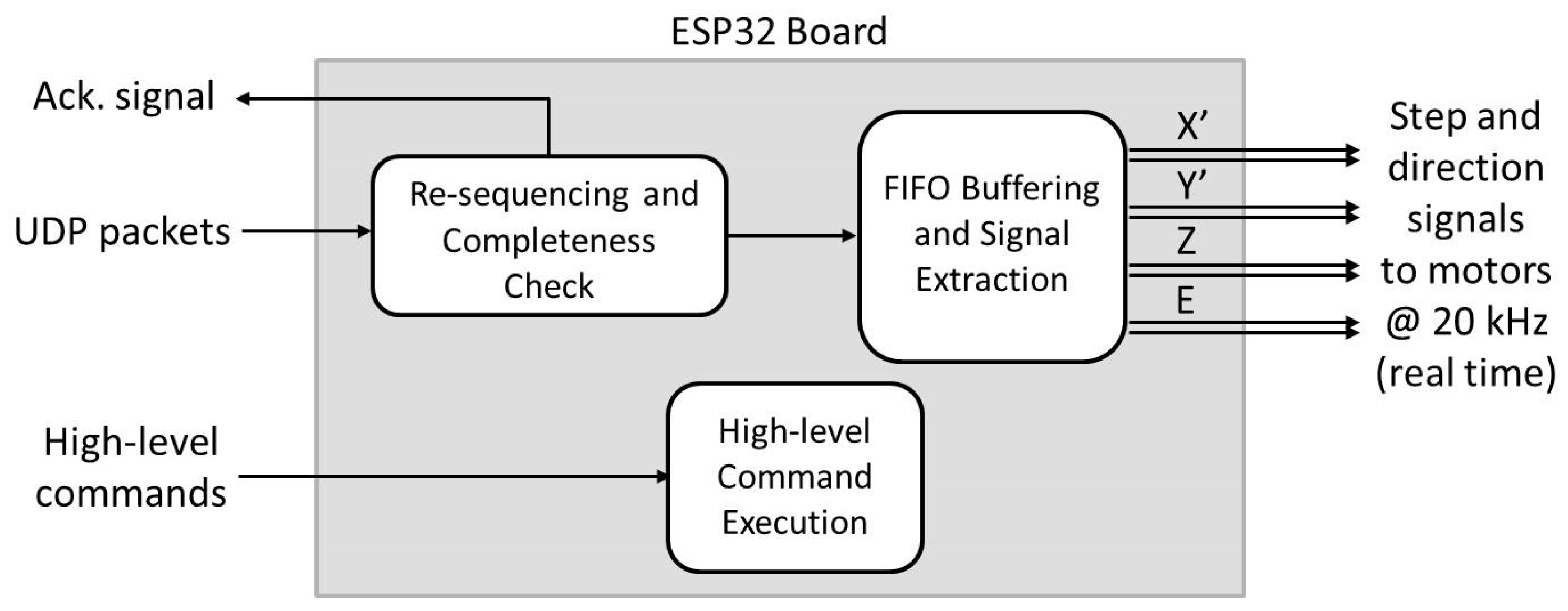
Figure 5.
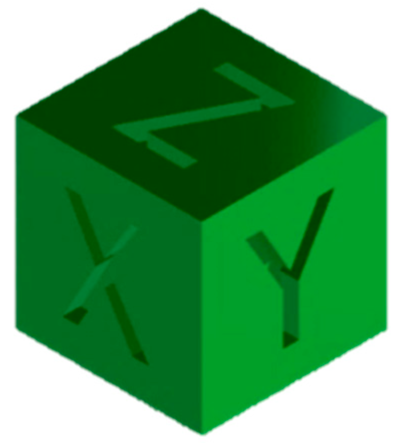
Computer aided design (CAD) model of XYZ Calibration Cube (with 20 mm sides) commonly used for determining acceptable acceleration and jerk speed limits of desktop 3D printers. The Calibration Cube is available at https://www.thingiverse.com/thing:1278865.
Figure 5.
Computer aided design (CAD) model of XYZ Calibration Cube (with 20 mm sides) commonly used for determining acceptable acceleration and jerk speed limits of desktop 3D printers. The Calibration Cube is available at https://www.thingiverse.com/thing:1278865.

Figure 6.
Frequency response functions (FRFs) of nozzle relative to build plate for X- and Y-axes of the Lulzbot Taz 6 desktop 3D printer. The discrepancies between measured and modeled FRFs at low and high frequencies are due to emphasis on fitting dynamics around the resonance peaks in each FRF, since they most directly affect the vibration of the printer.
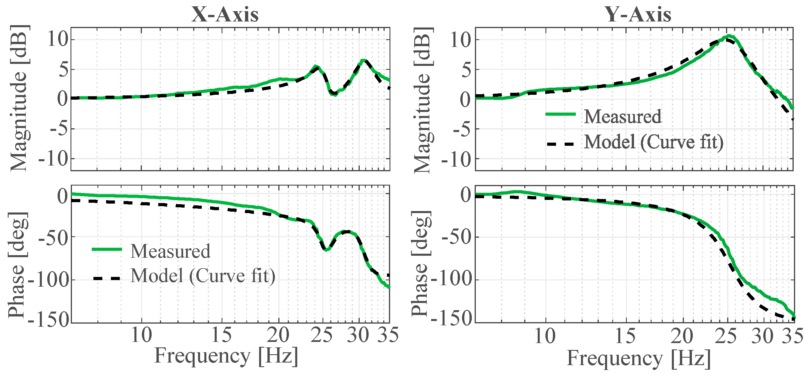
Figure 7.
Computer Assisted Design (CAD) model of Medieval Castle available at https://www.thingiverse.com/thing:884536. The full-scale height of the Castle is 457 mm. However, it is printed at 25% scale factor.
Figure 7.
Computer Assisted Design (CAD) model of Medieval Castle available at https://www.thingiverse.com/thing:884536. The full-scale height of the Castle is 457 mm. However, it is printed at 25% scale factor.

Figure 8.
Prints of Medieval Castle using: (a) local controller (Marlin); (b) cloud-based controller in South Carolina; and (c) cloud-based controller in Australia. The portions of the prints highlighted in dashed rectangles failed (broke off) during printing due to their very delicate support structures.

Figure 9.
Blobs on surface of XYZ Calibration Cube printed on a cloud-based controller with large delays primarily caused by low computational resources on a Google Compute Engine stationed in Sydney, Australia. Similar blobs can result from long transmission delays over the Internet.
Figure 9.
Blobs on surface of XYZ Calibration Cube printed on a cloud-based controller with large delays primarily caused by low computational resources on a Google Compute Engine stationed in Sydney, Australia. Similar blobs can result from long transmission delays over the Internet.
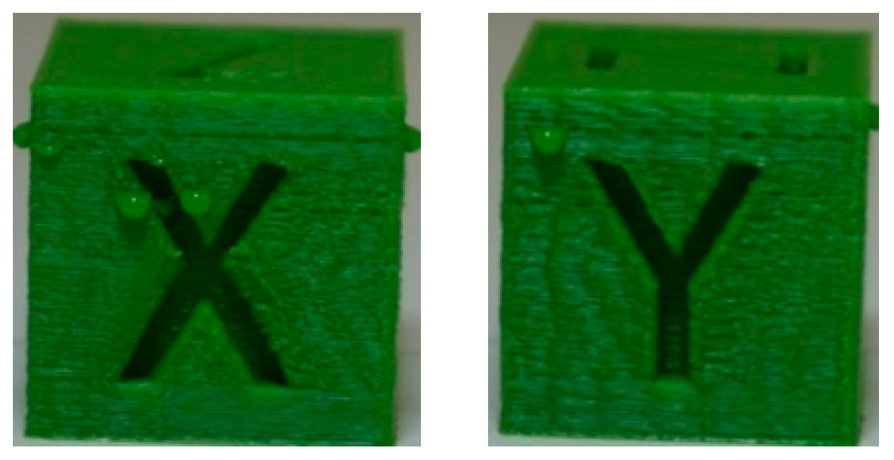
Figure 10.
Example of components of existing cloud-based 3D printing ecosystem integrated with 3DPCaaS.
Figure 10.
Example of components of existing cloud-based 3D printing ecosystem integrated with 3DPCaaS.

Table 1.
Key parameters used in Cura for slicing the Calibration Cube.
| Scale Factor | Infill Density | Layer Height | Shell Thickness | Filament | Feedrate |
|---|---|---|---|---|---|
| 100% | 20% | 0.1 mm | 1 mm | PLA | 75 mm/s |
Table 2.
Quality and printing time of X-face of Calibration Cube printed using the local controller (Marlin) as well as using a jerk-limited motion command generation (JLMCG) algorithm [30] (i.e., S-curve speed profile) and the limited-preview filtered B-spline (LPFBS) vibration compensation algorithm [31] both running on a high-end real-time control board (dSPACE DS1007). Note that the default acceleration limit and jerk speed of Taz 6 in Marlin are 0.5 m/s2 and 10 mm/s, respectively.
| Controller/Algorithm | Attribute | Acceleration Limits (m/s2) | |||
|---|---|---|---|---|---|
| 0.5 | 1 | 5 | 10 | ||
| Local controller (Marlin): Jerk Speed = 10 mm/s) | Picture | 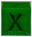 |  | 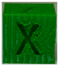 | 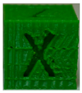 |
| Time (min) | 37:34 | 30:23 | 21:40 | 20:48 | |
| JLMCG (S-curve speed profile) running on dSPACE: Jerk Limit = 5000 m/s3 | Picture | 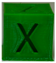 | 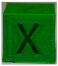 | 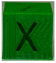 | 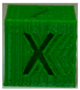 |
| Time (min) | 50:24 | 37:50 | 24:35 | 22:40 | |
| LPFBS + JLMCG running on dSPACE: Jerk Limit = 5000 m/s3 | Picture | 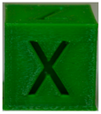 | 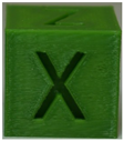 |  | 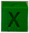 |
| Time (min) | 50:24 | 37:50 | 24:35 | 22:40 | |
Table 3.
Quality and printing time of Y-face Calibration Cube printed using the local controller (Marlin) as well as using a jerk-limited motion command generation (JLMCG) algorithm [30] (i.e., S-curve speed profile) and the limited-preview filtered B-spline (LPFBS) vibration compensation algorithm [31] both running on a high-end real-time control board (dSPACE DS1007). Note that the default acceleration limit and jerk speed of Taz 6 in Marlin are 0.5 m/s2 and 10 mm/s, respectively.
| Controller/Algorithm | Attribute | Acceleration Limits (m/s2) | |||
|---|---|---|---|---|---|
| 0.5 | 1 | 5 | 10 | ||
| Local controller (Marlin): Jerk Speed = 10 mm/s) | Picture | 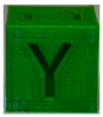 | 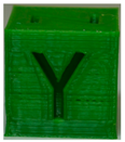 | 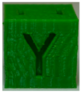 | 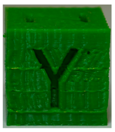 |
| Time (min) | 37:34 | 30:23 | 21:40 | 20:48 | |
| JLMCG (S-curve speed profile) running on dSPACE: Jerk Limit = 5000 m/s3 | Picture | 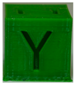 | 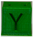 | 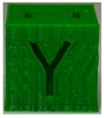 | 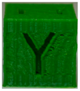 |
| Time (min) | 50:24 | 37:50 | 24:35 | 22:40 | |
| LPFBS + JLMCG running on dSPACE: Jerk Limit = 5000 m/s3 | Picture | 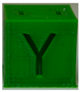 | 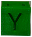 | 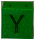 |  |
| Time (min) | 50:24 | 37:50 | 24:35 | 22:40 | |
Table 4.
Key parameters used for implementing LPFBS algorithm. Please see Reference [31] for detailed explanation and definition of symbols.
Table 4.
Key parameters used for implementing LPFBS algorithm. Please see Reference [31] for detailed explanation and definition of symbols.
| nup | nC | LC | LH | m | L |
|---|---|---|---|---|---|
| 7 | 14 | 350 | 158 | 5 | 25 |
Table 5.
Specifications of Google Compute Engine’s Virtual Machines (VMs) used for Experiments.
| Location | Region/Zone | Machine Type | CPU Platform | Operating System |
|---|---|---|---|---|
| Moncks Corner, South Carolina | US-East1-b | n1-standard-1 (1 vCPU, 3.75 GB memory) | Intel Haswell | Linux |
| Sydney, Australia | Australia-Southeast1-b | n1-standard-1 (1 vCPU, 3.75 GB memory) | Intel Broadwell | Linux |
Table 6.
Attributes of the Calibration Cube printed using a cloud-based controller stationed in Moncks Corner, South Carolina.
Table 6.
Attributes of the Calibration Cube printed using a cloud-based controller stationed in Moncks Corner, South Carolina.
| Attribute | Trial | |||
|---|---|---|---|---|
| 1 | 2 | 3 | 4 | |
| Picture of X-Face | 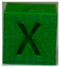 | 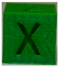 | 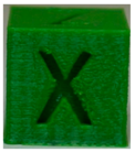 | 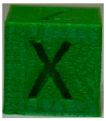 |
| Picture of Y-Face | 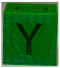 | 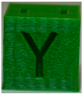 | 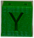 | 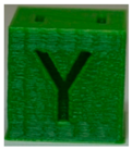 |
| Printing time (min) | 21:42 | 21:42 | 21:42 | 21:42 |
| Avg. RTT (ms) | 137 | 133 | 140 | 132 |
| Max. RTT (ms) | 216 | 237 | 724 | 221 |
| No. of Pauses | 0 | 0 | 0 | 0 |
Table 7.
Attributes of the Calibration Cube printed using a cloud-based controller stationed in Sydney, Australia.
Table 7.
Attributes of the Calibration Cube printed using a cloud-based controller stationed in Sydney, Australia.
| Attribute | Trial | |||
|---|---|---|---|---|
| 1 | 2 | 3 | 4 | |
| Picture of X-Face | 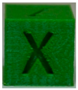 | 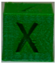 | 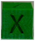 | 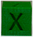 |
| Picture of Y-Face | 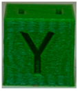 | 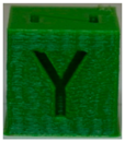 | 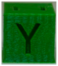 | 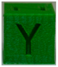 |
| Printing time (min) | 22:01 | 21:42 | 21:42 | 21:42 |
| Avg. RTT (ms) | 251 | 248 | 250 | 245 |
| Max. RTT (ms) | 469 | 403 | 586 | 252 |
| No. of Pauses | 2 | 0 | 0 | 0 |
Table 8.
Key parameters used in Cura for slicing the Medieval Castle.
| Scale Factor | Infill Density | Layer Height | Shell Thickness | Filament | Feedrate |
|---|---|---|---|---|---|
| 25% | 20% | 0.15 mm | 1 mm | PLA | 75 mm/s |
© 2018 by the authors. Licensee MDPI, Basel, Switzerland. This article is an open access article distributed under the terms and conditions of the Creative Commons Attribution (CC BY) license (http://creativecommons.org/licenses/by/4.0/).
Share and Cite
MDPI and ACS Style
Okwudire, C.E.; Huggi, S.; Supe, S.; Huang, C.; Zeng, B. Low-Level Control of 3D Printers from the Cloud: A Step toward 3D Printer Control as a Service. Inventions 2018, 3, 56. https://doi.org/10.3390/inventions3030056
AMA Style
Okwudire CE, Huggi S, Supe S, Huang C, Zeng B. Low-Level Control of 3D Printers from the Cloud: A Step toward 3D Printer Control as a Service. Inventions. 2018; 3(3):56. https://doi.org/10.3390/inventions3030056
Chicago/Turabian StyleOkwudire, Chinedum E., Sharankumar Huggi, Sagar Supe, Chengyang Huang, and Bowen Zeng. 2018. "Low-Level Control of 3D Printers from the Cloud: A Step toward 3D Printer Control as a Service" Inventions 3, no. 3: 56. https://doi.org/10.3390/inventions3030056