Cyclic Block Copolymer Microchannel Fabrication and Sealing for Microfluidics Applications


1
Department of Mechanical Engineering, National Central University, Taoyuan City 32001, Taiwan
2
R&D Division, USI Corporation, New Taipei City 224, Taiwan
3
Advanced Materials Business Unit, USI Corporation, Taipei 11492, Taiwan
*
Author to whom correspondence should be addressed.
Inventions 2018, 3(3), 49; https://doi.org/10.3390/inventions3030049
Submission received: 16 May 2018
/
Revised: 3 July 2018
/
Accepted: 13 July 2018
/
Published: 16 July 2018
(This article belongs to the Special Issue Microfluidics and Nanofluidics)
Abstract
:High mechanical rigidity, chemical resistance, and ultraviolet-visible light transmissivity of thermoplastics are attractive characteristics in microfluidics because various biomedical microfluidic devices require solvent, acid, or base manipulation, and optical observation or detection. The cyclic block copolymer (CBC) is a new class of thermoplastics with excellent optical properties, low water absorption, favorable chemical resistance, and low density, which make it ideal for use in polymer microfluidic applications. In the polymer microfabrication process, front-end microchannel fabrication and post-end bonding are critical steps that determine the success of polymer microfluidic devices. In this study, for the first time, we verified the performance of CBC created through front-end microchannel fabrication by applying hot embossing and post-end sealing and bonding, and using thermal fusion and ultraviolet (UV)/ozone surface-assist bonding methods. Two grades of CBC were evaluated and compared with two commonly used cyclic olefin polymers, cyclic olefin copolymers (COC), and cyclic olefin polymers (COP). The results indicated that CBCs provided favorable pattern transfer (>99%) efficiency and high bonding strength in microchannel fabrication and bonding procedures, which is ideal for use in microfluidics.
1. Introduction
With the development of microfluidics and lab-on-a-chip (LOC) techniques, chemical and biological analyses can be performed using a microscale channel instead of conventional glass beakers or dishes. Because of system miniaturization, the amount of a sample or reagent consumed on a microfluidic platform can be substantially reduced. Rapid sample analysis, device portability, and high system integration capability also render microfluidic platforms ideal for use in remote diagnostics or point-of-care testing applications [1,2]. In contrast to the microelectromechanical system (MEMS), which require silicon microfabrication procedures (e.g., photolithography, dry or wet etching, or deposition) to fabricate silicon-based microdevices, microfluidic devices can be fabricated using polymers. In contrast to silicon micromachining, polymer-based microfabrication techniques require cheap raw polymer materials and feasible fabrication facility requirements. These advantages make polymer-based microfluidic devices inexpensive for disposable LOC purposes [3,4,5].
The use of a polymer as a substrate material in microfluidics was proposed in the late 1990s. Following over 20 years of development, a polymer has become a major material used in microfluidics. Currently, polydimethylsiloxane (PDMS) and thermoplastics are the two most widely used polymers in microfluidics [6,7]. PDMS is a soft elastomer material, and soft lithography [8,9] is typically used to create PDMS microfluidic devices. The typical PDMS soft lithography process starts with micromold fabrication; subsequently, a PDMS mixture is poured into a micromold. After thermal curing, the PDMS replicas are removed from the micromold and bonded with another glass or a PDMS cover substrate through oxygen plasma treatment [10]. Because PDMS microfluidic devices are easy to fabricate without the need for high-end facilities or gas permeability, PDMS is a widely employed material in microfluidics, especially in cell applications [11,12]. In addition, PDMS is easily fabricated with no requirement for high-end facilities. PDMS is widely employed in polymer microfluidic chips, especially in research labs. However, PDMS devices have several drawbacks, including unsatisfactory acid and base resistance, solvent swelling, surface absorption, and lack of rigidity [13]. The PDMS casting procedure is time consuming, normally taking 1–2 h for the curing process. This fundamentally limits the fabrication throughput, which can be a potential fabrication bottleneck when considering commercialization of microfluidic devices. Compared with PDMS, thermoplastic is a rigid polymer material that can be shaped or reshaped upon heating above the glass transition temperature (Tg). Myriad thermoplastic materials, such as polycarbonate (PC) [14,15,16], polymethyl methacrylate (PMMA) [17,18,19], cyclic olefin polymers (COPs) [20,21,22,23], polystyrene (PS) [24,25,26], and polyethylene terephthalate (PET) [27,28] have been employed in microfluidics. Among them, COPs have high optical transmissivity, satisfactory solvent and acid and base resistivity, and glass-like properties. Although thermoplastics have favorable mechanical rigidity, they are not as fragile as glass, preventing accidental breakage and loss of precious samples during handling or operation procedures. In additionally, a thermoplastic material can be fabricated using replication methods, such as injection molding or roller imprinting, to mass produce polymer replicas at a low unit cost [29]. Because of these advantages, COPs are treated as emerging materials for microfluidics or LOC applications [30].
Thermoplastic microchannel fabrication techniques have been intensively developed. Becker et al. first summarized techniques for fabricating thermoplastic microfluidic chips [6,7,31]. Thereafter, the thermoplastic bonding process was reviewed by Tsao et al. [32]. In 2015, Temiz et al. summarized the thermoplastic sealing and chip-to-world fluidic, electrical, and analytical interfacing techniques [33]. These review articles have detailed the thermoplastic microfabrication process in microfluidics. Generally, thermoplastic microchannels are first created, either through replication or rapid prototyping. In replication, the microchannel in the thermoplastic substrate is inversely replicated from the master micromold. In rapid prototyping, computer numerical control (CNC) milling or laser ablation is employed to carve microfluidic channels. After microchannel fabrication, bonding is performed to create enclosed microchannels. In thermoplastic microfluidic fabrication, post-end sealing is a critical step and can be categorized as indirect or direct [32]. Indirect bonding is defined as bonding in which an additional material or a chemical reagent is used during the bonding process. Adhesive bonding is an example of an indirect bonding method. By contrast, in direct bonding, the thermoplastic pair is “directly” bonded without adding an additional material or a reagent to interface layers. Thermal fusion bonding and surface modification bonding are examples of direct bonding methods.
The cyclic block copolymer (ViviOnTM CBC) is a new class of thermoplastics with excellent optical properties, low water absorption, favorable chemical resistance, and high purity. It is suitable for high-throughput injection molding, injection blow molding, and embossing fabrication. For the first time, we verified the favorable fabrication capability and performance of CBC in microchannel fabrication, including front-end microchannel fabrication that uses the hot embossing process, and back-end microchip sealing that uses thermal fusion bonding and ultraviolet (UV)/ozone surface bonding. Two grades of cyclic block copolymers, CBC-1 and CBC-2, were evaluated. Two commonly used COPs, cyclic olefin copolymers (COC, Topas) and cyclic olefin polymers (COP, Zenon), were selected as control and comparison groups, respectively, because they have been widely used as high-performance thermoplastics in polymer microfluidics.
2. Materials and Methods
2.1. Thermoplastic Substrates
Four types of thermoplastic substrates were used, namely COC (Topas 8007; Polyplastics Co., Shizuoka, Japan), COP (Zeonor 1060R, Zeon Corp., Tokyo, Japan), and two grades of CBC (CBC-1 and CBC-2, USI Corp., Kaohsiung, Taiwan). All thermoplastic materials were obtained in the granular form and were injected into custom-made stainless steel molds to fabricate 7-cm-diameter, 2-mm-thick thermoplastic substrates for microchannel fabrication. The Tg of COC, COP, CBC-1, and CBC-2 was 78, 100, 117, and 115 °C, respectively.
2.2. Microchannel Fabrication
The microchannel was fabricated using the hot embossing process; the metal (brass) micromold was made by a CNC miller. The microchannel width and height were 200 and 50 µm, respectively. The microchannel pattern was transferred from the micromold to the thermoplastic substrate by using a hot embosser (H7-1, Raychen, Taoyuan, Taiwan). Thermoplastic substrates were cut into 50 × 50 × 2-mm substrates for microchannel fabrication. The serpentine microchannel consists of basic microchannel patterns including straight lines, angled turns, and U-turns, which meet the requirements of various microfluidic applications. Therefore, this design was used to evaluate microchannel fabrication in this study.
2.3. Water Contact Angle, and UV-VIS Transmissivity Measurements
Surface contact angles were measured using a contact angle measurement system (OCA 15EC, DataPhysics Instruments GmbH, Filderstadt, Germany). A 3-µL droplet was autopipetted onto the thermoplastic substrate to obtain contact angle data. The ultraviolet-visible light (UV-VIS) spectrum was measured through UV-VIS spectroscopy (LAMBDA 750, PerkinElmer, Waltham, MA, USA). Two-millimeter-thick thermoplastic substrates were loaded onto the UV-VIS spectroscope to obtain UV-VIS transmission data.
3. Results and Discussion
3.1. Cyclic Block Copolymer
A novel thermoplastic material, ViviOnTM CBC, was developed for biomedical and microfluidic applications. As shown in Figure 1a, CBC was a fully hydrogenated product, with a hydrogenation level of >99.5%, consisting of a styrenic block copolymer such as styrene-b-butadiene-b-styrene (SBS) and styrene-b-isoprene-b-styrene (SIS). The results of Fourier transform infrared spectroscopy analysis are presented in Figure S1. Because the CBC precursor was fabricated through anionic polymerization, the living polymerization led to high purity with low residuals. Our study results showed that this novel material had superior optical properties with light transmissivity of 92%, excellent deep UV transmission down to 210 nm, and low autofluorescence (Figure S2). High-purity CBC exhibited low leachables/extractables. The material, which was inherently non-polar, possessed superior chemical resistance to high polar solvents such as alcohol and dimethyl sulfoxide (DMSO), etc. CBC comprised only two components, carbon and hydrogen, which makes it chemically inert toward biomolecules. The thermal, mechanical, and chemical properties of CBC are presented in Tables S1 and S2. Compared with COC and COP, CBC exhibited comparable high optical, solvent, and acid and base resistance, and mechanical rigidity properties for microfluidic applications. CBC-1 and CBC-2 were polymerized using the same monomer and precursor, but different composition ratios to engender different properties (i.e., CBC-1: melt volume rate, 130 cm3/10 min at 260 °C/2.16 kg, Tg: 117 °C; CBC-2: melt volume rate, 4.5 cm3/10 min, 260 °C/2.16 kg, Tg: 115 °C).
3.2. CBC Microchannel Fabrication Using the Hot Embossing Process
The hot embossing process was chosen to fabricate the microchannel because of its simplicity and wider facility accessibility compared with injection modeling or other thermoplastic microchannel fabrication methods. Hot embossing involves four major stages (Figure 2a). First, the thermoplastic substrate is placed between the glass and brass micromold and loaded into the hot embosser; then, the temperature is increased to 20 °C above the thermoplastic’s Tg (Stage A). Subsequently, 1.96 MPa (20 kg/cm2) of pressure is applied and maintained for 5 min to allow complete pattern transfer from the micromold to the thermoplastic substrate (Stage B). Afterward, the temperature is reduced to approximately 20 °C below the material’s Tg while 1.96 MPa (Stage C) of pressure is maintained. The constant pressure in stage C ensured adequate microchannel dimension integrity that prevented microchannel shrinkage and deformation during the cooling process. Finally, the pressure is reduced, and cooling to initial room temperature was permitted. The thermoplastic replica was removed from the micromold to complete microchannel fabrication (Stage D). As shown in Figure 2b, favorable thermoplastic pattern transfer efficiency (>99%) with approximately 200 (width) × 50 μm (height) was achieved through hot embossing.
3.3. Bonding of the CBC Thermoplastic Microchannel
Bonding is a critical step in the success of thermoplastic microfluidic devices. Several factors must be considered when deciding on the thermoplastic bonding process. Bonding strength is the most critical and must be prioritized when evaluating bonding performance. Bonding must be sufficiently strong to hold the thermoplastic chip without leakage during microfluidic chip flow injection as well as during operation. For standard microfluidic handling and transportation conditions, low-medium bonding strength is sufficient to hold the chip. When operating at high flow rates or in high-hydraulic resistance microchannels (e.g., porous monoliths and bead-packed microchannels), the high bond strength bonding method should be considered. To measure bonding strength, the crack opening method was used [20]. In this experiment, a 0.25-mm-thick razor blade was inserted into the bonding interface, causing delamination. By measuring delamination length, bonding strength can be calculated using Equation (1) [34]. In this experiment, a 0.25 mm thick razor blade is inserted at the bonding interface to cause the delamination. By measuring the delamination length, bonding strength could be calculated by Equation (1).
where E is the elastic modulus of the thermoplastic substrate. In this study, the elastic moduli of COC, COP, CBC-1, and CBC-2 were 2.1, 2.1, 2.5, and 1.7 GPa, respectively. t is the thickness of the substrates, which is at least 2 mm; y is half of the blade thickness, which is 125 μm, and L is delamination length. For thermal fusion bonding and the UV/ozone bonding process discussed in the following sections, the thermoplastic substrates were placed in the hot embosser and sandwiched between two glass plates to ensure an optical smooth surface after bonding. The bonding experiment setup is shown in Figure S3.
3.3.1. Thermal Fusion Bonding of the CBC Microchannel
Thermal fusion bonding, also called thermal bonding, is among the commonest methods for sealing thermoplastic microfluidic chips because of its simplicity. Thermal fusion bonding is achieved by heating thermoplastic pairs above Tg where the thermoplastic becomes rubbery and can be deformed upon application of pressure. At the bonding interface, polymer chains fuse together through interdiffusion. This simple thermal pressure bonding mechanism is straightforward without any further modification; furthermore, it retains the homogenous microchannel surface properties following the bonding process. Microchannel clogging and deformation are concerns in thermal fusion bonding. To ensure a higher bonding strength, a higher bonding temperature can be used in the thermal fusion bonding process. However, this may cause microchannel deformation or even microchannel clogging or collapse. The main bonding parameters of thermal fusion bonding are temperature, time, and pressure. During the bonding process, the temperature rises close to Tg for polymer chain interfusion at the bonding interface; the pressure enhances surface contact at the bonding interface to overcome surface roughness. Adequate bonding time ensures sufficient bond generation on the bonding interface. In our preliminary investigation, we determined that bonding temperature plays a key role in microchannel clogging or collapse. To determine the optimal thermal fusion bonding condition to prevent microchannel collapsing, as shown in Table 1, various thermal fusion bonding parameters were examined in this investigation.
Figure 3 presents the thermal bonding strength (blue line) and substrate thickness (red line) for various temperatures. No thermal fusion bonds were observed for COC (Figure 3c) and COP (Figure 3d) when bonding temperatures were set 20 °C below their respective Tg (58 °C for COC and 80 °C for COP). CBC substrates can generate bonding at 20 °C below Tg. A bond force of approximately 0.59 mJ/cm2 was achieved when the CBC bonding pair was bonded at 40 °C below CBC-1′s Tg, and the highest bonding strength (6.1 mJ/cm2) was observed at a bonding temperature of 107 °C for CBC-1 (Figure 3a). Similar to CBC-1, 0.13 mJ/cm2 bonds can be generated at 40 °C below CBC-2’s Tg, and the highest bonding strength (1.2 mJ/cm2) was achieved at a bonding temperature of 115 °C (Figure 3b). The thermal plastic materials of CBC exhibited higher bond strength than did those of COC and COP. The highest bonding strength of CBC-1 (6.1 mJ/cm2) was 15 and 5.5 times higher than that of COC (0.4 mJ/cm2) and COP (1.1 mJ/cm2), respectively. This is presumably because CBCs exhibit a higher polymer reflow capability than do COC and COP. A rheometer (Discovery Hybrid Rheometer, model HR-1, TA Instruments, Eden Prairie, MN, USA) was employed (Figure 3e), and it revealed that CBC-1 had the lowest complex viscosity, which promoted polymer chain interdiffusion and exchange at the bonding interface, resulting in greater bonding strength. In our microchannel fabrication attempt, in addition to preventing microchannel collapse, we also sought substrate deformation of <10%. Therefore, we selected the optimal thermal fusion bonding temperatures of 97, 85, 68, and 90 °C for CBC-1, CBC-2, COC, and COP, respectively. As shown in Figure 3f, no microchannel collapse was observed at these optimal bonding temperatures.
3.3.2. Surface Treatment Bonding of CBC Microchannels through UV/ozone Modification
Pressure and heat application during thermal fusion bonding are likely to cause microchannel deformation. Low-temperature bonding is a superior method for sealing microchannels. Surface modification methods are also commonly applied to thermoplastic surfaces to promote bonding performance. The surface treatment bonding method renders thermoplastic surfaces hydrophilic, which promotes surface wettability and surface energy; high surface energy generates strong bonds at the interface at low temperatures. In this study, we selected the UV/ozone bonding method to evaluate CBC surface treatment bonding because a UV/ozone cleaner is affordable [35]. UV/ozone treatment modifies thermoplastic substrates by exposing them to UV light in an air-filled chamber. UV light has wavelengths of 184.9 nm and 253.7 nm under atmospheric pressure conditions. The UV light at 184.9 nm decomposes oxygen molecules and synthesizes ozone. Simultaneously, the UV light at 253.7 nm decomposes ozone molecules, rapidly oxidizing hydrocarbons and producing high-energy oxygen radicals on the thermoplastic surface [35,36].
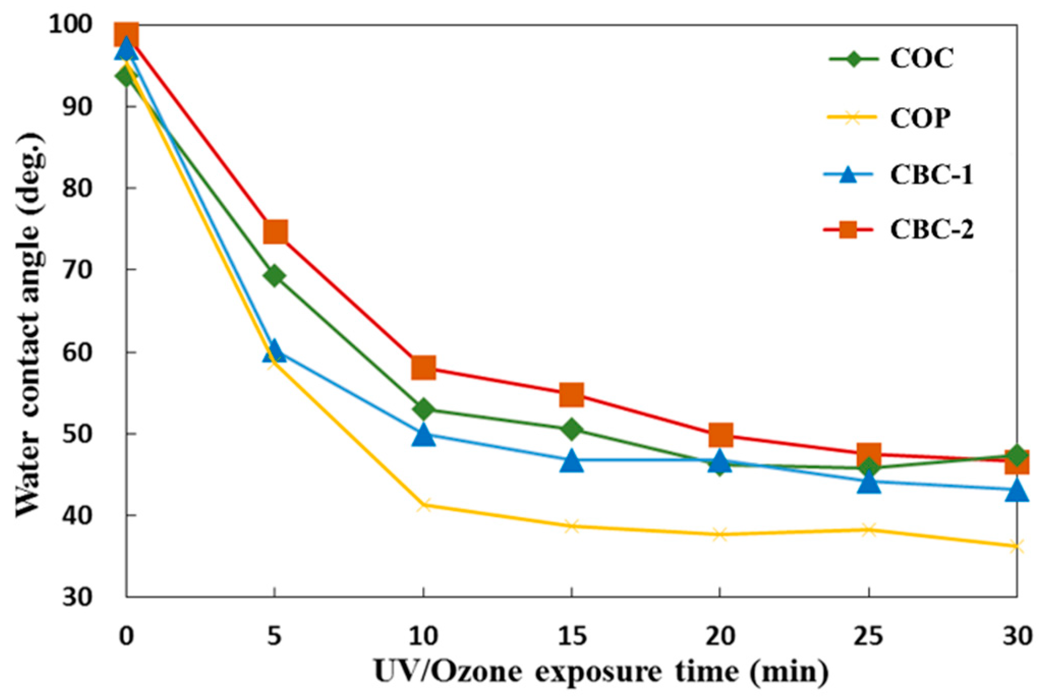
The UV/ozone treatment modifies the thermoplastic surface by altering the surface wettability of the microchannel, which is a key consideration for microfluidic applications. After UV/ozone surface treatment, surface hydrophobicity variations were evaluated. Figure 4 presents water contact angles and UV/ozone surface treatment time. CBCs exhibited weak hydrophobicity of 97.20° (CBC-1, blue line in Figure 4) and 98.81° (CBC-2, orange line in Figure 4) in native stages. Under the UV/ozone surface treatment, the water contact angle on CBC surfaces decreased to 49.97° (CBC-1) and 58.14° (CBC-2) within 10 min. After 10 min, it plateaued and gradually reduced the water contact angle as surface treatment increased. The water contact angle decreased to 43.25° (CBC-1) and 46.61° (CBC-2) after 30-min UV/ozone treatment. These trends were similar to those for COC (Figure 4, green line) and COP (yellow line) surfaces under UV/ozone treatment.
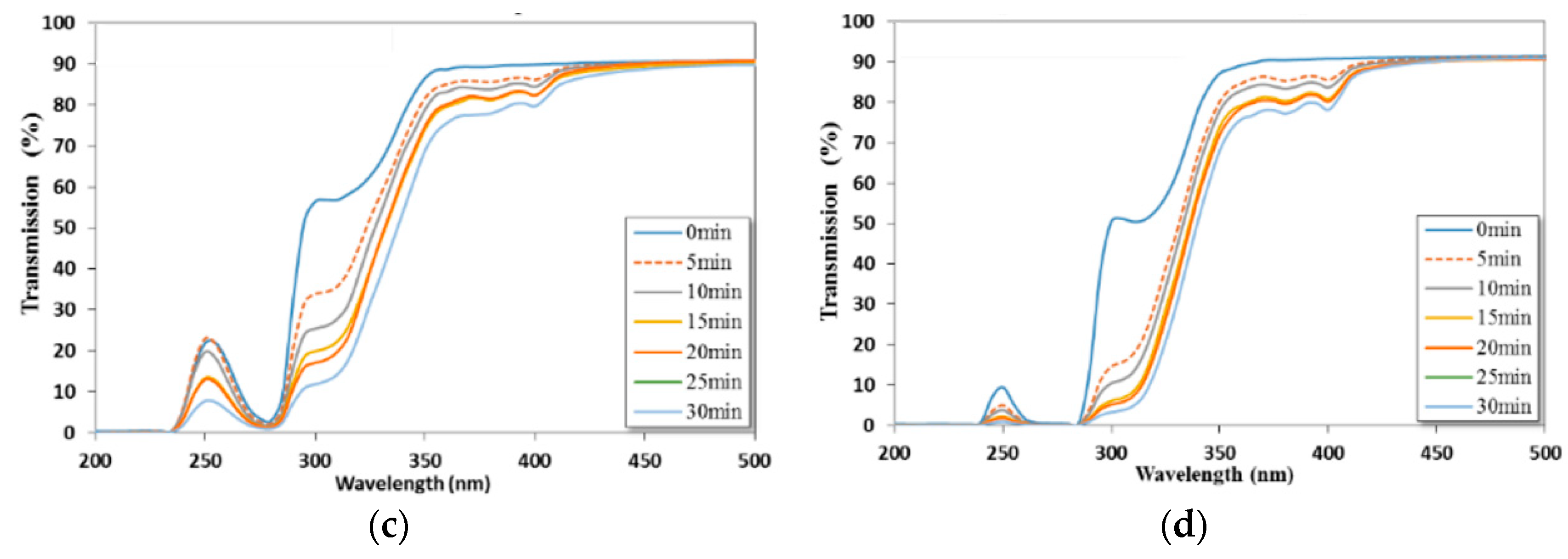
In addition to surface hydrophobicity reduction, the surface optical transmissivity of COC and COP substrates decreased, which may potentially affect the performance of optical microfluidic applications. Figure 5a,b shows the optical transmissivity of CBC thermoplastic substrates after surface modification and compares them with that of COC and COP substrates (Figure 5c,d). The COC, COP, and CBCs not only showed favorable optical transmissivity in the visible range of >90%, but they also have more favorable optical transmissivity in the mid- and near-UV ranges compared with other thermoplastic substrates. CBC-1 had the highest UV range transmissivity (~51% in the 250-nm range and ~64% in the 300-nm range) compared with COC (~23% in the 250-nm range and ~57% in the 300-nm range), COP (~10% in the 250-nm range and ~52% in the 300-nm range), and CBC-2 (~19% in the 250-nm range and ~29% in the 300-nm range) in the native stage (0 min). Under UV/ozone surface treatment, the optical transmissivity decreased with UV/ozone treatment time. After 30-min UV/ozone treatment, the optical transmissivity of CBC-1 degraded to approximately 22% in the 250-nm range and to ~15% in the 300-nm range. Similar phenomena were observed for COC, COP, and CBC-2 (Figure 5).
After hydrophobicity and optical transmissivity effects were evaluated, bonding strength experiments with various UV/ozone exposure times were performed. We sought the shortest UV/ozone time for optimum bonding strength to minimize optical degradation and reduce the processing time during the UV/ozone bonding process. The bonding pressure and time were fixed at 30 kg/cm2 and 20 min, respectively. The bonding temperature was set 40 °C below Tg to minimize the temperature effects, except for that of COC, which was set 20 °C below Tg because the Tg of COC is low (78 °C).
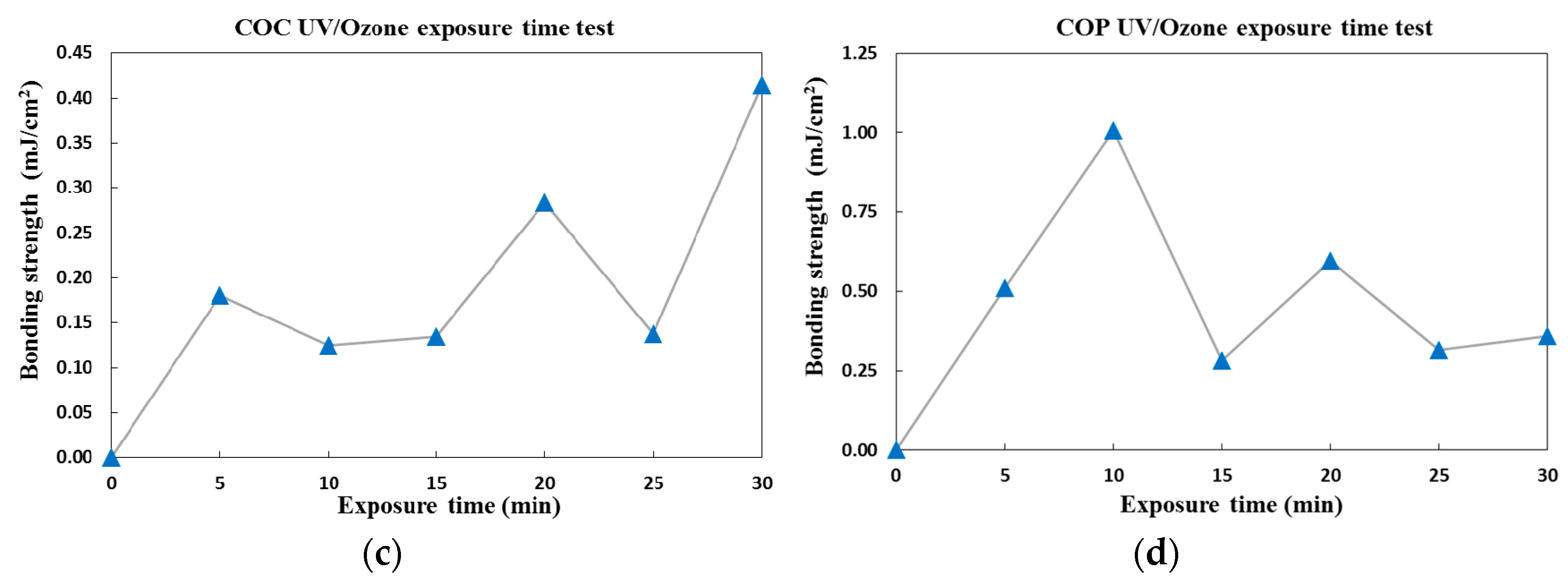
Figure 6 shows the bonding strength of substrates for UV/ozone exposure times from 0 to 30 min. The results indicated that longer UV/ozone exposure times did not yield greater bonding strength, and the optimal exposure time was determined for each thermoplastic. In our previous surface hydrophobicity experiments (Figure 4), longer UV/ozone exposure times resulted in superior surface wettability with a higher surface energy because of the surface oxidation mechanism. However, during the UV/ozone bonding process, oxygen molecules that bombard the thermoplastic surface generate rough surfaces. These rough surfaces create obstacles for generating intimate surface contact, resulting in weaker bonds at the bond interface. Because of the effects of surface wettability and surface flatness, UV/ozone exposure time was optimized. The optimized UV/ozone surface exposure time for CBC-1 and CBC-2 was 5 min with approximately 1.1 and 3.7 mJ/cm2 of bonding strength, respectively (Figure 6a,b, respectively). This represents greater bonding strength with a shorter UV/ozone surface treatment time compared with COC (30 min, ~0.4 mJ/cm2, Figure 6c) and COP (10 min, ~0.1 mJ/cm2, Figure 6d).
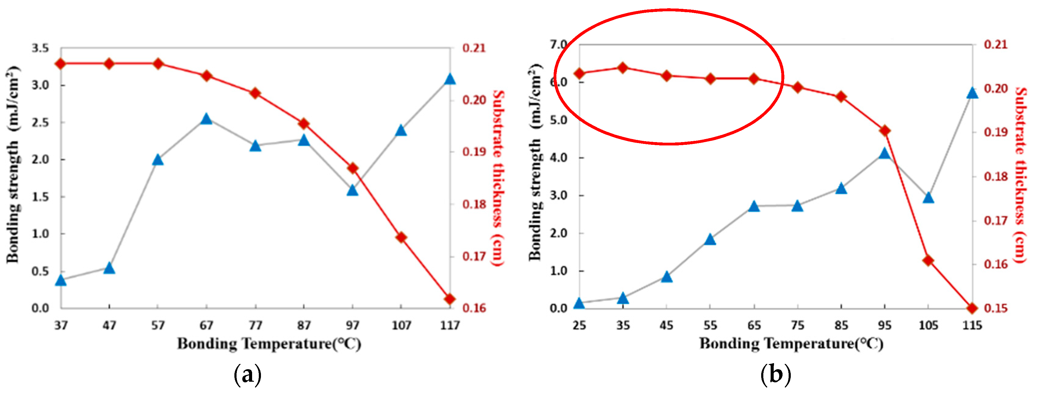
After we obtained the optimal UV/ozone exposure time of each material, the bonding strength of each material following UV/ozone surface modification was evaluated. The bonding strength of CBC-1 was approximately 2.0 mJ/cm2 at a low temperature of 57 °C (Figure 7a). Because the bonding temperature was 60 °C below Tg, minimal substrate deformation was observed at that temperature (Figure 7b). Similarly, for CBC-2, the bonding strength was approximately 3.0 mJ/cm2 at 65 °C with little variation in substrate thickness. Similarly, low bonding temperatures were achieved for COC and COP substrates with strong bonds and minimal substrate deformation. The bonding strength was approximately 0.8 mJ/cm2 at 58 °C and 1.2 mJ/cm2 at 80 °C for COC and COP as shown in Figure 7c,d, respectively. Because the UV/ozone treatment can effectively reduce the bonding temperature and enhance bonding strength, optimal bonding temperatures of 67, 75, 68, and 80 °C are recommended for CBC-1, CBC-2, COC and COP, respectively to obtain high-strength bonds and few microchannel deformations.
CBC microchannel performance was evaluated and compared. Figure 8 shows the optimized UV/ozone bonding strength and CBC’s UV-VIS transmissivity after UV/ozone treatment. Among the thermoplastic materials we investigated in this study, both CBC-1 and CBC-2 exhibited high bonding strength at low bonding temperatures of 67 and 75 °C, respectively, within 5 min of UV/ozone treatment time. Because the UV/ozone treatment exposure time was decreased, the side effects of UV-VIS degradation maintains high transmissivity values for CBC-1 and CBC-2 compared with other thermoplastic materials that we investigated (Figure 8b).
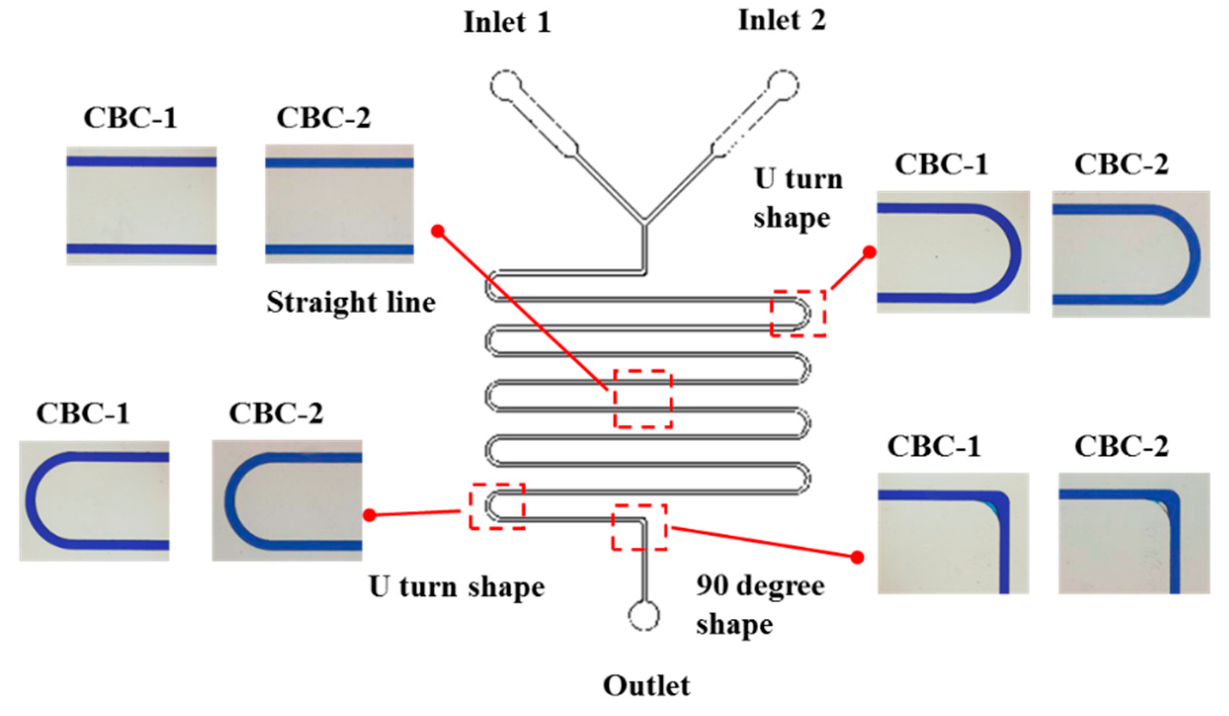
Finally, leakage tests were performed on CBC-1 and CBC-2 microchannels to ensure no leakages occurred during the microfluidic channel operation. As shown in Figure 9, no fluid leakages were observed following syringe pump fluid injection, which demonstrates successful use of CBC thermoplastics with high bond strength and high optical performance in microfluidic applications.
4. Conclusions
A high-performance CBC thermoplastic created through hydrogenation from styrene-butadiene block copolymers is reported. Our CBC exhibited high optical transmissivity and chemical and solvent resistivity, which make it ideal for use in polymer microfluidic applications. In this study, we investigated polymer microchannel fabrication procedures to evaluate the effectiveness of applying CBC to microfluidic applications. A hot embossing process was used as the front-end process to fabricate microchannels as front-end process. Thermal fusion bonding and UV/Ozone surface assisted bonding were invested employed as the back-end processes to seal the imprinted microchannel into an enclosed microfluidic network. The results indicated that for microchannel fabrication, because of favorable CBC reflow behavior during the hot embossing process, the microchannel patterns on the micromold were fully transferred onto the CBC substrate. In thermal fusion bonding, high bond strength was observed in the CBC-1 substrate, which was 15 and 5.5 times higher than that of COC and COP substrates, respectively. UV/ozone exposure effectively increased surface energy and bonding strength, and reduced the bonding temperature. An optimal UV/ozone exposure time of 5 min was ascertained for CBC substrates. This short exposure time not only reduced the bonding process time for superior fabrication throughputs, but also minimized the UV-VIS degradation effects. The results proved that CBC-1 shows best optical performance with high bond strength, and CBC-2 displays the best bond strength, but with a more degraded optical performance.
Supplementary Materials
The following are available online at https://www.mdpi.com/2411-5134/3/3/49/s1, Table S1: Comparison of general thermal and mechanical properties of COC, COP, and CBC; and Table S2: Comparison of chemical resistance properties of COC, COP, and CBC. Figure S1: The Fourier Transform Infrared Spectroscopy (FTIR) analysis of CBC. Figure S2: Auto-fluorescence measurement of CBC-1 comparing to polystyrene. Figure S3. Experiment setup for thermal fusion and UV/Ozone bonding.
Author Contributions
C.-Y.Y. contributed to the experiment operations, data collection, and analysis the data. M.-C.O.C. contributed to the experiment facility and project management. Z.-F.S. contributed to the CBC substrate prepare and property analysis. Y.-H.L. contributed to the applications for CBC microfluidic device. And C.-W.T. contributed to organizing the research plans and data analysis, writing the paper, and obtaining and managing the research grants for this research project.
Funding
This research was funded by Ministry of Science and Technology, Taiwan (MOST 106-2221-E-008-057) and technical and financial support from USI Corporation.
Conflicts of Interest
The authors declare no conflict of interest.
References
- Sackmann, E.K.; Fulton, A.L.; Beebe, D.J. The present and future role of microfluidics in biomedical research. Nature 2014, 507, 181–189. [Google Scholar] [CrossRef] [PubMed]
- Pandey, C.M.; Augustine, S.; Kumar, S.; Kumar, S.; Nara, S.; Srivastava, S.; Malhotra, B.D. Microfluidics based point-of-care diagnostics. Biotechnol. J. 2018, 13. [Google Scholar] [CrossRef] [PubMed]
- Kuo, J.S.; Chiu, D.T. Disposable microfluidic substrates: Transitioning from the research laboratory into the clinic. Lab Chip 2011, 11, 2656–2665. [Google Scholar] [CrossRef] [PubMed]
- Zhang, X.J.; Zhu, Z.X.; Ni, Z.H.; Xiang, N.; Yi, H. Inexpensive, rapid fabrication of polymer-film microfluidic autoregulatory valve for disposable microfluidics. Biomed. Microdevices 2017, 19. [Google Scholar] [CrossRef] [PubMed]
- Cho, H.; Kim, J.; Jeon, C.-W.; Han, K.-H. A disposable microfluidic device with a reusable magnetophoretic functional substrate for isolation of circulating tumor cells. Lab Chip 2017, 17, 4113–4123. [Google Scholar] [CrossRef] [PubMed]
- Becker, H.; Gartner, C. Polymer microfabrication technologies for microfluidic systems. Anal. Bioanal. Chem. 2008, 390, 89–111. [Google Scholar] [CrossRef] [PubMed]
- Becker, H.; Locascio, L.E. Polymer microfluidic devices. Talanta 2002, 56, 267–287. [Google Scholar] [CrossRef]
- Qin, D.; Xia, Y.; Whitesides, G.M. Soft lithography for micro- and nanoscale patterning. Nat. Protocols 2010, 5, 491–502. [Google Scholar] [CrossRef] [PubMed] [Green Version]
- Xia, Y.N.; Whitesides, G.M. Soft lithography. Angew. Chem. Int. Ed. 1998, 37, 550–575. [Google Scholar] [CrossRef]
- Eddings, M.A.; Johnson, M.A.; Gale, B.K. Determining the optimal pdms-pdms bonding technique for microfluidic devices. J. Micromech. Microeng. 2008, 18, 067001. [Google Scholar] [CrossRef]
- Velve-Casquillas, G.; Le Berre, M.; Piel, M.; Tran, P.T. Microfluidic tools for cell biological research. Nano Today 2010, 5, 28–47. [Google Scholar] [CrossRef] [PubMed] [Green Version]
- Halldorsson, S.; Lucumi, E.; Gomez-Sjoberg, R.; Fleming, R.M.T. Advantages and challenges of microfluidic cell culture in polydimethylsiloxane devices. Biosens. Bioelectron. 2015, 63, 218–231. [Google Scholar] [CrossRef] [PubMed]
- Mukhopadhyay, R. When pdms isn‘t the best. Anal. Chem. 2007, 79, 3248–3253. [Google Scholar] [CrossRef] [PubMed]
- Liu, Y.; Ganser, D.; Schneider, A.; Liu, R.; Grodzinski, P.; Kroutchinina, N. Microfabricated polycarbonate ce devices for DNA analysis. Anal. Chem. 2001, 73, 4196–4201. [Google Scholar] [CrossRef] [PubMed]
- Hu, Z.L.; Chen, X.; Yao, Z.; Chen, X.D.; Fu, B.D.; Zhang, L. Fabricated polycarbonate microchannel with different films using CO2 laser beam of two-pass for microfluidic chip. Microsyst. Technol. 2018, 24, 2325–2331. [Google Scholar] [CrossRef]
- Witek, M.A.; Hupert, M.L.; Park, D.S.W.; Fears, K.; Murphy, M.C.; Soper, S.A. 96-well polycarbonate-based microfluidic titer plate for high-throughput purification of DNA and rna. Anal. Chem. 2008, 80, 3483–3491. [Google Scholar] [CrossRef] [PubMed]
- Li, Y.P.; Xu, T.; Chen, X.M.; Lin, S.; Cho, M.; Sun, D.; Yang, M.S. Effects of direct current electric fields on lung cancer cell electrotaxis in a pmma-based microfluidic device. Anal. Bioanal. Chem. 2017, 409, 2163–2178. [Google Scholar] [CrossRef] [PubMed]
- Liga, A.; Morton, J.A.S.; Kersaudy-Kerhoas, M. Safe and cost-effective rapid-prototyping of multilayer pmma microfluidic devices. Microfluid. Nanofluid. 2016, 20, 164. [Google Scholar] [CrossRef]
- Tan, H.Y.; Loke, W.K.; Nguyen, N.-T. A reliable method for bonding polydimethylsiloxane (pdms) to polymethylmethacrylate (pmma) and its application in micropumps. Sens. Actuators B Chem. 2010, 151, 133–139. [Google Scholar] [CrossRef]
- Azouz, A.B.; Murphy, S.; Karazi, S.; Vázquez, M.; Brabazon, D. Fast fabrication process of microfluidic devices based on cyclic olefin copolymer. Mater. Manuf. Process. 2014, 29, 93–99. [Google Scholar] [CrossRef] [Green Version]
- Jena, R.K.; Yue, C.Y.; Lam, Y.C. Micro fabrication of cyclic olefin copolymer (COC) based microfluidic devices. Microsyst. Technol. 2011, 18, 159–166. [Google Scholar] [CrossRef]
- Zhang, J.; Das, C.; Fan, Z.H. Dynamic coating for protein separation in cyclic olefin copolymer microfluidic devices. Microfluid. Nanofluid. 2007, 5, 327–335. [Google Scholar] [CrossRef]
- Steigert, J.; Haeberle, S.; Brenner, T.; Müller, C.; Steinert, C.P.; Koltay, P.; Gottschlich, N.; Reinecke, H.; Rühe, J.; Zengerle, R.; et al. Rapid prototyping of microfluidic chips in COC. J. Micromech. Microeng. 2007, 17, 333–341. [Google Scholar] [CrossRef]
- Pentecost, A.M.; Martin, R.S. Fabrication and characterization of all-polystyrene microfluidic devices with integrated electrodes and tubing. Anal. Methods 2015, 7, 2968–2976. [Google Scholar] [CrossRef] [PubMed]
- Chan, C.Y.; Goral, V.N.; DeRosa, M.E.; Huang, T.J.; Yuen, P.K. A polystyrene-based microfluidic device with three-dimensional interconnected microporous walls for perfusion cell culture. Biomicrofluidics 2014, 8, 046505. [Google Scholar] [CrossRef] [PubMed] [Green Version]
- Johnson, A.S.; Anderson, K.B.; Halpin, S.T.; Kirkpatrick, D.C.; Spence, D.M.; Martin, R.S. Integration of multiple components in polystyrene-based microfluidic devices part I: Fabrication and characterization. Analyst 2013, 138, 129–136. [Google Scholar] [CrossRef] [PubMed]
- Li, J.M.; Liu, C.; Qiao, H.C.; Zhu, L.Y.; Chen, G.; Dai, X.D. Hot embossing/bonding of a poly(ethylene terephthalate) (PET) microfluidic chip. J. Micromech. Microeng. 2008, 18, 015008. [Google Scholar] [CrossRef]
- Hu, Z.L.; Chen, X.Y. Fabrication of polyethylene terephthalate microfluidic chip using CO2 laser system. Int. Polym. Proc. 2018, 33, 106–109. [Google Scholar] [CrossRef]
- Tsao, C.W. Polymer microfluidics: Simple, low-cost fabrication process bridging academic lab research to commercialized production. Micromachines 2016, 7, 225. [Google Scholar] [CrossRef]
- Nunes, P.S.; Ohlsson, P.D.; Ordeig, O.; Kutter, J.P. Cyclic olefin polymers: Emerging materials for lab-on-a-chip applications. Microfluid. Nanofluid. 2010, 9, 145–161. [Google Scholar] [CrossRef]
- Becker, H.; Gartner, C. Polymer microfabrication methods for microfluidic analytical applications. Electrophoresis 2000, 21, 12–26. [Google Scholar] [CrossRef]
- Tsao, C.W.; DeVoe, D.L. Bonding of thermoplastic polymer microfluidics. Microfluid. Nanofluid. 2009, 6, 1–16. [Google Scholar] [CrossRef]
- Temiz, Y.; Lovchik, R.D.; Kaigala, G.V.; Delamarche, E. Lab-on-a-chip devices: How to close and plug the lab? Microelectron. Eng. 2015, 132, 156–175. [Google Scholar] [CrossRef]
- Maszara, W.P.; Goetz, G.; Caviglia, A.; McKitterick, J.B. Bonding of silicon wafers for silicon-on-insulator. J. Appl. Phys. 1988, 64, 4943. [Google Scholar] [CrossRef]
- Tsao, C.W.; Hromada, L.; Liu, J.; Kumar, P.; DeVoe, D.L. Low temperature bonding of pmma and coc microfluidic substrates using uv/ozone surface treatment. Lab Chip 2007, 7, 499–505. [Google Scholar] [CrossRef] [PubMed]
- Shinohara, H.; Mizuno, J.; Shoji, S. Studies on low-temperature direct bonding of vuv, vuv/o3 and o2 plasma pretreated cyclo-olefin polymer. Sens. Actuators A Phys. 2011, 165, 124–131. [Google Scholar] [CrossRef]
Figure 1.
Hydrogenation process for forming a cyclic block copolymer.
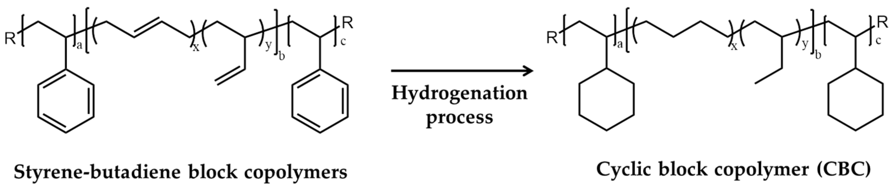
Figure 2.
(a) Thermoplastic microchannel fabrication process; (b) Cross-section of the CBC thermoplastic replica. The cross-sectional image was obtained by casting the polydimethylsiloxane (PDMS) elastomer from the CBC microchannel replica and cutting it using a razor blade. The image was taken using an inverted microscope (Nikon Eclipse Ti).
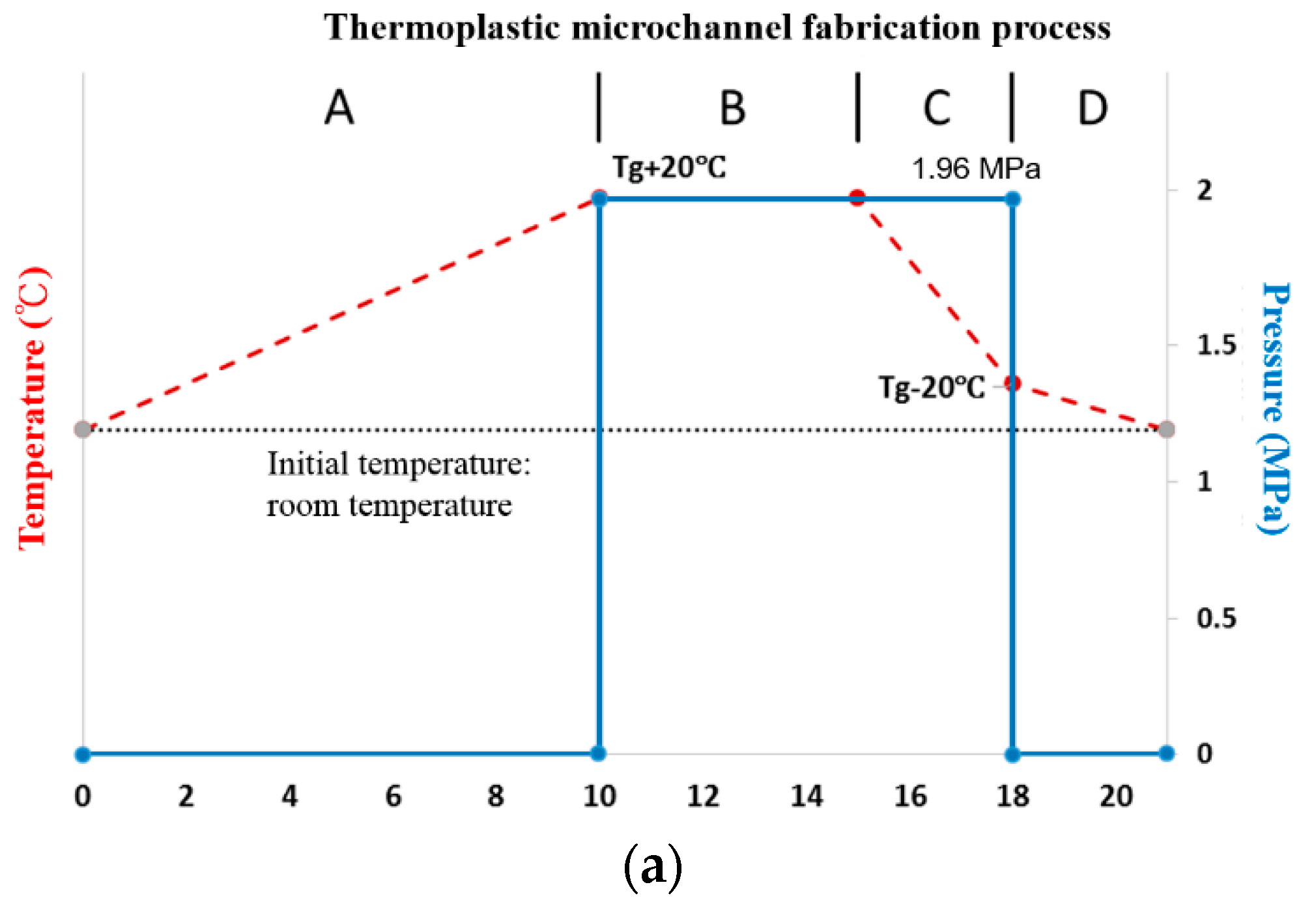
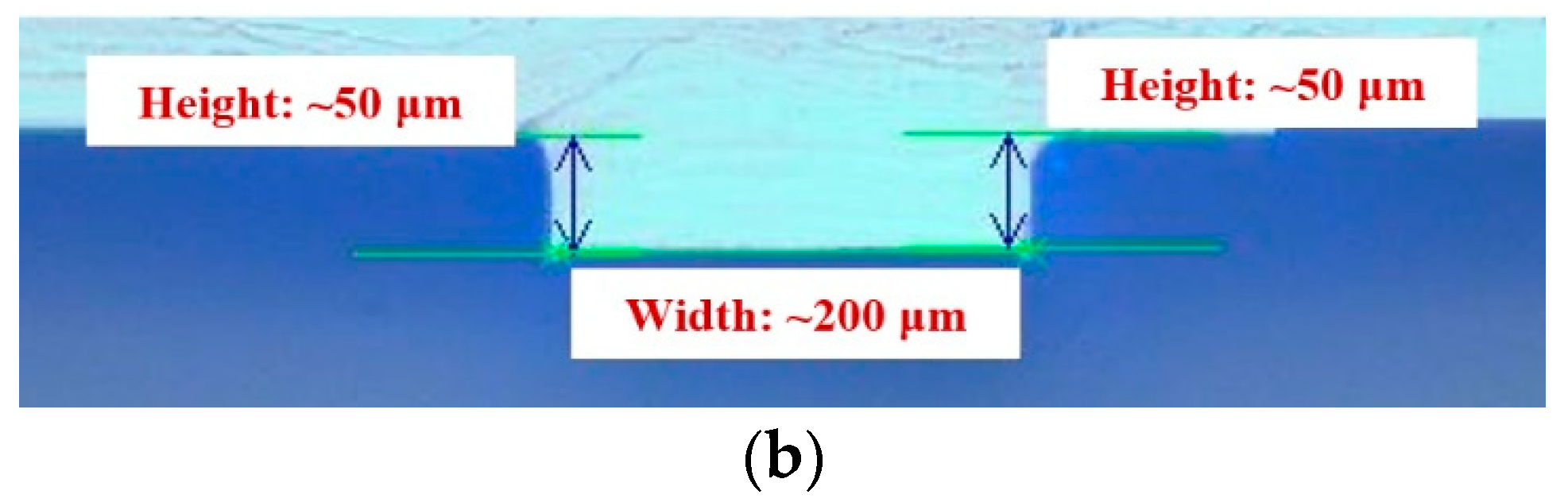
Figure 3.
Thermoplastic bonding strength (blue line) and thermoplastic substrate thickness after bonding (red line) for various bonding temperatures for (a) CBC-1, (b) CBC-2, (c) COC, and (d) COP. (e) Complex viscosity measurement for CBC-1, COC, and COP. The bonding strength and substrate thickness values are averaged on the basis of three individual measurements; (f) Microchannels injected with a blue food dye (15 μL/min). No microchannel collapse can be observed under optimal bonding conditions. The bonding strength drop at 117 °C for CBC-1 was because the polymer stuck to the glass during the release of bonded pairs. The operating conditions when the complex viscosity was measured were 250 °C, strain: 5% in N2 gas.
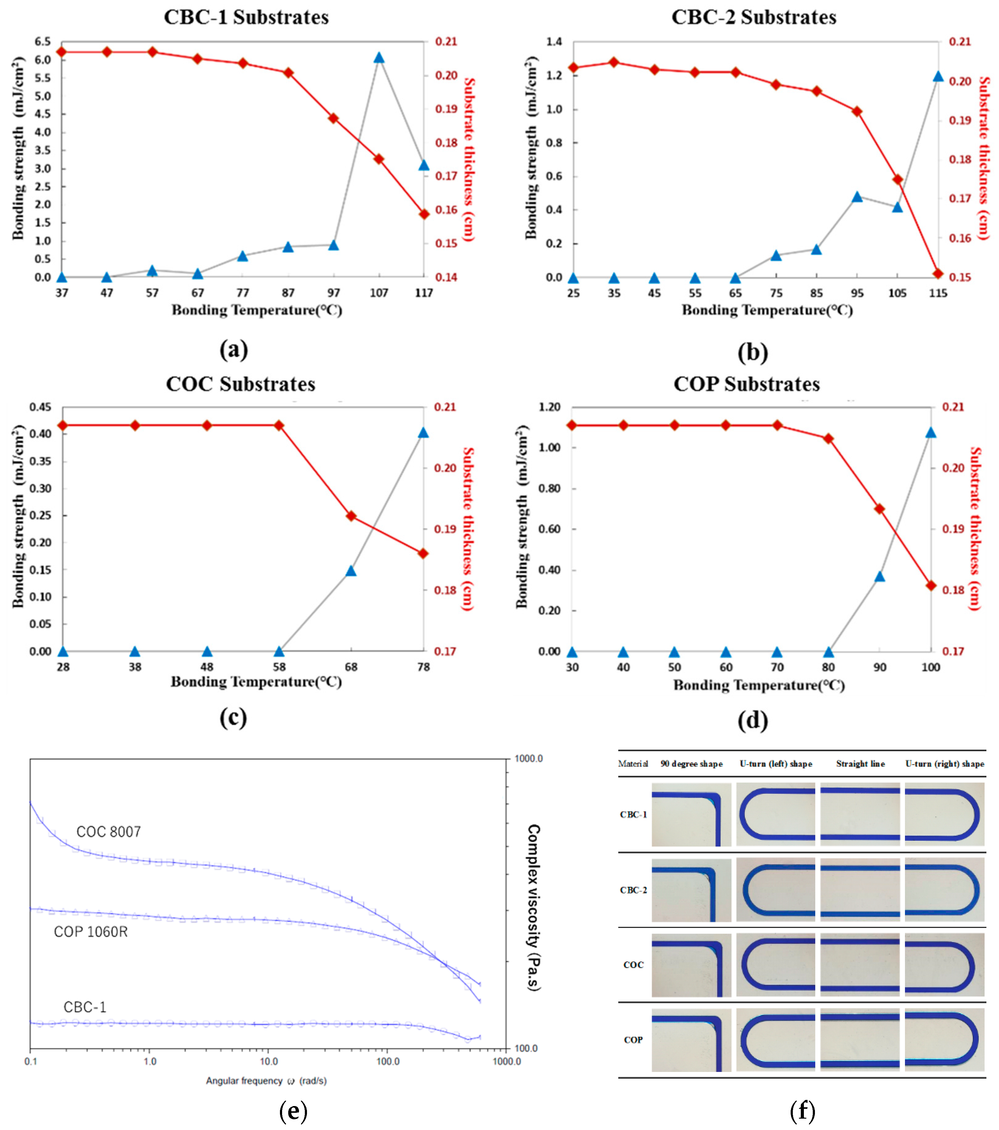
Figure 4.
Water contact angle measurements for CBC-1, CBC-2, COC, and COP surfaces by ultraviolet (UV)/ozone exposure time. The contact angles values are the average of three individual measurements.
Figure 4.
Water contact angle measurements for CBC-1, CBC-2, COC, and COP surfaces by ultraviolet (UV)/ozone exposure time. The contact angles values are the average of three individual measurements.

Figure 5.
Optical transmissivity of (a) CBC-1, (b) CBC-2, (c) COC, and (d) COP thermoplastic substrates with UV/ozone treatment times from 0 to 30 min.
Figure 5.
Optical transmissivity of (a) CBC-1, (b) CBC-2, (c) COC, and (d) COP thermoplastic substrates with UV/ozone treatment times from 0 to 30 min.


Figure 6.
UV/ozone bonding strength with exposure times from 0 to 30 min for (a) CBC-1, (b) CBC-2, (c) COC, and (d) COP thermoplastic substrates. The bonding strength values are the average of three individual measurements.
Figure 6.
UV/ozone bonding strength with exposure times from 0 to 30 min for (a) CBC-1, (b) CBC-2, (c) COC, and (d) COP thermoplastic substrates. The bonding strength values are the average of three individual measurements.
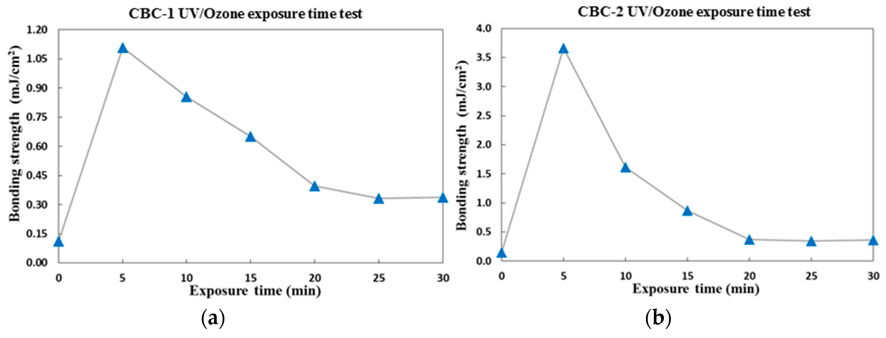

Figure 7.
UV/ozone bonding strength (blue line) and substrate thickness (red line) for (a) CBC-1, (b) CBC-2, (c) COC, and (d) COP. The bonding strength values are the average of three individual measurements.
Figure 7.
UV/ozone bonding strength (blue line) and substrate thickness (red line) for (a) CBC-1, (b) CBC-2, (c) COC, and (d) COP. The bonding strength values are the average of three individual measurements.

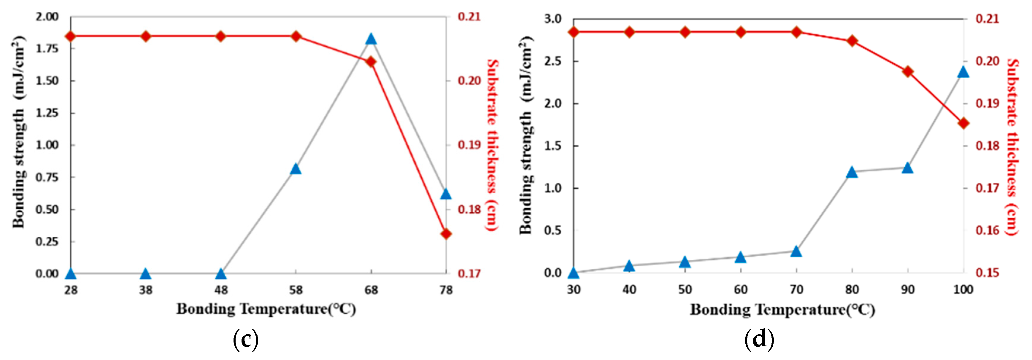
Figure 8.
(a) UV/ozone bonding strength and (b) ultraviolet-visible light (UV-VIS) transmissivity after UV/ozone treatment for CBC-1, CBC-2, COP, and COC substrates. The bonding strength values are the average of three individual measurements.
Figure 8.
(a) UV/ozone bonding strength and (b) ultraviolet-visible light (UV-VIS) transmissivity after UV/ozone treatment for CBC-1, CBC-2, COP, and COC substrates. The bonding strength values are the average of three individual measurements.
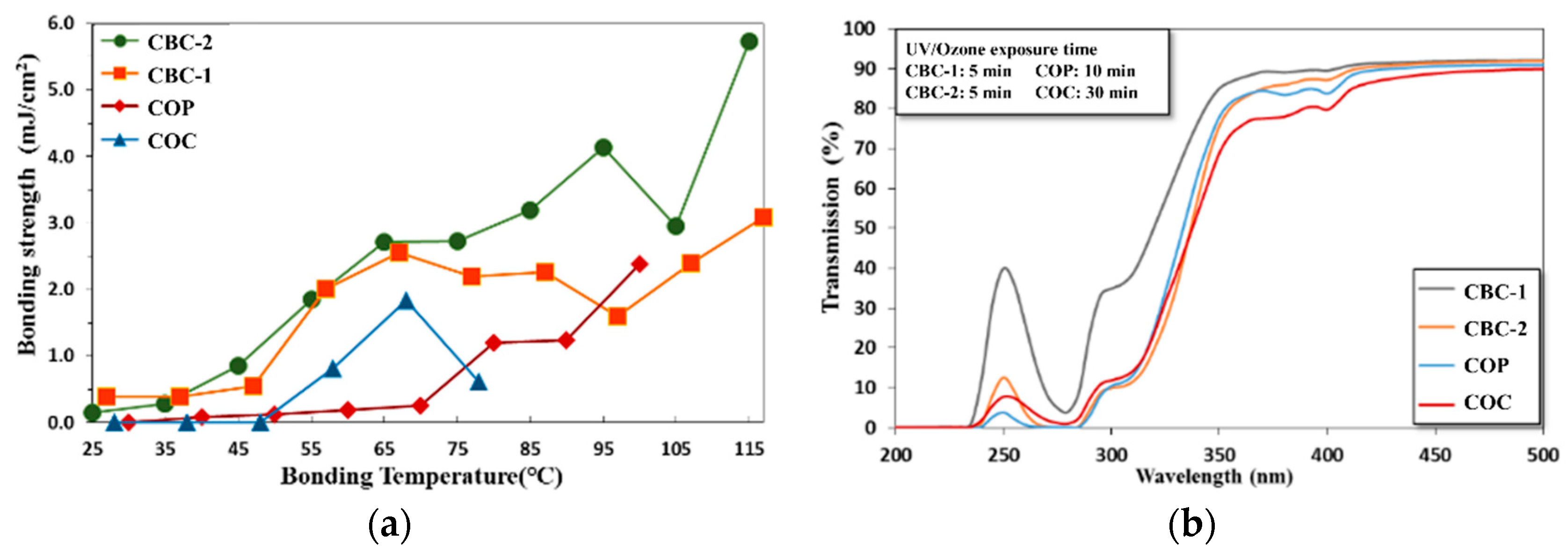
Figure 9.
Microchannel design and leakage test for the CBC thermoplastic microchannels with a blue food dye injection at 15 μL/min. Red-dashed box indicates microchannel images with blue food dye.
Figure 9.
Microchannel design and leakage test for the CBC thermoplastic microchannels with a blue food dye injection at 15 μL/min. Red-dashed box indicates microchannel images with blue food dye.


Table 1.
Thermal fusion bonding process parameters.
| Bonding pressure (kg/cm2) | 30 |
| Bonding time (min) | 20 |
| CBC-1 * Bonding temperature (°C) | 27/37/47/57/67/77/87/97/107/117 |
| CBC-2 Bonding temperature (°C) | 25/35/45/55/65/75/85/95/105/115 |
| COC * Bonding temperature (°C) | 28/38/48/58/68/78 |
| COP * Bonding temperature (°C) | 30/40/50/60/70/80/90/100 |
* CBC: Cyclic Block Copolymer, COC: Cyclic Olefin Copolymer, COP: Cyclic Olefin Polymer.
© 2018 by the authors. Licensee MDPI, Basel, Switzerland. This article is an open access article distributed under the terms and conditions of the Creative Commons Attribution (CC BY) license (http://creativecommons.org/licenses/by/4.0/).
Share and Cite
MDPI and ACS Style
Yen, C.-Y.; Chang, M.-C.O.; Shih, Z.-F.; Lien, Y.-H.; Tsao, C.-W. Cyclic Block Copolymer Microchannel Fabrication and Sealing for Microfluidics Applications. Inventions 2018, 3, 49. https://doi.org/10.3390/inventions3030049
AMA Style
Yen C-Y, Chang M-CO, Shih Z-F, Lien Y-H, Tsao C-W. Cyclic Block Copolymer Microchannel Fabrication and Sealing for Microfluidics Applications. Inventions. 2018; 3(3):49. https://doi.org/10.3390/inventions3030049
Chicago/Turabian StyleYen, Chia-Yi, Moh-Ching O. Chang, Zong-Fu Shih, Yi-Hsing Lien, and Chia-Wen Tsao. 2018. "Cyclic Block Copolymer Microchannel Fabrication and Sealing for Microfluidics Applications" Inventions 3, no. 3: 49. https://doi.org/10.3390/inventions3030049