Experimental Study of an Organic Rankine Cycle Using n-Hexane as the Working Fluid and a Radial Turbine Expander

Department of Mechanical Engineering, National Institute of Technology, Tiruchirappalli 620 015, India
*
Author to whom correspondence should be addressed.
Inventions 2018, 3(2), 31; https://doi.org/10.3390/inventions3020031
Submission received: 29 March 2018
/
Revised: 7 May 2018
/
Accepted: 15 May 2018
/
Published: 21 May 2018
(This article belongs to the Special Issue Heat Transfer and Its Innovative Applications)
Abstract
:Conversion of low-grade waste heat to electrical energy paves the way to reducing environmental pollution. This work focuses on the experimental study of an organic Rankine cycle (ORC) with an n-hexane working fluid and radial turbine expander. The heat source is varied from 120 to 190 °C with a mass flow rate of 0.10 to 0.50 kg/s and pressure between 12 and 15 bar. The heat-source temperature has a direct impact on turbine performance. Increase in the mass flow rate of the working fluid led to an increase in pressure and temperature at the turbine inlet. The rise in turbine speed enhanced electrical efficiency while cutting down isentropic efficiency. The optimum speed of the turbine increased with increasing in turbine inlet temperature. Superheating leads to an increase in power along with a decrease in isentropic efficiency. The thermal efficiency followed an increasing trend when there was an increase in turbine inlet temperature and mass flow rate and decreased with an increase in turbine speed. The electrical efficiency increased for all three cases. The system was found to have a highest thermal efficiency of 5.57% with a power of 1.75 kW. Based on the experimental results, it can be concluded that an ORC with n-hexane as the working fluid and a radial turbine as the expander can be used in low-temperature waste heat recovery systems to produce power.
1. Introduction
Renewable energy has immense importance in the energy sector as fossil fuels are vanishing from the Earth due to rapid industrial development. Nowadays, researchers are focused towards the development of alternative energy resources which can reduce dependence on nonrenewable resources. Energy consumption has increased many fold predominantly due to the progress in science and technology with a growing human population. Electricity produced from fossil fuels has low efficiency when equated with the aggregate of fuel and heat sources used. Waste heat from automobiles, industrial processes, and greenhouse gases are released into the atmosphere, which accelerates the degree of global warming. From this perspective, waste heat needs to be used effectively to produce power, which diminishes emissions and also leads to the preservation of fossil fuels.
The organic Rankine cycle (ORC) system has been proposed as an effective technology to recover heat from low-temperature sources; that is, biomass, solar, geothermal, and waste heat from power plants. The organic Rankine cycle works on the same principle of the steam Rankine cycle. The organic fluid is the heat carrier within the cycle, being better adjusted than water to low temperatures. The organic working fluid has a higher molecular mass and lower boiling point compared to water. The type of working fluid and the turbine used in the ORC system governs the efficiency of the overall system. A Rankine cycle with steam as the working fluid and at high temperature and pressure has an efficiency of 35–40%, whereas a Rankine cycle with organic working fluids at low temperature and pressure gives an efficiency of 8–12% [1]. ORCs have been found to be capable of absorbing the waste heat from various sources such as solar [1,2,3], biogas [4,5], geothermal [6,7], and other industrial processes. Many researchers have reported on different expanders for ORCs, such as the radial turbine [8,9,10], scroll expander [11,12], and screw expander [13,14].
A new design method to develop ORC radial turbines was described by [15], where the method does not deal with the ideal gas equation and average state equations. The results of CFD simulations showed that the incidence angle of rotor blades and speed of the rotor have great impacts on the efficiency and power output of the turbine. A comparative study on the off-design performance of a basic organic Rankine cycle and a dual-pressure organic Rankine cycle was conducted by [16], and it was found that the efficiency of the radial inflow turbine of both cycles was strongly influenced by the saturated condensing temperature and hot water inlet temperature. Computational design and analysis of a radial inflow turbine for an ORC was conducted by [17], and it was found that the turbine effectively handled the temperature dissimilarity with an efficiency drop of 1.53%. At higher temperatures and rotational speeds, the efficiency of the system increased, while efficiency progressively decreased with an increase in the pressure ratio. The superheating effect of the evaporator on the solidity of the ORC was studied by [18], where they found that the system efficiency remained constant and produced more electricity at lower superheat. Hydrofluoro olefins are the fourth-generation refrigerants, which are found to have low ozone depletion potential and global warming potential and can be used as the working fluid in low-temperature ORC systems. Working fluid selection for a combined solar Rankine cycle for RO desalination was done by [19], and it was found that hexane gave higher first- and second-law efficiencies compared to water and that this depends on the solar collector area, exergy destruction, and specific total cost. Thermodynamic evaluation of the working fluid on the design and performance of an ORC was done by [20], where they found that fluids having higher critical temperatures will give increased efficiency and also lead to higher expansion ratios. They concluded that fluorocarbons and low-critical-temperature hydrocarbons are the most suitable fluids for low-temperature applications, whereas siloxanes and hydrocarbons with a high critical temperature are promising fluid candidates for high-temperature ORC applications. Thermodynamic modeling and analysis of a solar ORC was done by [21], and it was found that hexane gave the highest collector efficiency of 59.19% and that cyclohexane showed high thermal efficiency and high net work output. The performance evaluation of a direct vapor generation supercritical ORC driven by a linear Fresnel reflector was done by [22], and it was found that fluids with high critical temperatures require lower mass flow rates in the system. They found that cyclohexane achieved the highest overall efficiency of 19.65%. A working fluid selection diagram was proposed by [23] for a parabolic trough and linear Fresnel collector-based Rankine cycle. They found that isohexane achieved a levelized cost of energy near to that of a parabolic trough collector-based steam Rankine cycle. Since the ORC works in a low-pressure range for smaller amounts of power production, a single-stage turbine is mostly used. A two-stage axial turbine was designed and its performance was compared with a single-stage turbine by [24], and the power output was found to be 16.04 kW for the two-stage turbine, whereas 11.06 kW was the output of the single-stage turbine. The efficiency was also increased from 10.5% for the single-stage turbine to 14.2% for the two-stage turbine. A generalized assessment of both optimal working fluids and radial turbine designs for a small-scale organic Rankine cycle was done by [25], using the Peng–Robinson equation of state to optimize the working fluid and cycle parameters in the temperature range of 80 to 360 °C. A correlation has been deduced which relates the heat source temperature to the critical temperature of the working fluid, which can be used to find the optimum working fluid for a given temperature. Using zeotropic mixtures of working fluids in an ORC will increase the performance of the ORC. A preliminary design guideline of zeotropic-mixture working fluids in ORCs was proposed by [26], where they found that the designed mixtures have better performance than pure working fluids. The SIMPLEX algorithm was used as an optimization tool to study the performance of ORCs by [27], with variable heat source flow rates and inlet temperatures to the evaporator, and it was found that at low strain of the evaporator, the turbocharger produced a variable output of 34.5 to 55.5 kW and this increased with increase in the temperature of the waste stream at the evaporator. A recent publication of the authors [28] lists the reviewed selection of working fluids and expanders for ORCs along with the applications of ORCs in various topping and bottoming cycles.
The previous research works on ORCs show that the performance of the system is always influenced by the operation parameters, working fluid, and performance of key equipment. Regarding the previous literature, an experimental investigation of an ORC using n-hexane for various operating conditions with a radial turbine expander has not been explored, which marks the novelty in the current work. Hexane is proven to be an effective working fluid for medium- and high-temperature organic Rankine cycles, whereas the usage of hexane in low-temperature ORCs has not gained major importance, and the main advantage of using hexane is that it requires low mass flow rates since the critical temperature is high (224 °C). The main novelty in the current work is varying the process parameters and thus improving the understanding of the influencing parameters on the efficiency of the overall system. So, the present study deals with the experimental study of an ORC with n-hexane as the working fluid and a radial turbine expander. Experiments are conducted for different working parameters of the heat source temperature, mass flow rate of the working fluid, turbine speed, coolant flow rate, and superheating process. The thermal and electrical efficiencies of the system for different working conditions are determined and are reported in the current article.
2. Description of the Organic Rankine Cycle System
The ORC relates the principles of a Rankine cycle using an organic fluid that has a low boiling point to recover heat from low-temperature heat sources. An ORC system consists of four main components, namely: (i) a working fluid pump; (ii) an evaporator; (iii) an organic expander; and (iv) a condenser.
Organic fluid is heated by the heat source at a constant subcritical pressure and leaves the evaporator as superheated or saturated vapor. Then, it expands to generate power in a polytropic process. During the condensation process, the exhaust vapors get cooled down at a constant pressure.
The organic Rankine cycle works with the same principle of a steam Rankine cycle, where an organic fluid is used to produce power at low temperature and pressure. The working fluid will be sucked by the diaphragm pump and pressurized to 12 bar, at which point the heat is supplied by means of constant heat flux at the heater. The fluid flow rate is controlled by a Coriolis flow meter, which acts as a two-phase flow meter. Once the saturated state is reached, the vapors will be passed through the turbine where the blades rotate and mechanical energy is produced. The turbine is connected with a generator, by which means the power is produced. In our experimental study, hexane is chosen as the working fluid. A diaphragm pump is used to increase the pressure of the working fluid to 12 bar. Constant heat flux is given to the heater by means of an autotransformer, which heats the pressurized working fluid. After reaching the steady state condition at 145 °C, the vapors are passed through the turbine. The working fluid vapors will rotate the turbine blades, and the turbine is connected to generator, where the electrical energy is produced and is stored in a battery.
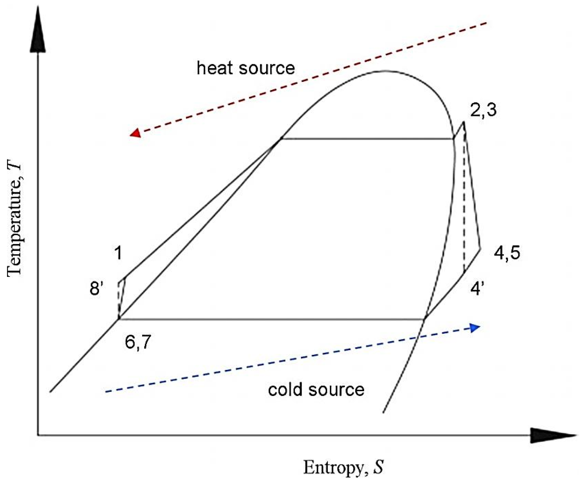
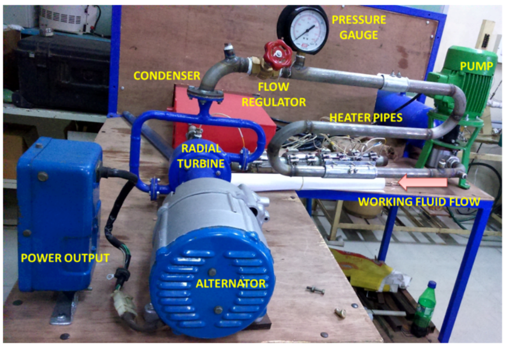
Figure 1 depicts the basic T–s chart of an ORC, and Figure 2 shows the ORC prototype specially designed for the current experimental study.
2.1. Working Fluid
The selection of the working fluid is essential for the efficiency of low-temperature organic Rankine cycles. Because of the low temperature, heat-transfer inefficiencies are highly harmful to the overall efficiency [29]. These inefficiencies depend very strongly on the thermodynamic characteristics of the fluid and the operating conditions. The operating fluid should be nontoxic and nonflammable; present low GWP (<1000), good availability, and low cost; and have thermodynamic properties offering high system efficiency (>0.4 = ideal efficiency). A superheater is employed to increase the dryness of the working fluid at the outlet of the turbine [30].
The working fluid should have high latent heat and high density. The critical points of the working fluid determine the working conditions of the ORC system. The high density will lead to an enhanced mass flow rate, which in turn, would shrink the pump work and increase the turbine output [29]. The corrosive nature should be low, and it must be compatible with the moving parts of the system. Hexane gas has been used in high- and medium-temperature ORCs, but not in low-temperature ORCs. Hence, hexane as a working fluid was studied in the ORC in the current study. Hexane is a flammable liquid with an autoignition temperature of 225 °C. It has to be used in a closed system with safety procedures. The compatibility and performance of an ORC with n-hexane (a straight-chain hydrocarbon) is investigated in the current study.
Based on all the operating conditions and the thermophysical properties of the working fluid in the ORC, n-hexane was decided upon as it is found to be chemically stable and the critical temperature favors the application in low-temperature waste heat recovery. Hexane is an acyclic straight-chain hydrocarbon consisting of only carbon and hydrogen atoms, with the chemical formula C6H14. It exhibits low reactivity compared to other hydrocarbons. The thermal and physical properties of the working fluid are listed in Table 1.
2.2. Turbine and Generator
The overall performance of an ORC mainly depends on the type of turbine used and the working fluid employed. If the working fluid’s pressure and temperature are high, subsequently the steam velocity will be high, and in this case, the turbine employed should be a double-stage turbine. In this work, the working temperature and pressure are low, so a single-stage turbine is employed. The radial inflow turbine has the advantages of large enthalpy drop in a single stage with high overall efficiency. The fabricated turbine is presumed to give a power output of 2.2 kW, and the exit operating constraints are varied depending on the power to be produced. Magnetic coupling is used to connect the turbine to an AC generator which has an output of 2.5 kW with a rating of 3 kW. The generator is capable of giving an output of 120 V-AC power supply at nominal working conditions.
2.3. Design and Analysis of Radial Turbine
The initial design of the turbine is done based on the thermophysical properties of the working fluid and the working parameters of the experimental setup. The initial design parameters of the turbine are listed in Table 2. The rotor of a centrifugal pump is dismantled, and a separate casing is designed. The blade angles and other parameters of the rotor are modified to match with the predetermined operating conditions. The turbine consists of an inward flow volute, impeller, and deflector. In our case of a radial inflow turbine, not all the nozzles were operated at the same time. During observation, if we found any loss in pressure or temperature at the inlet of the turbine, then the secondary nozzle would be opened. If there was no fluctuation of temperature and pressure, the turbine would be operated with a single nozzle. The nozzle functioning enables the turbine to tolerate the fluctuating temperature and pressure. Since the system is functioning at low temperature and pressure, the turbine is designed to tolerate the fluctuating heat source and pressure. The inlet and outlet blade angle of the rotor are 45 degrees and 10 degrees, respectively. It has a 45-degree angle at the midspan. The blade height at the inlet and outlet are 65 cm and 35 cm, respectively.
Based on the initial design parameters, the turbine is developed from a centrifugal compressor and the outcomes of this are listed in Table 3.
The redesigned centrifugal compressor is made to act as the turbine, and it is worked in the mediums of air and water, the results of which are mentioned in Table 4. We were able to find that the so-designed radial turbine is compatible with the fluctuating load in the heat source and the flow rate of the working fluid.
Since the blade is made of aluminum, it has the advantages of easy machining and being lightweight. The turbine is connected with the generator through magnetic coupling without any speed reduction gearbox so that the rotor can run at higher speeds in normal working conditions. Since the ORC is operated at low temperature and pressure, the chance of expansion of the turbine material and outer casing is very low, and so it is neglected. Regarding the structural integrity, the redesigned turbine was operated at up to a temperature of 260 °C with pressure of nearly 15 bar and turbine speed close to 50,000 rpm. After the observations, the parts of turbine were dismantled to check for possible breakages. We found that the turbine was break-free, and this can also be confirmed with the result that was obtained during its operation.
2.4. Evaporator System
The fluid is heated in the evaporator, and a phase change occurs from compressed liquid to saturated vapor. The evaporator used in the ORC system is a MS tube of 3.81-cm diameter which has three rounds, and on the periphery of the tube, heaters of 1200 W are connected, and the power is given by means of an autotransformer which is used to give constant heat flux to the heaters. Low heat is given for low flow rates, and vice versa, which increases the temperature of the working fluid in a short period. The heater input is configured in such a way that the working fluid is always in the saturated vapor state at the turbine inlet.
In the case of indirect heating of the working fluid, a container with a band-type heater at the peripheral layer is employed. It heats Therminol 55, which is used as the heat-transfer fluid and is sent to the shell and tube heat exchanger, where the working fluid flows in tubes and absorbs the heat from the heat-transfer fluid and reaches the turbine.
2.5. Selection of Pump
Selection of the pump for a small-scale ORC is a difficult task, owing to the varying input conditions. In our system, since the mass flow rate is low, easily accessible centrifugal pumps cannot be operated. The diaphragm pump is employed to maintain the required pressure. The pump is capable of giving pressure of up to 40 bar with a mass flow rate of 15 L/min. The main advantage of the diaphragm pump is that it can work in all pressure ranges with self-priming capabilities and a lubrication-free arrangement. The power consumption of the pump is calculated by measuring the values of voltage and current. The pump efficiency is calculated by the thermodynamic properties of the working fluid at the pump inlet and outlet.
2.6. Cooling System
The cooling system employed is a shell and tube heat exchanger using water as the working fluid. Normal water at a temperature of 28 °C is drawn from a reservoir at the top of the building and is given to the condenser. The turbine outlet is connected at the inlet to the condenser, and the condensation temperature was found to be around 35–40 °C in both the cases of heating. The condenser is designed to work with higher capacity than in steady-state conditions, and this is done to maintain stable condenser conditions.
3. Experimental Setup
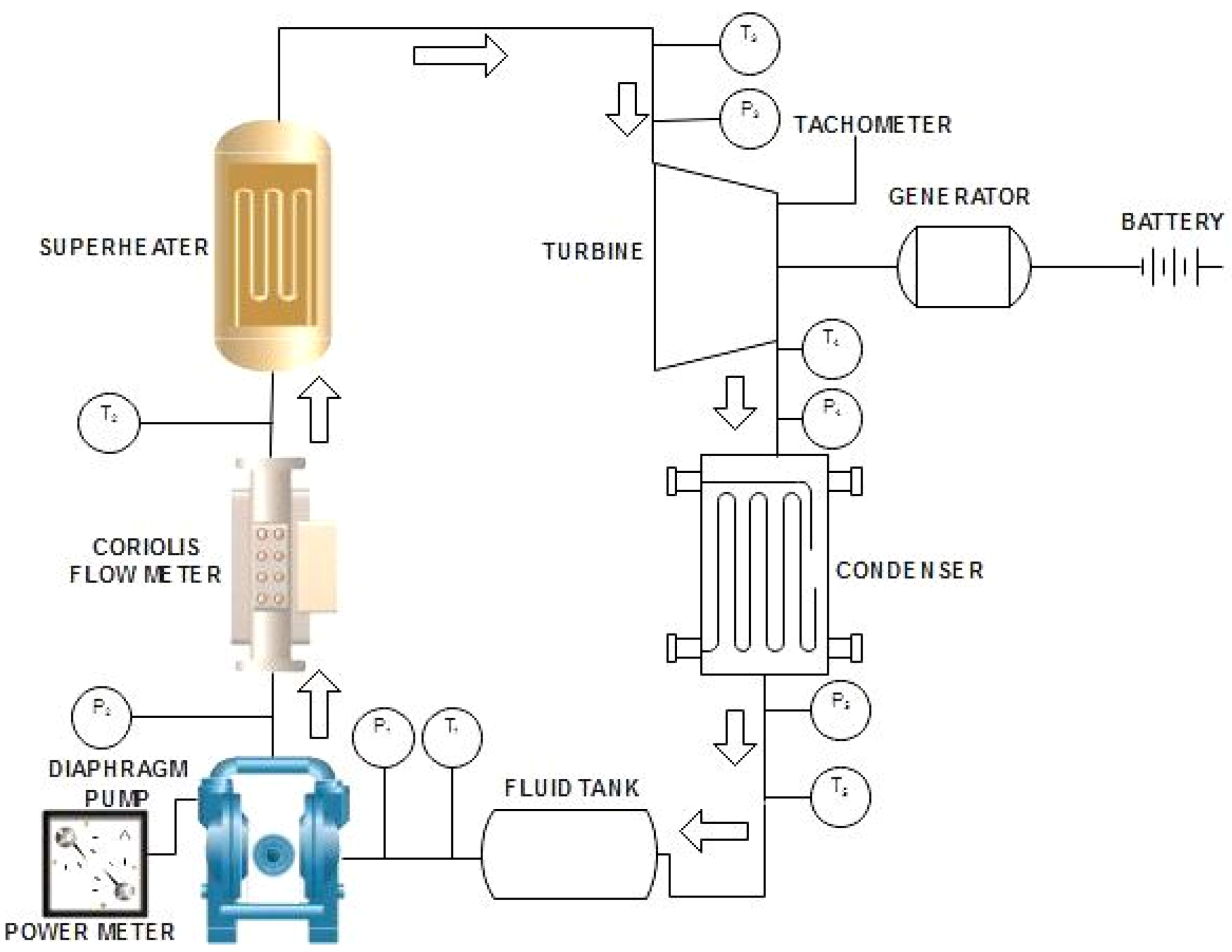
The temperature at the evaporator inlet and exit and expander inlet and outlet are measured using T-type thermocouples which are brazed to the inner diameter of the tubes. The thermocouples are connected to a data logger, and the temperature data is recorded every 120 s. Pressure is measured via a pressure gauge which is employed between the pump and evaporator and at the outlet of the condenser. The rotational speed of the turbine is measured by a tachometer. The working fluid flow rate is controlled and monitored by means of a Coriolis flow meter, which is a Siagro make and model MF5706-N-25-B-O, which works in the flow range of 0–25 SLPM and has an accuracy of ±2% with turn-down ratio of 30:1. The Coriolis flow meter is connected between the evaporator outlet and turbine inlet, where the flow rate of the working fluid is controlled and monitored. A single two-phase generator is connected to the turbine, using which output voltage and current are calculated. Figure 3 depicts the flow diagram of the ORC prototype used in the current study.
Uncertainty Measurements
An uncertainty analysis was carried out based on the commonly used expression:
Δ refers to the uncertainty in the measured value. Y represents the variable in the function and X represents the constant function in the measurement.
The measuring devices’ uncertainties obtained from the manufacturers’ data sheets as well as the uncertainties for key cycle parameters obtained by Equation (1) are shown in Table 5.
4. Thermodynamic Analysis of the Organic Rankine Cycle
For the thermodynamic analysis, some assumptions are made which are as follows: All the components of the system are considered as steady-state flow devices. The pressure drops in the condenser, evaporator, pipes, and tubes are neglected along with the heat losses in the components. Isentropic efficiencies of the turbine and pump are given. The working fluid enters the pump as a saturated liquid.
Pump power (Wp) is calculated by
where qm is the mass flow rate of the working fluid in kg/s, and h7 and h8 are the enthalpies at the pump inlet and outlet in kJ/kg, respectively, corresponding to the pressure at the pump inlet and outlet, respectively.
Wp = qm (h8 − h7)
Heat transfer in the evaporator is given by
where h1 and h2 are the enthalpy values (kJ/kg) of the working fluid at the evaporator inlet and outlet, respectively.
Q21 = qm (h2 − h1)
The condenser heat release rate is given by
where h5 and h6 are the enthalpy values (kJ/kg) of the working fluid at the condenser inlet and outlet, respectively.
Q56 = qm (h5 − h6)
The output power from the turbine is given by
where h3 and h4 are the enthalpy values (kJ/kg) of the working fluid at the turbine inlet and outlet, respectively.
Wt = qm (h3 − h4)
The isentropic expansion power of the turbine is given by
where h4s is the isentropic enthalpy of the working fluid at the turbine outlet.
WT,S = qm (h3 − h4s)
The isentropic efficiency (ŋs) is defined as the ratio of the actual expansion power acquired from the turbine to the isentropic expansion power that can be acquired from the turbine.
ŋs = WT/WT,S = (h3 − h4)/(h3 − h4s)
The electromechanical efficiency (ŋm) is the key indicator of the system performance and is defined as the ratio of generator power output to work done by the turbine.
ŋm = Pe/WT = Pe/(qm (h3 − h4))
The thermal efficiency (ŋt) is defined as the ratio of the turbine work output to the heat absorbed by the working fluid in the evaporator. In other words, the thermal efficiency is the ratio of the area bounded by the cycle in the T–s diagram to the area under the heat addition process.
ŋt = (WT − WP)/Q21 = ((h3 − h4) − (h8 − h7))/(h2 − h1)
5. Testing Conditions of the ORC
Performance studies are carried out with varying mass flow rate, heat source temperature, and rotational speed of the turbine. The heat source temperature is varied from 120 to 190 °C. The working fluid flow rate is varied in the range of 0.10 to 0.50 kg/s. For a given heat source temperature and fluid flow rate, the turbine speed is varied. To study the effect of the coolant on the heat source, the flow rate of the cooling medium is also varied.
To study the performance of the ORC with n-hexane as the working fluid, the experimental setup is operated in two different cases of heating the working fluid. In both the cases, once the system reaches the steady state, measurements are taken.
Case 1: Direct Heating: In this case, the working fluid is directly heated using an auxiliary heater with a capacity of 1200 W. The heater coils are wound around the tube which carries the pressurized working fluid from the pump. The heat transfer losses are minimized to a certain level while heating the working fluid. The fluid temperature did not fluctuate, since a constant supply heat is given through the heater. The temperature is varied from 120 to 190 °C after reaching the steady-state conditions.
Case 2: Indirect Heating: The working fluid is indirectly heated using a heat transfer loop. It consists of a heater, where the heat transfer fluid (Therminol 55) is heated, and the oil is passed through the shell side of the heat exchanger, where it rejects the heat to the working fluid flowing in the tube side. In this case, we were able to find many losses occurring between the heat transfer fluid and the working fluid. The heat exchanger and working fluid loops are connected using a pump, which is used to pump the heated heat transfer fluid to the heat exchanger. The time taken to reach the steady-state condition was found to be longer compared to the direct heating condition. This is mainly due to the loss occurred between heating and pumping the heat transfer fluid to the heat exchanger.
6. Results and Discussion
The pump is operated to attain the steady-state conditions. The speed of the pump is varied to attain the required pressure from the pump to the evaporator. Appropriate time is left for the working fluid to get heated to a saturated state, and then the turbine inlet valve is opened steadily. Steady-state conditions are maintained for different working conditions. The electrical power produced from the generator is monitored from time to time, and the operating conditions are altered to get a continuous steady output from the generator. Experiments are conducted when the pump is functioning above 12 bar with an evaporator outlet temperature of more than 120 °C. Table 6 shows the temperature and pressure at various components of the system while delivering a 1.5-kW output.
6.1. Heat Source Temperature
The turbine performance is directly related to the temperature of the heat source. The turbine inlet temperature relies on the evaporator outlet temperature, which is interconnected with the heat source temperature [30]. It can be seen that as the heat source temperature increases, the working fluid temperature also increases, which in turn, increases the turbine inlet temperature.
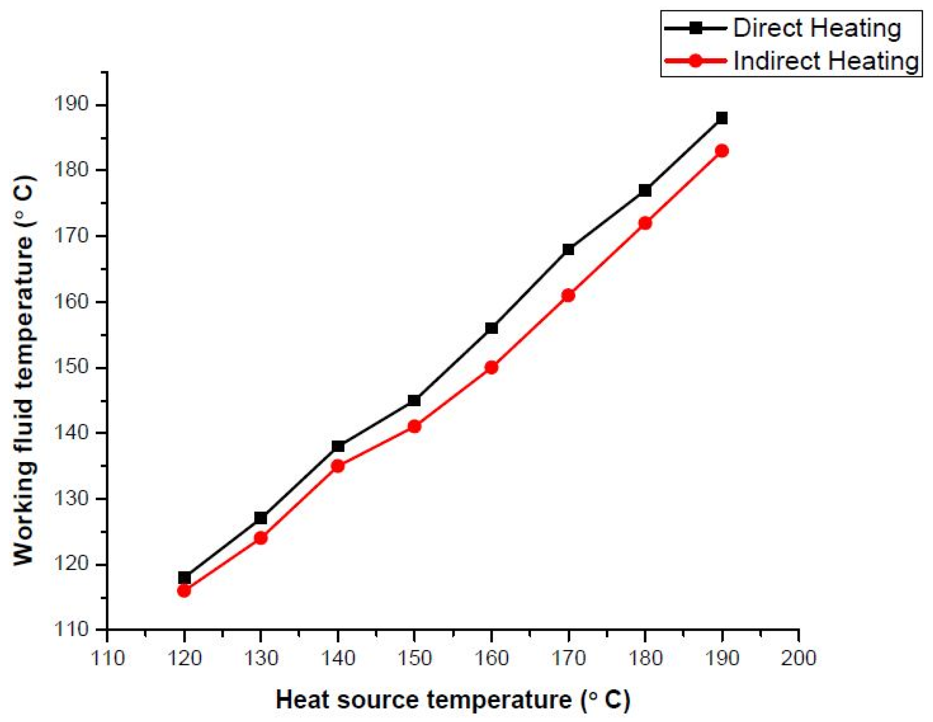
Figure 4 shows the variation of the working fluid temperature with heat source temperature in two different cases. It can be seen that the heat source temperature has a direct impact on the temperature at the turbine inlet [30] and in turn, on the turbine efficiency. For direct heating, the heat source and working fluid temperatures are nearly the same, whereas for indirect heating using a heat transfer fluid, the temperature deviations were found to be fluctuating for different heat source temperatures, which is mainly attributed to the heat loss between the working fluid and heat transfer fluid. The enthalpy drop was also observed due to the temperature drop in the working fluid. With an increase in the inlet temperature at the entry to the turbine, there was a minor increase in the pressure at the turbine inlet. The temperature at the turbine outlet also depends on the heat source temperature and turbine inlet temperature [26]. The expansion process is also affected by the heat source temperature, owing to the temperature at the inlet and outlet of the turbine. As the heat source temperature increases, the pressure at the turbine inlet increases.
6.2. Fluid Flow Rate
The flow rate of the working fluid affects the turbine temperatures. For higher flow rates, the temperature was found to drop at the turbine outlet [22]. For a higher mass flow rate, there is a chance for the turbine to become damaged. The fluid flow rate of the working fluid is varied by adjusting the pump valve. The turbine inlet temperature and pressure were found to increase with an increase in the mass flow rate. From our observations, it was found that as the mass flow rate is increased for a constant temperature at the turbine inlet, the enthalpy difference is also increased, which leads to increased efficiency. If the temperature is increased, then the efficiency showed a reducing trend.
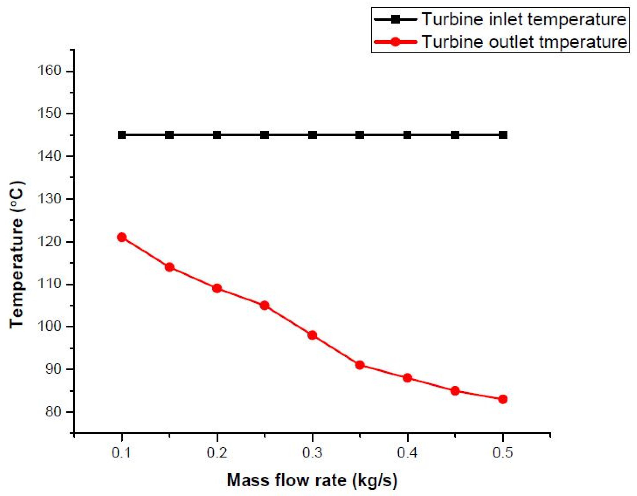
To study the effect of the mass flow rate on the isentropic efficiency of the turbine, the flow rate is varied from 0.10 to 0.50 kg/s, keeping the temperature constant at 145 °C. Figure 5 shows the temperature difference at the turbine outlet for a constant inlet condition and varying the mass flow rate of the working fluid. It can be seen from Figure 4 that the turbine outlet temperature decreases with an increase in the flow rate of the working fluid. This is mainly due to increase in the velocity of the vapor present inside the turbine, which in turn, reduces the temperature and pressure at the turbine outlet. Due to the large temperature drop in the turbine, the turbine efficiency was found to be high for the constant temperature at the inlet. The turbine is operated at the optimum speed of the turbine at the temperature of 145 °C, which is 45,007 rpm. If the mass flow rate is kept constant and the temperature is varied, then the efficiency decreased due to change in temperature at the turbine inlet. As the turbine efficiency increases, we were able to get an increased overall thermal efficiency for the ORC system.
As the mass flow rate is varied, the pressure at the turbine inlet also varied. This will reduce the pump work if the pump is operated at a low frequency. The system was initially operated in a steady state with an inlet pressure of the turbine of 12 bar. Figure 6 shows the variation of the turbine inlet pressure with change in the mass flow rate of the working fluid. With the increase in the flow rate of the working fluid, we were able to find a slight increase in the inlet pressure of the turbine. As the flow rate varies from 0.1 to 0.5 kg/s, the pressure increased from 12 to 15 bar at the turbine inlet.
6.3. Turbine Speed
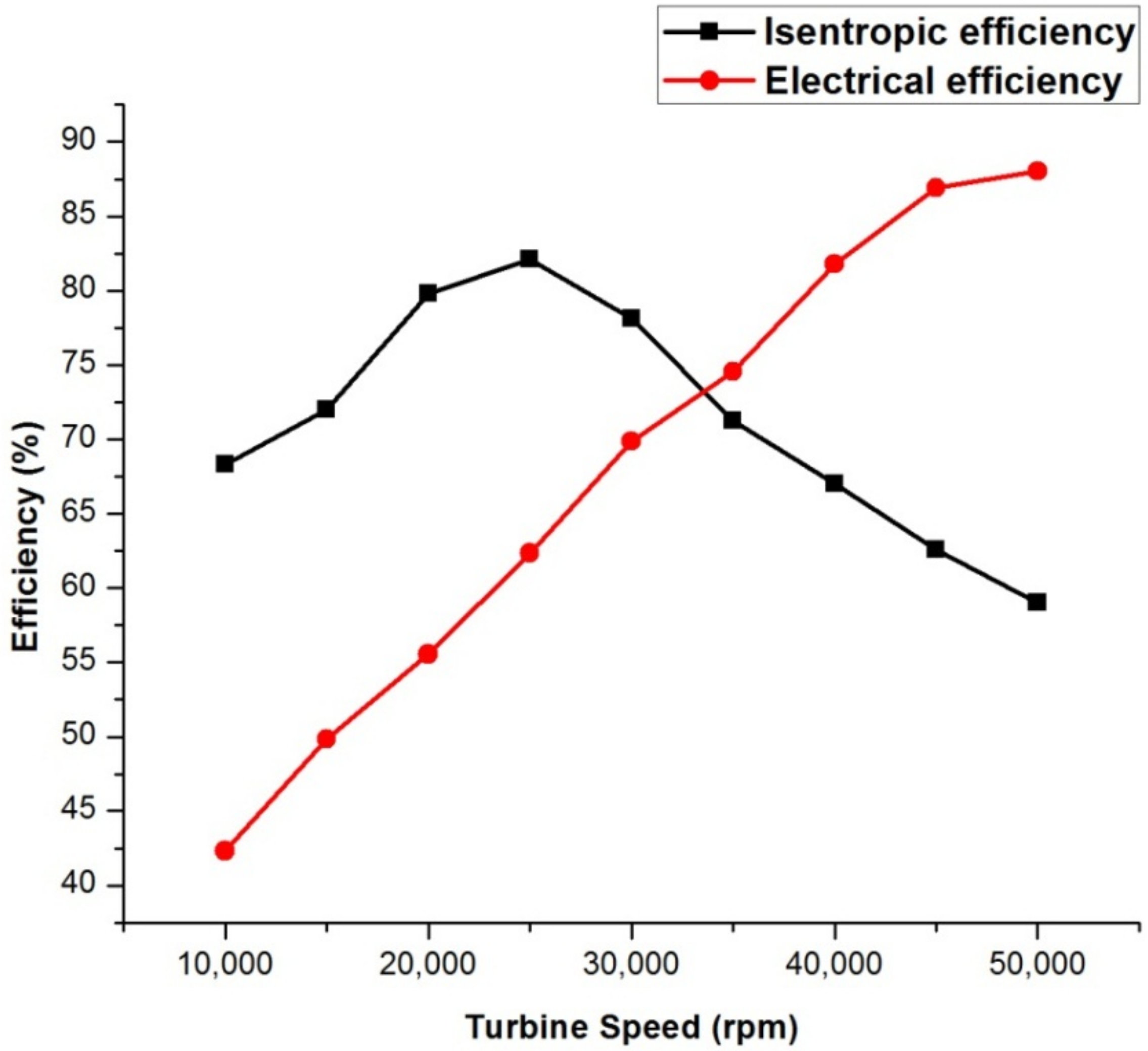
Figure 7 depicts the variation in turbine speed with isentropic and electrical efficiency. The enthalpy drop was found to be low, while the temperature dropped drastically. The enthalpy drop is attributed to the isentropic efficiency of the turbine. We found that as the speed of turbine increases after reaching 45,000 rpm, the isentropic efficiency was found to be lower. So, the maximum speed of the designed turbine is found to be not more than 45,000 rpm at a turbine inlet temperature of 145 °C with a mass flow rate of 0.45 kg/s.
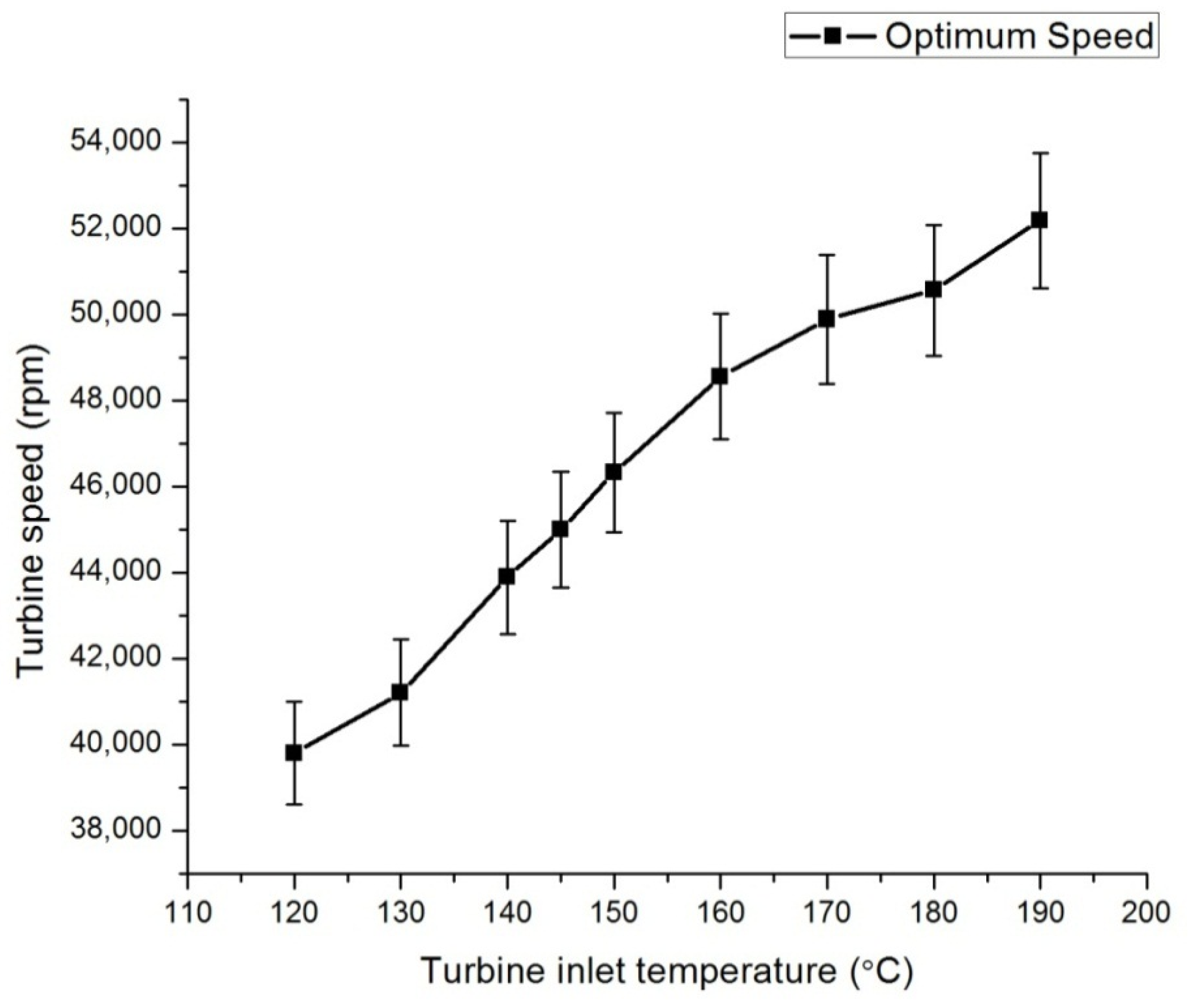
Another notable result we observed is that as the turbine speed is increased, the isentropic efficiency decreased and the electrical efficiency increased. This is applicable in places where high power is needed, irrespective of the turbine isentropic efficiency. The increase in the electrical efficiency is mainly due to the generator, which is coupled with the turbine running at high speed. Figure 8 shows the variation of the optimum turbine speed on the turbine inlet temperature, where the electrical efficiency was found to be 42% at a speed of 10,000 rpm, and it increased to 88% at a speed of 50,000 rpm. To study the impact of the efficiency of the turbine, the inlet conditions are kept constant with a mass flow rate of 0.45 kg/s and temperature of 145 °C.
The turbine rotational speed determines the isentropic efficiency across the turbine. The isentropic efficiency initially increases with the rotational speed; however, with further increase in the rotational speed, the isentropic efficiency drops after reaching a maximum value. So, the mass flow rate of the working fluid is changed to determine the optimum speed of the turbine, above which if the turbine is operated, the efficiency will drop, which leads to increased efficiency. When the turbine is operated above the optimum speed, the output from the turbine will automatically rise. However, in that case, there is a chance for the turbine to experience some damage. So, in order to avoid this and also to increase the lifetime of the turbine, the turbine is operated at its optimum speed, with an increase in the mass flow rate of the working fluid. It was found that the optimum speed of the turbine varies with a change in the turbine inlet temperature and mass flow rate of the working fluid. Turbine speed was found to increase as the temperature at the turbine inlet is increased. For the inlet temperature of 120 °C, the optimum speed was found to be 39,802 rpm; and when the temperature is 190 °C, the optimum speed was found to be 52,189 rpm. From these results, we can understand that the speed of the turbine has a major influence on the system efficiency, irrespective of the turbine inlet and outlet conditions.
6.4. Coolant Flow Rate
In our work, the coolant medium used is water, and the coolant rate was varied from 2.5 to 5 kg/s. The condenser temperature dropped rapidly at an increased flow rate. For our experimental work, the temperature at the condenser inlet was assumed to be constant, to study the effect of the coolant flow rate on the condenser work.
Figure 9 shows the variation of the condenser temperature and turbine power with the coolant flow rate. We found that, as the flow rate of the coolant medium is increased at the condenser, the temperature drops drastically, which is mainly due to the presence of an enormous amount of coolant at the condenser. Another interesting observation is that as the flow rate of coolant is increased, the turbine power is also increased. When the mass flow rate is varied from 2.50 to 5.0 kg/s, the temperature dropped from 98 to 32 °C. The observations were carried out at a temperature of 98 °C at the turbine outlet.
6.5. Effect of Superheating
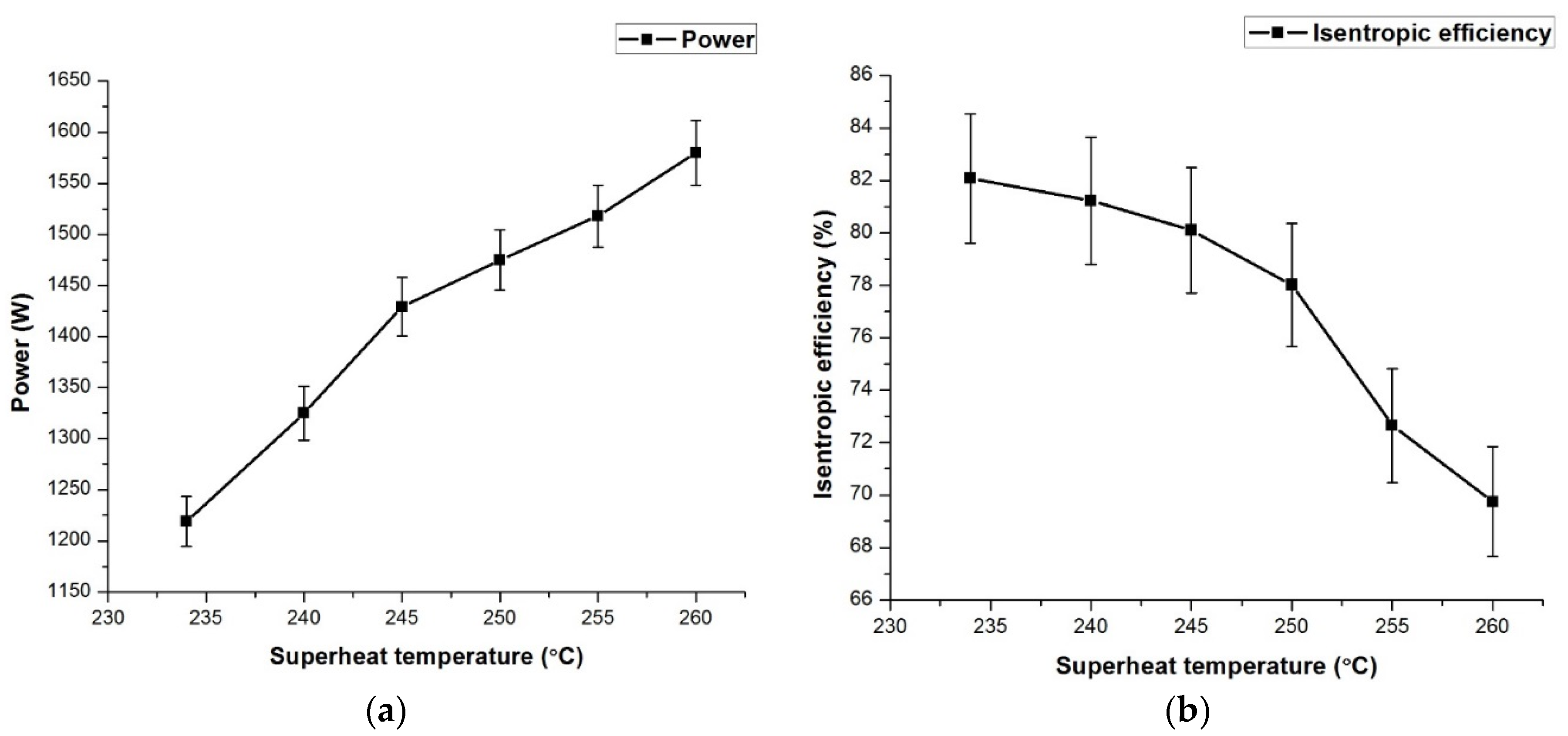
A superheater is mandatory for the Rankine cycle which uses water as the working fluid to avoid any decrease in the steam quality, since it is a wet fluid. A superheat cycle can be used to avoid the presence of liquid entrainment inside the turbine, thus increasing efficiency [18]. When superheating increases, the vapor density will decline, leading to the reduction of the mass flow rate and the pressure ratio across the expander. Meanwhile, an ORC which uses a dry fluid has no need of a superheater, because the saturated vapor curve in the T–s diagram has a positive slope. There is a chance for the efficiency of the system to be decreased due to the presence of a superheater [22]. The critical temperature and pressure of n-hexane are 234.5 °C and 30.2 bar, respectively. In steady-state conditions, the working fluid is heated between 120 and 190 °C, whereas in our case for a superheated state, only the temperature was raised, to 234 °C, irrespective of pressure. The pressure was maintained at 15.2 bar at the turbine inlet. From many experiments, it was observed that the superheating condition produces more power with very low efficiency [18]. So, the ORC is much better-suited to work in saturated conditions than in superheated conditions, owing to the decrease in the efficiency of the system. We conclude that superheating is necessary only for wet fluids such as water, whereas for a dry fluid such as n-hexane, it can be avoided. For the supercritical condition, the expansion efficiency was found to be low. Figure 10 shows the variation of isentropic efficiency and power with superheated temperature. The designed ORC was operated at superheated conditions in the temperature range of 230 to 260 °C, and the isentropic efficiency was found to be 82.08% for a subcritical condition and 69.75% for a supercritical condition, which is mainly due to a reduction in expander efficiency.
6.6. Power Produced and Thermal Efficiency
The proposed system was designed to produce a power output of 2.5 kW. We were able to get a maximum power output of 2.31 kW, varying down to 1.75 kW, depending on the working conditions. For a constant temperature at the turbine inlet, we got a nearly constant power output. The thermal efficiency varied depending on the temperature at the turbine outlet and condenser temperatures.
As already observed, as the mass flow rate increases, it can change the temperature and pressure at the turbine inlet. This led to a change in the power and thermal efficiency of the system. We observed that for an increased flow rate of the working fluid, the temperature at the turbine outlet reduced, which led to an increase in isentropic efficiency, and the thermal efficiency was also found to increase. Due to an increase in the mass flow rate, the power output also increased, owing to the increase in the pressure at the turbine and increase in thermal efficiency.
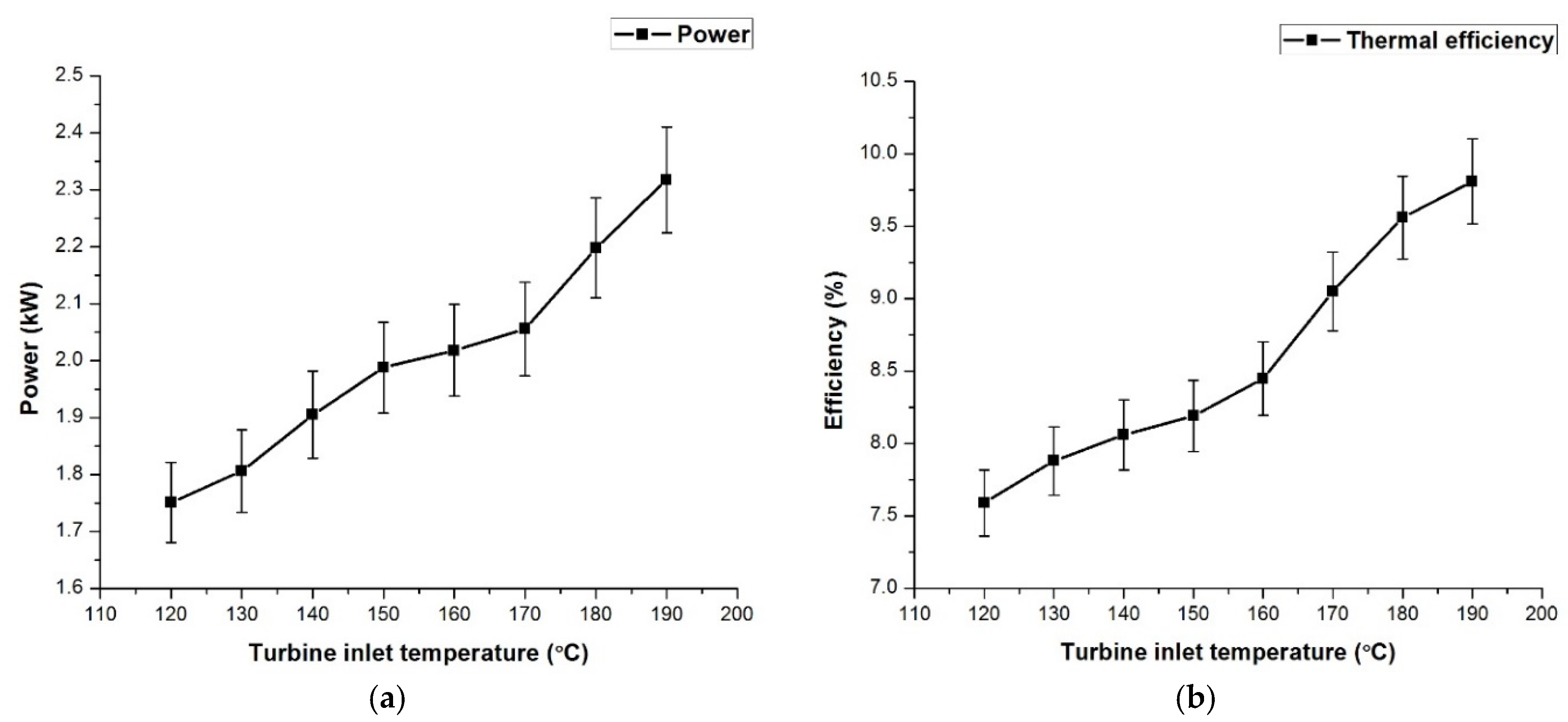
Figure 11 shows the variation of power produced and thermal efficiency with change in the turbine inlet temperature. We were able to find that as the turbine inlet temperature is increased, the thermal efficiency and power produced increased, which can be attributed to the increase in the work done by the system.
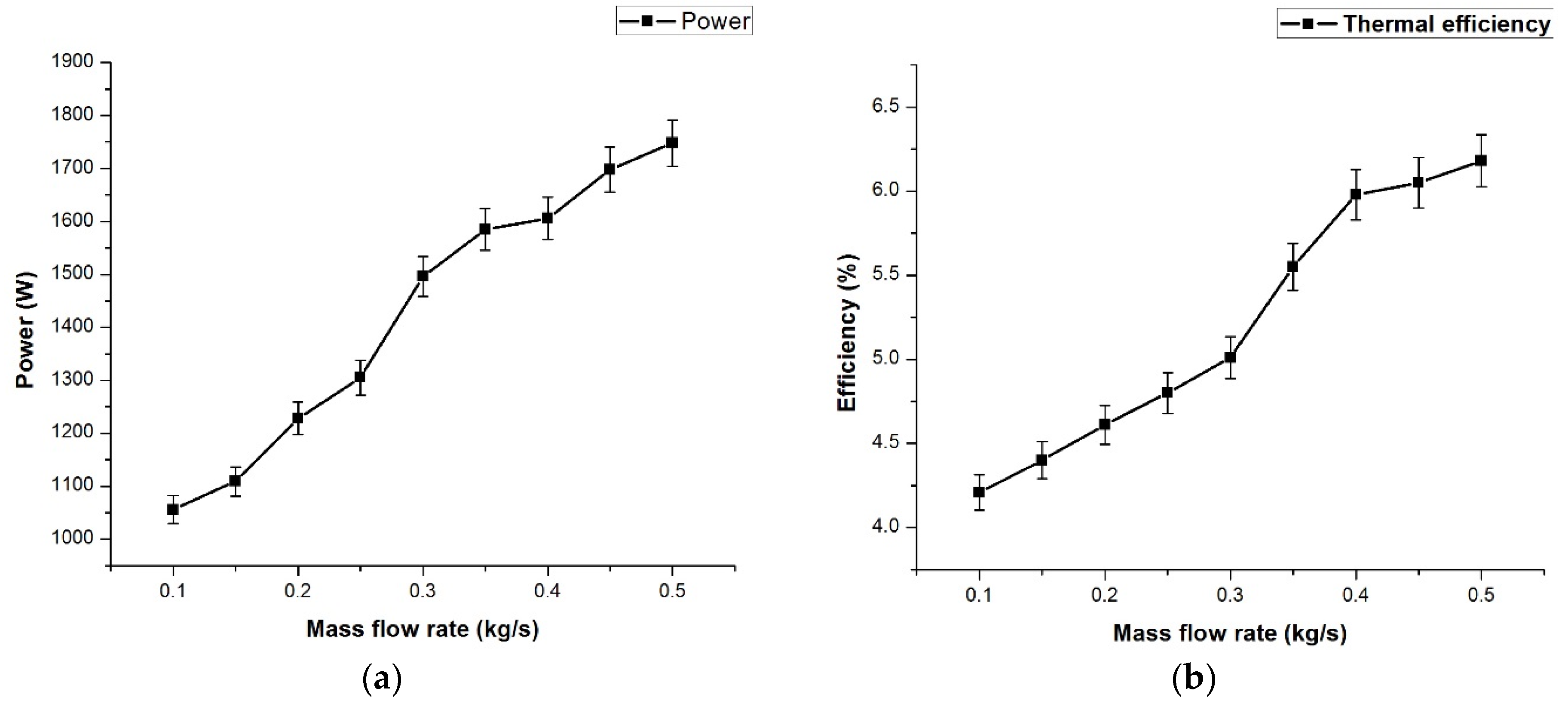
Figure 12 shows the change in power produced and thermal efficiency of the system with change in the mass flow rate of the working fluid. We can observe that the power and thermal efficiency increased with increase in the mass flow rate of the working fluid, which is mainly due to a larger amount of working fluid which is sent to the turbine to perform work and which also improves the temperature difference at the turbine inlet and outlet. Due to the change in temperature and pressure at the turbine inlet and outlet, the efficiency of the system automatically increases.
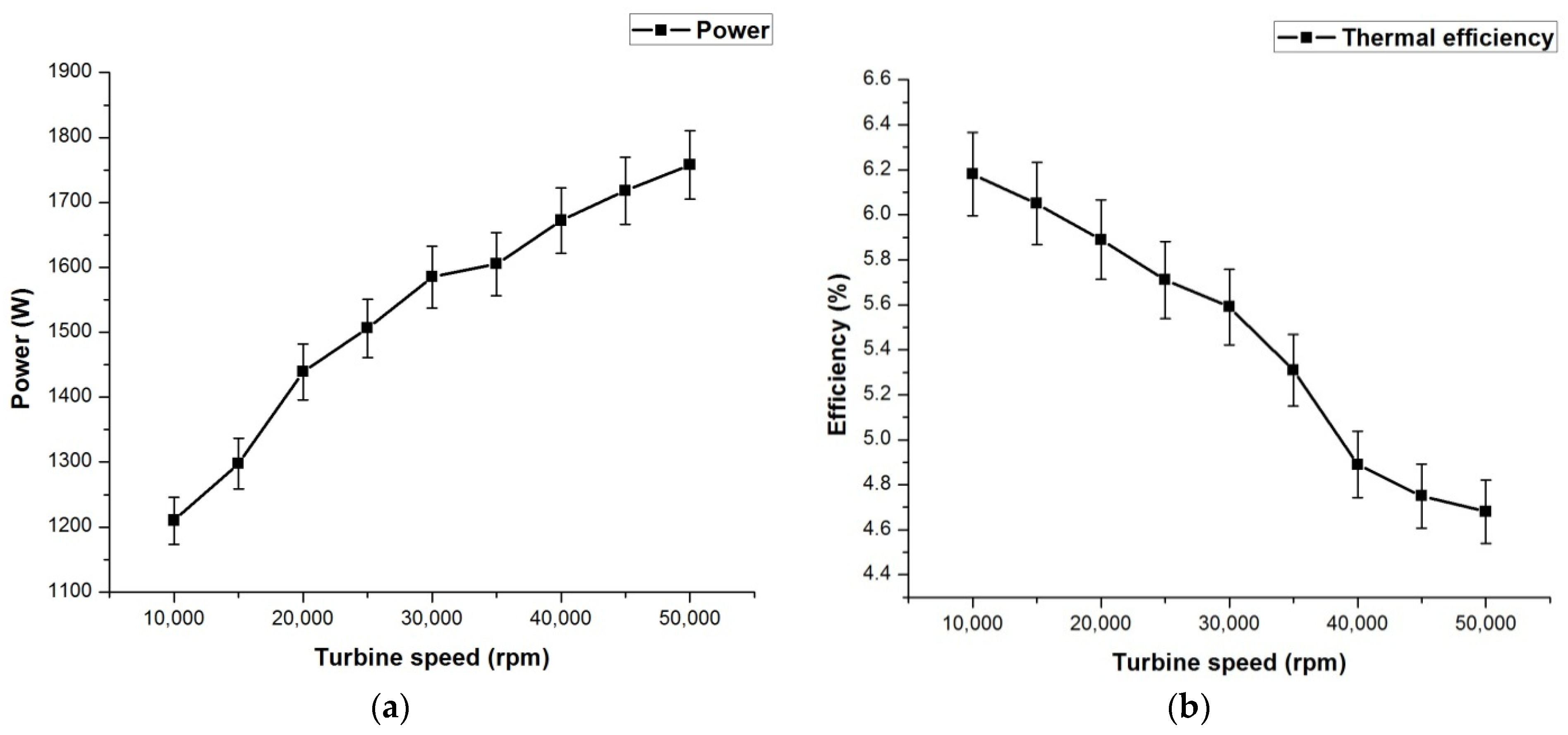
Figure 13 depicts the variation of power produced and thermal efficiency with the rotational speed of the turbine. We observed that as the turbine speed is increased, the power produced also increased, due to the alternator which is coupled with the turbine rotating at higher speed. On the contrary, the thermal efficiency gets reduced, which is mainly due to the temperature difference at the turbine inlet and outlet, which was found to be high.
6.7. Isentropic Velocity Ratio
The isentropic velocity ratio is the ratio of the blade velocity of the turbine to the isentropic gas velocity during its isentropic expansion on the turbine. The blade velocity ratio determines the maximum speed at which the turbine can be operated in a given number of stages. If the velocity is high for a given flow rate and temperature, the stage in the expansion has to be increased, which leads to reduction in speed in both the stages, but has an increased efficiency. In our observations, we found that the design of a single-stage radial turbine is optimum for the given pressure and temperature limits. Figure 14 depicts the variation of the isentropic efficiency with the isentropic velocity ratio and turbine speed. We found that the isentropic velocity ratio increased from 52.35 to 261.75 when the turbine speed is varied from 10,000 to 50,000 rpm, whereas the isentropic efficiency increased until 25,000 rpm and reduced after that speed was reached. The isentropic efficiency decreased after a certain speed, due to the fact that less time is given to the working fluid to expand in the turbine, which led to an efficiency drop.
7. Conclusions
An experimental study of an organic Rankine cycle with n-hexane as the working fluid and a radial turbine as the expander was investigated in this study. The rotor of a centrifugal compressor was redesigned to run as the turbine. The observations from our experimental study are:
- The heat source temperature played a major role in the maintaining the temperature at the turbine inlet. The heat source temperature was varied from 120 to 190 °C, and the working fluid temperature varied from 118 to 188 °C for direct heating and from 116 to 183 °C for indirect heating.
- As the mass flow rate of working fluid was increased from 0.10 to 0.50 kg/s, the turbine outlet temperature reduced from 121 to 83 °C and the pressure at the turbine inlet increased from 12 to 15.08 bar.
- The turbine rotational speed was varied from 10,000 to 50,000 rpm, and the isentropic efficiency of the turbine reduced from 68.32% to 58.98% and its electrical efficiency increased from 42.33% to 88.05%.
- The optimum turbine speed varied from 39,802 to 52,189 rpm, depending on the temperature at the turbine inlet.
- When the flow rate of the coolant was varied from 2.50 to 5.00 kg/s, the turbine power increased from 1009 to 1758 W and the condenser outlet temperature drastically reduced from 98 to 32 °C.
- For the superheat temperature of 260 °C, the power developed was found to be 1580 W, with an isentropic efficiency of 69.75% for the turbine.
- Thermal efficiency and power developed were found to increase from 4.52% to 6.21% and 1086 to 1750 W, respectively, when the heat source temperature was varied from 120 to 190 °C.
- With a change in the mass flow rate of the working fluid from 0.10 to 0.50 kg/s, the thermal efficiency and power developed were found to be increased from 4.21% to 6.18% and from 1056 to 1748 W, respectively.
- When the turbine speed was varied from 1000 to 5000 rpm, the thermal efficiency decreased from 6.18% to 4.68% and the power developed increased from 1210 to 1758 W.
- The efficiency of the current ORC system was found to be 5.57%, with a power of 1.75 kW.
With n-hexane as the working fluid, it can be concluded that the present ORC system is highly suitable for low- and medium-temperature waste heat recovery systems to produce power. The studied organic Rankine cycle assembly can be coupled with a solar desalination system to produce water and power using solar energy as a heat source.
Author Contributions
V.P. and S.S. conceived and designed the prototype of ORC. V.P. performed the experiment. Both the authors analyzed the data from the experiments. V.P. wrote the paper and S.S. corrected the same to make it possible manuscript.
Acknowledgments
The authors wish to thank the Department of Science and Technology (DST Sanction letter No. DST/TM/SERI/DSS/275(G), dated 9 September 2015), Government of India, for its financial support to this work.
Conflicts of Interest
The authors declare no conflict of interest.
Abbreviations and Symbols
| ORC | Organic Rankine cycle |
| HFO | Hydrofluoro olefin |
| LNG | Liquefied natural gas |
| GWP | Global warming potential |
| AC | Alternating current |
| Wp | Pump work |
| qm | Mass flow rate of working fluid |
| Q21 | Heat transfer in evaporator |
| Q56 | Condenser heat release rate |
| Wt | Output power from turbine |
| WT,S | Isentropic expansion power of turbine |
| ŋs | Isentropic efficiency |
| ŋm | Electromechanical efficiency |
| ŋt | Thermal efficiency |
References
- Kutlu, C.; Li, J.; Su, Y.; Pei, G.; Riffat, S. Off-design performance modelling of a solar organic Rankine cycle integrated with pressurized hot water storage unit for community level application. Energy Convers. Manag. 2018, 166, 132–145. [Google Scholar] [CrossRef]
- Desai, N.B.; Bandyopadhyay, S. Thermo-economic analysis and selection of working fluid for solar organic Rankine cycle. Appl. Therm. Eng. 2016, 95, 471–481. [Google Scholar] [CrossRef]
- Patil, V.R.; Biradar, V.I.; Shreyas, R.; Garg, P.; Orosz, M.S.; Thirumalai, N.C. Techno-economic comparison of solar organic Rankine cycle (ORC) and photovoltaic (PV) systems with energy storage. Renew. Energy 2017, 113, 1250–1260. [Google Scholar] [CrossRef]
- Drescher, U.; Brüggemann, D. Fluid selection for the Organic Rankine Cycle (ORC) in biomass power and heat plants. Appl. Therm. Eng. 2007, 27, 223–228. [Google Scholar] [CrossRef]
- Taljan, G.; Verbič, G.; Pantoš, M.; Sakulin, M.; Fickert, L. Optimal sizing of biomass-fired Organic Rankine Cycle CHP system with heat storage. Renew. Energy 2012, 41, 29–38. [Google Scholar] [CrossRef]
- Astolfi, M.; Xodo, L.; Romano, M.C.; Macchi, E. Technical and economical analysis of a solar-geothermal hybrid plant based on an Organic Rankine Cycle. Geothermics 2011, 40, 58–68. [Google Scholar] [CrossRef]
- Zhai, H.; Shi, L.; An, Q. Influence of working fluid properties on system performance and screen evaluation indicators for geothermal ORC (organic Rankine cycle) system. Energy 2014, 74, 2–11. [Google Scholar] [CrossRef]
- Kang, S.H. Design and experimental study of ORC (organic Rankine cycle) and radial turbine using R245fa working fluid. Energy 2012, 41, 514–524. [Google Scholar] [CrossRef]
- Harinck, J.; Turunen-Saaresti, T.; Colonna, P.; Rebay, S.; van Buijtenen, J. Computational study of a high-expansion ratio radial organic Rankine cycle turbine stator. J. Eng. Gas Turbines Power 2010, 132, 054501. [Google Scholar] [CrossRef]
- Sauret, E.; Gu, Y. Three-dimensional off-design numerical analysis of an organic Rankine cycle radial-inflow turbine. Appl. Energy 2014, 135, 202–211. [Google Scholar] [CrossRef]
- Quoilin, S.; Lemort, V.; Lebrun, J. Experimental study and modeling of an Organic Rankine Cycle using scroll expander. Appl. Energy 2010, 87, 1260–1268. [Google Scholar] [CrossRef]
- Declaye, S.; Quoilin, S.; Guillaume, L.; Lemort, V. Experimental study on an open-drive scroll expander integrated into an ORC (Organic Rankine Cycle) system with R245fa as working fluid. Energy 2013, 55, 173–183. [Google Scholar] [CrossRef]
- Zhang, Y.Q.; Wu, Y.T.; Xia, G.D.; Ma, C.F.; Ji, W.N.; Liu, S.W.; Yang, K.; Yang, F.B. Development and experimental study on organic Rankine cycle system with single-screw expander for waste heat recovery from exhaust of diesel engine. Energy 2014, 77, 499–508. [Google Scholar] [CrossRef]
- Avadhanula, V.K.; Lin, C.S. Empirical models for a screw expander based on experimental data from organic Rankine cycle system testing. J. Eng. Gas Turbines Power 2014, 136, 062601. [Google Scholar] [CrossRef]
- Kim, D.Y.; Kim, Y.T. Preliminary design and performance analysis of a radial inflow turbine for organic Rankine cycles. Appl. Therm. Eng. 2017, 120, 549–559. [Google Scholar] [CrossRef]
- Du, Y.; Yang, Y.; Hu, D.; Hao, M.; Wang, J.; Dai, Y. Off-design performance comparative analysis between basic and parallel dual-pressure organic Rankine cycles using radial inflow turbines. Appl. Therm. Eng. 2018, 138, 18–34. [Google Scholar] [CrossRef]
- Zheng, Y.; Hu, D.; Cao, Y.; Dai, Y. Preliminary design and off-design performance analysis of an Organic Rankine Cycle radial-inflow turbine based on mathematic method and CFD method. Appl. Therm. Eng. 2017, 112, 25–37. [Google Scholar] [CrossRef]
- Hu, K.; Zhu, J.; Zhang, W.; Liu, K.; Lu, X. Effects of evaporator superheat on system operation stability of an organic Rankine cycle. Appl. Therm. Eng. 2017, 111, 793–801. [Google Scholar] [CrossRef]
- Nafey, A.S.; Sharaf, M.A. Combined solar organic Rankine cycle with reverse osmosis desalination process: Energy, exergy, and cost evaluations. Renew. Energy 2010, 35, 2571–2580. [Google Scholar] [CrossRef]
- Uusitalo, A.; Honkatukia, J.; Turunen-Saaresti, T.; Grönman, A. Thermodynamic evaluation on the effect of working fluid type and fluids critical properties on design and performance of Organic Rankine Cycles. J. Clean. Prod. 2018, 188, 253–263. [Google Scholar] [CrossRef]
- Helvaci, H.U.; Khan, Z.A. Thermodynamic modelling and analysis of a solar organic Rankine cycle employing thermofluids. Energy Convers. Manag. 2017, 138, 493–510. [Google Scholar] [CrossRef]
- Xu, G.; Song, G.; Zhu, X.; Gao, W.; Li, H.; Quan, Y. Performance evaluation of a direct vapor generation supercritical ORC system driven by linear Fresnel reflector solar concentrator. Appl. Therm. Eng. 2015, 80, 196–204. [Google Scholar] [CrossRef]
- Desai, N.B.; Bandyopadhyay, S. Thermo-economic comparisons between solar steam Rankine and organic Rankine cycles. Appl. Therm. Eng. 2016, 105, 862–875. [Google Scholar] [CrossRef]
- Al Jubori, A.M.; Al-Dadah, R.; Mahmoud, S. An innovative small-scale two-stage axial turbine for low-temperature organic Rankine cycle. Energy Convers. Manag. 2017, 144, 18–33. [Google Scholar] [CrossRef]
- White, M.T.; Sayma, A.I. A Generalised Assessment of Working Fluids and Radial Turbines for Non-Recuperated Subcritical Organic Rankine Cycles. Energies 2018, 11, 800. [Google Scholar] [CrossRef]
- Zhai, H.; An, Q.; Shi, L. Zeotropic mixture active design method for organic Rankine cycle. Appl. Therm. Eng. 2018, 129, 1171–1180. [Google Scholar] [CrossRef]
- Marchionni, M.; Bianchi, G.; Karvountzis-Kontakiotis, A.; Pesiridis, A.; Tassou, S.A. Dynamic modeling and optimization of an ORC unit equipped with plate heat exchangers and turbomachines. Energy Procedia 2017, 129, 224–231. [Google Scholar] [CrossRef]
- Chen, H.; Goswami, D.Y.; Stefanakos, E.K. A review of thermodynamic cycles and working fluids for the conversion of low-grade heat. Renew. Sustain. Energy Rev. 2010, 14, 3059–3067. [Google Scholar] [CrossRef]
- Shao, L.; Zhu, J.; Meng, X.; Wei, X.; Ma, X. Experimental study of an organic Rankine cycle system with radial inflow turbine and R123. Appl. Therm. Eng. 2017, 124, 940–947. [Google Scholar] [CrossRef]
- Liu, X.; Wei, M.; Yang, L.; Wang, X. Thermo-economic analysis and optimization selection of ORC system configurations for low temperature binary-cycle geothermal plant. Appl. Therm. Eng. 2017, 125, 153–164. [Google Scholar] [CrossRef]
Figure 1.
Basic T–s chart of an organic Rankine cycle (ORC).

Figure 2.
Key components of a direct-heating organic Rankine cycle.

Figure 3.
Flow diagram of the ORC prototype.

Figure 4.
Variation of working fluid temperature with heat source temperature.

Figure 5.
Variation of turbine outlet temperature with mass flow rate of the working fluid.

Figure 6.
Variation of turbine inlet pressure with mass flow rate of the working fluid.

Figure 7.
Variation of turbine speed on the isentropic and electrical efficiency.

Figure 8.
Variation of optimum turbine speed on turbine inlet temperature.

Figure 9.
Variation of condenser temperature (a) and turbine power (b) with coolant flow rate.

Figure 10.
Variation of isentropic efficiency (a) and power (b) with superheat temperature.

Figure 11.
Variation of power produced (a) and thermal efficiency (b) with turbine inlet temperature.
Figure 11.
Variation of power produced (a) and thermal efficiency (b) with turbine inlet temperature.

Figure 12.
Variation of power produced (a) and thermal efficiency (b) with mass flow rate of the working fluid.
Figure 12.
Variation of power produced (a) and thermal efficiency (b) with mass flow rate of the working fluid.

Figure 13.
Variation of power produced (a) and thermal efficiency (b) with the rotational speed of the turbine.
Figure 13.
Variation of power produced (a) and thermal efficiency (b) with the rotational speed of the turbine.

Figure 14.
Variation of isentropic efficiency with isentropic velocity ratio and turbine speed.


Table 1.
Thermal and physical properties of n-hexane.
| Parameter | Value with Unit |
|---|---|
| Melting point | −95 °C |
| Boiling point | 80.74 °C |
| Density | 659 kg/m3 at 25 °C |
| Flash point | −23.3 °C |
| Specific heat capacity | 265.2 J/kmol |
| Appearance | Colorless liquid |
| Autoignition temperature | 225 °C |
| Critical temperature | 234.5 °C |
| Critical pressure | 30.2 bar |
Table 2.
Design parameters of the turbine.
| Parameter | Set Value | Unit |
|---|---|---|
| Inlet temperature | 145 | °C |
| Inlet pressure | 15 | bar |
| Mass flow rate | 2.5 | kg/s |
| Outlet pressure | 4 | bar |
| Rotational speed | 30,000 | rpm |
| Isentropic efficiency | 80 | % |
| Power | 20 | kW |
Table 3.
Initial design parameters of the turbine.
| Parameter | Nozzle | Rotor | Unit |
|---|---|---|---|
| Diameter (outer) | 100 | 87 | mm |
| Inlet angle | 0 | 0 | degree |
| Exit angle | 72 | 49 | degree |
Table 4.
Working parameters of the turbine with air and water.
| Parameter | Air | Water | Unit |
|---|---|---|---|
| Rotational speed | 45,000 | 52,000 | rpm |
| Power | 9.5 | 12 | kW |
| Mass flow rate | 0.9 | 1.2 | kg/s |
| Isentropic efficiency | 77 | 81 | % |
Table 5.
Uncertainty measurement of the various parameters.
| Parameter | Type | Range | Uncertainty |
|---|---|---|---|
| Temperature | K-type thermocouple | −40 to 1200 °C | ±0.5 K |
| Pressure | Pressure gauge | 0–25 bar | ±0.5% |
| Flow rate | Coriolis flow meter | 0–25 L/min | ±2.5% kg/s |
| Turbine speed | SR2740 digital tachometer | 2–99,999 rpm | ±5% rpm |
| Power consumed by pump | 4.2% | ||
| Isentropic efficiency of pump | 4.6% | ||
| Electrical power | 0.2% | ||
| Isentropic efficiency of expander | 5.2% | ||
| Thermal efficiency | 5.3% | ||
| Overall efficiency | 5.3% |
Table 6.
ORC system parameters at a power output of 1.5 kW.
| Component | Temperature (°C) | Pressure (bar) |
|---|---|---|
| Evaporator inlet | 40 | 12 |
| Evaporator outlet | 145 | 12 |
| Turbine inlet | 145 | 12 |
| Turbine outlet | 51 | 7.1 |
| Condenser inlet | 51 | 7.1 |
| Condenser outlet | 32 | 2 |
© 2018 by the authors. Licensee MDPI, Basel, Switzerland. This article is an open access article distributed under the terms and conditions of the Creative Commons Attribution (CC BY) license (http://creativecommons.org/licenses/by/4.0/).
Share and Cite
MDPI and ACS Style
Pethurajan, V.; Sivan, S. Experimental Study of an Organic Rankine Cycle Using n-Hexane as the Working Fluid and a Radial Turbine Expander. Inventions 2018, 3, 31. https://doi.org/10.3390/inventions3020031
AMA Style
Pethurajan V, Sivan S. Experimental Study of an Organic Rankine Cycle Using n-Hexane as the Working Fluid and a Radial Turbine Expander. Inventions. 2018; 3(2):31. https://doi.org/10.3390/inventions3020031
Chicago/Turabian StylePethurajan, Vignesh, and Suresh Sivan. 2018. "Experimental Study of an Organic Rankine Cycle Using n-Hexane as the Working Fluid and a Radial Turbine Expander" Inventions 3, no. 2: 31. https://doi.org/10.3390/inventions3020031