Monitoring Quality-of-Life Parameters in Wearable Environments

School of Informatics and Telecommunications Engineering, University of Western Macedonia, Karamanli & Ligeris, 50100 Kozani, Greece
Inventions 2018, 3(1), 16; https://doi.org/10.3390/inventions3010016
Submission received: 9 February 2018
/
Revised: 27 February 2018
/
Accepted: 5 March 2018
/
Published: 11 March 2018
(This article belongs to the Special Issue Frontiers in Wearable Devices)
Abstract
:The paper presents a new cross-layer bridge protocol between IEEE 802.15.4, IEEE 11073 and IEEE 802.11 for wearable-enabled health-data aggregation formations. The protocol addresses the new reality as imposed by the recent evolution of sensors and networking in situations where backbone infrastructure is experiencing congestion. We discuss real-life application scenarios of nimble-network formations. The main novelty of the proposed algorithm is that it defines presence as a new way of routing.

1. Introduction
Seven years ago we proposed a wearable-based infrastructure for continuous, non-invasive acquisition, transmission and advanced processing of vital signs. In particular, we examined wearable electronics that are able to record and transmit sensor data of vital signs for processing [1]. It is true that the enthusiasm associated with wearables and mobile health in the early years has now developed a more realistic perspective. The pervasion of body area networks (BANs) has not seen the high acceptance rates projected at the time [2]. However, the basic assumption that monitoring life and health vital signals will allow for innovative care-management and health-optimization schemas is still valid. This is further enhanced by the continuously increased mobility needs of modern lifestyles, especially in the case of chronic disease patients, which call for suitable wearable-sensing networks. State-of-the-art developments in technology, mostly on the electronics and Internet of Things (IoT) fronts, have created a new perception of health that takes a more holistic position. It does not relate to medical conditions only but to more broad indicators related, for example, to diet, exercise, working environment, and others. The advent of 5G and the low-latency, high-bandwidth seamless interconnectivity that it brings is further enhancing the demand for health-specific virtual infrastructure frameworks exploiting wearables. Towards this edn, the design of an intelligent adaptive wireless sensor network (WSN) protocol that incorporates many different sensors, either in BAN settings or beyond, can play an important role, since such a structure can result in significant improvements in the comfort, safety and overall quality of services provided to the individual. Wireless sensor networks (WSNs) have emerged in the last decade as a new networking environment that provides end users with intelligence and a better understanding and interaction with the environment [3], including the human body and physical phenomena.
The ever-demanding networking requirements for efficient WSN implementations have pushed research work towards the design of application-specific network protocols that are optimizing specific parameters like, for example, energy consumption and harvesting [4,5], scalability, data handling and localization.
This work deals with some of the aforementioned problems, proposing energy-efficient techniques and resource-allocation schemes employing cross-layer and cooperative transmission in self-organised WSNs based on the IEEE 802.15.4 legacy, optionally incorporating IEEE 11073 protocols at least for the BAN case, where this exists. The assumption is that as IoT formations proliferate, interconnecting communities of synergetic sensor networks will proliferate. This will result in tremendous pressure on backbone networks, especially for real-time applications, as addressed here, where quality transmission should be measured with life-saving key performance indicators. Personalised healthcare (pHealth) depends on the ability of WSN–BAN systems to record, store, transmit and in some cases even process large quantities of personal, ambient and environmental data in real time. Such formations constitute digital representations of interconnected communities with the purpose, for example, of performing efficient disease management or large-scale health control in a population larger than its digital representation.
A new approach which exploits the high-density of communication nodes of a WSN to improve network performance is proposed. This is possible through the cooperation of wireless sensors, which has the following advantages:
- The signal at the receiver experiences increased robustness by exploiting relaying of nearby nodes of the network;
- The energy management improves, as energy consumption is addressed at the network level, exploiting channel diversity and achieving reductions in the total transmitting power;
- The efficiency of the propagation across multiple hops is increased.
The cooperation is materialized using the virtual antenna concept, where a node overhears the channel and relays the information if it lies on the optimal route. This implies that the radio channel supports broadcasting [6].
Energy-efficient and low-power consumption devices are of a significant importance in healthcare applications. Since all these devices are battery limited, the use of advanced techniques to improve their lifetime is a critical issue. Taking into account that the majority of these devices measure vital signs, techniques to increase their lifetime are of high importance for the healthcare domain.
In a nutshell, our main research objectives covered by the proposed algorithm are:
- Definitions of a protocol stack architecture able to accommodate a rich variety of sensor devices and applications.
- Cross-layer techniques used in order to enhance the efficiency of WSNs for pHealth.
- A new efficient cooperative protocol network for quality-of-life related applications.
The paper is organised as follows. The state of the art is presented in Section 2. The research challenges and objectives are then discussed in Section 3, where the conceptualised implementation framework for the proposed protocol is also explained. In Section 4, the proposed network protocol is described. Traffic and power issues are addressed in Section 5. Relevance to previous work is discussed in Section 6. The paper concludes with simulation results and a discussion of future work.
2. The Research Challenges and Objectives
The expression “personalized healthcare” (pHealth) has become popular in the last decade as clinical and medical research based on the decoding of the human genome continue to progress and social awareness of this trend increases. The aim is to perform diagnosis and therapy based on omics data combined with vitals, environmental and lifestyle data in an effort of determining dynamic evolving personal traits “on the spot”. The term pHealth may refer to different methods of achieving patient-centric healthcare services. We are interested here in schemas that exploit advances in nanoelectronics, sensor devices, textiles and networking algorithms with the aim of creating individualized monitoring, management and treatment-care plans [7]. Thus, such a system should take into account an individual’s chronic (long-term) and episodic (short-term) healthcare needs and be dynamic and customisable in order to specifically address these needs on a personal level.
Pivotal to this new healthcare delivery paradigm are body and ubiquitous sensor networks [8]. Their role is to observe reliably in real time the physiology, activity and context of the health of the individual. This data combined with omics data will allow the detection of adverse changes in wellbeing early enough, thus enabling the appropriate decisions to deliver optimal care actions. Ultimately, devices and algorithms will use information from these networks of sensors to control decision-making or even directly the human body itself. In a population consisting of several vulnerable groups such as those with chronic disease and the elderly, the need for effective pHealth is continuously becoming more important, not only for the optimization of care delivery but also for cost management of healthcare systems. pHealth systems also introduce the ability to give to the individual (and not only to the care team) personalised information, according to their healthcare needs, which results in self-manage schemes not seen up until now [9]. The ultimate aim of all this is early diagnosis leading to early intervention, both of which are attributes that may make personalised healthcare-based treatment the next best thing after prevention itself.
Such pHealth systems have been extensively analysed, as the large amount of data they generate poses challenging problems in terms of capturing, storing, processing and visualizing related information in ways acceptable to the contemporary methods of work in healthcare systems [2]. Cheaper, faster and smarter sensors and their interconnectivity, combined with artificial intelligence and Big Data analytics, create a whole new environment for health, well-being, social integration and rehabilitation delivery. In this new environment of elevated healthcare delivery quality services are performed via the optimization of information delivery to the patient in a seamless way. Monitoring systems that seamlessly connect physicians with their patients while on the move represent the disruption that digital technologies bring to the healthcare world.
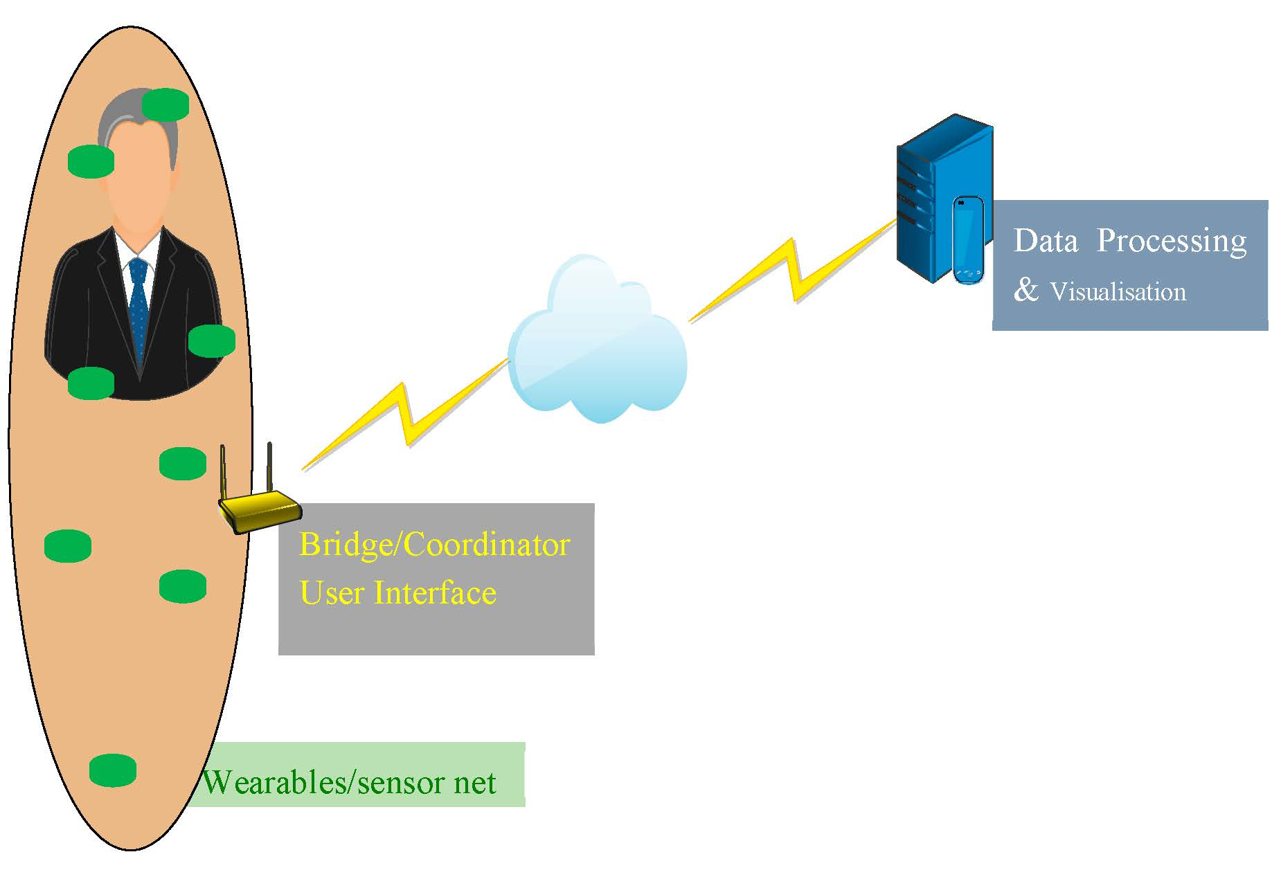
In particular, we look into the use of sensing systems capable of performing measurements of vital physiological parameters—such as electrocardiogram (ECG), blood pressure, spirometry, body temperature, heart pulse, lactic acid, pH just to name a few—and communicating them to a cloud-based processing environment where an intelligent decision-making system processes the collected data with the unique genetic profile of the monitored person in order to determine their actual health and physical condition, follows up progress over time and identifies potentially critical situations. The objective of such a system is not only to monitor individuals’ physical and health condition, but also to generate personalised and updated feedback. By doing so, this converts the current one-size-fits-all health or care guidelines into actions that are tailored to the actual conditions of the monitored individual at a given time.
The concept of prevention now prevails over disease management and treatment plans. As patient-centric processes emerge, the individual undertakes an active role in monitoring their health status, whereas e-wellness evolves to address the rising expectations of the modern consumer, who is better informed, more demanding and broadly empowered. The empowered, worried-well consumers require quality health services on the spot. The drivers are now connectivity, real-time delivery and personalization.
But it is not all bright and easy. For example, pHealth interoperability brings a new challenge to healthcare information systems. All this data requires new models of processing and visualization. By this perspective, interoperability should be seamless, incorporating diverse networked devices and sensors of different vendors. The scale of this challenge is of unprecedented volume, which means that the market adaption needed is not yet in place and has to be delivered accordingly. The aim is to deliver systems that will “plug and play” according to the specifications, following the example of the IT and mobile-technology industries.
The most prominent labeling initiative in pHealth is the Continua Health Alliance, a group of technology, medical device and health and fitness industry players committed to empowering consumers and patients worldwide to take an active role in their own care through the use of technology. Their interoperability profiles are based on the IEEE 11073 family of standards. The standards for the IEEE 11073 PHDs (personal health devices) define the structure of the protocol and functions between the individual medical devices and getaways that are known as managers [10]. The ISO/IEEE 11073-20601 optimized exchange protocol is located in the upper communication protocol layer and consists of the application-layer service and data-exchange protocol. Application-layer service provides a protocol for reliable data transfer and connection management. In other words, ISO/IEEE 11073 PHD defines the Open Systems Interconnection (OSI) protocol stack from layers 5 to 7 and is independent of lower-level protocols. This implies that IEEE 802.15.4 can be used to support the OSI protocol stacks below layer 5 for ISO/IEEE 11073 PHD. The messaging between these stacks has already been studied [11]. In the following section we discuss the implications of the above that have led to the development of the protocol proposed in this paper.
3. Application Framework
Many different protocols have been proposed in the literature for the lower stacks of sensor networks; these are widely known as WSN protocols [12]. To simplify the discussion, consider a sensor network deployed, for example, for monitoring the quality of a plantation or the spread rate of a disease. In such cases, using typical generic network performance metrics to optimize the network formation could result in non-optimal designs. Such metrics, for example throughput or packet delay, do not offer suitable key performance indicators for applications relevant to signal detection and/or parameter estimation per se. Performance should be measured by metrics that are application-related. These can, for example, be loss-detection rate, quality of signal, efficacy and network lifetime. The results will not only then be much more reliable, but also very useful for planning and maintenance.
Application-based protocol design for wireless ad hoc sensor networks is a promising and largely unexplored research area. The new protocol presented here contributes towards it, especially in health-related application environments. Our opinion is that there exist many critical applications for which the strategies developed for conventional wireless sensor networks can be improved in an application-specific context, such as health and wellness.
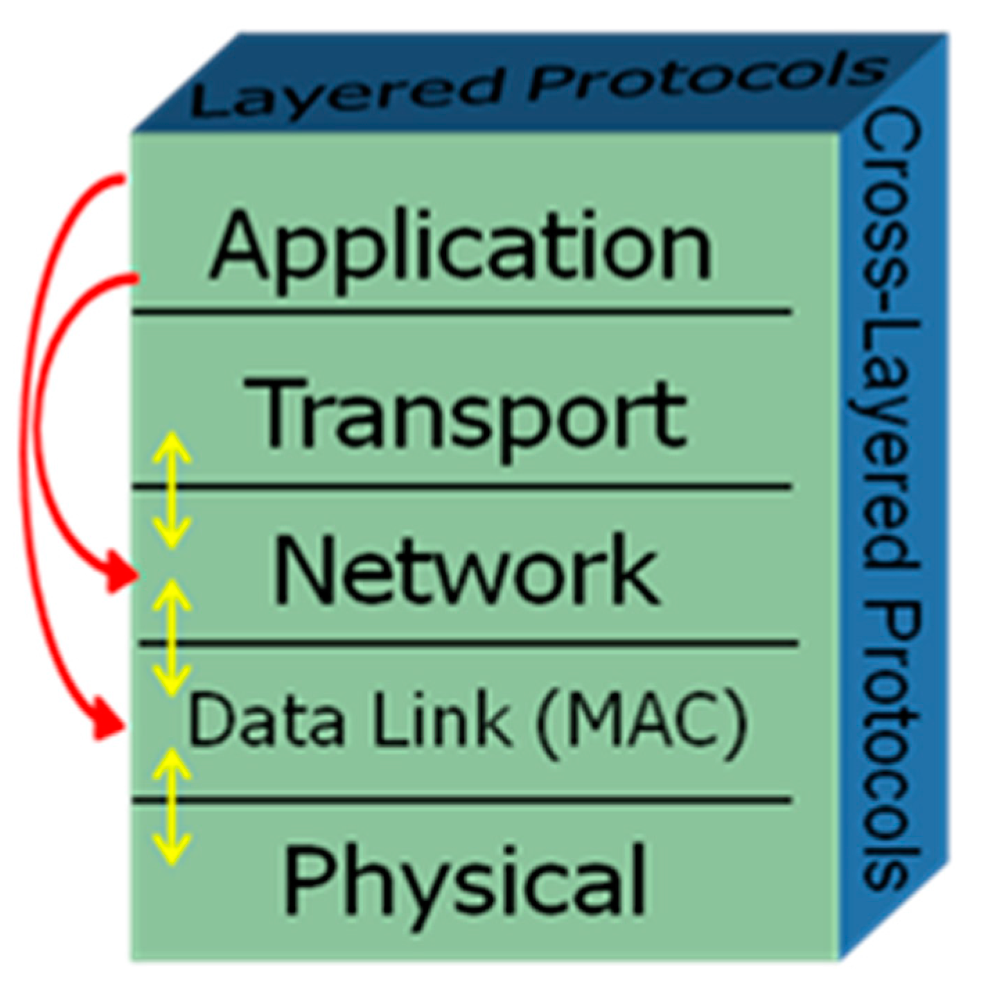
If an application-specific feature is put into perspective, the way protocols are designed could change by shifting the design from the user-centric view to what is known as a data-centric viewpoint. Illustrated in Figure 1 is a schematic representation of layers which shows how cross-layer application-oriented design enters into the proposed protocol picture. Yellow arrows refer to the protocols discussed above; red ones to our approach that led to devising the proposed protocol.
The problem of bridging IEEE 802.15.4 and 802.11 networks has been already studied for healthcare applications [13]. However, in that case the two networks are assumed static unrelated networks and the issue of bridging is examined. In our case, however, the 802.11 network nodes move arbitrarily and when arriving in proximity to the WSN they act as 802.15.4 sinks. This formation, as analytically explained in the next section, represents a realistic scenario for building a monitoring sensor network in the vicinity of a networked electronic community. We will examine how we can solve this network cooperation problem by relying on cross-layer principles.
Our problem definition framework identifies two separate entities. Wireless sensor networks collect data-monitoring QoL parameters such as, for example, environmental factors (water, soil, air), vital signs, health-related human receptors and behavioral patterns. This is referred to as Cloud A. The sensor networks collect various critical data and send them to gateways (sinks is a term widely found in WSN literature as well). Usually, in the literature the sinks are considered part of the WSN. Our case scenario examines a different setting in which the sinks form a different entity, Cloud B. Cloud B acts as a store and forward facility for the acquired data. It forwards data to a gateway to the outer world (Cloud C). In addition to the data collected by the wireless sensor networks, Cloud B may support the collection of other useful information like demographic data, healthcare information, agricultural information, etc. that could be manually or semi-automatically entered. In our framework, networked communities that pre-exist for some other reason or are formed for this particular case implement Cloud B. Examples of such network communities may be found in different scenarios. This could be, for example, smart city implementations, ambulances with wireless access functionality, or smart car networks. Each of the nodes in Cloud B is in general considered a mobile one; by contrast, Cloud A motes are accepted as static (sensor) nodes. Therefore, a node of Cloud B may enter the vicinity of different Cloud A formations at different times. This is also an indication that the dynamic clustering based on the presence proposed here serves our application scenario optimally. There are several possibilities for Cloud B formations. These include ad hoc smart devices, wi-fi networks, or near-field protocols (e.g., Bluetooth, Near Field Communication (NFC)). Finally, another option would be tagging networks based on radio-frequency identification (RFID) and spinners [14]. The Cloud B formation is agnostic to our protocol as long as it equips Cloud B to be able to:
- Collect data from Cloud A implementations (i.e., Cloud B nodes should be able to act as Cloud A motes in parallel);
- Store collected data and (optionally) additional data collected directly in Cloud B;
- (Optionally) process the data;
- Communicate data to the outer world.
For the purposes of our work here, we assume that Cloud B is an ad hoc wireless mesh network (WMN) based on the IEEE 802.11s network and Cloud A is an IEEE 802.15.4 WSN serving an IEEE 11073 PHD implementation stack. The generality of these assumptions is enough to ensure wide applicability of the proposed solution [15].
Among the various algorithms for WSN protocols proposed, of particular interest to us is the low-energy adaptive clustering hierarchy (LEACH), which is a routing algorithm designed for a unidirectional flow of data, with the main objective to extend the network lifetime by reducing the energy consumption by each mote, exploiting the use of data aggregation to reduce the number of communication messages [16]. LEACH is a cluster-based network-routing algorithm. Each cluster in LEACH is managed by a selected cluster head, that:
- Periodically collects data from the members of the cluster and aggregates it;
- Transmits the data directly to the base station over a single hop;
- Creates a time-division multiple access (TDMA) based schedule whereby each mote is assigned a time slot that it can use for transmission;
- Selects a code-division multiple access (CDMA) code, so as to reduce intercluster interference.
Simulation results show that LEACH achieves significant energy savings. The algorithm presented here is a variant of the LEACH protocol adapted to the needs of wearable-enabled pHealth scenarios.
4. Network Formation Algorithm
4.1. Design
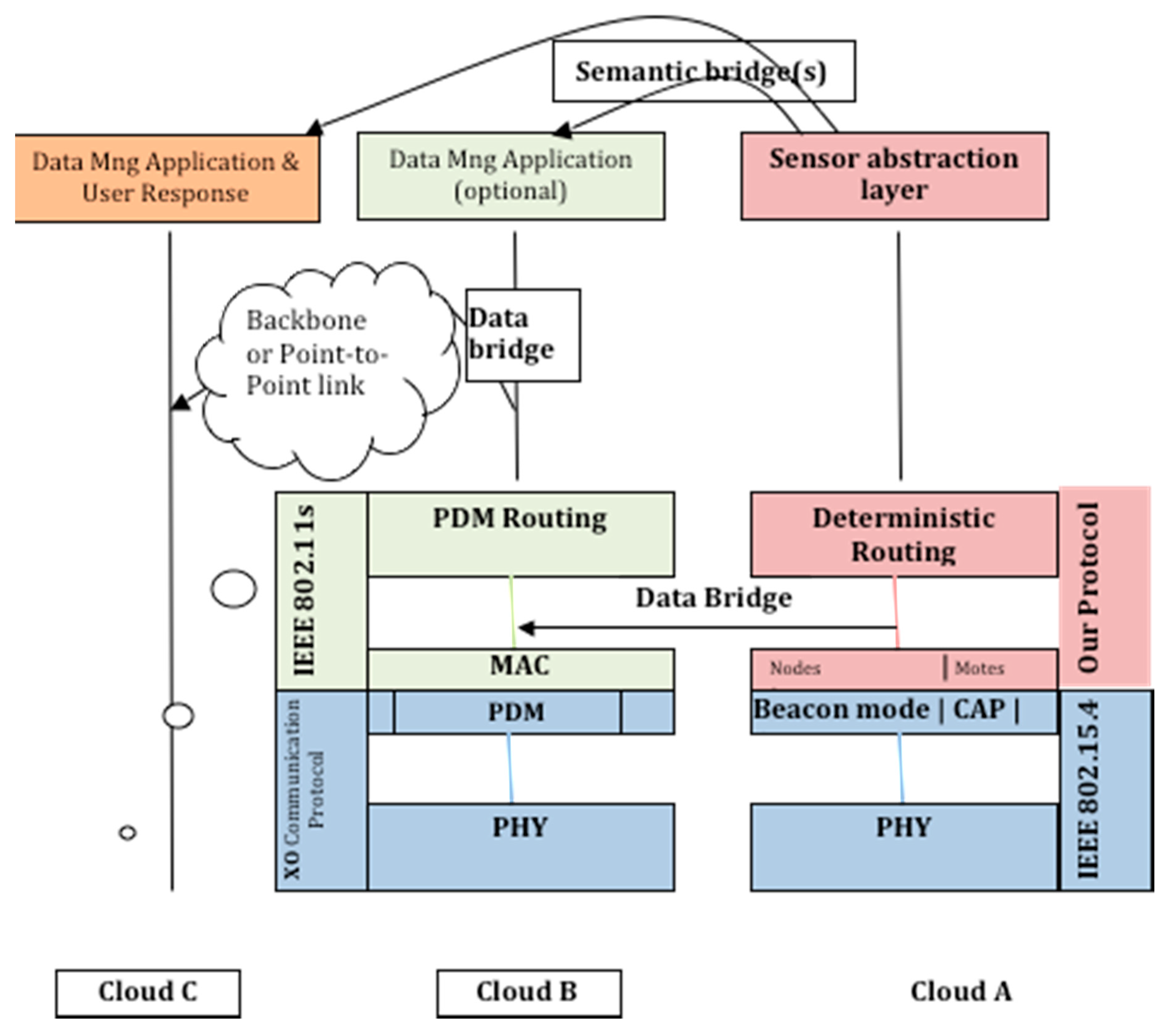
We describe a sensor network formation algorithm to exploit the application environment in the framework presented previously. Figure 2 shows the basic protocol architecture in terms of its relation to the cooperation protocols in the three interconnecting Clouds A–C. It displays the cross-layer nature of the Cloud A–Cloud B cooperation scheme. Our protocol introduces presence advertisement as a new way of routing at the Network layer (NET layer). It solves the problem at the Medium Access layer (MAC layer) and the link layer and exploits a path discovery protocol we developed that solves the problem at the link/physical (PHY) layers. This way our protocol advances the concept of the WMN, which is basically a collection of fixed nodes, most of the time consisting of regular access points running adapted software, to a routing optimized network of moving and non-continuously present access points (Cloud B nodes). Its main goal is to provide an inexpensive and easily deployable wireless backhaul.
The cooperation of the two networks results in a dynamic clustering of Cloud A as coordinated by the Cloud B node mobility and mesh formations. The network is formed in four phases as summarized in Table 1.
4.2. Formation
4.2.1. Phase 1: Assumptions and IEEE 802.15.4 Parameters
Motes self-organize themselves according to IEEE 802.15.4; self-organization implies that all motes have the status of an FFD (full-function device) [17]. In our application scenario, an ad hoc clustered-tree multihop topology is supported (Figure 3). Cluster heads and network coordination is assumed by Cloud B nodes. This results in higher energy efficiency and a longer lifetime for Cloud A. A beacon mode with a superframe is used.
Parent and child roles are interchangeable. A child to mote X at some instance may become a parent to mote X. This is the result of changes in network topology as nodes of Cloud B enter, leave or move in respect to Cloud A. The phase 1 route formation of Cloud A (a IEEE 802.15.4 cluster—tree) is stored as the default status in every mote. Information regarding children and the parent is stored on the motes to be utilized by upper layers.
4.2.2. Phases 2–4: Operation Phases
We consider three different operation cases. In all of them Phase 1 is considered completed. In any of the Phases 2–4 one or more nodes appear in the vicinity of Cloud A and start their dual operation as motes, as explained before. In such cases at least one node is assumed operating as a mote as well. For the Cloud A motes, different possibilities of operation exist depending on their distance (physical or logical) from the node(s). These are:
- Motes that directly communicate with a node; we call them Hop 0 motes;
- Motes that have no children, i.e., they do not act as receivers/repeaters of information from other motes; we call them childless motes;
- Motes that both receive and transmitting communication links with other motes; we call them parent/child motes.
Look-up tables exist in the network motes; each table acts as a ledger that contains information on the available Cloud B nodes in the formation and they are updated through a flooding mechanism as nodes advertise their presence or disappear. All nodes have an entry in the look-up table of each mote, except for the Hop 0 whenever it exists.
4.3. Cross-Layer Design
4.3.1. Physical Layer
We assume a set of motes forming a IEEE 802.15.4 tree topology wireless ad hoc sensor network (Cloud A) [18]. Additional to the motes we assume a set of nodes forming a mesh network (Cloud B). Considerations at the PHY layer include band selection (e.g., 2.4 GHz is a common band, so cost is kept down, but interference must be studied), antenna design and system on chip (SoC) specifications. These issues are not addressed in this paper. A relevant discussion may be found in [19].
4.3.2. MAC Layer: Presence Information
Each node advertises itself as a sink to Cloud A. This is achieved by having each node broadcast a presence entry. All motes that receive the entry and do not have a one-hop relation to another node set the advertising node as their sink. Motes that already have a one-hop relation with a node ignore the invitation. In this case, the network topology does not change in the child tree branches of these motes.
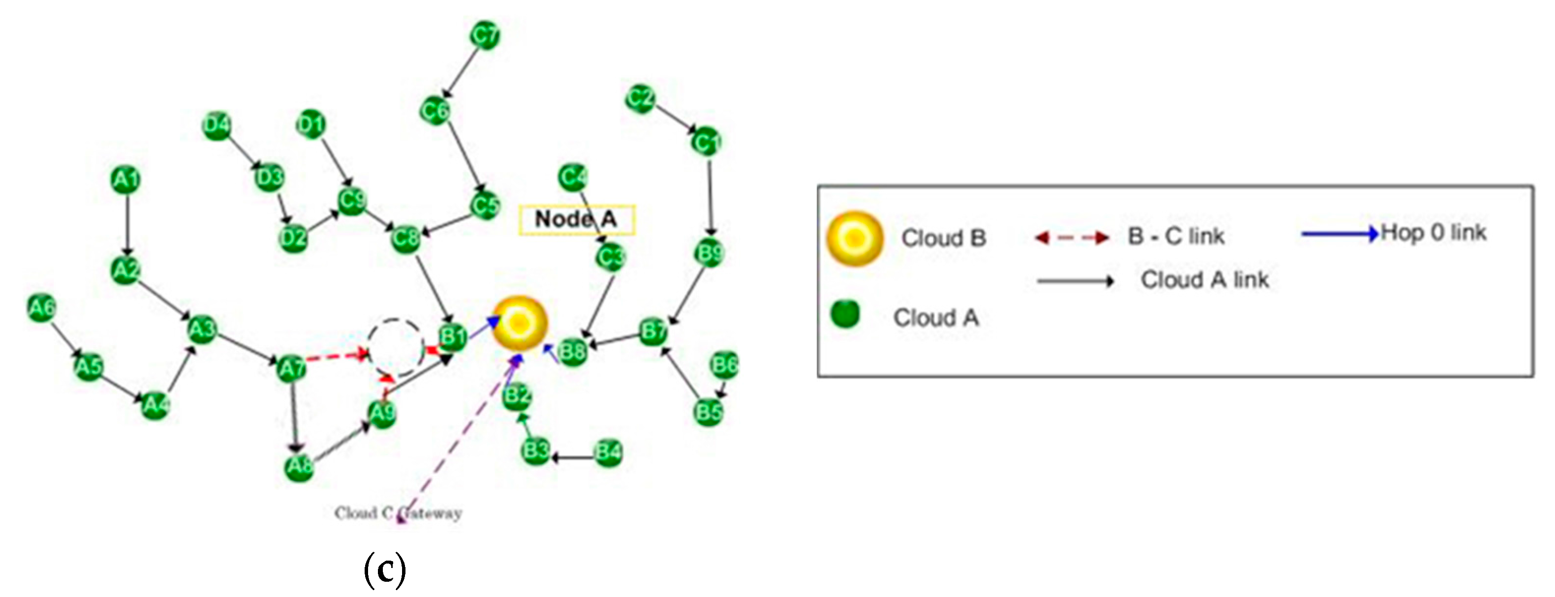
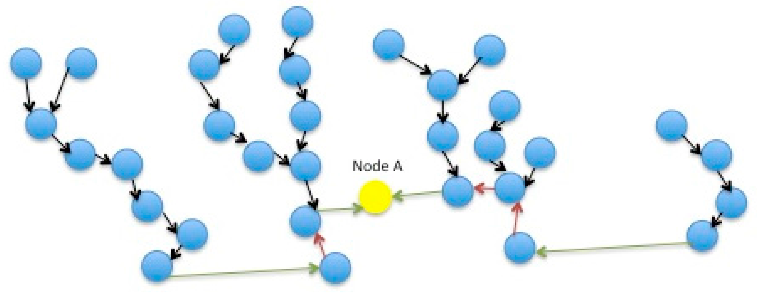
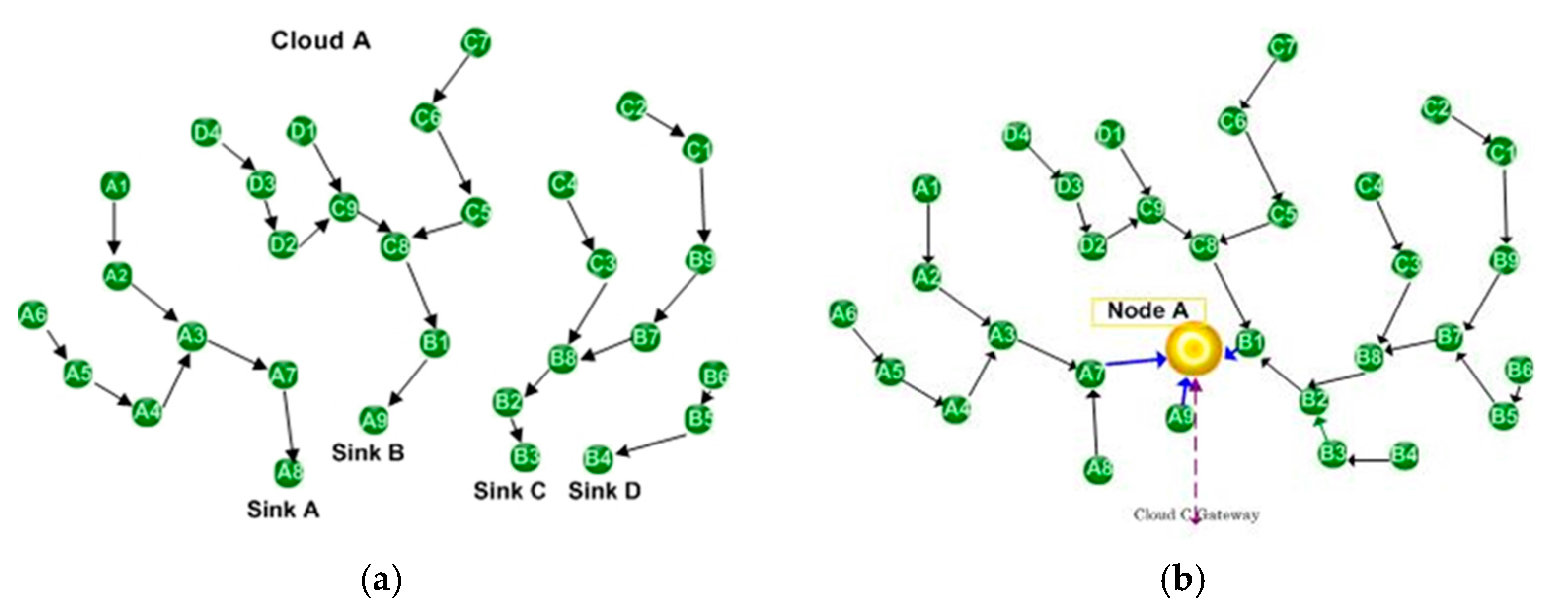
The motes that decide to accept the node as a cluster head, become hop 0 motes for this cluster. The first node that arrives in the proximity of Cloud A assumes the role of the coordinator of Cloud A. This is shown in Figure 4. The arrival of a first node results in reversal of the direction of information flow in some of the mote relays (red arrows) and the creation of new links both between motes and between a mote and the node (green arrows). All subsequent nodes will form independent clusters. The coordinator could act as a gateway to the outer world as well; other nodes may also act as gateways, that may act as cluster heads or not. The coordinator role may be transferred between nodes.
4.3.3. MAC Layer: Clustering
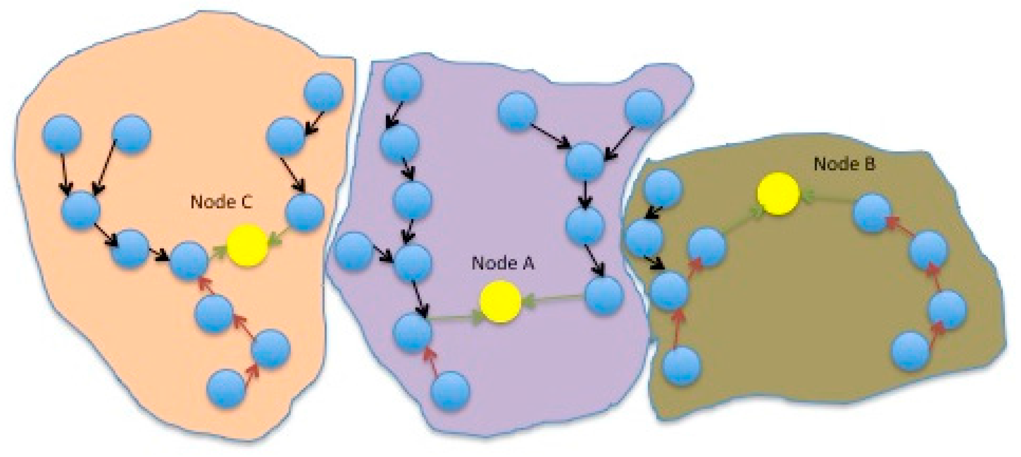
Nodes broadcast presence entries as they move. When a mote establishes a direct connection with a node, it informs its neighbors; for this purpose it transmits a presence entry itself. In case any of these motes has a 2 or higher hop distance, they transverse their traffic to the mote in question. It may be that the parent of this mote will now become its child. An example is shown in Figure 5, where the presence of three nodes results in the formation of three clusters, different than the original four of the typical IEEE 802.15.4 (Figure 3). In general, whenever a node sends a presence entry, the following changes in the routing path may occur (in all cases motes disassociate from their past parent node and associate with the new one):
- Cloud A links broke for the motes that connect directly to the node;
- Cloud A links reverse for the parent motes that decide to use a new route to case A motes;
- New cloud A links are formed; for each link formed, one link disappears.
Motes propagate backwards the new routing status. When any of the above changes occurs, a new clustered-tree network topology is formed.
4.3.4. Inter-Cluster Organization
A node before advertising its presence must consult the already participating nodes. For this reason it broadcasts over the WMN (Cloud B) a cluster availability request. All nodes will propagate the request to the whole network. When the request reaches the coordinator node, it will reply by denoting the PHY channels that are used by the participating nodes and their IDs. The coordinator node will additionally denote its role. When this information is available, the node will choose one of the remaining channels and will send its presence entry. If it does not receive an association request from at least one mote within some time, then either there are no interested motes in its range or it is using an occupied channel. The presence is advertised repeatedly. Association requests may be received at any rotation cycle. When this is the case, the request is acknowledged. This means that a new cluster has emerged and this information is broadcasted to the other nodes in Cloud B. The mote that transmitted the association request is by default the new cluster Cloud A coordinator, which maintains also the responsibility of keeping the information on the cluster. It should be noted again that clustering, meaning communication between clusters, formation and release of clusters is performed at the Cloud B level, thus making the protocol agnostic of the Cloud B implementation specifics.
4.3.5. Broken Links
Although the IEEE 802.15.4 MAC Disassociation Command may be used, the most usual reason for disassociation of Cloud B nodes is mobility. Therefore, such a command is not very useful (power shutdown could be one case where this Command could be useful; exploitation of the potential accelerometer functionality (in case for example the node is implemented in a smartphone) is another). Our protocol supports the following mechanism for cases where the disassociation command cannot be issued.
A node must inform all connected motes every τ seconds on its status. If a child hop 0 mote does not receive a presence entry from the node at which it is connected for t > 2τ, then it transmits a query beacon to that node. If after 2τ the mote still has not received a presence entry, it concludes that the node is no longer available and tries to connect to other available nodes stored in the look-up table it maintains. If such nodes are not available or if the look-up table is empty, the mote establishes its default Cloud A link and informs its default parent mote.
It then also informs all its child status by definition of the protocol neighbor nodes that had transverse their relate links through it so that they link to another node or return their default status following a similar procedure to the one described above for hop 0 motes.
Cloud A broken links due to, for example, power exhaustion hardware failure or mote movement, are treated as in IEEE 802.15.4 cluster-tree topologies [20].
5. Traffic and Power Overhead
The traffic experienced by a mote due to presence information received by its neighbors depends on the local density and the total size of both the Cloud A network (M) and the Cloud B network (N). A node will receive as many presence entry packets as it has neighbors other than its parent (presence entry packets from parents are ignored; see below) and as many nodes exist. As a result, we might want to adapt the rate at which neighbors are sending presence entry packets and/or the number of motes that each node covers. We discuss below how these two parameters affect network performance in terms of additional traffic and power requirements.
Τraffic experienced by the network due to presence entry packets broadcasted depends on the size of Cloud A and the number and movement rates of Cloud B nodes. The overhead traffic is generated as a node enters, leaves or moves around the Cloud A area. As a result, the traffic overhead will grow as O (N.M), where N = [nodes in the coverage area of Cloud A] and M = [number of motes of Cloud A].
Note that the nodes-oriented traffic is a very structured traffic. For one thing, the cluster head can include the presence entry information in the beacon payload. That would mean that traffic does not increase from node oriented presence entry information. Mote-oriented presence entry information, however, does generate extra traffic. As this is highly concentrated traffic the hop 0 motes presence entry packets are broadcast using the superframe Guaranteed time slot (GTS) slots. We can assume that motes of higher hop values transmit backwards node presence information through the Carrier-sense multiple access with collision avoidance (CSMA-CA) competed slots. Thus, the cluster lead allocates GTS slots to all hop 0 motes for them to transmit its presence entry. Whenever a node moves, every mote that changes status and associates with its cluster will broadcast a presence entry. Motes on its child branches will ignore it, as well as all other hop 0 motes, but the rest of the nodes will listen to it, including its parent and if the distance to Cloud B lowers, they will redirect their traffic through it. In more advanced implementations of the algorithm the motes may decide on additional criteria to the distance, e.g., criteria that take into account storage, processing or power constraints. All motes deciding to redirect traffic will also retransmit the presence entry of the node they associated with.
Figure 6 shows a spatiotemporal example of network formation in beacon and packets graphical representation. The horizontal axis represents space, whereas the vertical one time. t0 denotes the time that Node A after moving in transmits its presence entry for the first time in its new position. Range (t1–t0) and (t4–t2) is the superframe active portion; (t2–t1) and (t5–t4) is the superframe inactive portion; (t2–t0) = (t5–t2) is the beacon interval (BI). As the IEEE 802.15.4 defines the active portion can be divided to the Contention Access Period (IEEE 802.15.4) (CAP) period (CSMA-CA competition slots) and the Contention Free Period (IEEE 802.15.4) (CFP) period (GTS assigned slots). In the figure CAP is (t6–t5) and (t3–t2), whereas the CFP is (t4–t3) and (>t6). In terms of colours, green denotes beacons, purple denotes CAP packets, and blue denotes CFP packets. Therefore, the overhead traffic grows as O(M*N) in total and as O(M) per cluster.t
Why O(M)? Think of the two extremes: on the one end all motes become hop 0 motes; then they will broadcast M presence entry packets which will be ignored; on the other end only one tree exists, so only one presence entry packet will be distributed; one can show that in an arbitrary arrangement the number of packets transmitted is between 1 and M.
Why O(N)? The worst-case scenario denotes that nodes are at constant movement so every beacon transmitted generates network topology changes. This is an extreme scenario and can be proactively controlled by prohibiting nodes from transmitting beacons while in fast-transit modes.
While a node does not move, it still transmits a static presence entry, which however is not broadcasted backwards by the hop 0 motes. Therefore, in this case the overhead traffic is negligible. As a result, only the continuous movement scenario is worth exploring further.
Making the assumption that cluster heads transmit beacons at the prescribed rate of IEEE 802.15.4, the overhead traffic can be adapted by configuring motes to listen to other nodes’ beacons at prescribed time intervals. It is obvious that each node transmits its presence entry information every BI (as defined in IEEE802.15.4). One possible scenario will be for a mote to listen for other nodes every 1 + λ*4 beacons, where λ is the number of nodes featuring at its look-up table at a given instance. Thus, the fewer alternative routes a mote has, the more intensively it looks for them.
These channel switches for sensing neighbouring nodes consume extra power of a mote as well. Longer idle times may be chosen for hop 0 motes, whereas longer distance motes would check more regularly, the reasoning being that longer distance motes increase exponentially the consumed power of the network. Note that a hop X note requires X retransmissions which, on average, would mean O(Px) energy consumption, where P is the average hop 0 transmission energy. A good rule of thumb is number of changes (nc) = [A − (h/s)A], where h = distance (number of hops), s = cluster depth (s = max (h)) and A = 10v s = α10v, 0 < a < 10, i.e., nc = [A − h/a]. Thus, a hop 0 mote in a cluster of distance 40 will check other nodes’ presence every 10BI whereas a hop 10 node every 7BI (more frequently).
The example in Figure 7 shows the neighbourhood tables of the Cloud A in Figure 8a at three different instances: default value, at time T1 when Node A enters the Cloud A (Figure 8b) and at T2 when Node A moves into a new position within Cloud A (Figure 8c). For space preservation, only motes that change their status are presented.
6. Simulation Results
We define presence as a new way of routing. Presence information identifies a node or a mote in terms of its participation in a route (i.e., tree) in a sensor network. Our solution uses application-layer information and then focuses on exploiting the collaboration of the two networks, achieving lower network-formation traffic:
- Only cloud B nodes are mobile;
- Only cloud A motes transmit data (sensor information); nodes only retransmit data;
- Broadcasting is not required.
The network formation protocol described here resembles design and performance issues of cluster interconnection for beacon-enabled 802.15.4 clusters. Our approach, in which the cluster coordinator is used to bridge clusters, is known to be superior in terms of traffic. Note also, that in a simplified case, where enough nodes exist to cover the network area of Cloud A fully, i.e., so as all motes become hop 0 motes, then our protocol operates as a static LEACH [16] network, which is known to have superior energy savings compared to other existing WSN MAC approaches.
We simulated using Opnet a formation of 50 sensors (motes) randomly covering an area of 20 × 100 m, through which nodes go moving at a steady speed of 2 m/s along random trajectories. We assumed the following parameters: packet length: 30 bytes, interface queue (IFQ) length: 65 packets, power of transmitter (all motes) 0.66 W, power of receiver (all motes): 0.395 W, radio range (all nodes): 40 m. The results for one, two and three nodes simultaneously traversing through the examined area are presented in Figure 7, where one can note that on average three nodes can minimize the required hops.
The simulation scenario reflects the real situation of Cloud B nodes entering the Cloud A space, moving along a random trajectory across Cloud A, and finally leaving. Three cases are examined with one, two and three nodes traversing simultaneously, respectively. The algorithm maximizes at a given instance the number of hop 0 motes, minimizing thus energy consumption and memory requirements. As seen in Figure 7, as the nodes move across Cloud A the number of hop 0 motes increases, thus decreasing the average path-to-sink distance. The routing via presence advertising is proved to work optimally as a result of the cross-layer nature of the protocol. As is seen in Figure 7b, for the case of three nodes there are instances where all motes are hop 0.
The main performance metric of interest is the duration of network operation until a sensor node “dies” for the first time. We observe that our protocol performs significantly better than existing solutions. The lifetime achieved by it in Figure 8a is 23.5% higher than that of LEACH for 20 motes, while this rises to 108.6% for 100 motes. Standard deviation shows no significant statistical error.
7. Discussion
Various routing algorithms have been proposed for WSNs [3]. Among them the minimum energy routing and the minimum hop routing suffer from different inefficiencies, the main ones being that they deplete energy in certain frequently used routes and create congestion. Our assumption is that in our application scenarios all motes are equally important and share the same energy and storage characteristics.
Homogeneous approaches are closer to our needs. These mostly work by applying a probabilistic choice of the route to use (or the mote to send the next packet) over a set of routes or motes calculated or determined as of least power consumption or minimizing a metric such as residual battery life. All such approaches consider the network as a general purpose network. WSNs, however, usually do not fit into that rule; they tend to be application-dependent, (almost) unidirectional, and of predictable rate and thus data flow. In other words, WSNs tend to be (almost) deterministic, as opposed to general purpose wireless networks. This is particularly true for medical WSN application, where each measurement is usually equally critically important whereas, on the other hand, information regarding data type and flow is predictable to a high degree.
Application-based protocol design has been studied mostly for the case of cooperation schemes where measurements are inter-correlated and thus redundancy exists [20]. Our scenarios focus on independent measurements. The uncertainty in our case is “controlled” by the moving nodes of Cloud B. This means that at every transmission instance each mote of Cloud A has to find the shortest path to the Cloud B, i.e., to the “closest” node of it. We defined here for the first time for health sensor networks the use of presence as a new way of routing. This approach has already been demonstrated successfully in a mobile peer-to-peer network setting [21]. Our solution focuses on exploiting the collaboration of the two networks, achieving lower network-formation traffic. As already mentioned, the routing algorithm of our protocol resembles that of low-energy adaptive clustering hierarchy (LEACH). LEACH adopts a hierarchical approach to organize the network into a set of clusters. Each cluster is managed by a selected cluster head. Simulation results show that LEACH achieves significant energy savings. However, this is only achieved if certain assumptions are valid; these assumptions may evolve to become shortcomings. For example, the assumption that all nodes can reach the base station in one hop may not be realistic, and the length of the steady-state period which is critical to achieving the energy savings may not be suitable for particular applications. Our protocol overcomes these shortcomings by introducing application-layer information in the decisions. For example, the rotation of cluster heads appearing in LEACH in order not to exhaust specific motes is irrelevant to us, as the Cloud B nodes are exploited. Furthermore, the steady-state period is irrelevant to the protocol and is only dependent on the application features. Finally, the cluster-tree topology adopted here is a direct expansion of the LEACH protocol. Note, that in a simplified case, where enough nodes exist to cover the network area of Cloud A fully, i.e., so all motes become hop 0 motes, then our protocol operates as a static LEACH network, which is known to have superior energy savings compared to other existing WSN MAC approaches [15].
The protocol we propose here describes a formation mechanism in which performance and design issues emerge that one can relate to 802.15.4 clusters which operate in the beacon mode. The literature presents evidence that by following our approach, where the cluster coordinator, in our case a Cloud B node, has the responsibility to act as a bridge to neighbouring clusters, traffic and efficiency are optimal [22]. The price to pay is that the cluster coordinators are prone to security attacks and represent a single point of failure. However, our proposed algorithm overcomes these shortcomings through the use of Cloud B cluster coordinators instead of the typically used motes. This approach is novel to the best of our knowledge.
8. Further Work and Conclusions
As we move towards holistically interconnected living environments a lot of issues will emerge, including interoperability to existing infrastructures, legal and ethical considerations, as well as cost and implementation questions. When it comes to health-sensor networks in particular, the issues of cost and effort become extremely significant and both have to be substantially justified. Any implementation can only be justified if a quantified substantial need can be presented. There are different parameters that can be used to quantify the need. Important examples of these include reduction in human and infrastructure resources, improvement in decision making accuracy, and implementation of a novel service that is not possible to realise with other technological means.
Nonetheless, wearable-enabled monitoring installations turn out to have a well-suited potential for many application areas. Although back-end communication infrastructures are needed to interface wireless-sensor networks with the Internet or a local area network, they can also function in the absence of any communication infrastructure. This makes them particularly attractive for dense traffic environments where the presence of stable communication infrastructures at all times may not be feasible. On the other side of the coin, because of their self-organising characteristics and robustness, wireless-sensor networks can be deployed in less benign environments and inaccessible places as well as in places where employing humans is difficult or costly.
Today, a wireless-sensor network is almost the only ICT means we have that can operate independent of any external communication infrastructure or/and electricity network. Our initial results presented here show promising potential in this area. In the near future, we are planning a pilot roll-out of the system in a demanding IoT-5G use case to test it in an actual setting.
Conflicts of Interest
The authors declare no conflict of interest.
References
- Angelidis, P. Personalised physical exercise regime for chronic patients through a wearable ICT platform. Int. J. Electron. Healthc. 2010, 5, 355–370. [Google Scholar] [CrossRef] [PubMed]
- Labrique, A.; Vasudevan, L.; Chang, L.W.; Mehl, G. Hope for mHealth: More “y” or “o” on the horizon? Int. J. Med. Informat. 2013, 82, 467–469. [Google Scholar] [CrossRef] [PubMed]
- Akyildiz, I.F.; Su, W.; Sankarasubramaniam, Y.; Cayirci, E. A survey on sensor networks. IEEE Commun. Mag. 2002, 40, 102–114. [Google Scholar] [CrossRef]
- Yu, H.; He, X.; Ding, W.; Hu, Y.; Yang, D.; Lu, S.; Wu, C.; Zou, H.; Liu, R.; Lu, C.; Wang, Z.L. A self-powered dynamic displacement monitoring system based on triboelectric accelerometer. Adv. Energy Mater. 2017, 7, 1700565. [Google Scholar] [CrossRef]
- He, X.; Zi, Y.; Yu, H.; Zhang, S.L.; Wang, J.; Ding, W.; Zou, H.; Zhang, W.; Lu, C.; Wan, Z.L. An ultrathin paper-based self-powered system for portable electronics and wireless human-machine interaction. Nano Energy 2017, 39, 328–336. [Google Scholar] [CrossRef]
- Dohler, M.; Aghvami, A.H. Distributed antennas: The concept of virtual antenna arrays. In Cooperation in Wireless Networks: Principles and Applications; Fitzek, F.H.P., Katz, M.D., Eds.; Springer: Dordrecht, The Netherlands, 2006. [Google Scholar]
- Angelidis, P. Uptake of pHealth: Has the time come to become a commodity? In Mobile Lightweight Wireless Systems; Springer: Berlin/Heidelberg, Germany, 2007. [Google Scholar]
- Yang, G.-Z. Body Sensor Networks, 2nd ed.; Springer: Berlin/Heidelberg, Germany, 2014; 580p, ISBN 9781447163732. [Google Scholar]
- Abidi, S.S.; Goh, A. A personalised healthcare information delivery system: Pushing customised healthcare information over the WWW. Stud. Health Technol. Informat. 2000, 77, 663–667. [Google Scholar]
- Ji, Z.; Zhang, X.; Ganchev, I.; O’Droma, M. A personalized middleware for ubiquitous mHealth services. In Proceedings of the 2012 IEEE 14th International Conference on e-Health Networking Applications and Services (Healthcom), Beijing, China, 10–13 October 2012; pp. 474–476. [Google Scholar]
- Oryema, B.; Kim, H.S.; Li, W.; Park, J.T. Design and implementation of an interoperable messaging system for IoT healthcare services. In Proceedings of the 2017 14th IEEE Annual Consumer Communications & Networking Conference (CCNC), Las Vegas, NV, USA, 8–11 January 2017; pp. 45–52. [Google Scholar]
- Bachir, A.; Dohler, M.; Watteyne, T.; Leung, K.K. MAC essentials for wireless sensor networks. IEEE Commun. Surv. Tutor. 2010, 12, 222–248. [Google Scholar] [CrossRef]
- Misic, J.; Misic, V.B. Bridging between IEEE 802.15.4 and IEEE 802.11b networks for multiparameter healthcare sensing. IEEE J. Sel. Areas Commun. 2009, 27, 435–437. [Google Scholar] [CrossRef]
- Lifton, J.; Laibowitz, M.; Harry, D.; Gong, N.W.; Mittal, M.; Paradiso, J.A. Metaphor and manifestation—Cross reality with ubiquitous sensor/actuator networks. IEEE Pervasive Comput. Mag. 2009, 8, 24–33. [Google Scholar] [CrossRef]
- Sohraby, K.; Minoli, D.; Znati, T. Wireless Sensor Networks: Technology, Protocols, and Application; John Wiley & Sons: Hoboken, NJ, USA, 2007. [Google Scholar]
- Heinzelman, W.R.; Chandrakasan, A.; Balakrishnan, H. Energy-Efficient Communication Protocol for Wireless Microsensor Networks. In Proceedings of the 33rd Annual Hawaii International Conference on System Sciences, Maui, HI, USA, 7 January 2000; pp. 1–10. [Google Scholar]
- Xiao, Y.; Pan, Y. Emerging Wireless LANs, Wireless PANs and Wireless MANs; Wiley: Hoboken, NJ, USA, 2008. [Google Scholar]
- IEEE 802.15.4-2006. Wireless LAN MAC and PHY Specifications for LR-WPANs; IEEE: New York, NY, USA, 2006. [Google Scholar]
- Heinzelman, W.R.; Kulik, J.; Balakrishnan, H. Adaptive protocols for information dissemination in wireless sensor networks. In Proceedings of the 5th Annual ACM/IEEE International Conference on Mobile Computing and Networking, Seattle, WA, USA, 15–19 August 1999; pp. 174–185. [Google Scholar]
- Radeke, R.; Marandin, D.; Claudios, F.J.; Todorova, P.; Tomic, S. On reconfiguration in case of node mobility in clustered wireless sensor networks. IEEE Wirel. Commun. 2008, 15, 47–51. [Google Scholar] [CrossRef]
- Ypodimatopoulos, P.P. Cerebro: Forming Parallel Internets and Enabling Ultra-Local Economies. Master’s Thesis, Science in Media Arts and Sciences at the MIT, Boston, MA, USA, 2008. [Google Scholar]
- Cui, S.; Madan, R.; Goldsmith, A.; Lall, S. Cross-layer energy and delay optimization in small-scale sensor networks. IEEE Trans. Wirel. Commun. 2007, 6, 3688–3699. [Google Scholar] [CrossRef]
Figure 1.
Cross-layer design. Yellow arrows refer to existing protocols discussed in the section; red ones to our approach that led to devising the proposed protocol.
Figure 1.
Cross-layer design. Yellow arrows refer to existing protocols discussed in the section; red ones to our approach that led to devising the proposed protocol.

Figure 2.
Protocol architecture. Arrows represent cross layer bridges.

Figure 3.
Phase 1: typical IEEE 802.15.4 clustered peer-to-peer ad hoc formation.
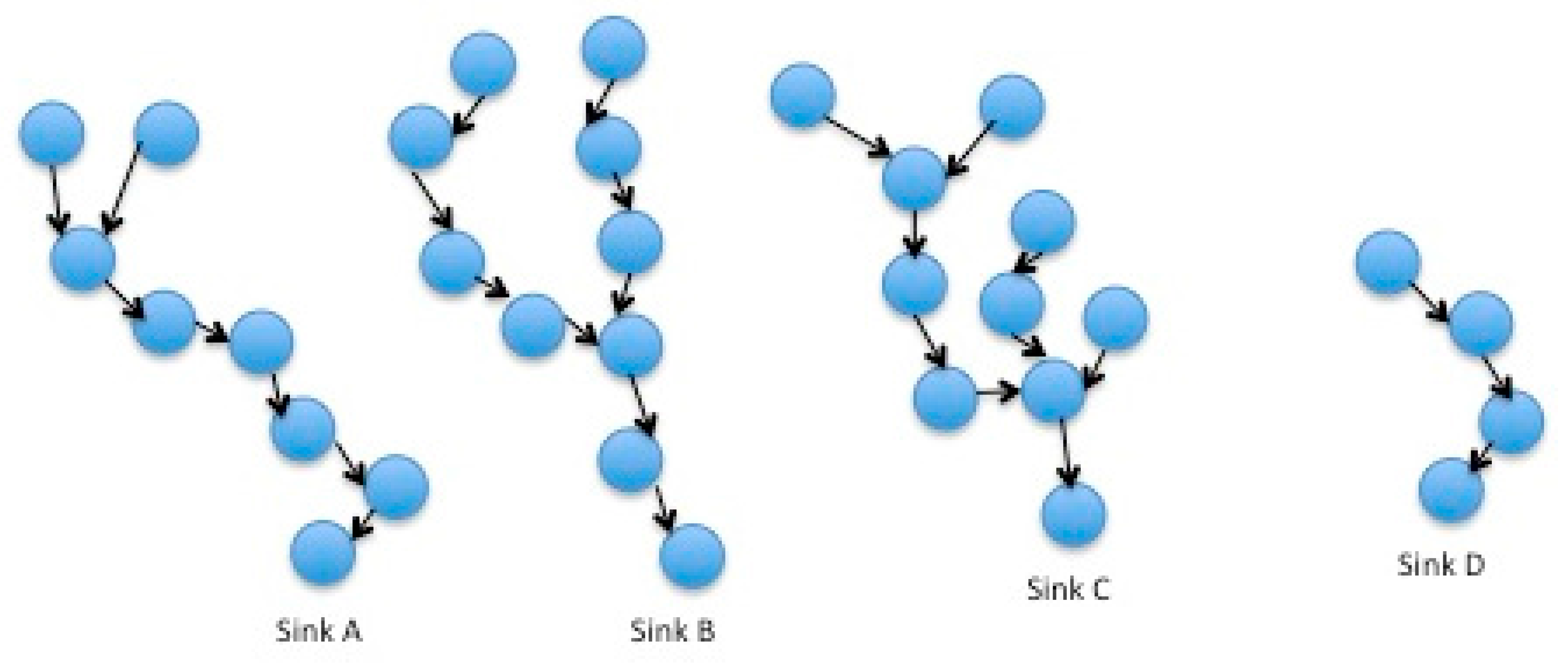
Figure 4.
Phase 2: network in its infancy. Non-affected links (black arrows). Reversal of the direction of information flow (red arrows). Creation of new links both between motes and between a mote and the node (green arrows).
Figure 4.
Phase 2: network in its infancy. Non-affected links (black arrows). Reversal of the direction of information flow (red arrows). Creation of new links both between motes and between a mote and the node (green arrows).

Figure 5.
Phases 3 and 4: structured network and maturity. Non-affected links (black arrows). Reversal of the direction of information flow (red arrows). Creation of new links both between motes and between a mote and the node (green arrows).
Figure 5.
Phases 3 and 4: structured network and maturity. Non-affected links (black arrows). Reversal of the direction of information flow (red arrows). Creation of new links both between motes and between a mote and the node (green arrows).

Figure 6.
Spatiotemporal example of overhead network traffic.

Figure 7.
(a) Number of Hop 0 motes (left), (b) maximum number of hops (right) for nodes moving through the Cloud A area, (c) cases of one (diamonds), two (squares) and three (dots) moving Cloud B nodes.
Figure 7.
(a) Number of Hop 0 motes (left), (b) maximum number of hops (right) for nodes moving through the Cloud A area, (c) cases of one (diamonds), two (squares) and three (dots) moving Cloud B nodes.
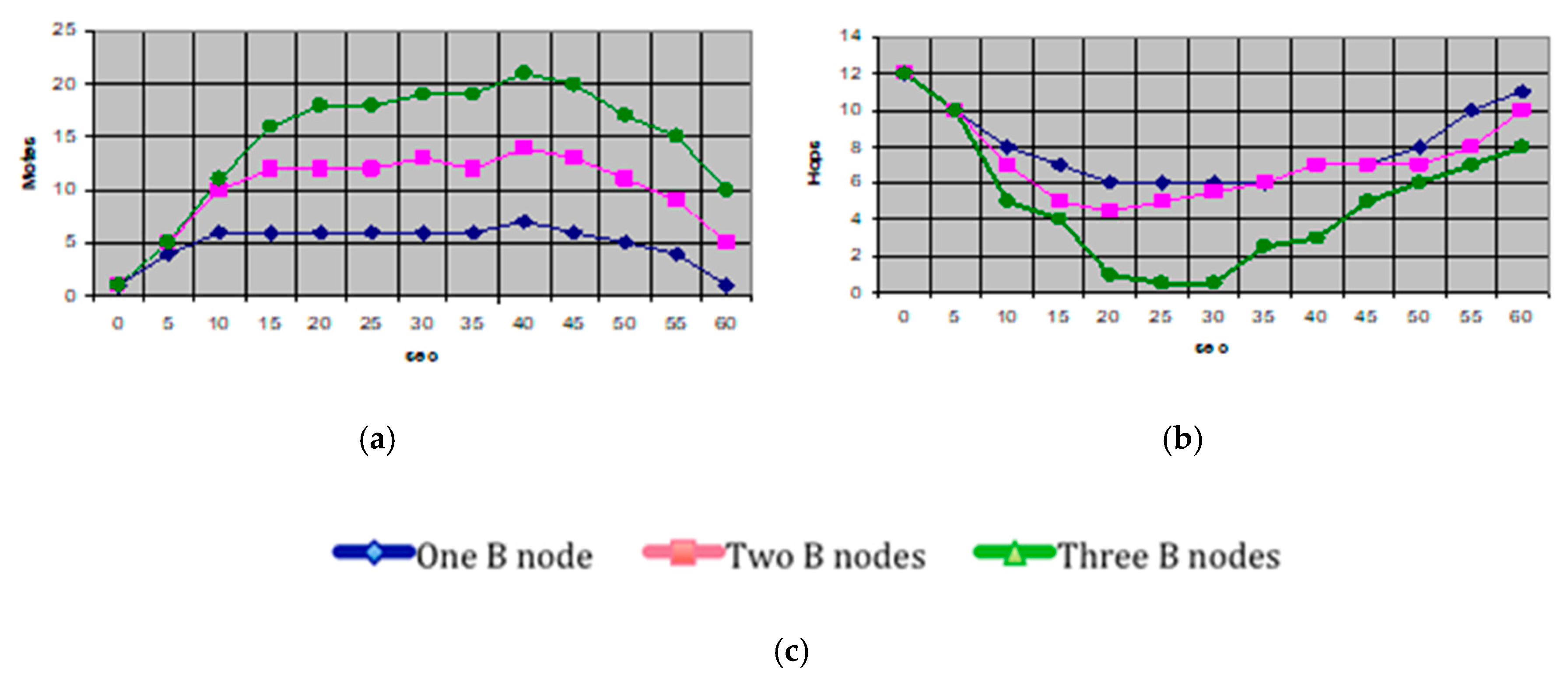
Figure 8.
Network formations for the example of Figure 7. (a) typical IEEE 802.15.4 clustered peer-to-peer ad hoc formation in the absence of a node; (b) network structure as one node appears; (c) network restructuring as the node moves into a new position.
Figure 8.
Network formations for the example of Figure 7. (a) typical IEEE 802.15.4 clustered peer-to-peer ad hoc formation in the absence of a node; (b) network structure as one node appears; (c) network restructuring as the node moves into a new position.


Table 1.
The four different formation phases of the network.
| Phase | Description |
|---|---|
| Phase 1: <kick-off> Figure 1 | Motes self-organized or pre-programmed. Sinks are preselected depending on geography (i.e., likelihood of node appearance), sensing parameters, storage capacity or arbitrarily, in case relevant information does not preexist. |
| Phase 2: <one node phase> Figure 2 | A node in proximity advertises its presence; being the only node it serves also as the network coordinator and the gateway; if no direct link to the outer world exists, information is stored in this node temporarily. |
| Phase 3: <structuring> Figure 3 | As other nodes enter, motes reorganize themselves depending on the identity information advertised by each node; nodes self-organize to decide on clusters, gateways and storage. |
| Phase 4: <steady state> | As more nodes appear the conditions for the motes become more favorable. Multihop link distances are reduced. The network reaches maturity conditions. Preselected mote sinks are relaxed to accommodate power usage and extend lifetime. |
© 2018 by the author. Licensee MDPI, Basel, Switzerland. This article is an open access article distributed under the terms and conditions of the Creative Commons Attribution (CC BY) license (http://creativecommons.org/licenses/by/4.0/).
Share and Cite
MDPI and ACS Style
Angelidis, P. Monitoring Quality-of-Life Parameters in Wearable Environments. Inventions 2018, 3, 16. https://doi.org/10.3390/inventions3010016
AMA Style
Angelidis P. Monitoring Quality-of-Life Parameters in Wearable Environments. Inventions. 2018; 3(1):16. https://doi.org/10.3390/inventions3010016
Chicago/Turabian StyleAngelidis, Pantelis. 2018. "Monitoring Quality-of-Life Parameters in Wearable Environments" Inventions 3, no. 1: 16. https://doi.org/10.3390/inventions3010016