Design Process Control for Improved Surface Finish of Metal Additive Manufactured Parts of Complex Build Geometry


1
The Manufacturing Technology Centre Ltd., Ansty Park, Coventry CV7 9JU, UK
2
Advanced Manufacturing Technology Research Laboratory (AMTREL), Faculty of Engineering and Technology (FET), Liverpool John Moores University, Liverpool L3 3AF, UK
*
Author to whom correspondence should be addressed.
Inventions 2017, 2(4), 36; https://doi.org/10.3390/inventions2040036
Submission received: 11 August 2017
/
Revised: 20 November 2017
/
Accepted: 6 December 2017
/
Published: 13 December 2017
(This article belongs to the Special Issue Modern Grinding Technology and Systems)
Abstract
:Metal additive manufacturing (AM) is increasingly used to create complex 3D components at near net shape. However, the surface finish (SF) of the metal AM part is uneven, with surface roughness being variable over the facets of the design. Standard post-processing methods such as grinding and linishing often meet with major challenges in finishing parts of complex shape. This paper reports on research that demonstrated that mass finishing (MF) processes are able to deliver high-quality surface finishes (Ra and Sa) on AM-generated parts of a relatively complex geometry (both internal features and external facets) under select conditions. Four processes were studied in this work: stream finishing, high-energy (HE) centrifuge, drag finishing and disc finishing. Optimisation of the drag finishing process was then studied using a structured design of experiments (DOE). The effects of a range of finishing parameters were evaluated and optimal parameters and conditions were determined. The study established that the proposed method can be successfully applied in drag finishing to optimise the surface roughness in an industrial application and that it is an economical way of obtaining the maximum amount of information in a short period of time with a small number of tests. The study has also provided an important step in helping understand the requirements of MF to deliver AM-generated parts to a target quality finish and cycle time.
1. Introduction
Presently, the surface finish of non-machined complex near net shape metal additive manufacturing (AM) components is rough and uneven, having a relationship with build orientation, machine build parameters, material and powder size. This is an increasingly challenging problem as AM components are frequently of high complexity, rendering them even more difficult to finish, which deleteriously impacts on post-processing time and labour, driving costs upwards. The relatively poor surface finish is recognised as a barrier to wider adoption by industry and prevents fuller exploitation of this disruptive technology. Mass finishing (MF) processes are often considered for finishing AM parts, but it is challenging to know the appropriate abrasive media grade, size, shape, process parameters, fixturing system and controls to deliver the desired ouptut.
A review of the literature shows that only limited scientific research has been published with respect to mass finishing, more specifically associated with AM, and few mathematical or process models exist. Most notably, Gillespie [1] is recognised as one of the earliest and major contributors in this field, with his book being used as a guide to research. Further important publications [2,3] are a reference for the scientific community and professionals alike. A more recent key paper [4] on topographical development and areal characterization provides guidance on the optimal parameters and sampling method to characterise this surface type for a given application. A number of trade articles and empirical studies have also been published [5,6,7,8]. These describe, in general terms, how surface finish and material removal are controlled, but these have only limited usefulness as they provide little insight into the comparative performance of different tool materials; they fail to explain fully and scientifically the relationships between key process parameters.
It is reasoned that, with the benefit of increased data, the relationship between finishing parameters and surface finish could be predicted more accurately, thus leading to more robust design tools that could serve to improve quality in the AM process and the final component. The introduction of this design aims to advance both AM and surface engineering technologies, with the ability to enhance AM component surface finish quality through post-processing methodologies to suit the AM parts. Post-processing costs and AM manufacturing costs will thereby be reduced, increasing the competiveness of the AM manufacturer and the surface finishing company and leading to increased profitability. Achieving surface finish specification will allow other industries to increase their uptake of metal AM, utilise increased part complexity in their processes, and take advantage of open surface coating opportunities for these parts.
The aims of the study were to obtain a quantitative understanding of the capability and efficacy of MF processes in delivering an AM part with a target surface finish over a range of system input conditions and to create a dataset and inferred rules based on process informatics. This would serve as a generic platform to aid the user with selecting optimal production parameters for the generation of parts with a specified output surface finish and/or production cost.
2. Mass Finishing Process Review
There are a number of different MF processes in common use in industry. Among these are barrel, centrifugal and vibratory. Vibratory systems have become the dominant technique due to the advantages inherent to the method in terms of ease of use and material handling. There is no fixturing in these systems, so the parts can flow freely with the media. Such systems fall into two broad categories in terms of the equipment being used: round bowl and rectangular tub designs [9]. These systems are typically modest in size and used for the deburring and finish processing of smaller components. The capability to process larger batch lots of various sized parts is important to the competitiveness of such processes. The mass finishing processes are described in the following sections.
2.1. Mass Finishing Processes
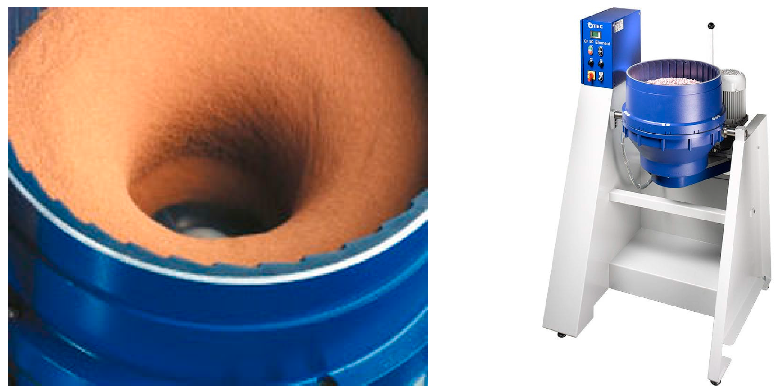
2.1.1. Centrifugal Disc
Centrifugal disc machines were designed to combine the three-dimensional action advantage of a vibratory bowl with the rapid cycle time of the centrifugal barrel. Figure 1 shows an image of the principle of a centrifugal disc machine. The centrifugal force and the rotating action of the disc sends the mass outwards towards the chamber wall. The mass then slows down and returns to the centre to complete the cycle [10]. Centrifugal disc machines are also used for their fast processing and cycle time (typically 10 to 30 min), their capability for batch production and their control in process [1]. However, due to the small capacity of the chamber, the workpiece should not exceed 30 cm in length.
2.1.2. High-Energy Centrifugal Barrel
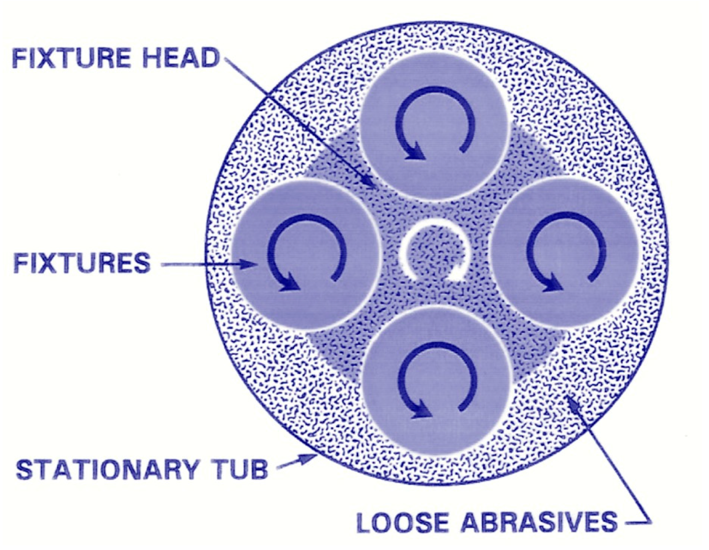
Centrifugal barrel machines often provide finishing results that cannot be achieved in a standard vibratory process. A centrifugal barrel machine is typically comprised of four barrels horizontally mounted between two main drive turrets, as is shown in Figure 2. As the two main turrets rotate, all barrels rotate in the opposite direction of the turret. The capacities of centrifugal barrel machines range from 0.5 cf to 12 cf of processing volume.
This process requires manual loading and unloading as well as parts and media separation. Processes ranging from heavy grinding to fine polishing can be accomplished with centrifugal barrel finishing. Parts can be processed dry in a few select media types in a centrifugal barrel. Both wet or dry, a great deal of heat and pressure are generated within each barrel during this method. Heat must be considered from both a safety and finishing standpoint when centrifugal barrels are utilised.
2.1.3. Fixture Mass Finishing
The purpose of a fixturing method is to hold and give positional and/or rotational variation to the part and its interaction with the media. In the case of a fixed part, immersed in media and rotated at speed (e.g., drag finishing), the part edges and surfaces interact with loose media and a higher force is generated than that developed in conventional mass finishing processes, in which the part is placed randomly in the machine chamber and depends on the media motion to achieve the surface finishing result. Fixture arrangements also promote quicker cycle times. Furthermore, a benefit of the fixturing arrangement is that contact between parts is prevented. The best examples of fixture processes are drag finishing and stream finishing, which give high-quality results with short processing time and high reliability [11]. In this study, automation and optimisation of fixture finishing process were employed to help minimise human intervention.
Drag Finishing
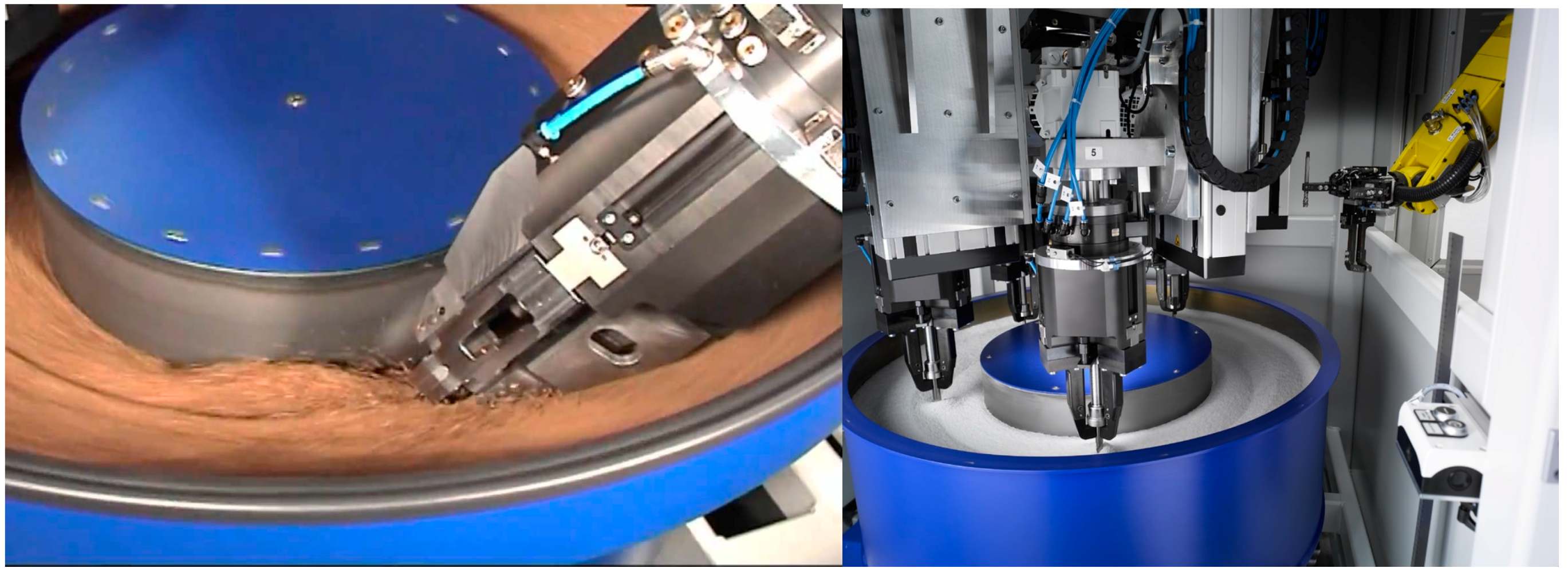
Drag finishing machine technology is used for high-quality and sensitive workpieces that need to be ground or polished without contact between parts; it is available in dry and wet processing. Workpieces are fixed in a special arrangement of workpiece holders. Holders are dragged in circular motion through the container that is filled with the loose abrasive or polishing media. The main spindle is also rotated at different speeds, either clockwise or anticlockwise. Figure 3 shows an image of the drag finishing machine principle.
The mass finishing process is significantly dependent on pressure and speed. In the drag finishing process, the interaction between the high-speed workpiece and media will create high-pressure contacts, leading in a short time to the development of a high-quality surface finish and precise rounding of the part edges, which can otherwise only be obtained by the hand-polishing method. By controlling variables such as immersion depth and rotary speed, it is possible to reach rates of material removal up to 40 times higher than in conventional (vibratory, centrifuge) mass finishing and about 4–5 times faster than high-energy vibratory systems. In addition, the existence of a double drive system with two electric motors allows workpiece edges to be rounded uniformly. This also enhances the tool life. The applications for drag finishing range from aggressive deburring and edge breaking through to high-gloss polishing.
Stream Finishing
Stream finishing is a new method of mass finishing. It is also termed abrasion finishing, though it is not always used as an abrasion process but also for lapping and polishing, depending on the output target. It is able to finish workpieces of length up to 200 mm and weight of 20 kg, including the holder.
Figure 4 shows an image of the principle of a stream finishing machine. The workpiece holder is rotated either clockwise or anti clockwise to allow the workpiece itself to align to the direction of stream flow media. The media flow is generated through the bowl rotation at a specific speed. This configuration helps reduce the effect of transverse forces and lowers the risk of the tool breaking or becoming deformed [1]. Stream finishing is short in processing time, simple in operation, and has excellent reliability. However, despite the high processing force it can generate a fine surface roughness value (Ra) less than 0.03 μm.
The machine shown is able to process six workpieces in unison in a single holder fitted with a quick release mechanism to ensure that the workpiece is finished over the entire surface. Workpiece holders (examples: jaw chuck, drill chuck, collets and gripper) are available possessing different independent features that can rotate around their own axis at the same time. The processing time can be reduced significantly by adapting high-speed rotating workpiece holders (up to 2000 rpm).
2.2. Mass Finishing Media
There are five major materials of loose abrasive media (ceramic, plastic and synthetic, metal, precision, and micro-bite). The internal composition of conventional media is the source of the cutting action, weight, wear, and level of surface finish, all of which define the capabilities of the media.
2.2.1. Shape, Size and Weight
There are approximately 15 different major shapes of loose abrasive media led by triangular, conical, cylindrical, spherical and tetrahedral. Each abrasive media is used for a specific application depending on the workpiece configuration. Shape is an important factor in media selection. The major considerations are that the shape of the loose abrasive media chosen should permit access to all surfaces of the workpiece—meaning any ledges, holes, or other geometric features—for the deburring or finishing operation, and it must allow an easy separation of the media from the workpiece treated at the end of the cycle. In some cases, a mixture of media shapes may be most effective.
The size of loose abrasive media is important for several reasons. It helps to keep the workpieces separate from each other. The right choice can allow the media to reach all surfaces to finish or deburr.
Larger media have a faster cutting rate and produce smoother surfaces on workpieces. However, the use of small media in high-energy methods of mass finishing can improve the surface finish without increasing the cycle time. The weight of the loose abrasive media is another important factor in media selection.
According to [1], heavier media allow faster cutting. However, heavier media apply more pressure than lighter media, which can cause thin or ductile workpieces to bend or distort.
2.2.2. Media Capability
The capability is the ability of the media to deburr corners, edges and other surface requirements with uniformity (constant performance over time). The capability of a media is principally defined by: the machining parameters; the media wear rate; media composition (cutting action, weight, wear and surface finish); the ability to finish a range of workpieces (i.e., shape, size, material); and quality of the finishing. Hard media will work longer, but softer media will cut faster. In terms of media wear, most plastic, abrasive, or ceramic media get smaller over time, which can affect the finishing operation if they are lodged in holes and other recesses, which requires removing them manually.
The efficiency of material removal is strongly determined by the sharpness, hardness and density of the abrasive cutting edges. A media with an aggressive cutting surface will result in a poor surface finish and a media with a fine cutting efficiency will result in a good surface finish. This aspect is essential to understand the capability of the media assessed in this study.
The abrasive grain distribution on the conical shape media has been shown [1] to be largely independent to stock removed. A study directed by Moore [12] investigating the relationship between the volume of workpiece abrasive wear and the mean diameter of the abrasive particles shown that it is possible to find the most economical solution by determining the ratio of media to workload. The results of that study indicate that any change in the optimum ratio can produce a significant effect on the quality of finishing achieved [1]. It can also be noted that, for the range of materials used in the study, increasing the diameter of the abrasive grain increases the volume that is removed from the workpiece. Domblesk and Dennis [13,14] suggested that the particle shape is not the only variable that controls the behaviour of manufactured abrasives. The relationship between particle shape and packing behaviour needs to be understood before the former can be used to accurately predict the wear-rate.
2.3. Additive Manufacturing (AM) Artefact Design for Finishing
2.3.1. Design Constraints of Part to Be Finished
The geometry for the finishing artefact is influenced by three main factors:
- ➢
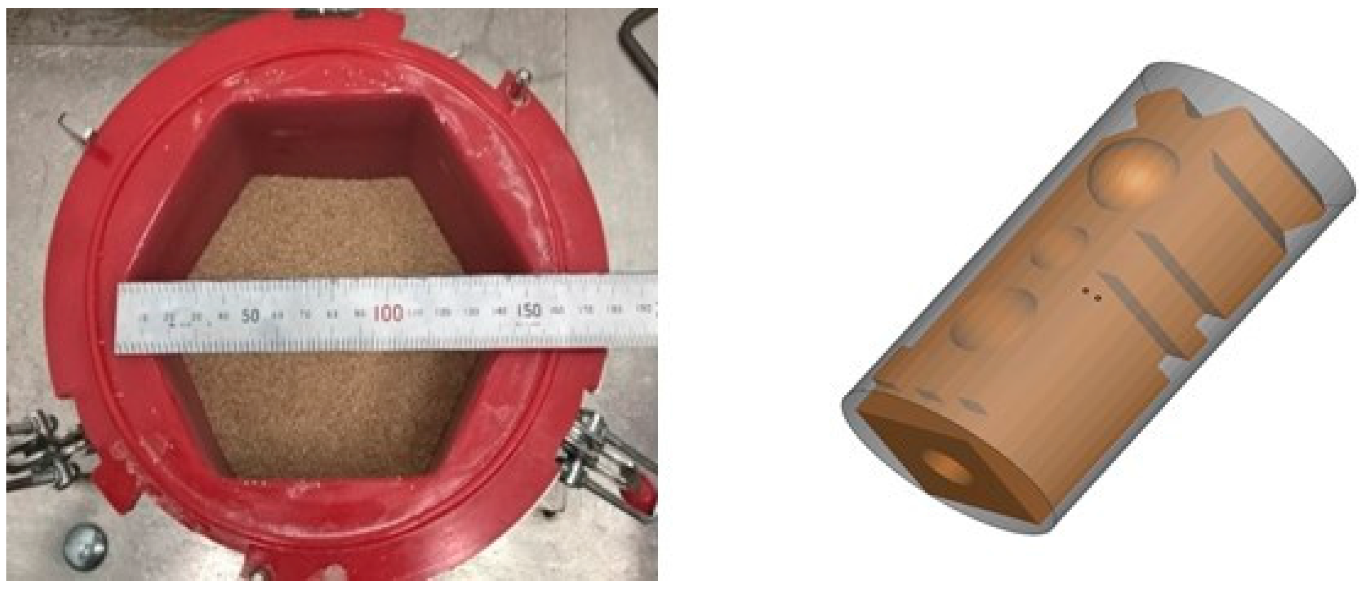
- Design space: The artefact should be bound within a Ø40 mm × 80 mm design space. This was required so that the artefact could move freely within the high-energy machine, as shown in Figure 5.
- ➢
- Selective Laser Melting (SLM) using Renishaw AM250. Design points to take into account:
- Build direction
- Minimum feature size (refer to design features)
- Build supports
- Size of part (SLM machine can build parts larger than this design space)
- ➢
- Design features: The part had to include a variety of design features within a compact design space. Including: thru holes, free-form surfaces and sharp corners.
2.3.2. Artefact Design Summary
- ➢
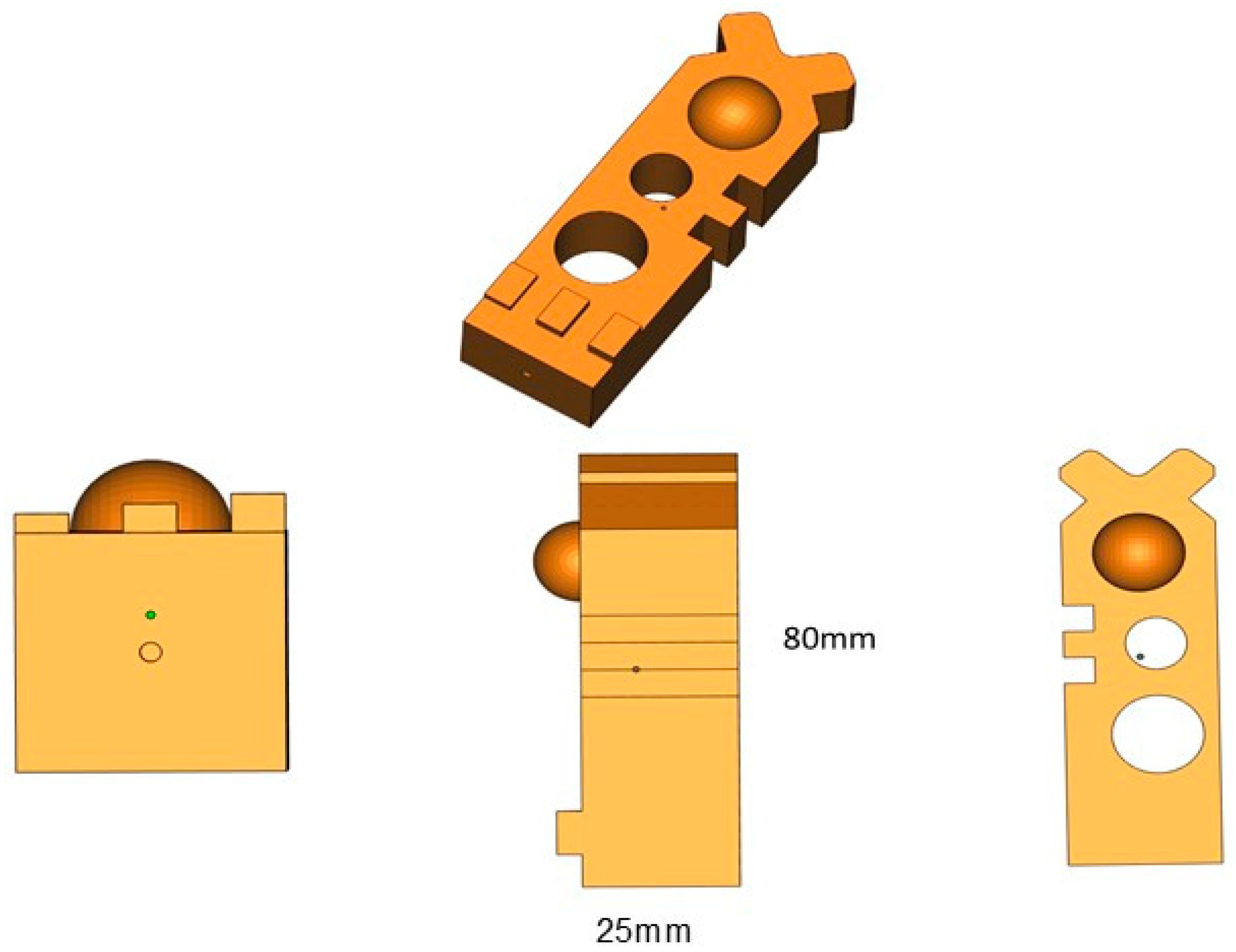
- Part Size: 25 mm × 25 mm × 80 mm
- ➢
- Design Features (Figure 6)
- Free-form surface
- 2 × Angled surfaces (45 degrees to horizontal)
- Concave and convex features
- 2 × cut out sections (5 mm × 5 mm × 25 mm)
- 10 mm and 15 mm thru holes
- 3 × blocks (1, 2 and 3 mm height)
- Flat surface (25 mm × 65 mm)
- ➢
- Fixturing point:
- 2 mm pilot hole for internal thread.
2.4. AM Build Strategy
- Build height: 32.5 mm
- Build time: ~40 h
- Supports: Minimal supports are required for this build
- Machine: Renishaw AM250
- Parts per build: Maximum of 10 parts per build
The base materials used in this study were Ti-6Al-4V. All parts were built using a Renishaw AM250 selective laser melting (SLM) machine. According to a complex part manufacturing setting, the vertical strategy is used to create a Ti thin section sample with layer thickness of 30 μm. The Ti-6Al-4V powder diameters used for experiments were located within the range of 10–20 μm and the composition conformed to the standard, Table 1. Argon gas is used during the process in order to protect the oxidation of surfaces. The gas is supplied through the powder projection nozzle of the additive manufacturing machine. The operating parameters used for the build samples are listed in Table 2. The average surface roughness of the base material is around 20 μm. The build configuration on the plate is shown in Figure 7.
2.5. Experimental Design and Setup
The experimental analyses were carried out on the comparison between different mass finishing processes of drag, stream, disc centrifuge and high-energy centrifuge. The AM metal parts in Stainless Steel 316 were used in this investigation with average surface roughness values, following build and sand blasting, of 1.7 μm (±0.15 μm). The liquid compound SC15 was used for the tests. The proposed techniques were compared according to the 2D surface finish parameters (Ra, Rz, and Rt) and areal surface finish parameters (Sa, Sz, and St) achievable at constant processing time intervals of 30, 60, 90 and 120 min. The experimental parameters are summarised in Table 3.
Three different media were used during the finishing process: plastic (OTEC DS, conical), ceramic (OTEC KM10 and KXMA24, tetrahedral) and Al Oxide (spherical). The experimental tests that involved drag finishing were performed by setting the head speed at 50 rpm, and varying the spindle speed over the values of 20, 40, and 80 rpm. In the case of stream finishing, the experimental tests were performed by setting the spindle speed at 30 rpm, and changing bowl speed over the values of 20, 40 and 60 rpm. The position of the workpiece in the bowl was selected carefully at the maximum stream flow region. In both cases full immersion of the workpieces were employed to ensure better performance results. The work holding design has been fabricated according to the workpiece geometry. The angled head was selected to be zero in all operation processes in order to ensure optimal contact between the media and workpiece.
The experimental tests relating to the centrifugal disc finishing, were performed by varying the rotating speed within the values of 150, 200 and 250 rpm, while the rotation speed kept at 200 rpm for the high-energy centrifuge.
The 2D surface roughness of the workpieces was inspected by tracing the surface using a Talysurf surface instrument at several positions along the surface before and after finishing processes (stress force = 0.75 mN; standard cut-off = 0.1 mm; transverse length = 0.8 mm; amplitude height 2.5 μm; stylus speed = 0.5 mm/s) Three surface roughness measurements were performed on the workpiece surface at each time interval; the average of the group results are presented in this study.
A three-dimensional optical profiler instrument was used to assess the morphology of the specimen before and after the machining process. The optical profile instrument (GFM) uses the phase measurement fringe projection technology method and is a good tool for characterising surface height variations and quantifying the amplitude of peaks and valleys (roughness profile) resulting from the machining process.
3. Results
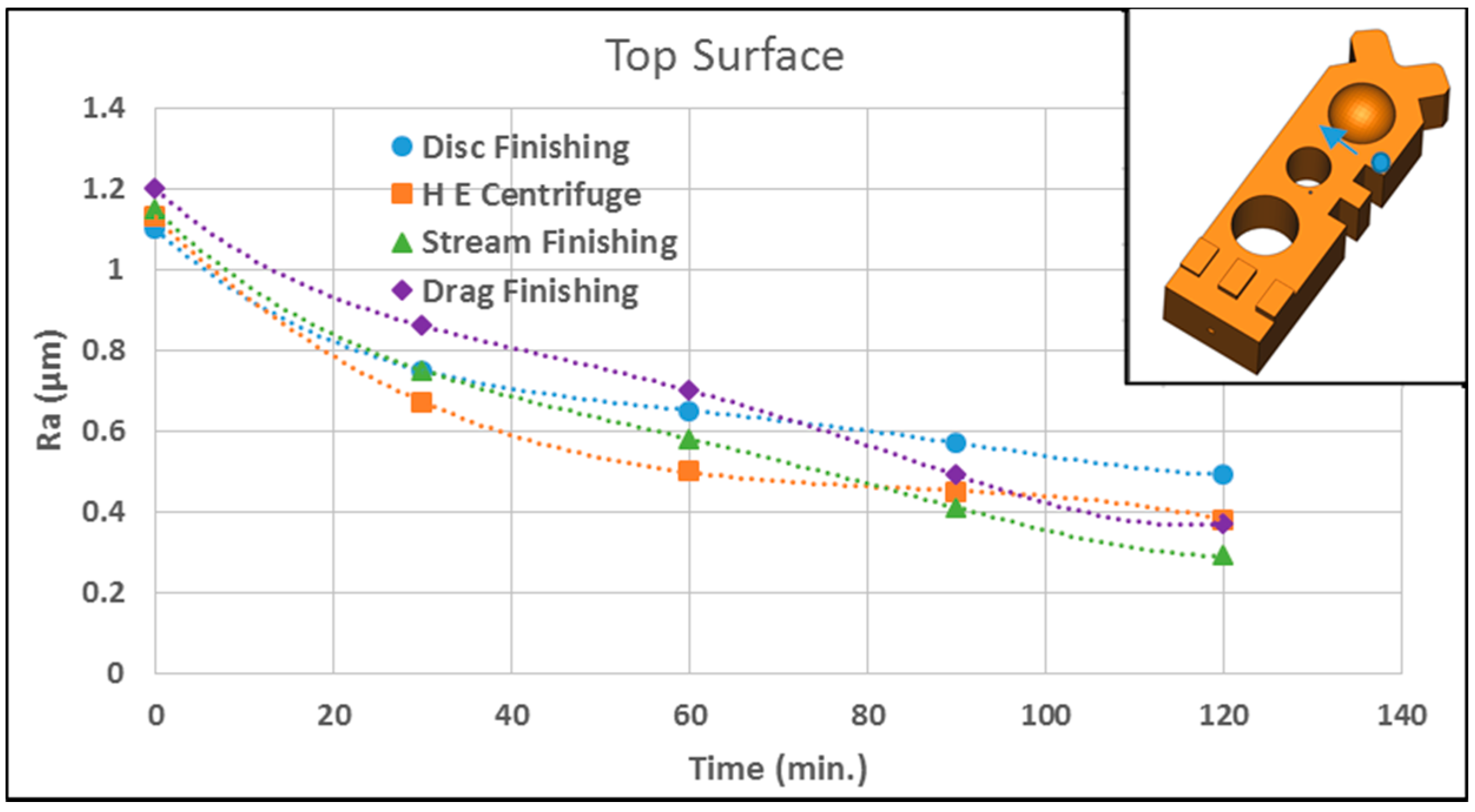
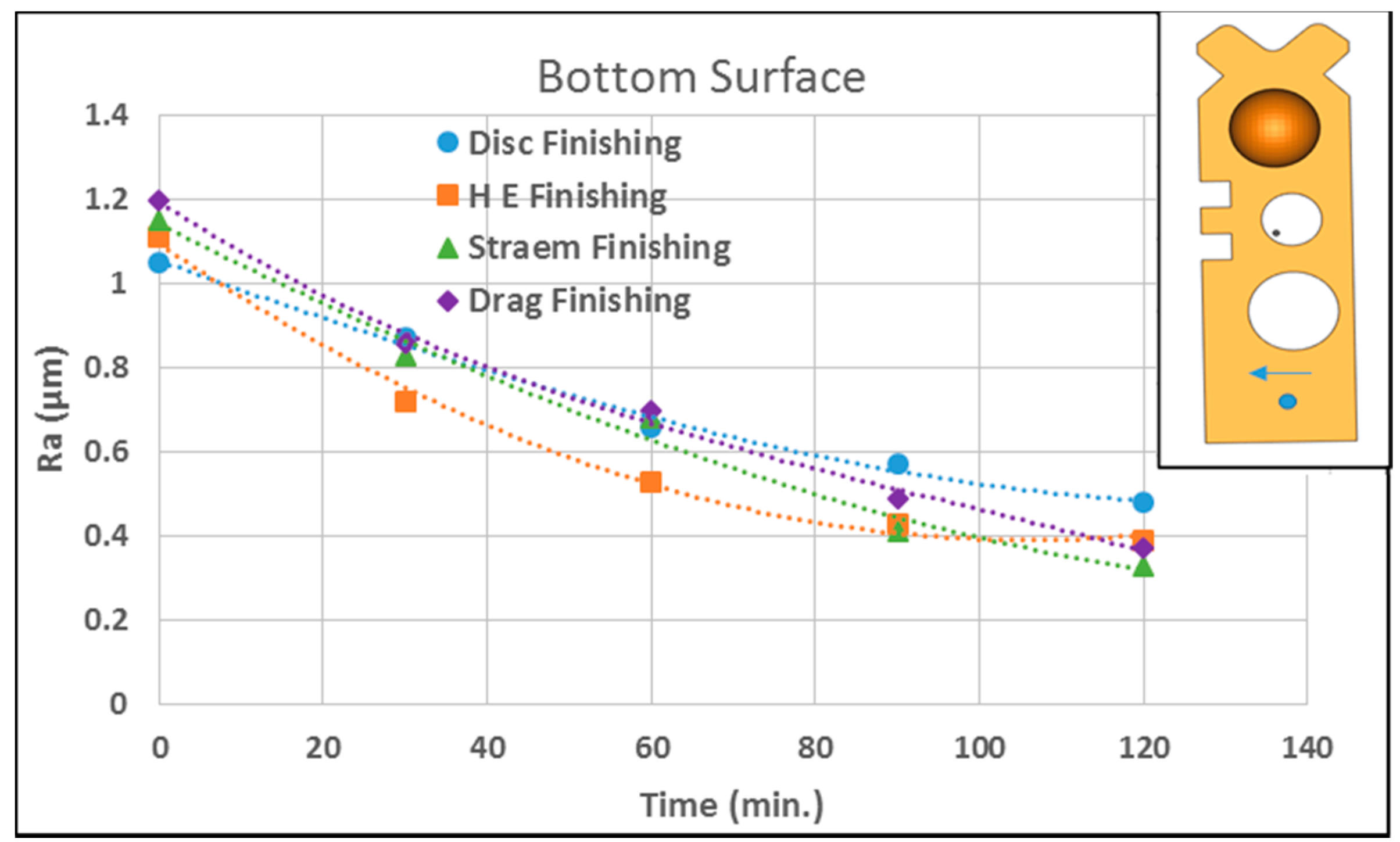
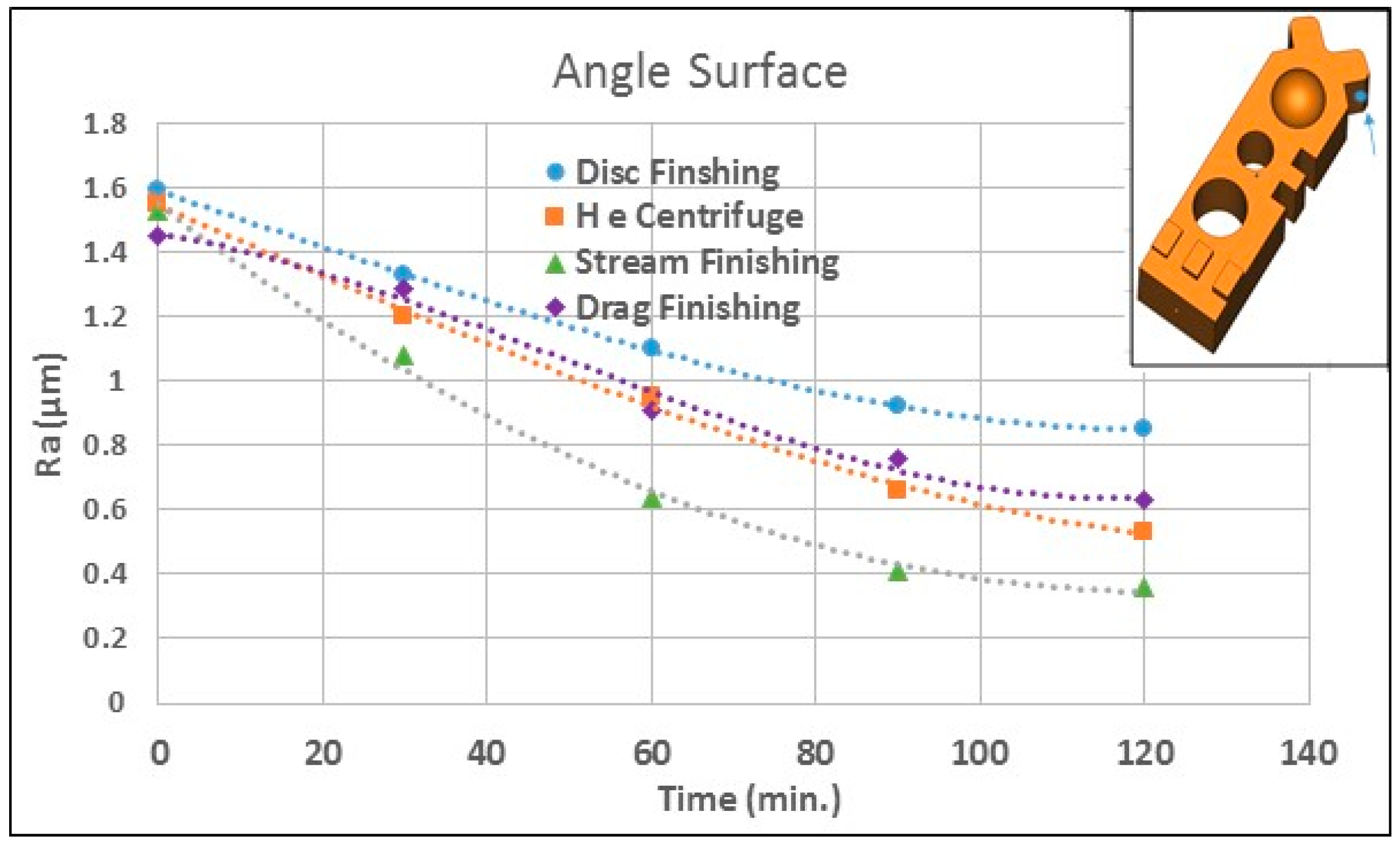
The results of the comparative evaluation between the four advanced finishing process techniques (drag, stream, disc, and high-energy (HE) centrifuge) are summarised in Figure 8, Figure 9, Figure 10 and Figure 11, which provide the surface roughness values at different stages of the manufacturing process.
The results show that each of the finishing processes improved the starting workpiece morphology by progressively cutting the peaks and obtaining a smooth surface based on the setting of the operational parameters. The surface roughness profile (Figure 8 and Figure 9) shows that the valley surfaces remain largely unaffected by the finishing process, this may be attributed to the media size, which cannot reach these regions except in stream finishing where fine spherical Al Oxide media was employed. It is clearly noticed, the relatively high spindle head speed of drag and stream, reduces the average surface roughness over the processing time regardless of the abrasive tool. However, the results demonstrated that the rate at which surface roughness decreases over the maximum cycle time is related to the AM part orientation. Table 4 shows the decreases in surface roughness using various mass finishing processes at maximum processing time of 120 min.
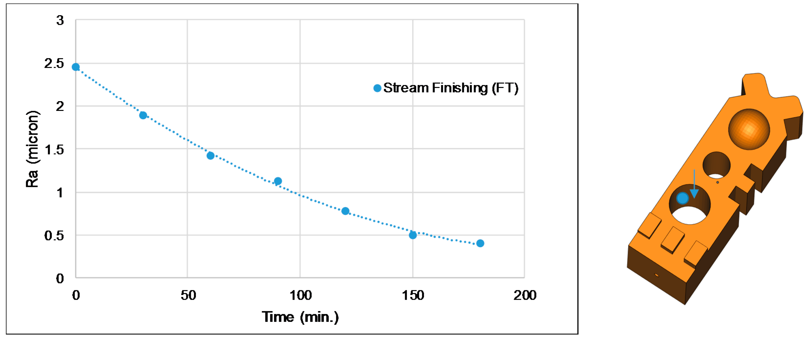
Mass finishing processes of the external surfaces, and easily accessible internal surfaces, to specification can be accomplished by traditional processes. However, most of these processes are inflexible and provide little control, nor can they access internal surfaces of complex shapes. For these type of challenges stream finishing can be a viable solution. Figure 12 shows the surface roughness (Ra) values of the internal hole surface as a function of processing time using the stream finishing process and Al Oxide media. It is clear that the surface roughness decreases to the value of 0.41 µm at the maximum processing time of 180 min.
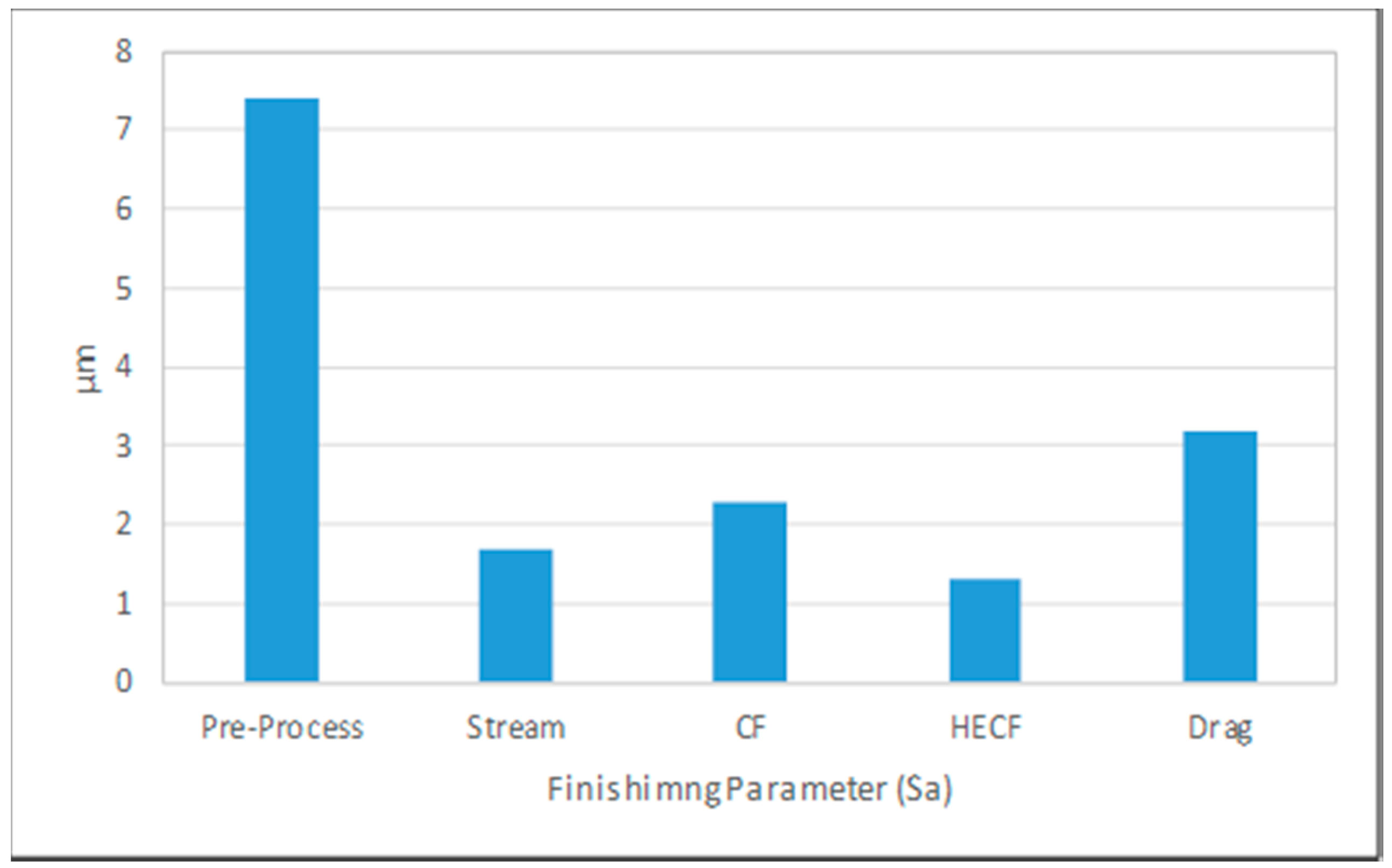
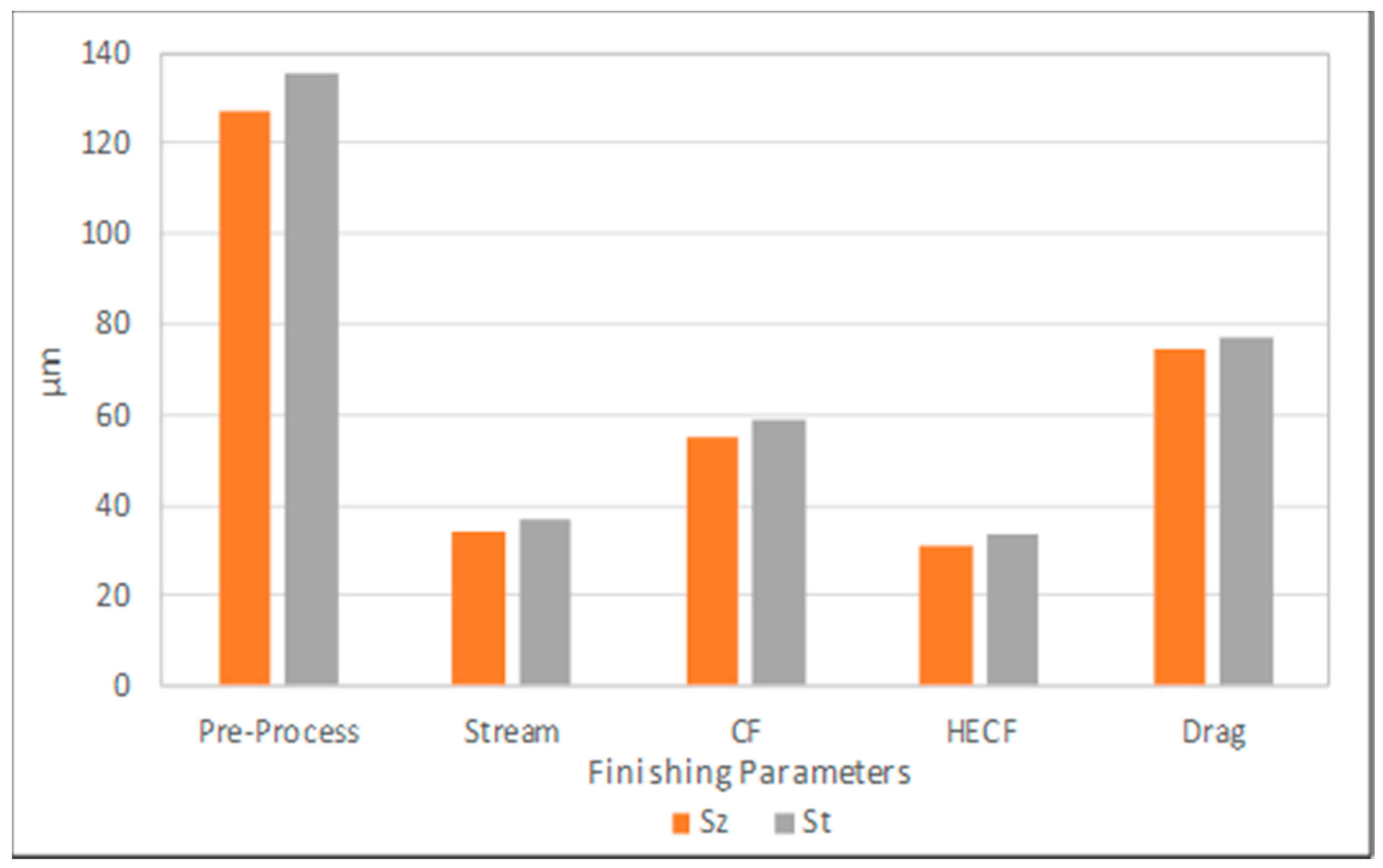
Figure 13 and Figure 14 show the comparison of areal surface roughness (Sa, Sz, and St) of the side surface at maximum processing time of 120 min using different finishing technologies and media grade (ceramic media have been used for disc, HE centrifuge, and drag finishing processes and Al Oxide media for the stream finishing process). Figure 13 shows that the decreases in surface roughness Sa of the side surface using drag, stream, disc, and HE centrifuge at maximum processing time of 120 min were 3.2, 1.7, 2.3, and 1.3 µm, respectively. Similarly, in Figure 14 the HE centrifuge achieved the lowest Sz, and St values followed by stream, centrifuge and drag finishing processes.
Figure 15 shows an example of the 3D mapping assessment of AM part morphology using stream and HE centrifuge finishing processes. The 3D maps were obtained before and after 120 min of finishing. The results demonstrated that, after 180 min, the built layer peaks of the workpieces are very thin when processed with stream finishing and completely disappear with the HE centrifuge. This suggests that the HE centrifuge finishing process with ceramic media has the most aggressive uncontrolled effect on the AM part, which may cause over-finishing of the workpiece surface in the context of poor edge/radius retention, feature losses and breaching of tolerance criteria. This over-finishing may cause a failure of the workpiece due to the high surface erosion and may force a re-design.
Despite the wide versatility of mass finishing processes, some potential process limitations should be noted. For the non-controllable finishing processes (disc and HE centrifuge), it can be difficult to selectively treat certain areas of the part to the exclusion of other areas, which might have critical dimensional tolerance requirements. Unless masked or fixtured, all exterior areas of the part will be affected by the process to a greater or lesser degree, with effects on corners and edges being more pronounced than those on flat areas, and with interior holes, channels, and recesses being relatively unaffected in the more common processes. However, care must be exercised in media size, shape selection, machining parameters and maintenance to prevent media lodging in holes and recesses, which might require labour-intensive manual removal and prohibit further abrasive/polishing action. Some parts have shapes, sizes, or weights that may prevent them from being finished in some traditional mass finishing processes because of the risk of impingement from part-on-part contact. However, drag and stream finishing processes can be a viable solution for such challenges.
4. Process Optimisation System of Drag Finishing
For this study, the core of the process optimisation system was based on readily available and well-understood proprietary statistical and mathematical software packages. The complete optimisation tool used ANOVA, the Taguchi experimental methodology and the response surface methodology (RSM) coupled with a MATLAB—Graphical User Interface (GUI). These tools were used to develop a surface roughness prediction model of advanced mass finishing technology under various machining parameters conditions. The model can then be used to estimate process parameters needed to achieve a desired roughness of a workpiece.
The usefulness of the system is not restricted to optimisation in the production context. It can also be used as design tool or as a production planning aid. As a design tool it can provide optimal parameter sets for materials new to the process or not in common use, and as a planning tool to plan production cycles to match related operations and to avoid misalignment of outputs with other processes, or to ensure maximum machine utilisation or indeed both. Further, it has potential to be of great benefit to machine tool salespersons and production engineers in the field.
4.1. The Taguchi Method
Taguchi is a statistical experimental tool designed to calculate a single or multiple groups of data (variable) to find the optimal and regularity in the operating environment (response). It is also used to identify the controllable and un-controllable factors in order to minimise the effect of noise factors. The orthogonal array (L8) matrix is designed to investigate the effect of each factor independently from others in order to reduce time and cost. The main objective is to identify the ranks of each factor that affect the mean response.
The statistical evaluation of performance required use of a signal-to-noise (S/N) ratio approach to measure deviation of the quality characteristic from the design value.
The S/N ratio can be used instead of the average value for the evaluation characteristic in the optimum variable analysis [15,16,17].
The S/N ratio approach can be divided into three quality tools: “the smaller the better”, “the nominal the better”, and “the higher the better” when characterizing the response quality for engineering processes. In this study, “the smaller the better” surface roughness was considered in investigating the influence of machining variables in the drag finishing process. The S/N ratio of “the smaller the better” quality characteristics can be defined by Equation (1):
where (Y2)/n is the mean of the square of measured data at i test and n is the number of repetitions.
Experimental Design and Setup
Experimental investigations were carried out using a drag OTEC machine. AM parts were used in the experiments with average surface roughness values of 1.7 µm (±0.15 µm). Liquid compound SC15 at a constant dosing rate of 3%. Ceramic and plastic media KM10 were employed in the tests. All experiments were performed at a constant processing time of 90 min.
The machining parameters were selected as follows: the experimental tests were performed with variable spindle speed, DSS within range (10 ≤ DSS ≤ 80) rpm, the head speed, DHS various within range (10 ≤ DHS ≤ 60).
Another important parameter that should be considered in the drag is the angle of the head holding the workpiece. Due to the shape of the AM part, the angled head was selected to be zero (vertical position) in all tests using a special holding arrangement to ensure continuous flow of media on the workpiece surface during operation.
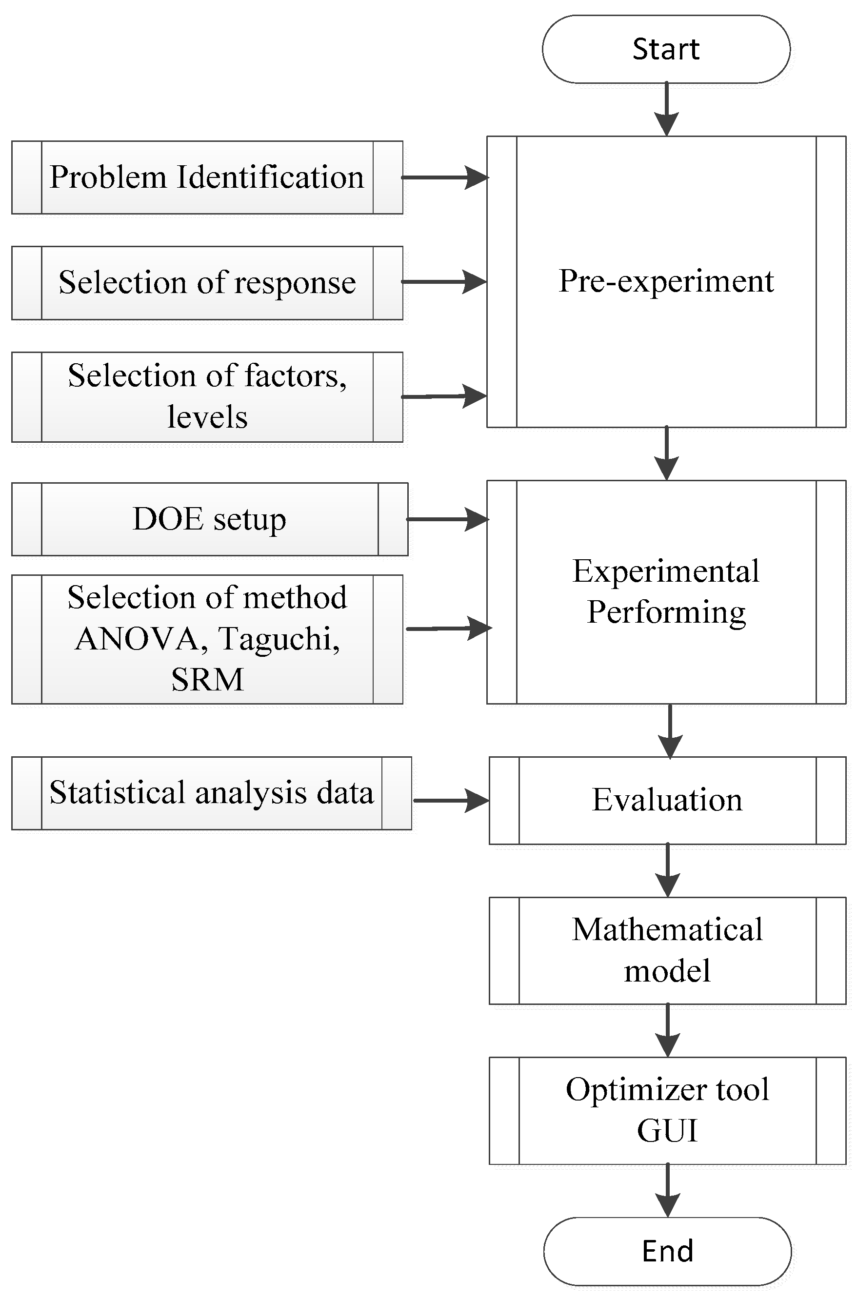
Areal Sa surface roughness tests were conducted using a three-dimensional optical profiler instrument to investigate the morphology of the specimen before and after the machining process. Three surface roughness measurements were performed on each workpiece material, the average of the group results is presented in this study. However, this work can be extended to include the process optimisation system of Taguchi, ANOVA, and surface response methodologies to develop a mathematical model used to predict the surface roughness of the AM component, as shown in Figure 16. In general, the process optimisation system is based on 10 steps of planning, performing and evaluating results of a matrix of experiments to determine the performance levels of control parameters [18].
4.2. Results
Analysis of the Signal-to-Noise (S/N) Ratio (Taguchi Method)
The S/N number represents the ratio between desirable and non-desirable values. The process parameter with the highest value has the most significant effect on the optimisation process [15]. In this study, the Taguchi optimisation process was selected with six degrees of freedom, three factors and two levels. The process parameters and their levels in the drag process are presented in Table 5.
The process variables and their levels were set over a wide range of parameters in order to cover a comprehensive performance capability of the finishing processes. A set of experiments were conducted using the dag finishing process and the L8 orthogonal array with eight experiments. Table 6 shows the DOE layout and results from the drag finishing processes.
Due to different units within the process parameters, each factor was coded with two levels. The influence of the interaction between variables is neglected in the Taguchi method. Regardless of the machining process characteristics, the greater the S/N value, the better the performance. Based on the S/N ratio analysis, the optimal drag finisher performance for best surface roughness was obtained at 80 rpm spindle speed (level 2), 50 rpm head speed (level 2), and Ceramic media (level 1).
Optimal finishing conditions for the drag process are shown in Table 7. Table 7 indicates that the strongest effect on the finishing process is given as rank 1 and is associated with the media, followed by rank 2 (the head speed), while rank 3 (the spindle speed) has the weakest effect on the process.
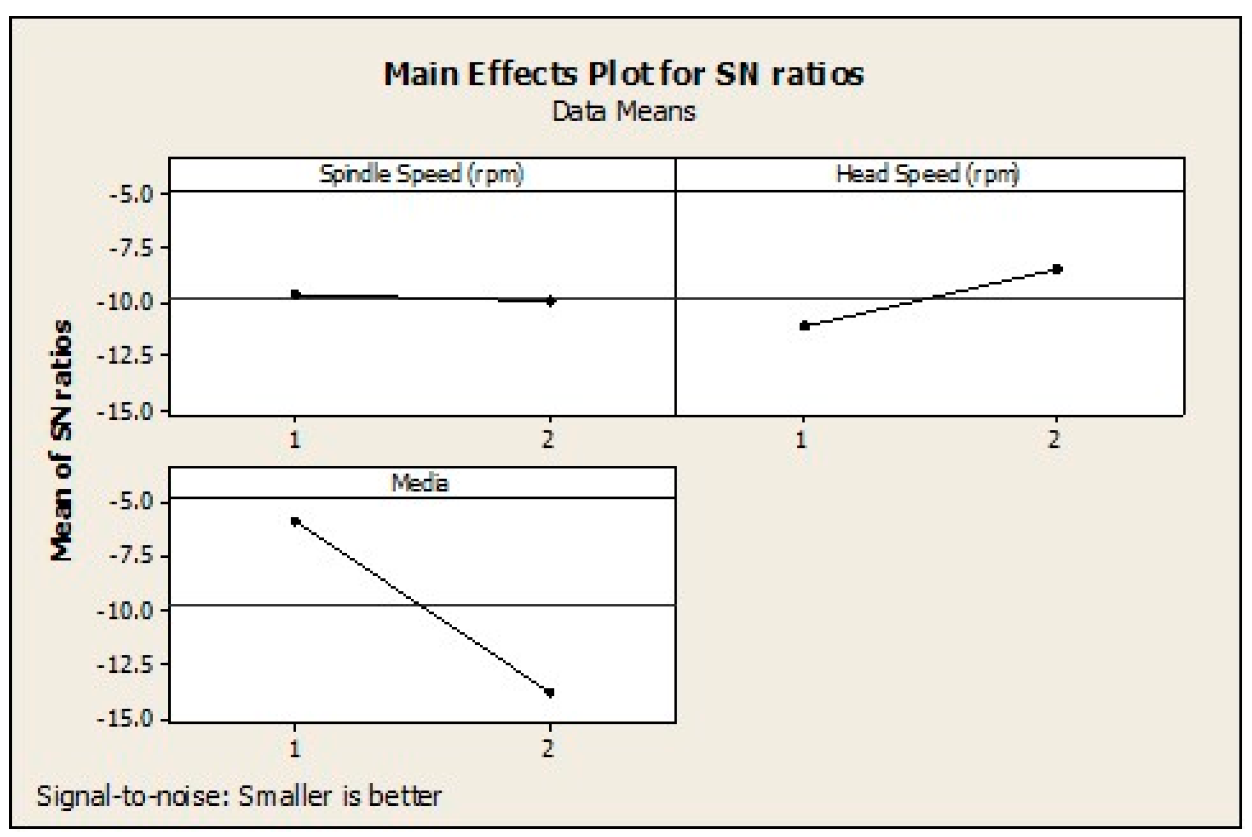
Figure 17 shows the principal variations caused by changes to the S/N ratio. The strongest influence of the factor on the finishing process is measured by differences values. The factor that contributes to the higher difference in the mean S/N ratio over the selected design control factor, the more significant the impact. Optimal finishing conditions of design control factors of drag finishing process can then be determined from the S/N response graphs. As displayed, the media type shows the higher slope of the S/N ratio, which identifies the significant impact on the finishing process. The results show that the surface roughness decreases with the increasing drag head speed. The S/N ratios also identify that spindle speed had the least influence of the three factors.
5. Conclusions
A comparison of results obtained using spindle finishing (drag and stream), centrifugal disc finishing and HE centrifuge processes using conventional abrasive granulate (Al Oxide and ceramic) media on the surface finish of an AM component has been undertaken. The results for the cases studied suggest that the stream finishing process is most efficient in reducing the surface roughness followed by HE centrifuge and drag finishing, then finally the centrifugal disc finishing process. However, it is to be noted that the media used in the drag machine was not the optimal type for this study.
The abrasion potential of the drag and stream finishing processes is high, especially when operated at the fastest spindle speed of 80 rpm and bowl speed 60 rpm, respectively. This may be attributed to the different hydrodynamic behaviour of the abrasive media in the processing medium. The impacts with abrasive media take place at high speed, which is generated from the difference between the workpiece rotating speed and the quasi-static abrasive media for the drag finishing process and from the difference between the workpiece rotation speed and abrasive media rotation flow for the stream finishing process. In the centrifugal finishing process, the workpiece is immersed into the abrasive media and travels with the flow.
Despite the high rotation speed of the disc in the centrifugal finishing process (250 rpm), the relative speeds between the abrasive media and the workpiece are expected to be lower because it only comes from the resultant difference in the system force acting on the abrasive medium. This speed is much higher in the HE centrifuge process, resulting in high-energy contact ,which alters the AM surface texture substantially, not only reducing surface peaks but generating a surface in which the positioning of the peaks has been altered appreciably.
However, it is the impact speed together with the mass of abrasive media that develop the kinetic energy that is released onto the workpiece surface. It follows that based on the abrasive media type, the abrasion potential of different technologies is determined by the impact speeds/force between the abrasive media and the workpiece. The energy of such interactions is converted to strain energy once impacted on the workpiece surface.
Furthermore, the strain energy release must be high enough in order to achieve a critical value equal to the resistance of crack growth, thereby leading to surface plastic deformations by micro-cutting. This higher energy should be accurately controlled to avoid problems such as the over-finishing of the workpiece surface. Over-finishing may cause a failure of the workpiece due to the massive surface erosion.
The reduced residual material after machining, low energy requirements, and quick cycle times make the fixed part processes of drag and stream industrially sustainable and promising in different manufacturing areas where high quality and performance are crucial requirements.
In this study, an experimental investigation has been undertaken with statistical analysis to determine the effect of varying DSS, DHS and media in the drag finishing process on the surface roughness values of AM components, using the Taguchi method. Taguchi analysis is responsible for investigating the rank and the level of factors that have a significant effect on the response. Taguchi statistical analysis of the drag finishing process suggested that the control factors that minimise surface roughness were ceramic media, DHS (level 2), 80 rpm and DSS (level 2), 50 rpm.
The study has identified the need to further characterise selected high-energy mass finishing processes for more realistic, and hence potentially more challenging, AM parts. The study has highlighted the potential for the future development of a two-stage finishing system.
Author Contributions
The research was conceived and completed jointly by Mikdam Jamal and Michael N. Morgan. The Manufacturing Technoogy Centre and partners, and Liverpool John Moores University technical staff assisted in the completion of experiments and surface measurements.
Conflicts of Interest
The authors declare no conflicts of interest.
References
- Gillespie, L.K. Mass Finishing Handbook; Industrial Press: New York, NY, USA, 2006; ISBN 9780831132576. [Google Scholar]
- Mediratta, R.; Ahluwalia, K.; Yeo, S.H. State-of-the-Art on Vibratory Finishing in the Aviation Industry: An Industrial and Academic Perspective. 2015. Available online: link.springer.com/article/10.1007/s00170-015-7942-0 (accessed on 1 July 2017).
- Salvatorea, F.; Grangea, F.; Kaminskia, R.; Claudina, C.; Kermoucheb, G.; Recha, J.; Texierc, A. Experimental and Numerical Study of Media Action during Tribofinishing in the Case of SLM Titanium Parts. 2017. Available online: www.sciencedirect.com/science/article/pii/S2212827117304341 (accessed on 1 August 2017).
- Walton, K.; Blunt, L.; Fleming, L. The Topographic Development and Areal Parametric Characterization of a Stratified Surface Polished by Mass Finishing. 2015. Available online: iopscience.iop.org/article/10.1088/2051-672X/3/3/035003 (accessed on 1 August 2017).
- Zaki, N. Mass finishing considerations for optimum productivity. Metal Finish. 1992, 90, 50–54. [Google Scholar]
- Brust, P.C. Surface Improvement by Vibratory Cascade Finishing Process; Transactions-North American Manufacturing Research Institution of SME: Lincoln, NE, USA, 1997; pp. 93–98. [Google Scholar]
- Davidson, D.A. Developments in mass finishing technology. Metal Finish. 2003, 101, 49–56. [Google Scholar] [CrossRef]
- Domblesky, J.; Evans, R.; Cariapa, V. Material removal model for vibratory finishing. Int. J. Prod. Res. 2004, 42, 1029–1041. [Google Scholar] [CrossRef]
- Davidson, D.A. Surface finishing reaches new heights: Mass media finishing techniques can improve aircraft part performance and service life. Metal Finish. 2005, 103, 25–28. [Google Scholar] [CrossRef]
- Cariapa, V.; Park, H.; Kim, J.; Cheng, C.; Evaristo, A. Development of a metal removal model using spherical ceramic media in a centrifugal disc mass finishing machine. Int. J. Adv. Manuf. Technol. 2008, 39, 92–106. [Google Scholar] [CrossRef]
- Telljohann, D. Stream Finishing Process and Application. 2014. Available online: http://www.otec.de/ (accessed on 1 August 2017).
- Moore, M.A.; Douthwaite, R.M. Plastic deformation below worn surfaces. Metall. Trans. A 1976, 7, 1833–1839. [Google Scholar] [CrossRef]
- Domblesky, J.; Cariapa, V.; Evans, R. Investigation of vibratory bowl finishing. Int. J. Prod. Res. 2003, 41, 3943–3953. [Google Scholar] [CrossRef]
- De Pellegrin, D.V.; Stachowiak, G.W. Assessing the role of particle shape and scale in abrasion using ‘sharpness analysis’: Part II. Technique evaluation. Wear 2002, 253, 1026–1034. [Google Scholar] [CrossRef]
- Phadke, M.S.; Kackar, R.N.; Speeney, D.V.; Grieco, M.J. Off-line quality control in integrated circuit fabrication using experimental design. Bell Syst. Tech. J. 1983, 62, 1273–1309. [Google Scholar] [CrossRef]
- Pignatiello, J.J., Jr. An overview of the strategy and tactics of Taguchi. IIE Trans. 1988, 20, 247–254. [Google Scholar] [CrossRef]
- Pease, G. Taguchi Methods: A Hands-on Approach to Quality Engineering; Addison Wesley: New York, NY, USA, 1993. [Google Scholar]
- Jamal, M.; Morgan, M.N.; Peavoy, D. A digital process optimisation, process design and process informatics system for high energy abrasive mass finishing. Int. J. Adv. Manuf. Technol. 2017, 92, 303–319. [Google Scholar] [CrossRef]
Figure 1.
Centrifugal disc machine principle (LJMU).

Figure 2.
High-energy centrifugal barrel machine principle showing media and parts in each barrel.
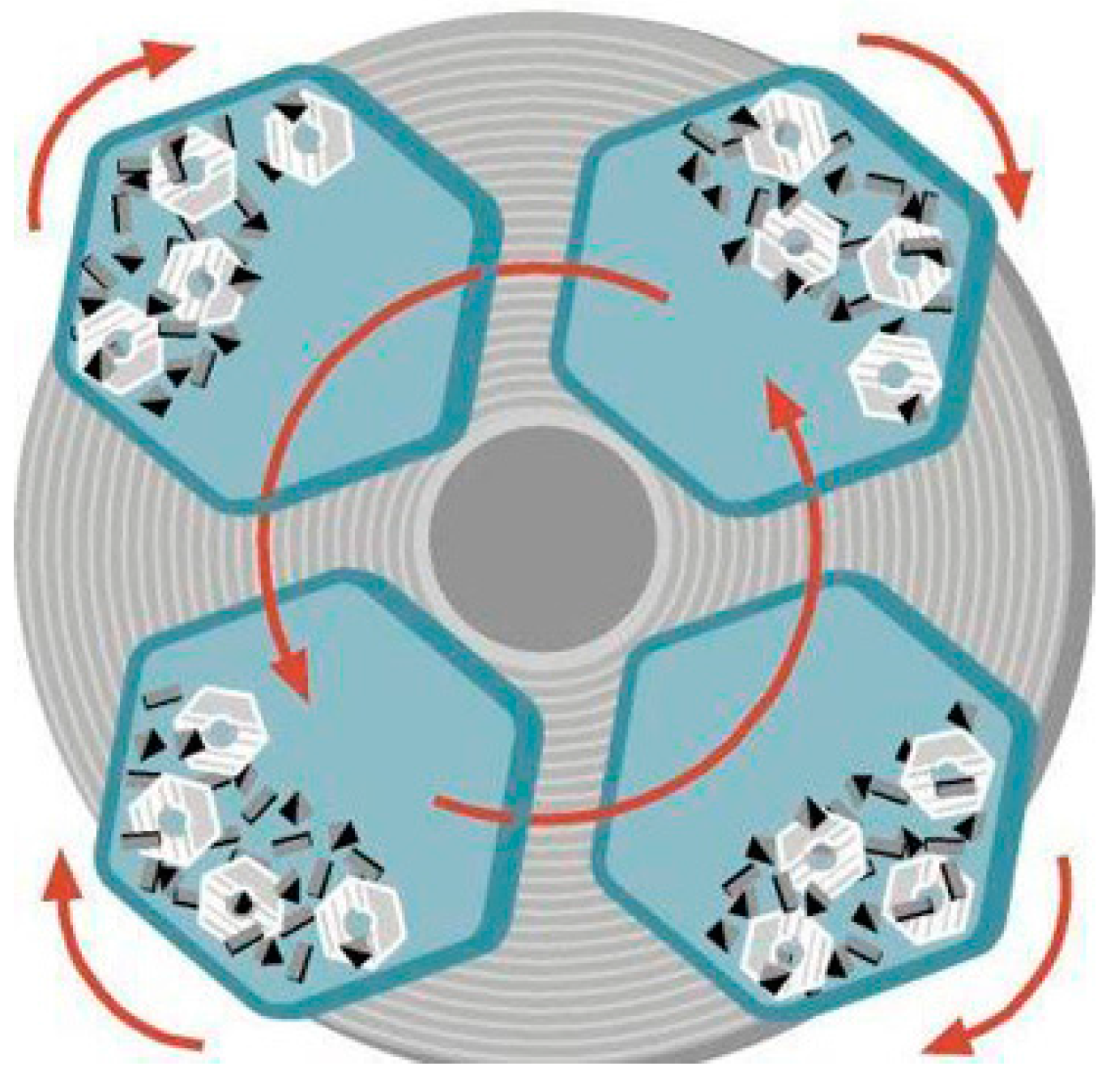
Figure 3.
Drag finishing machine principle.

Figure 4.
Stream finishing machine principle (LJMU).

Figure 5.
High-energy centrifuge and design space for part (grey shaded area).

Figure 6.
The resultant additive manufactured (AM) artefact design features.

Figure 7.
AM building strategy (showing eight parts).
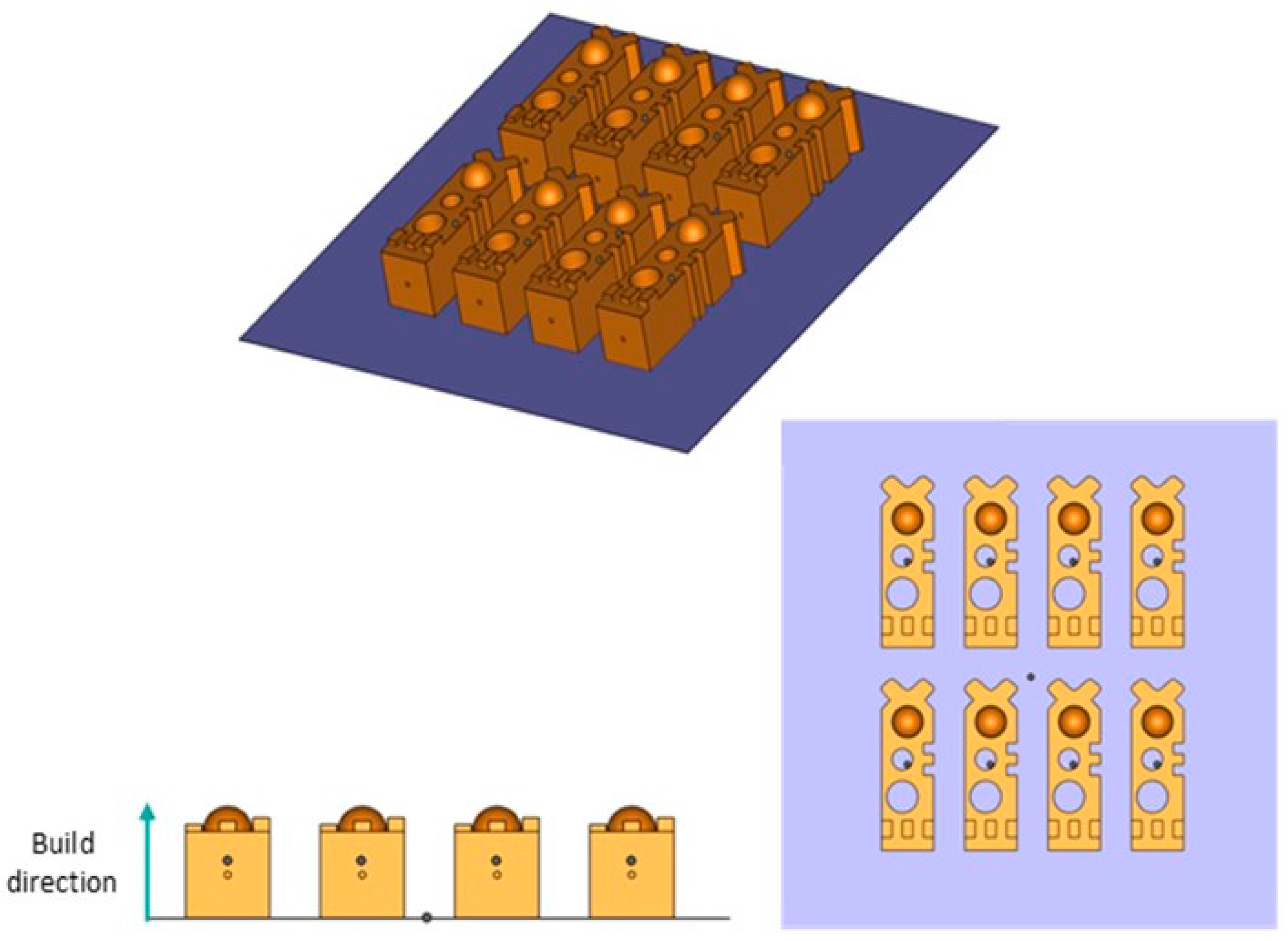
Figure 8.
Surface roughness comparison on bottom surface (blue arrows show direction of measurement).
Figure 8.
Surface roughness comparison on bottom surface (blue arrows show direction of measurement).

Figure 9.
Surface roughness comparison on top surface (blue arrows show direction of measurement).

Figure 10.
Surface roughness comparison on angle surface (blue arrows show direction of measurement).
Figure 10.
Surface roughness comparison on angle surface (blue arrows show direction of measurement).
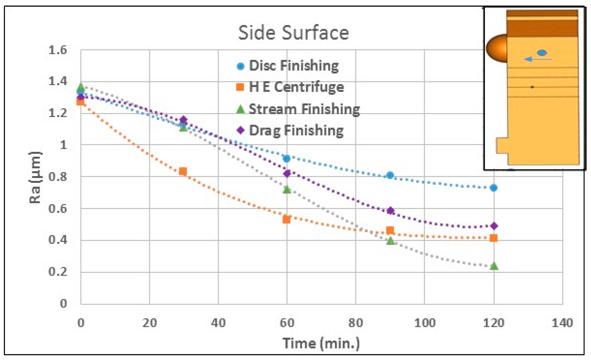
Figure 11.
Surface roughness comparison on side surface (blue arrows show direction of measurement).
Figure 11.
Surface roughness comparison on side surface (blue arrows show direction of measurement).

Figure 12.
Stream finishing internal surface roughness values as a function of processing time (blue arrows show direction of measurement).
Figure 12.
Stream finishing internal surface roughness values as a function of processing time (blue arrows show direction of measurement).

Figure 13.
Sa comparison at maximum processing time of various mass finishing processes.

Figure 14.
Sz and St comparison at maximum processing time of various mass finishing processes.

Figure 15.
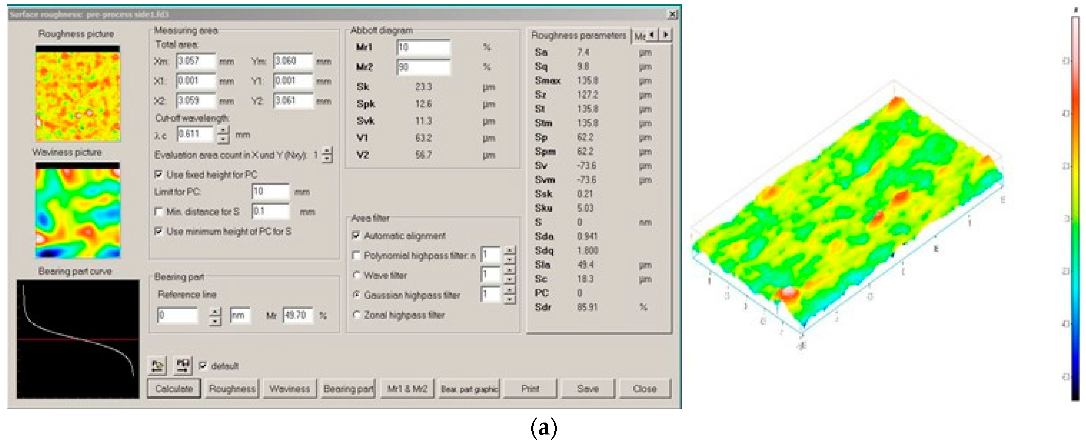
A 3D map assessment of AM part morphology before and after finishing processes. (a) Pre-processing 3D areal surface roughness parameters; (b) Stream finishing 3D areal surface roughness parameters; (c) HE centrifuge finishing 3D areal surface roughness parameters.
Figure 15.
A 3D map assessment of AM part morphology before and after finishing processes. (a) Pre-processing 3D areal surface roughness parameters; (b) Stream finishing 3D areal surface roughness parameters; (c) HE centrifuge finishing 3D areal surface roughness parameters.

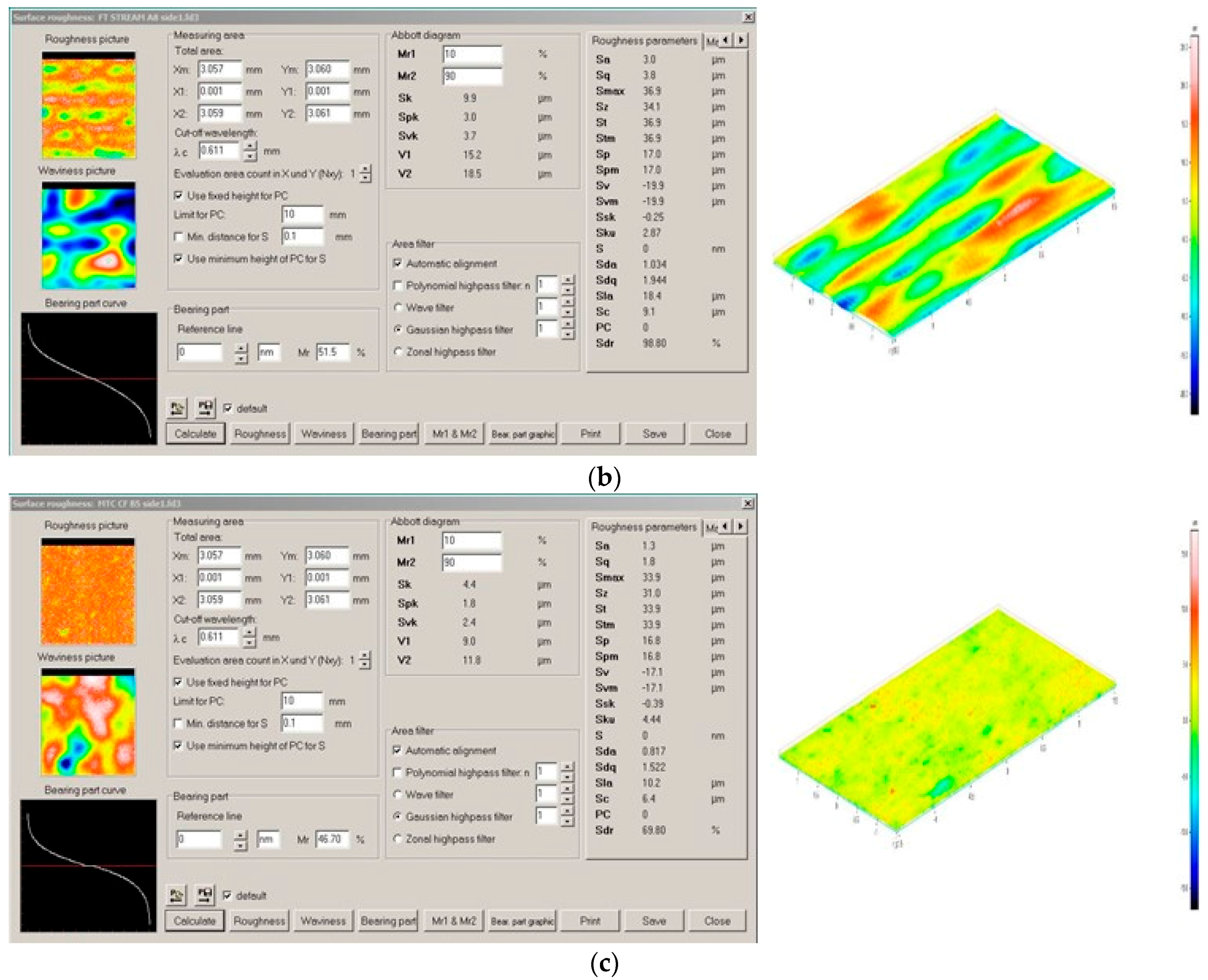
Figure 16.
A schema of the process optimisation system.

Figure 17.
Effect of drag process parameters on surface roughness.


Table 1.
Chemical compositions for Ti-6Al-4V used in the study (wt %).
| Al | V | O | N | C | H | Fe | Ti |
|---|---|---|---|---|---|---|---|
| 5.5–6.75 | 3.5–4.5 | 0.2 | 0.05 | 0.08 | 0.015 | 0.3 | Bal. |
Table 2.
Build parameters.
| Build Parameter | Value |
|---|---|
| Power (W) | 300 |
| Beam size (μm) | 85 |
| Point distance (μm) | 60 |
| Effective speed (mm/s) | 500 |
| Hatch spacing (μm) | 50 |
Table 3.
Full range of machining parameters. HE: high-energy.
| Drag Finishing | |
|---|---|
| Main head speed (rpm) | 50 |
| Spindle speed (rpm) | 20, 40, 80 |
| Processing time (min) | 30, 60, 90, 120 |
| Immersion depth (mm) | 300/full immersion depth |
| Angled head (degree) | 0 |
| Media | Plastic KM10, Ceramic KXMA24 |
| Compound | SC15 |
| Dosing (%) | 3.9 |
| Stream Finishing | |
| Spindle speed (rpm) | 30 |
| Bowl speed (rpm) | 20, 40, 60 |
| Processing time (min) | 30, 60, 90, 120 |
| Immersion depth (mm) | 300/full immersion depth |
| Angled head (degree) | 0 |
| Media | Plastic KM10, Ceramic KXMA24 |
| Compound | SC15 |
| Dosing (%) | 3.9 |
| Centrifugal Finishing | |
| Disc speed (rpm) | 150, 200, 250 |
| Processing time (min) | 30, 60, 90, 120 |
| Media | Ceramic KXMA24 |
| Compound | SC15 |
| Dosing (%) | 1 |
| HE Centrifugal | |
| Finishing | 150, 200, 250 |
| Disc speed (rpm) | 30, 60, 90, 120 |
| Processing time (min) | Ceramic |
| Media | SC15 |
| Compound | Wet condition |
| Dosing (%) | 1 |
Table 4.
Surface roughness values (average) of mass finishing processes at maximum processing time.
| Finishing Process | Top Surface Ra (µm) | Bottom Surface Ra (µm) | Side Surface Ra (µm) | Angle Surface Ra (µm) |
|---|---|---|---|---|
| Drag | 0.28 | 0.33 | 0.36 | 0.63 |
| Stream | 0.29 | 0.27 | 0.24 | 0.36 |
| Disc | 0.47 | 0.21 | 0.76 | 0.93 |
| HE Centrifuge | 0.48 | 0.39 | 0.42 | 0.75 |
Table 5.
DOE layout and drag finishing results using Taguchi method.
| Process Parameter | Level 1 | Level 2 |
|---|---|---|
| Spindle speed (DSS) | 20 | 80 |
| Head speed(DHS) | 20 | 50 |
| Media type | Ceramic | Plastic |
Table 6.
Drag finishing process parameters and their levels.
| No. | DSS | DHS | Media | Sa (µm) | S/N |
|---|---|---|---|---|---|
| 1 | 1 | 1 | 1 | 2.0 | −6.020 |
| 2 | 1 | 1 | 2 | 4.3 | −12.669 |
| 3 | 1 | 2 | 1 | 1.9 | −3.521 |
| 4 | 1 | 2 | 2 | 5.2 | −10.370 |
| 5 | 2 | 1 | 1 | 2.5 | −5.575 |
| 6 | 2 | 1 | 2 | 7.9 | −14.320 |
| 7 | 2 | 2 | 1 | 1.5 | −7.958 |
| 8 | 2 | 2 | 2 | 3.3 | −17.952 |
Table 7.
S/N ratios for surface roughness using drag finisher.
| Level | (DSS) | (DHS) | Media |
|---|---|---|---|
| 1 | −9.646 | −11.150 | −5.769 |
| 2 | −9.951 | −8.447 | 13.828 |
| Delta | 0.305 | 2.704 | 8.509 |
| Rank | 3 | 2 | 1 |
© 2017 by the authors. Licensee MDPI, Basel, Switzerland. This article is an open access article distributed under the terms and conditions of the Creative Commons Attribution (CC BY) license (http://creativecommons.org/licenses/by/4.0/).
Share and Cite
MDPI and ACS Style
Jamal, M.; Morgan, M.N. Design Process Control for Improved Surface Finish of Metal Additive Manufactured Parts of Complex Build Geometry. Inventions 2017, 2, 36. https://doi.org/10.3390/inventions2040036
AMA Style
Jamal M, Morgan MN. Design Process Control for Improved Surface Finish of Metal Additive Manufactured Parts of Complex Build Geometry. Inventions. 2017; 2(4):36. https://doi.org/10.3390/inventions2040036
Chicago/Turabian StyleJamal, Mikdam, and Michael N. Morgan. 2017. "Design Process Control for Improved Surface Finish of Metal Additive Manufactured Parts of Complex Build Geometry" Inventions 2, no. 4: 36. https://doi.org/10.3390/inventions2040036