Grinding Fluid Jet Characteristics and Their Effect on a Gear Profile Grinding Process


1
Stiftung Institut für Werkstofftechnik (IWT), Badgasteiner Strasse 3, D-28359 Bremen, Germany
2
MAPEX Center for Materials and Processes, University of Bremen, Bibliothekstrasse 1, D-28359 Bremen, Germany
*
Author to whom correspondence should be addressed.
Inventions 2017, 2(4), 27; https://doi.org/10.3390/inventions2040027
Submission received: 26 September 2017
/
Revised: 19 October 2017
/
Accepted: 20 October 2017
/
Published: 25 October 2017
(This article belongs to the Special Issue Modern Grinding Technology and Systems)
Abstract
:Profile gear grinding is characterized by a high level of achievable process performance and workpiece quality. However, the wide contact length between the workpiece and the grinding wheel is disadvantageous for the fluid supply to the contact zone and leads to the risk of locally burning the workpiece surface. For the reduction of both the thermal load and the risk of thermo-mechanical damage, the usage of a grinding fluid needs to be investigated and optimized. For this purpose, different kinds of grinding fluid nozzles were tested, which provide different grinding fluid jet characteristics. Through a specific design of the nozzles, it is possible to control the fluid flow inside the nozzle. It was found that this internal fluid flow directly influences the breakup of the coolant fluid jet. There are three groups of jet breakup (“droplet”, “wave & droplet”, and “atomization”). The first experimental results show that the influence of the jet breakup on the process performance is significant. The “wave & droplet” jet breakup can achieve a high process performance, in contrast to the “atomization” jet breakup. It can therefore be assumed that the wetting of the grinding wheel by the grinding fluid jet is significantly influenced by the jet breakup.
1. Introduction and the State of the Art
In grinding processes in general, a high risk of thermo-mechanical damage exists due to the kinematics of the abrasive grain in the contact zone as well as the large contact area between the grinding wheel and the workpiece. This can lead to residual tensile stresses and changes in hardness, which can have a negative effect on the lifetime of the component [1,2]. Especially in profile gear grinding processes, the large contact area between grinding wheel and workpiece makes it difficult to supply the grinding fluid to the contact zone. To avoid thermo-mechanical damage, in most cases, the supply of a grinding fluid is indispensable and typical in industrial applications. Due to a lack of experience in appropriately supplying grinding fluid in practice, high grinding fluid flow rates are normally chosen to achieve high process reliability.
Experience has shown that the productivity of the process, workpiece quality, and tool wear can be influenced not only by the chemical composition of the grinding fluid, but also by the grinding fluid supply. In addition, large grinding fluid reservoirs are needed when high grinding fluid flow rates are used, because of the necessary cooling and settling phases of the grinding fluid. Furthermore, high grinding fluid flow rates and grinding fluid pressures result in a high level of aerosol pollution, necessitating an exhaust system to ensure the health of the machine operator [3]. Therefore, the aim should be to reduce the grinding fluid volume without affecting the workpiece quality and the material removal rate. Thus, a high performance grinding fluid supply becomes particularly important. Consequently, a grinding fluid supply should be developed on the basis of “as much as necessary—as little as possible” [4,5,6,7].
A nozzle contour that is adapted to the profile gear grinding wheel contour can considerably increase the efficiency of the grinding fluid supply. In addition, the jet velocity and the coherence of the jet are important in grinding fluid nozzle design. To break through the air belt surrounding the grinding wheel, an adapted jet velocity is necessary. When the circumferential speed of the grinding wheel and the velocity of the grinding fluid jet are nearly identical, the wetting of the grinding wheel increases. In contrast to widening jets, a coherent jet carries less air into the grinding contact zone, and a larger amount of grinding fluid flows through the grinding contact zone [8]. As a result of these adjustments, the grinding fluid flow rate can be significantly decreased without any negative effect on the workpiece surface.
In addition, the nozzle also influences the jet characteristics and the jet breakup in particular. While studies have been conducted in the research fields of “atomization technology” and “combustion engines”, focusing on the nozzles and their jet breakup behavior, no research work is known that deals with grinding fluid nozzles and their influence on both jet breakup and the grinding processes.
2. Research Approach and Objective
The aim of the presented work is to study the influence of the jet breakup on the grinding process. Therefore, the relationship between the nozzle designs and the jet breakup characteristics is analysed. Dimensionless numbers like the Ohnesorge number and the Reynolds number are used to classify the nozzles with regard to their jet characteristics. In a second step, it is attempted to establish a relationship between these theoretical investigations and the jet breakup characteristics, as well as the influence on the grinding process. Therefore, a gear profile grinding process is used and the nozzles are compared with regard to their influence on a thermo-mechanical damage of the workpiece. This should provide a comprehensive understanding of the relationship between the grinding fluid nozzle design, the jet breakup, and the grinding process.
The gained scientific knowledge should allow grinding fluid nozzles to be designed for an optimal wetting of the contact zone in profile grinding. As a result, the performance and energy efficiency of gear grinding processes can be expected to increase.
3. Materials and Methods
In the following, the theoretical backgrounds for designing grinding fluid nozzles, as well as the different nozzles used for the experimental investigations are described. This is followed by a description of the methods used to characterize a fluid jet. Furthermore, the machine and workpiece used for the grinding experiments are specified, and the micromagnetic test for thermo-mechanical damage is also introduced.
3.1. Nozzle Designs
A jet, which can normally be described by a cylindrical volume, decays because of the instability that is driven by capillary forces. This is known, amongst other things, as the Plateau-Rayleigh-Instability. This effect explains how a jet decays into a particle chain as it progresses and breaks apart until it takes the form with the smallest surface energy, the droplet [9].
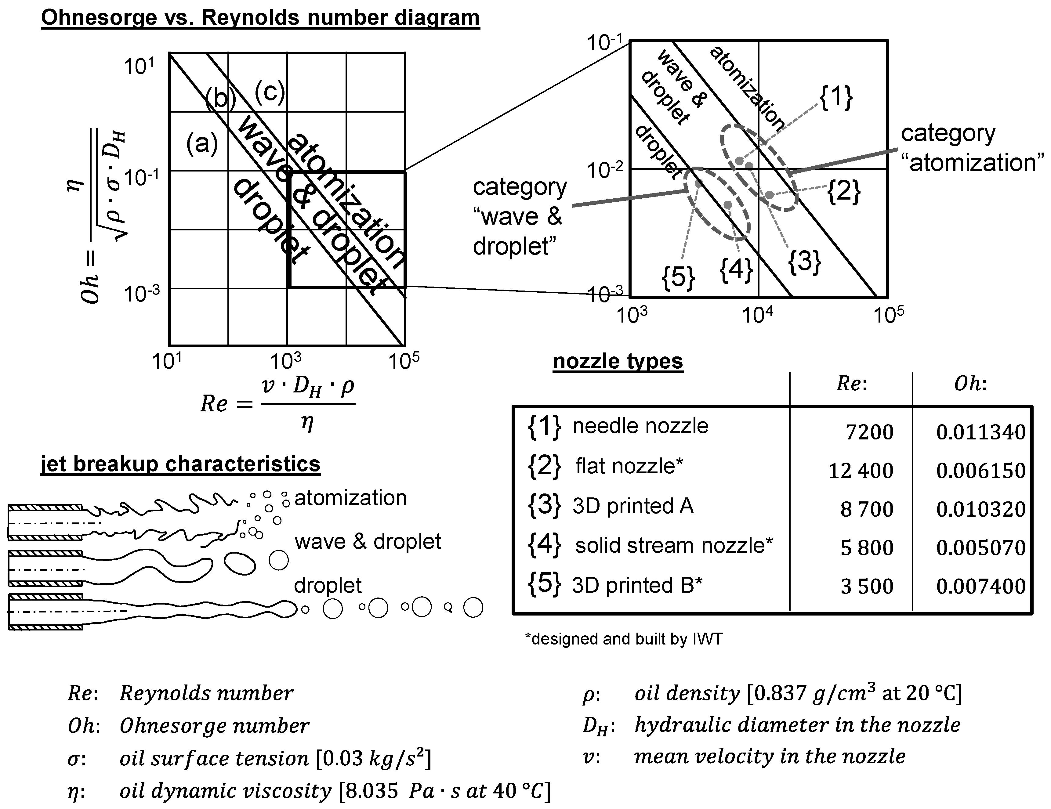
In this context, three dimensionless numbers are important to characterize a fluid jet. In particular, the jet breakup can be characterized in advance in the Ohnesorge vs. Reynolds number diagram. The jet breakup can be divided into three fields (“droplet” (a), “wave & droplet” (b), and “atomization” (c)) (Figure 1) [9,10]. Due to the high jet velocity, the fields (b)] and (c) are of importance for grinding fluid nozzles.
The Reynolds number (Re) is a dimensionless number that is used to predict the transition from laminar to turbulent flow.
The Ohnesorge number (Oh) relates the viscous forces to the inertial and surface tension forces:
Thereby, it provides information about the characterization of the fluid atomization. The lower the Ohnesorge number, the weaker the friction losses due to viscous forces. This means that most of the inserted energy converts into surface tension energy and a droplet can be formed. The higher the Ohnesorge number, the more dominant is the internal viscous dissipation and the droplet decays into smaller particles [9,10].
The Ohnesorge number can be expressed as the square root of the Weber number divided by the Reynolds number (Equation (2). The Weber number is described in terms of the inertia force, , divided by the surface tension, :
By means of the Weber number, it can be evaluated how far the real shape of a droplet differs from a spherical shape. Thereby, it is a measure for the deformation of a droplet, which increases with an increasing Weber number. Therefore, the droplet will breakup into more and more tiny droplets with an increasing Weber number [11].
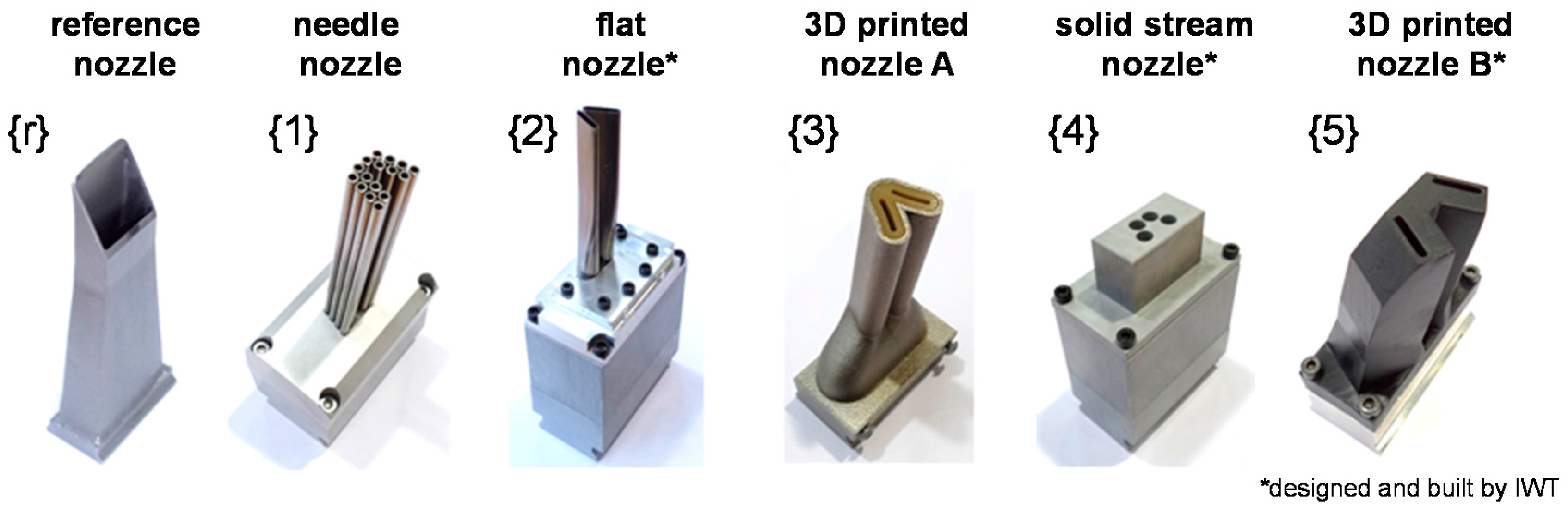
Based on this, grinding fluid nozzles {1–5} were chosen, which have an identical outlet cross-section and therefore provide the same average jet velocities (vjet = 35 m/s) at the outlet for the same flow rates (Qf = 100 l/min) (Figure 2). For comparison, the reference nozzle {r} was also investigated. This nozzle represents the current state of technology in the industrial environment. This nozzle differs from the nozzles {1–5} in the grinding fluid flowrate (Qf = 330 l/min) and in the jet velocity (vjet = 12 m/s). Due to the low jet velocity, the jet does not break up before it reaches the grinding contact zone.
To determine the positions for the nozzles {1–5} in the Ohnesorge vs. Reynolds number diagram and the characteristics of the jet breakup, the dimensionless numbers are calculated. The oil used has a surface tension of , a dynamic viscosity of , and a density of . Using the mean velocity and the hydraulic diameter in the nozzle, which are specific to each nozzle, the Ohnesorge and the Reynolds numbers are calculated. The results are shown in Figure 1.
For these settings, the nozzles can be classified into three categories. The needle nozzle {1}, the flat nozzle {2}, and the three-dimensional (3D) printed nozzle A {3}, which are close to the area “atomization” in the diagram (category “atomization”). The solid stream nozzle {4} and the 3D printed nozzle B {5} are in the area “wave & droplet”, close to the area “droplet” (category “wave & droplet”). The reference nozzle {r} generates a coherent jet with no breakup for the considered conditions (category “coherent jet”) at a rather small jet velocity far below cutting speed vc.
3.2. Characterization of Fluid Dynamic Aspects of Grinding Fluid Jets
The grinding fluid jet breakup was characterized with the help of high speed photography. A camera was used to take high resolution pictures (20.2 mega pixel) with an extremely short exposure time. The pictures were illuminated from behind the grinding fluid jet, whereby a flash illuminated a translucent glass plate with an exposure time of 1/60,000 s. The even illumination of the background is transmitted through the grinding fluid jet. The pictures with the transmitted light through the grinding fluid jet allow knowledge to be gained regarding the jet characteristics, namely the widening of the jet, the distribution of the droplets, and the jet breakup (Figure 3).
The impact pressure of the grinding fluid jet was measured using a high resolution piezoelectric sensor (measuring tip diameter: 1.0 mm). The distribution of pressure was determined by moving the sensor through the grinding fluid jet (Figure 4, bottom right). A flow-optimized cover (Figure 4, top right) redirected the jet behind the measurement area, so that no deflected fluid could influence the measurement. These measurements allow for a better understanding of the distribution and the size of the droplets inside the jet. Thus it is possible to review the category of jet breakup for the nozzles.
The sensor scanned the grinding fluid jet ten times on one line and measured the force at several measuring points. The error bars indicate the min–max values (Figure 4, bottom left) and show reproducible results. In addition to the distribution of pressure, the time sequences were analyzed and it was possible to obtain knowledge about the regularity and the height of the impact pressure of the droplet chain.
The energy efficiency of the nozzles is evaluated with the static pressure within the pipe directly in front of the nozzle. The pressure is measured with a calibrated digital pressure transmitter. The used silicon sensor has a resolution of 0.1 bar.
3.3. Grinding Process
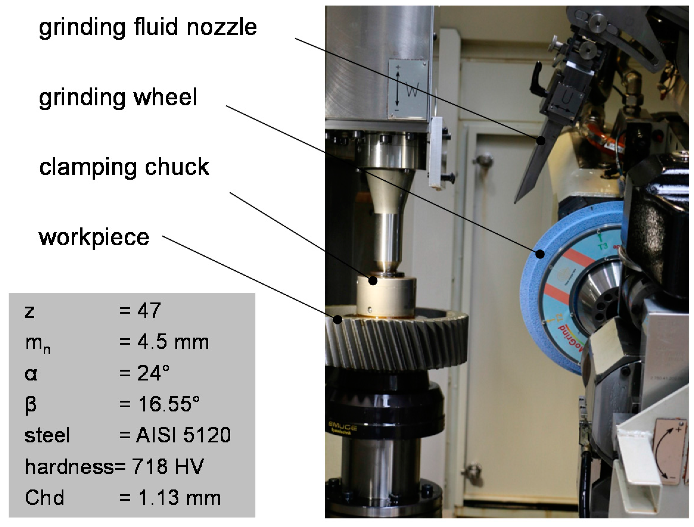
In the profile grinding experiments, pre-machined case-hardened gears were machined on a gear grinding machine (KAPP KX 500 FLEX), which enabled the machining of gears with a diameter of up to 500 mm as well as a module from m = 0.5 to 10 mm with conventional and superabrasive tools (Figure 5).
The workpieces are helical gears. These gears are characterized by 47 teeth, a normal module of mn = 4.5 mm, a bevel angle of β = −16.55°, a pressure angle of α = 24°, and a width of b = 65 mm. The material is AISI 5120 and the gears are case-hardened and blast-cleaned. The gears have a hardness of 718 HV and a case hardness depth Chd of 1.13 mm.
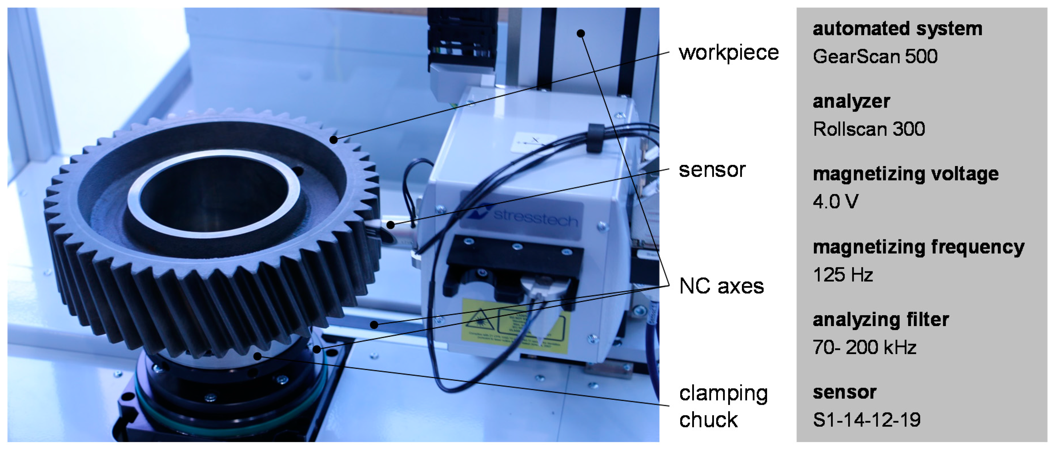
For the micromagnetic test to characterize the thermo-mechanical impact on the ground tooth flanks, the Stresstech measuring device Rollscan R 300 and the Stresstech NC unit GearScan 500 were used (Figure 6). These instruments enable a fully automatic testing of the gear. Hereby, a sensor moves by means of NC-controlled axes on previously programmed tracks along the tooth flank. Barkhausen noise was analyzed at the center of the right tooth profile. This automatic measurement allows a high reproducibility in comparison to manual tests.
4. Results and Discussion
As explained below, the fluid dynamic investigations provide a characterization of fluid jets and their breakup. Furthermore, the grinding experiments show the impact of the jet characteristics on the grinding process.
4.1. Characterization of Fluid Jets and Their Breakup
Through the use of the above-described high-speed photography, the fluid jets of the different nozzles were characterized. A standardized measurement of the length of the coherent part of the jet lcoherent before atomization makes it possible to compare the fluid jets. The results for these lengths, which are the average lengths of nine measurements of each nozzle, are shown in Figure 7.
The jets of the needle nozzle {1}, the flat nozzle {2}, and the 3D printed nozzle A {3} decay within a short length. The three values for the coherent length are similar to each other, as well as the values in the Ohnesorge vs. Reynolds number diagram are closely matched. The dark areas in the photos show many tiny droplets, which adsorb the light of the illuminated background. This observation points out that the three nozzles are comparable with regard to their position in the Ohnesorge vs. Reynolds number diagram and generate an “atomization” jet breakup. This might be due to the high turbulence directly at the nozzle outlets, which is caused by the high mean velocity inside the nozzles. The solid stream nozzle {4} and the 3D printed nozzle B {5} have inner designs with optimized flow characteristics, which significantly reduce the turbulence at the nozzle outlet. This can explain the results for the longer coherent lengths of these two nozzles. For the evaluation of the coherent lengths, only the respectively lower outlet was analysed, as defects in the 3D-printing of the upper outlet were determined for the 3D printed nozzle B {5} (these defects result in a short coherent length for the upper outlet). The results again reflect the relationship between the positions in the Re-Oh-diagram, which are comparable for both nozzles {4} and {5}, and the coherent jet lengths for this category.
Apart the jet characteristics, the nozzles influence the measured pressure in the pipe directly in front of the nozzle for a constant flow rate (Figure 7). For the needle nozzle {1} a pressure of pnozzle = 13.8 bar is measured, whereby for 3D printed nozzle B {5} a pressure of pnozzle = 5.7 bar is measured. The nozzle {2}–{4} are between these values. These pressure values correlate in inverse manner with the coherent lengths. These different power drops in the nozzles generate a corresponding turbulence flow, which correlates with the jet break up.
It can be summarized that the five nozzles {1–5} can be classified into the two categories “atomization” and “wave & droplet”, and the results for the coherent jet lengths matches with this observation. For the category “wave & droplet” greater values for the coherent length can be reached than for the category “atomization”.
Besides the optical jet characteristics, the fluid jets of the different nozzles differ significantly from each other with regard to the temporal course of the impact pressure. The impact pressure was measured for a nozzle of each category. The results of the measurement for the reference nozzle {r} (category “coherent jet”), as well as for the needle nozzle {1} (category “atomization”) and the solid stream nozzle {4} (category “wave & droplet”) are shown in Figure 8.
The reference nozzle {r} shows the lowest fluctuations in impact pressure. This is due to the low jet velocity and the coherent jet. Despite the equal and constant fluid flow rate and the jet velocity of the solid stream nozzle {4}, as well as the needle nozzle {1}, the solid stream nozzle {4} shows the most significant fluctuations in impact pressure. This can be explained by the distribution of the droplets, which is also shown in high-speed photos. The solid stream nozzle {4} generates a comparably long coherent grinding fluid jet that decays in the transitional area into relatively large droplets, which generates a greater impact pressure fluctuations than small ones. The fluid jet of the needle nozzle {1} shows an “atomization” breakup of the jet close to the nozzle outlet. The resulting small droplets are distributed evenly and therefore generate only minimal fluctuations, as well as a relatively low impact pressure.
The results show that grinding fluid nozzles not only have an impact on the widening of the jet as a function of jet velocity and flow rate, but also affect the jet breakup, the distribution of the droplets, and therefore the fluctuations in impact pressure.
4.2. Grinding Technology
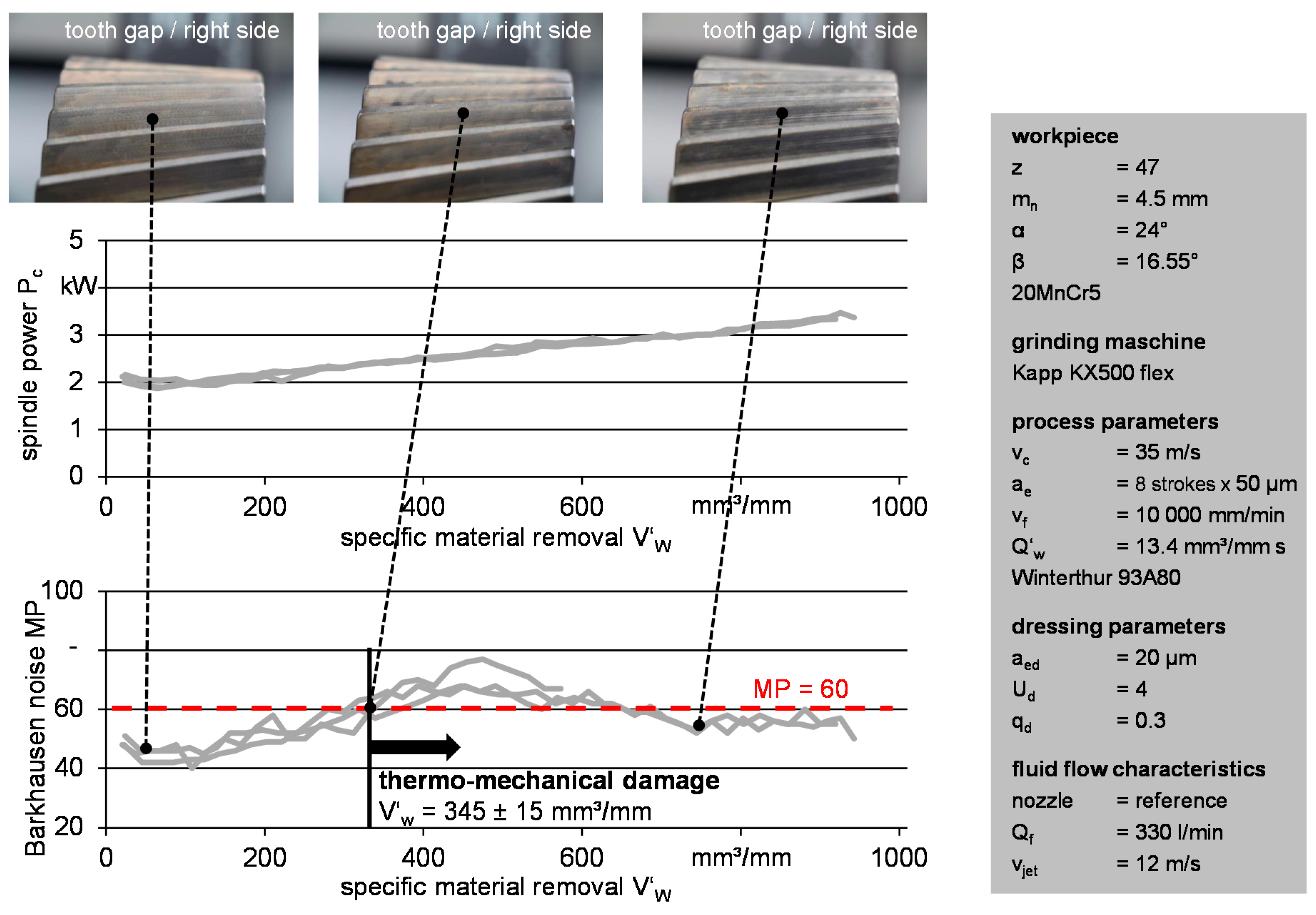
Different grinding fluid nozzles were applied that show different jet characteristics (“coherent jet”, “wave & droplet” and “atomization”). In order to compare these types of nozzles, a grinding process was developed that was tested three times with the reference nozzle {r} to determine the reproducibility. For a practical process and a fast reaching of the process limit, the gears were machined without pre-grinding in eight strokes and with a depth of cut ae of 50 µm in each case. The dressing conditions were precisely adjusted to the requirements, so that an increased thermo-mechanical load of the surface layer could be achieved after grinding only a few gear gaps. The results for this reference process are shown in Figure 9.
The courses of the spindle power in all three of the repetitions are similar to each other, and the courses of the Barkhausen noise analysis are also closely matched. Hence, the repetition trials verify the reproducibility of the process. In order to compare the grinding fluid supply conditions for the six nozzles, the limit for the thermo-mechanical damage were compared using Barkhausen noise. Therefore, the limit for the thermo-mechanical damage for the reference process was determined with nital etching. When the nital etching indicates grinding burn, the Barkhausen noise value MP exceeds 60. For the reference process, a specific removed material volume V’W of 345 ± 15 mm3/mm was removed before this limit had been reached.
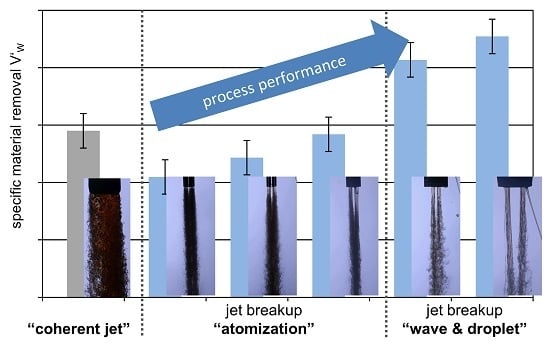
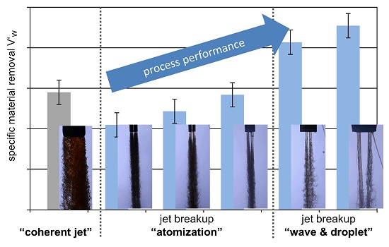
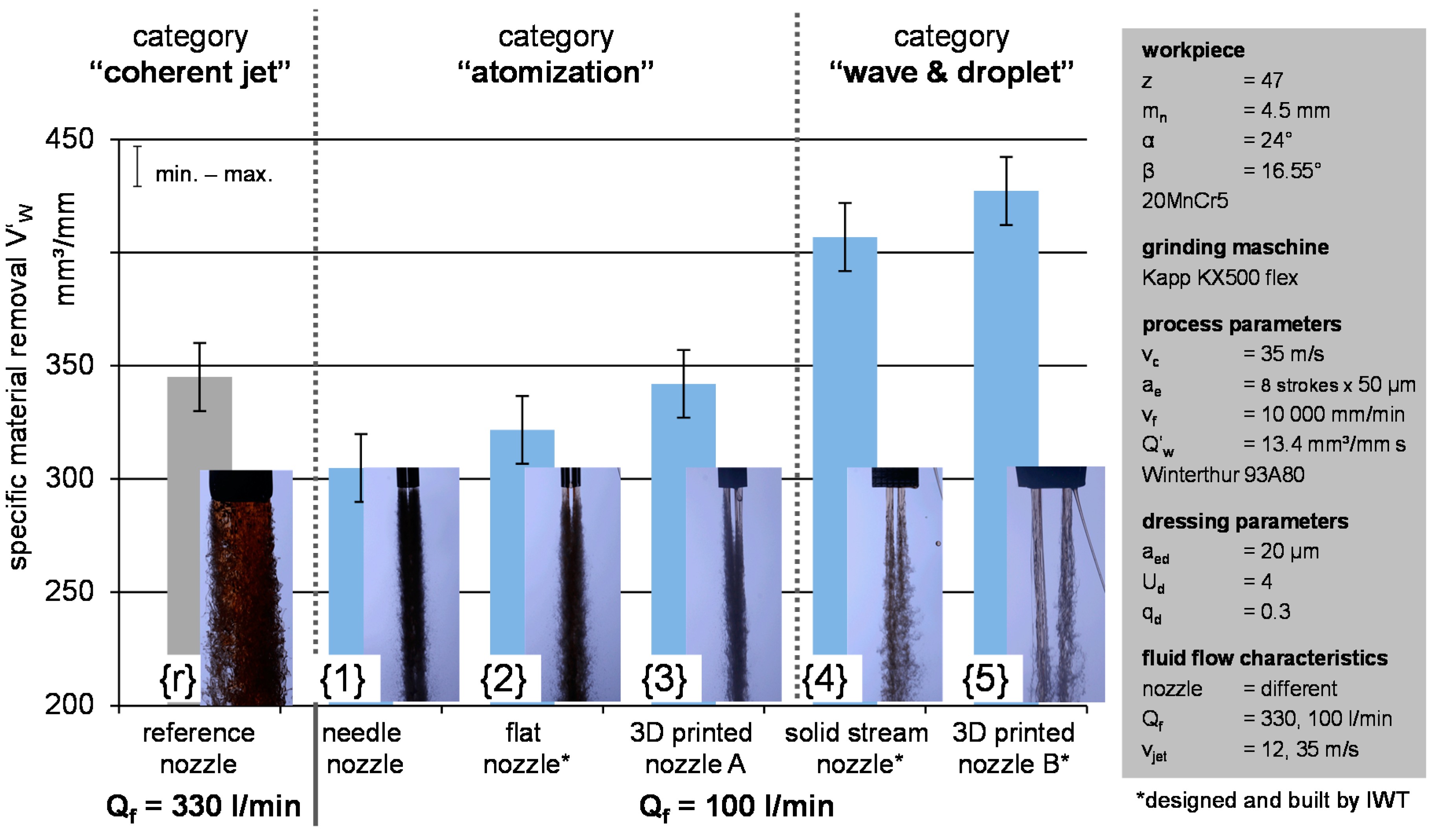
Based on the above-described grinding process, as well as the method to detect thermo-mechanical damage, all discussed nozzles were analyzed. The values for the specific removed material volume V’W, before thermo-mechanical damage occurs, for each nozzle are shown in Figure 10.
Using the reference nozzle {r}, a specific removed material volume of V’W = 345 ± 15 mm3/mm was reached. This result can be attributed to the much higher grinding fluid flowrate (Qf = 330 l/min) and the coherent jet. For the nozzles of the category “atomization” and “wave & droplet”, a significant lower grinding fluid flowrate of Qf = 100 l/min and a higher jet velocity of vjet = 35 m/s was adjusted which corresponds to the cutting speed vc. With the needle nozzle {1}, the flat nozzle {2}, and the 3D printed nozzle A {3} (category “atomization”), a specific removed material volume of V’W = 311–349 mm3/mm was achieved. The highest specific removed material volume of V’W = 415–436 mm3/mm was reached with the nozzles of the category “wave and droplet”. The results of the grinding tests correlate with the coherent lengths of the jets and the calculated positions in the Ohnesorge vs. Reynolds number diagram. A longer coherent jet leads to a higher specific removed material volume. This might be due to a better wetting of the grinding wheel for a “wave and droplet” jet breakup. In conclusion, for the optimized grinding fluid supply versus the reference fluid supply, the specific removed material volume can significantly be increased (up to 26%//436 mm3/mm {5} to 345 mm3/mm {r}) with a simultaneous decrease of the grinding fluid flow rate (reduction of 70%//100 l/min {5} to 330 l/min {r}). For a reduced grinding fluid flow rate (100 l/min), an appropriate inner design of the nozzle alone can lead to an increase in the process performance by up to 40% (436 mm3/mm {5} to 311 mm3/mm {1}).
5. Conclusions and Outlook
In the fluidic investigations conducted in this study, the grinding fluid jet and the jet breakup were characterized by means of high-speed photography. The impact pressure was analyzed using a high resolution piezoelectric senor. The grinding trials showed the impact of the jet characteristics on the grinding process.
The grinding fluid jet characteristics considered here were divided into three different categories “coherent jet”, “wave & droplet”, and “atomization”, depending on the grinding fluid nozzle. The different jet characteristics should already be taken into account when designing a grinding fluid nozzle. The jet characteristics and breakup have a significant influence on how much of the workpiece volume can be removed before thermo-mechanical damage occurs. With a higher jet quality, namely a breakup that is more “wave & droplet” than “atomization”, a higher specific removed material volume can be achieved by up to 40%.
Further investigations using high-speed photography are planned to consider the interaction between the grinding fluid jet and the rotating grinding wheel for different types of jet breakup. This should deliver a better knowledge of the interaction and the efficient disposal of grinding fluid on the wheel and within the contact zone leading to a better grinding performance. In addition, the previous knowledge should be transferred to other grinding processes with higher grinding wheel circumferential speeds and complex contact conditions.
Acknowledgments
The IGF-research project 18204/N of the FVA—Forschungsvereinigung Antriebstechnik e.V.—was part of the program Industrielle Gemeinschaftsforschung und—entwicklung (IGF) and was supported by the German Federal Ministry for Economics and Technology (BMWi) via the Industrial Cooperative Research Associations (AiF). The authors express their sincere thanks to the collaborating industrial partners for the support of this research.
Author Contributions
Philip Geilert and André Wagner conceived and designed the experiments; Philip Geilert performed the experiments and analyzed the data; André Wagner and Carsten Heinzel contributed to the analysis and the interpretation of results.
Conflicts of Interest
The authors declare no conflict of interest.
References
- Brinksmeier, E.; Heinzel, C.; Meyer, L. Coolant supply conditions and their effect on the workpiece surface layer in grinding. Prod. Eng. Res. Dev. Ann. WGP 2001, 8, 9–12. [Google Scholar]
- Webster, J.A.; Cui, C.; Mindek, R.B., Jr. Grinding fluid application system design. CIRP Ann. 1995, 44, 333–338. [Google Scholar] [CrossRef]
- Rowe, W. 8-Application of Fluids. In Principles of Modern Grinding Technology, 2nd ed.; William Andrew Publishing: Boston, MA, USA, 2014. [Google Scholar]
- Kirsch, B. The impact of contact zone flow rate and bulk cooling on the cooling efficiency in grinding applying different nozzle designs and grinding wheel textures. CIRP J. Manuf. Sci. Technol. 2017, 18, 179–187. [Google Scholar] [CrossRef]
- Webster, J.; Brinksmeier, E.; Heinzel, C.; Wittmann, M.; Thöns, K. Assessment of grinding fluid effectiveness in continuous-dress creep feed grinding. CIRP Ann. 2002, 51, 235–240. [Google Scholar] [CrossRef]
- Wittmann, M.; Heinzel, C.; Brinksmeier, E. Evaluating the efficiency of coolant supply systems in grinding. Prod. Eng. Res. Dev. Ann. WGP 2004, 11, 39–42. [Google Scholar]
- Meyer, L.; Heinzel, C.; Brinksmeier, E. Analysis and optimization of coolant supply conditions in grinding. Prod. Eng. Res. Dev. Ann. WGP 2005, 12, 27–30. [Google Scholar]
- Cui, C. Experimental Investigation of Thermofluids in the Grinding Zone. Ph.D. Thesis, University of Connecticut, Fairfield, CT, USA, 1995. [Google Scholar]
- Li, D. Encyclopedia of Microfluidics and Nanofluidics; Springer: New York, NY, USA, 2008. [Google Scholar]
- Ohnesorge, W.V. Die bildung von tropfen an düsen und die auflösung flüssiger strahlen. J. Appl. Math. Mech. 1936, 16, 355–358. [Google Scholar] [CrossRef]
- Oertel, H. Prandtl—Führer Durch die Strömungslehre—Grundlagen und Phänomene, 13th ed.; Springer Vieweg: Karlsruhe, Germany, 2012. [Google Scholar]
Figure 1.
Ohnesorge vs. Reynolds number diagram and jet breakup characteristics (after [10]).
Figure 1.
Ohnesorge vs. Reynolds number diagram and jet breakup characteristics (after [10]).

Figure 2.
Different concepts of fluid supply nozzles.

Figure 3.
Measurement setup for high-speed photography.
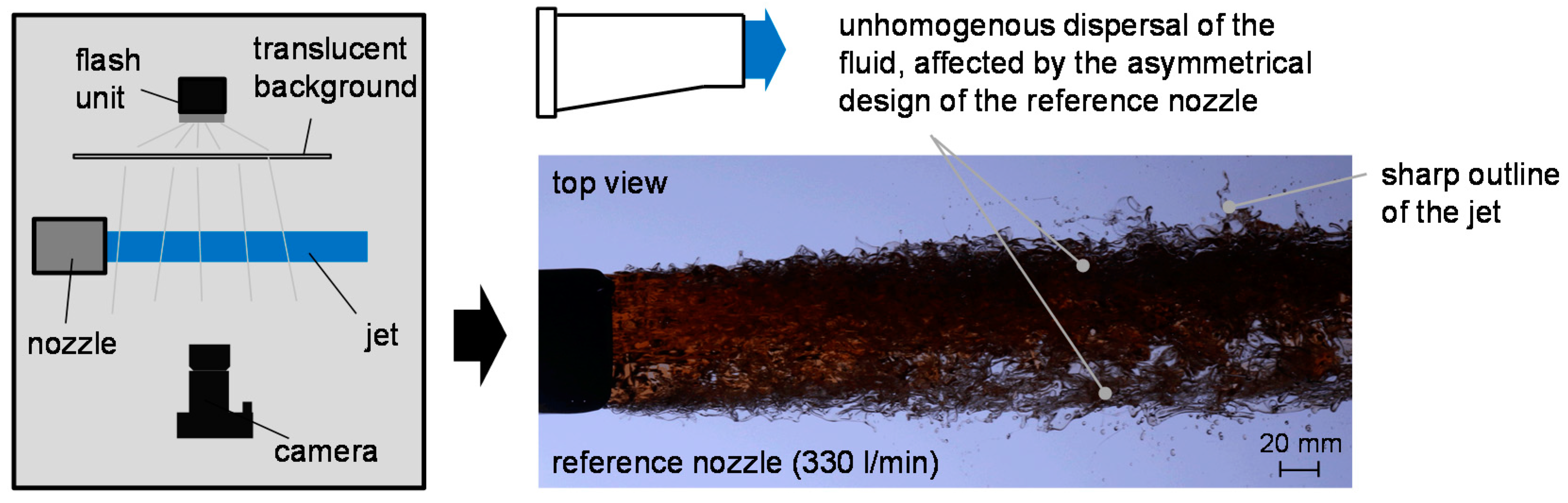
Figure 4.
Experimental setup, scanning program and repeatability for impact pressure measurement.
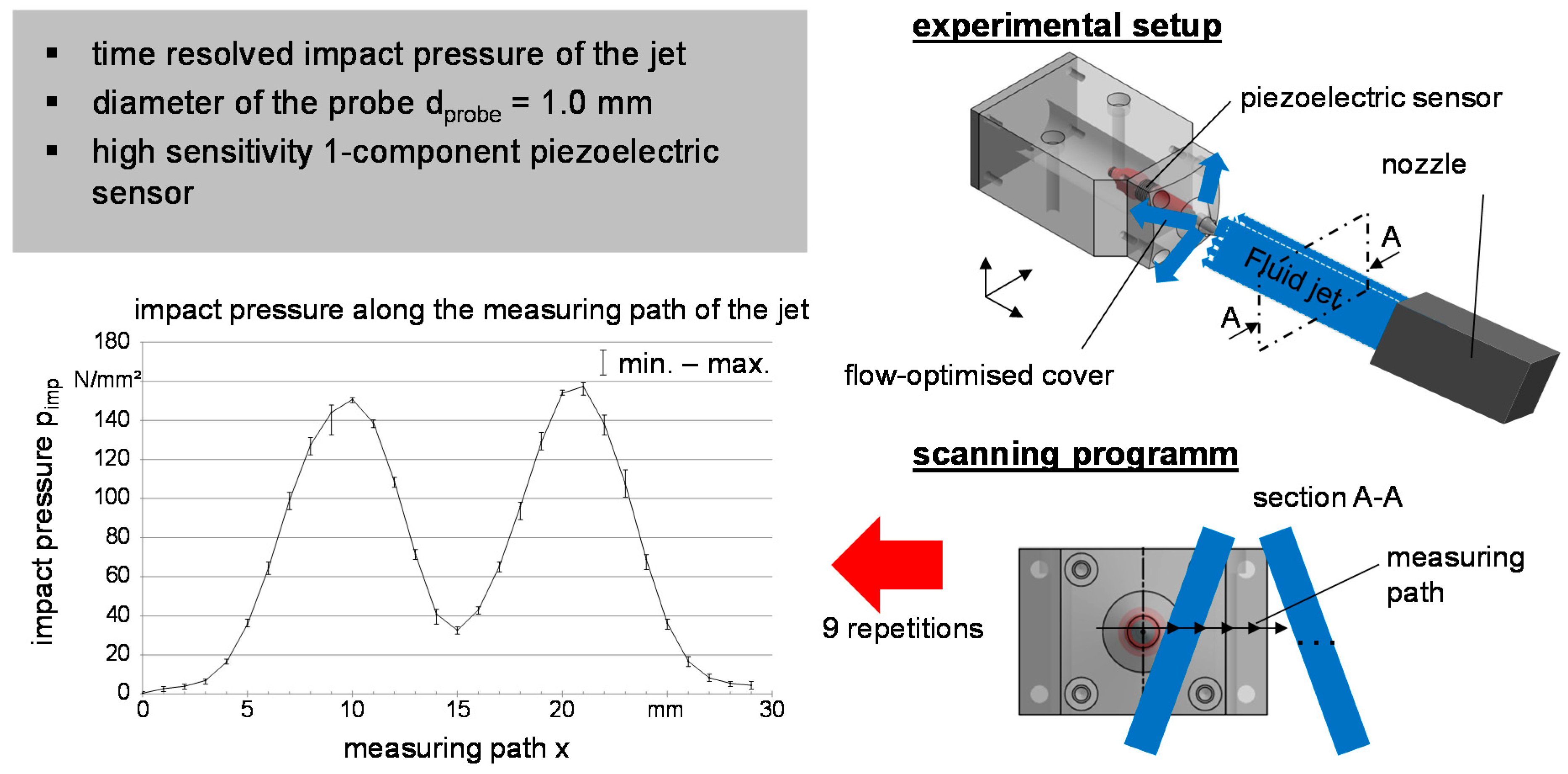
Figure 5.
Experimental setup for grinding tests.

Figure 6.
GearScan 500 in use and measurement parameters.

Figure 7.
Characterization of fluid supply nozzles—coherent jet lengths.
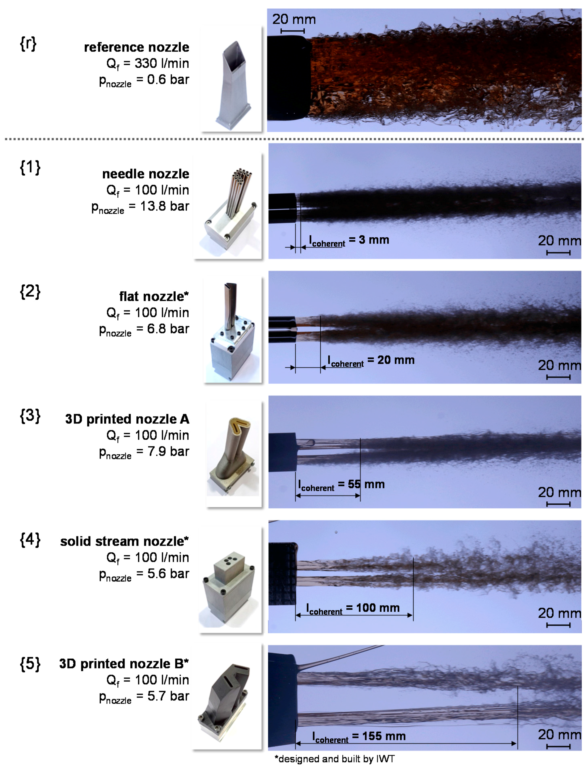
Figure 8.
Characterization of the fluctuations in impact pressure for different jet breakups.
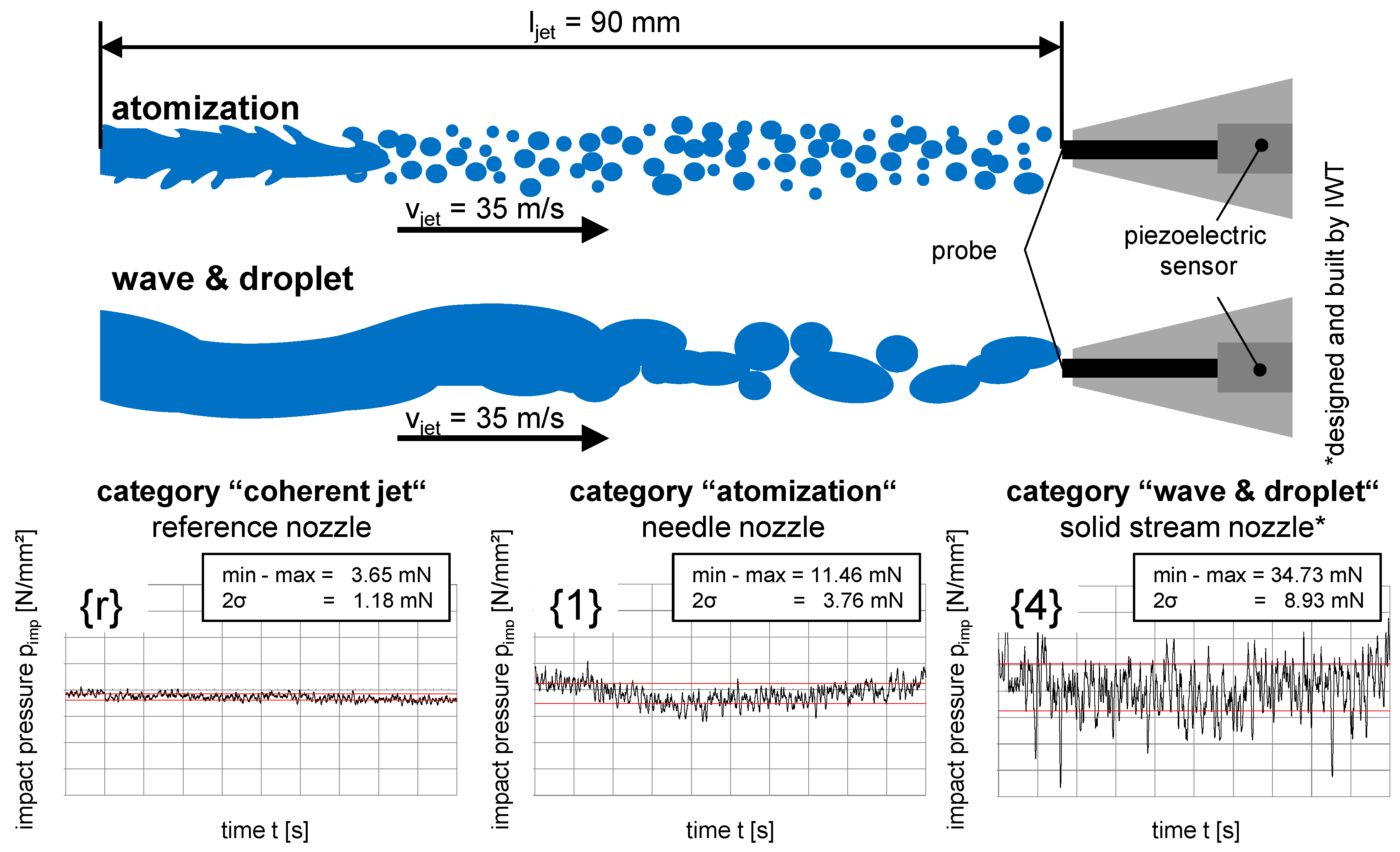
Figure 9.
Barkhausen noise and spindle power for the reference gear grinding process.

Figure 10.
Grinding tests—Influence of the jet breakup.

© 2017 by the authors. Licensee MDPI, Basel, Switzerland. This article is an open access article distributed under the terms and conditions of the Creative Commons Attribution (CC BY) license (http://creativecommons.org/licenses/by/4.0/).
Share and Cite
MDPI and ACS Style
Geilert, P.; Heinzel, C.; Wagner, A. Grinding Fluid Jet Characteristics and Their Effect on a Gear Profile Grinding Process. Inventions 2017, 2, 27. https://doi.org/10.3390/inventions2040027
AMA Style
Geilert P, Heinzel C, Wagner A. Grinding Fluid Jet Characteristics and Their Effect on a Gear Profile Grinding Process. Inventions. 2017; 2(4):27. https://doi.org/10.3390/inventions2040027
Chicago/Turabian StyleGeilert, Philip, Carsten Heinzel, and André Wagner. 2017. "Grinding Fluid Jet Characteristics and Their Effect on a Gear Profile Grinding Process" Inventions 2, no. 4: 27. https://doi.org/10.3390/inventions2040027