
Request-Centric Wireless Bus Information Management System


1
Department of Environmental Control Technology, Greenhouse Systems Technology Center, Industrial Technology Research Institute (ITRI) Central Region Campus, Nantou 540, Taiwan
2
Department of Electrical Engineering, Graduate Institute of Communication Engineering, National Chung Hsing University, Taichung 402, Taiwan
*
Author to whom correspondence should be addressed.
Inventions 2016, 1(4), 23; https://doi.org/10.3390/inventions1040023
Submission received: 14 September 2016
/
Revised: 31 October 2016
/
Accepted: 31 October 2016
/
Published: 9 November 2016
(This article belongs to the Special Issue New Inventions in Vehicular Guidance and Control)
Abstract
:This invention relates to a wireless bus information management system, which includes bus stop and vehicle management subsystems. The management signals are transmittable between bus stops and the vehicle. Based on vehicle management signals, the bus stop management subsystem can obtain information about the bus route identification, the number of unoccupied seats, the intention to stop or not, etc. Similarly, with the bus stop management signals, the vehicle management subsystem can make the decision of stopping. Accordingly, when a passenger wants to get off the vehicle or there are unoccupied seats, the vehicle management subsystem will inform the bus stop management subsystem such that the passengers waiting at the bus stop may flexibly schedule their travel plan. The proposed distributed wireless system is detailed by a prototype implementation and a simulation analysis, which is shown to be feasible and scalable.

1. Introduction
1.1. Background and Motivation
In order to improve the service quality and operational efficiency of a bus management system, many system models have been proposed. However, most of the conventional systems apply a centralized control to handle the passenger demands with respect to the control behaviors of a bus and a bus stop. Moreover, no explicit interactions between the passengers waiting at a bus stop and a coming bus are considered. In contrast, this paper proposes a distributed bus information system, integrating passenger requests and management information exchange between a bus and a bus stop.
Based on the bus management signals, the bus stop management subsystem can obtain the information about the bus route identification, the number of unoccupied seats, intention to stop or not, etc. Through bi-direction communication, the bus management subsystem can determine whether the bus stop management signals should be processed. As depicted in Figure 1, on the basis of the signal system, control system and communication system, a pair of a bus stop and a bus can work as a group to dynamically perform request analysis and service control. Therefore, passengers on the bus or waiting at the bus stop can obtain sufficient information to flexibly schedule their travel plan.
This work aims to develop a request-centric bus information system by considering two phases: (1) request analysis; and (2) service control. The first phase is to build up a signal system, a control system, and a communication system for information exchange and analyzing the demands of passengers on a bus or waiting at a bus stop. The second phase is to handle the corresponding service and provide sufficient information for passengers to organize their travel plan. The major contributions and key features of this work are: (1) Proposing a novel distributed interactive system for bus stops and buses; (2) Developing an information management scheme for improving the system efficiency and supporting an adaptive service with respect to the demands of passengers.
The rest of the paper is organized as follows: Section 1.2 reviews bus systems, wireless technologies, and service platforms. Section 2 depicts the proposed information management system, which is derived from our invention patent [1]. Compared with the conceptual description from [1], this work develops the communication protocols, details the major system components, illustrates the system prototype, and provides basic service analysis. Section 3 shows the system implementation and describes the service analysis. Finally, we summarize the study in Section 4.
1.2. Literature Review
This section summarizes the most relevant existing research on three categories: bus systems, wireless technologies, and service platforms.
Relating to the design of bus systems, the authors in [2] propose “The Flexible Bus System” (FBS), which reduces the wait time and the ride time of the passengers by using the information provided by the passengers about their source and the destination. The proposed FBS replaces the scheduled bus lines in a way that buses can dynamically change their routes according to passenger’s demands. Informing the passengers about the accurate bus locations makes this system much more efficient and information rich as compared to traditional systems. However, the control attributed is centralized and there is no interaction between a bus and the passengers on the bus.
The authors in [3] propose a hierarchical bus rapid transit (BRT) system to extend the conventional BRT system based on multi-tier wireless sensor networks (WSNs), which helps to map the good features of WSN to BRT systems and provides solutions for BRT technologies. However, the real-time performance and the interactions between bus stops and the bus are not considered. In [4], an intelligent wireless bus-station system dedicated to disabled, wheelchair and blind passengers is introduced. The system design is presented at the different levels: hardware, micro-kernel and protocol, which has been implemented on the experiment bus in France.
Relating to wireless technologies, in [5,6], approaches are presented to integrate Radio Frequency Identification technology (RFID) in a wireless network, which is used to extend the read range of an RFID system and further optimize the performance of a RFID reader. Thus, a bus tracking application is built to monitor bus traffic and can inform administrators of the status of the bus. In order to avoid the current driver-based manual operation in the public traffic system, the authors in [7] propose a supervisory system based on General Packet Radio Services (GPRS) and ZigBee technologies to improve the operation efficiency of bus monitoring system and realize an intelligent transportation system.
Since intelligent transportation systems based on WSN have been applied to solve the traffic problems in recent years, the authors in [8] further extend the research results, introduce an intelligent transportation system based on RFID and WSN, and then discuss the hardware and software design principles of the system. The experimental results show that the system is characterized by low cost and high reliability.
Relating to service platforms, smartphone-based services for driver and passengers [9] are developed to effectively collect information from the surrounding environment such that the road transport can be smarter and safer. The authors in [10] explore the application feasibility and key technologies to build a vehicle network, including the design of vehicle terminals, vehicle positioning, system functions and system communications. The authors in [11] examine the request of passengers, drivers and management centers. Based on the study, the system framework includes three correlative request layers: intelligent service, intelligent management and intelligent control. However, system implementation and performance analysis are not provided.
2. Materials and Methods
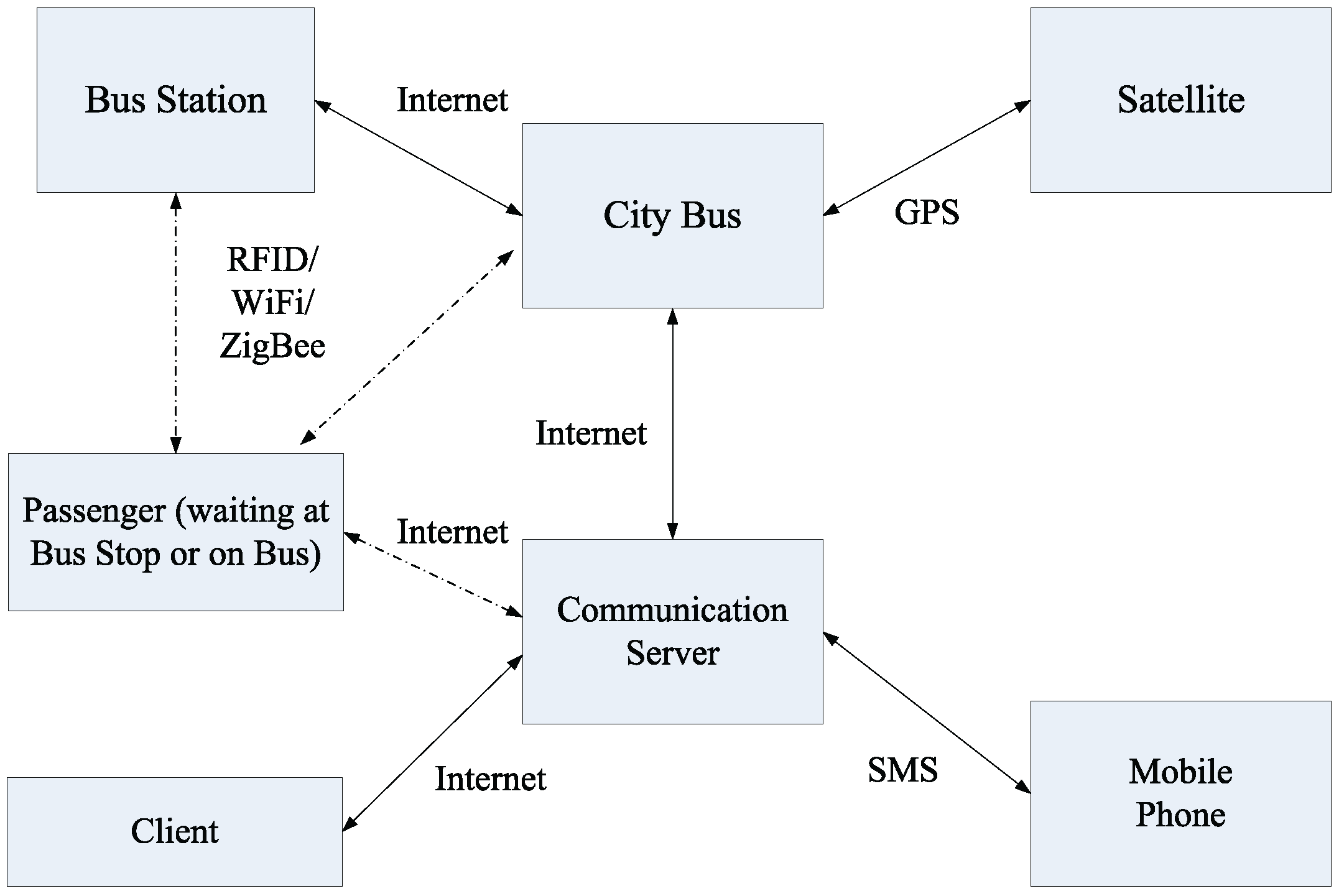
As a conceptual modern transportation system, a multi-subject system (such as human–machine–environment engineering, system and control engineering, etc.) applies information technology, data transmission technology, electronic control technology, computer technology and sensor technology to construct a human-vehicle-road-environment integrated system [11]. Accordingly, Figure 2 shows a typical architecture of a bus information system, integrating the information among passengers, a bus, and a bus stop. The following subsections describe the mechanism of information flow and data management of the proposed bus system, which consists of embarking/disembarking requests and service management.
2.1. Information Flow and Service Management
Figure 3 illustrates a typical scenario for the bus identification and monitoring system. The wireless modules (e.g., GPS, WiFi, ZigBee or GPRS), responsible for data communication, are equipped on the moving bus. As soon as a bus enters the communication range of the bus stop, information exchange may start via WiFi/ZigBee. Afterwards, the data obtained on the bus is sent to the communication server and the bus stop via Internet/GPRS, and vice versa. If a bus on a different route passes the bus stop, the proposed system will ignore it. Thus, once the communication channel is built, the stored data in the database, including the location of the bus and the time of arrival, can be retrieved by the user interface and updated accordingly. The procedures of the data transfer are described in steps 1–7 (Figure 4):
- Passengers input the desired route/destination information to the bus stop via RFID/ WiFi/ZigBee.
- The bus stop sends the requested information to the bus.
- Passengers on the bus input stop requests or transfer information to the bus.
- The decision of stopping at the bus stop is made by the bus based on the stop request and seats available on this bus. If there are no stop requests and no seats available, the bus sends the Non-Stop passing signal to the bus stop. However, if the bus is requested to stop at the current bus stop, the bus sends the stopping signal to the bus stop.
- The bus stop sends the updated transfer information to the passengers waiting at the bus stop.
- The bus stop sends the updated transfer information to the bus.
- The bus sends the updated transfer information to the bus and the passengers on the bus.
2.2. Message Format
For expressing control information, the data frame contains six types of messages: TxID, RxID, , , , and that are responsible for the sender ID, the receiver ID, the number of boarding requests at the bus stop, the number of available seats on the bus, the number of passengers on the bus, the boarding capacity on the current bus stop, and the number of stop requests on the bus, respectively. With the maximum carrying capacity of each bus , Table 1 shows a typical example of the data frame during the communication process between a bus and a bus station. Note that the underlined numbers are obtained via bi-directional communication between a bus and a bus stop.
2.3. Design of Interactive Bus Stops
This section presents the design principles of interactive bus stops. The communication procedures are described as follows:
- Passengers use Near-Field Communication (NFC) technology or RFID technology to perform a boarding request.
- The bus stop collects the information of the intention of passengers.
- As the buses enter the communication range of the bus stop, the bus stop periodically broadcasts the passenger information and the route status of the buses.
- The receiver of the bus receives the station’s message and the route/arrival information of other bus lines.
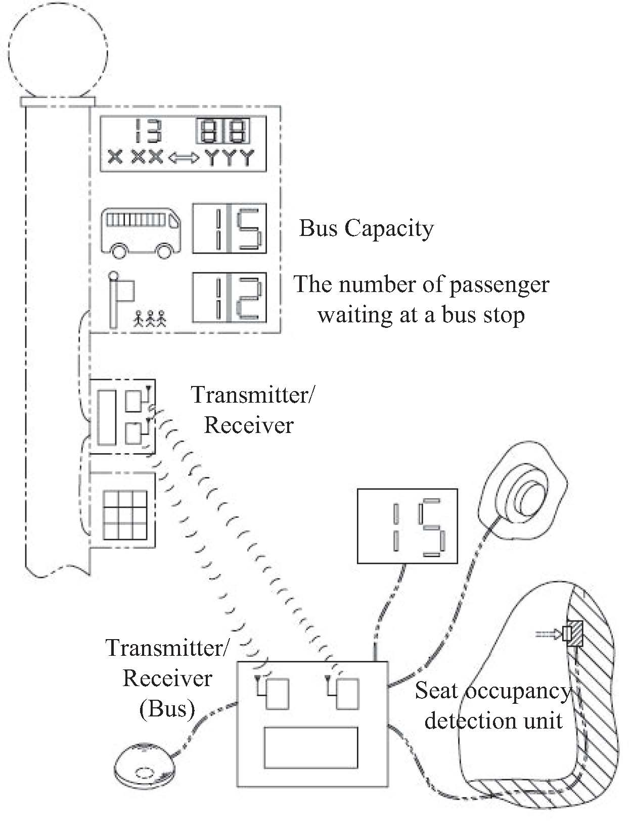
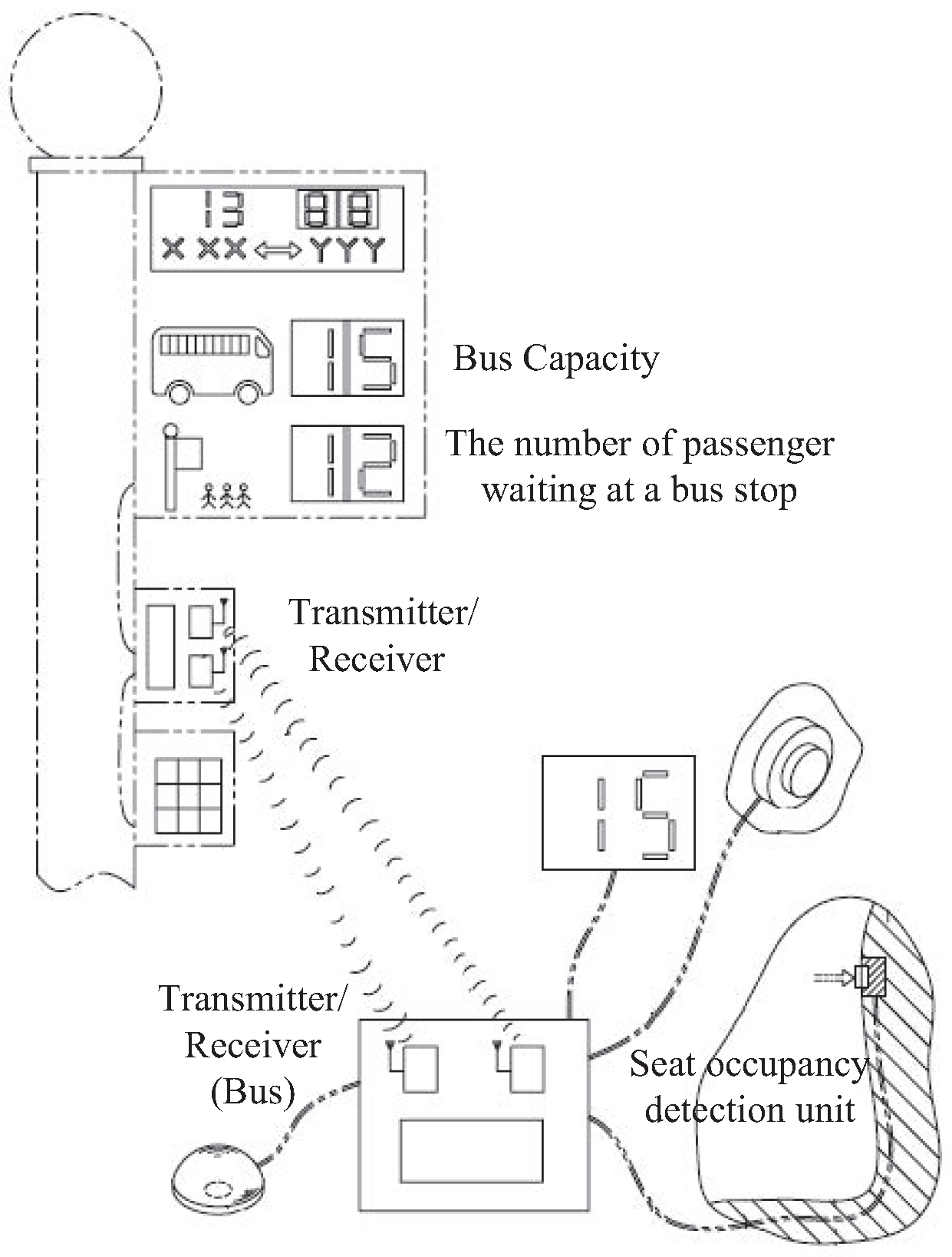
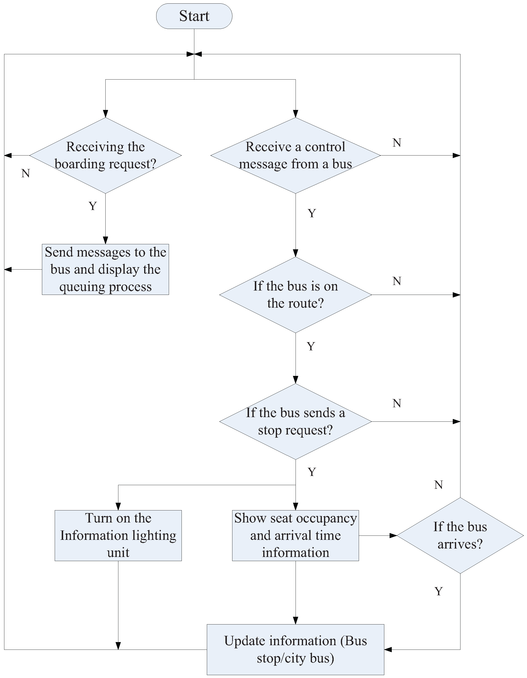
Figure 5 shows the major components of an interactive bus stop, including (1) a transmitter/receiver of a bus stop; (2) information processing unit; (3) information display unit; (4) informative lighting unit; (5) power unit; and (6) the boarding request reader (RFID/NFC). As shown in Figure 5, this bus stop provides an information display to remind passengers to check the estimated arrival time and capacity of the targeted bus. In order to have a conceptual framework for the bus stop implementation, Figure 6 depicts a prototype of an interactive bus stop, which can perform information exchange with a bus and illustrate the updated information for the passengers waiting at the bus stop. Moreover, the bus stop may send the boarding request to a bus and provide a real-time notification on bus capacity. The detailed procedures of an interactive bus stop are shown in Figure 7, where the bus stop executes a request analysis to check the boarding request at the bus stop and the control message from the bus.
2.4. Real-Time Passenger Information System
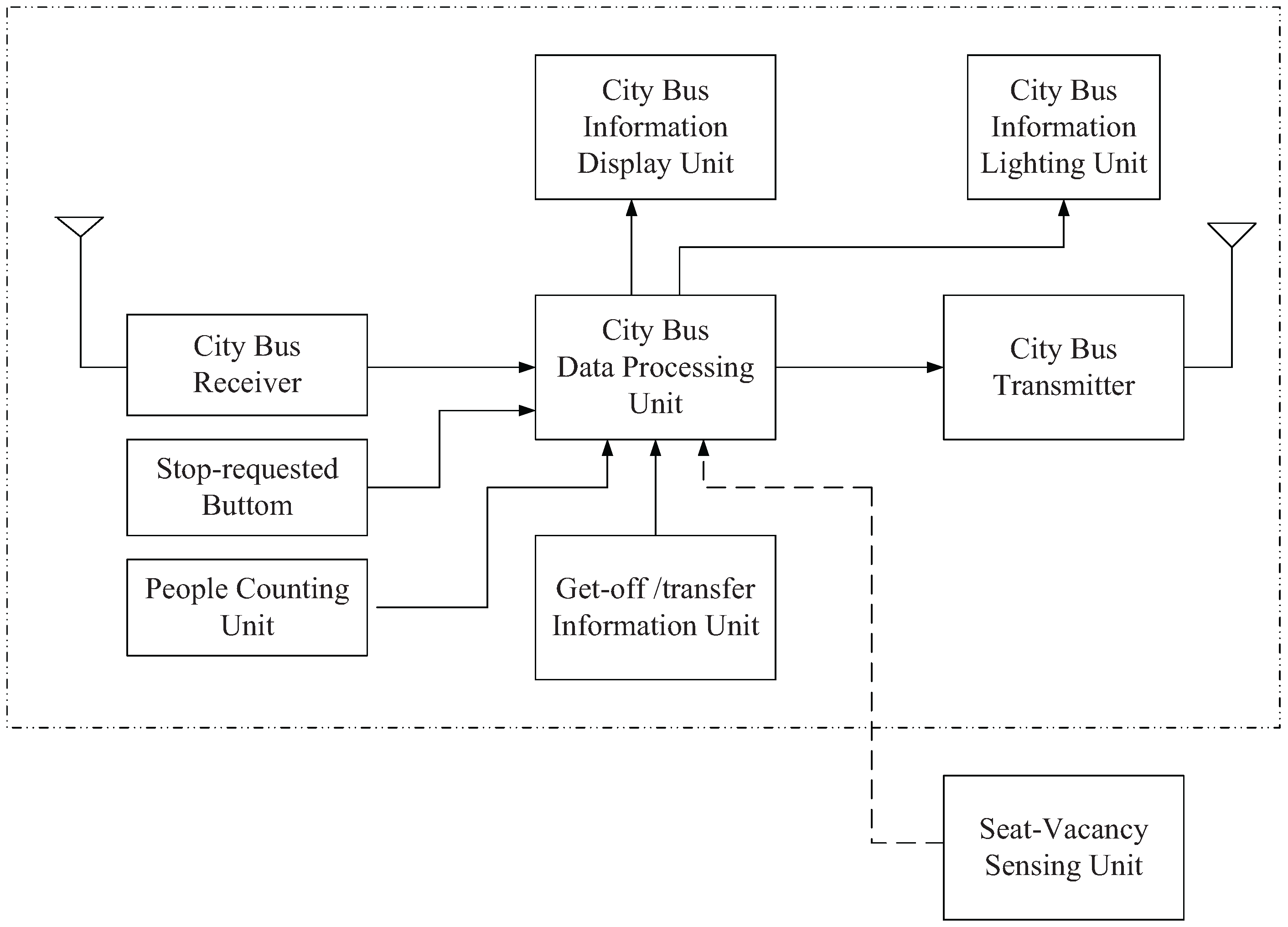
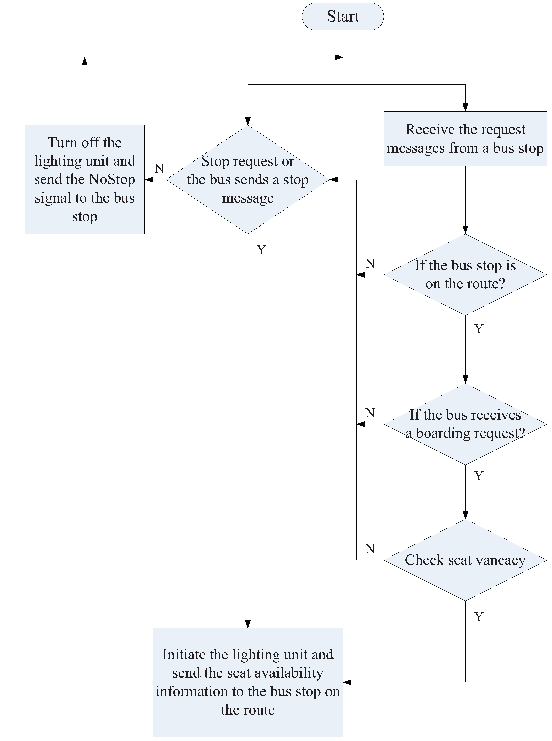
Referring to the communication protocol as described in Figure 4, the bus sends the on-board people counting information to the bus stop and provides the route/arrival information to the passengers on board. Figure 8 shows the major components of a real-time passenger information system, including (1) bus transmitter/receiver; (2) information processing unit; (3) information display unit; (4) informative lighting unit; (5) people counting unit; (6) the Stop Request button; and (7) seat occupancy detection unit. Figure 9 (left) and Figure 9 (right) illustrate the conceptual design of a seat occupancy detection unit and a people counting unit, respectively. Observe that, similar to the operations of a bus stop, the bus performs request analysis and service management to build a real-time passenger information system. Figure 10 demonstrates a high-level flowchart, which shows major steps and how information is used in the system. During the communication process, the bus first checks and processes the stop request sent from a bus stop or the passengers on the bus. If the request is initiated, then the bus turns on the lighting unit and sends the bus capacity information to the bus stop on the route.
3. Results
To assess the feasibility of the proposed system, this section details software/headware implementation and performance analysis.
3.1. Software Implementation
While receiving the boarding requests, the bus stop will transmit a message about the number of waiting passengers. Afterwards, as receiving the signal from a bus, the bus stop will further update the bus information in the display unit. An example of software design is summarized in Table 2.
Similarly, when receiving the stopping request from a bus stop, the bus will examine the bus capacity and may trigger the lighting unit to remind the bus driver to take corresponding actions. Moreover, during the embarking period, the people counting unit records the number of boarding passengers and then forwards this information to the bus stop for updating the number of waiting passengers. Table 3 details the design principle of bus information management.
3.2. Hardware Implementation
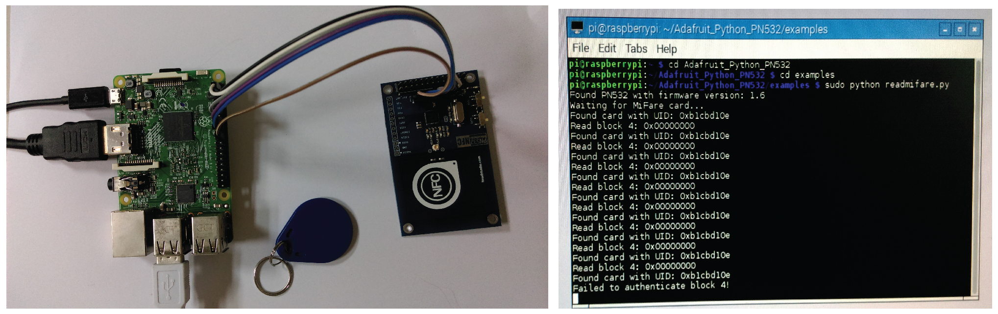
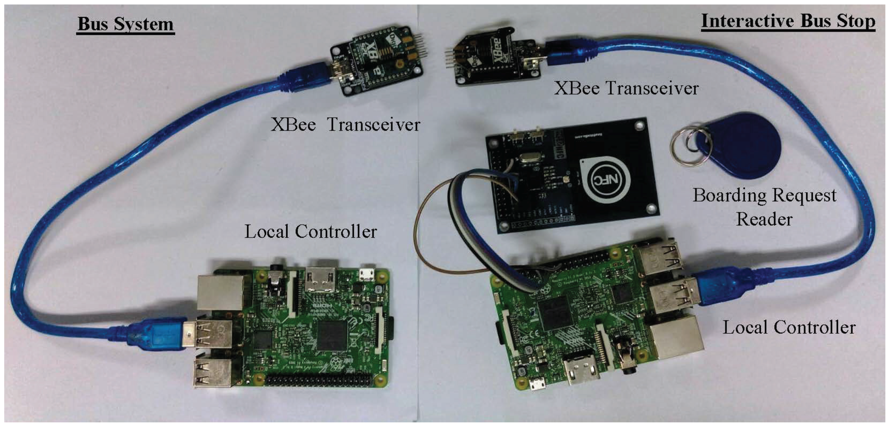
This subsection illustrates possible hardware implementations for four major components: (1) stop-requested unit of a bus stop; (2) bus stop/bus communication module; (3) seat-vacancy sensing unit; and (4) people counting unit. Figure 11 depicts an example of a stop-requested unit at a bus stop, which is responsible for analyzing the intentions of boarding the bus. The proposed system applies a wireless sensor network to build a communication channel between a bus and a bus stop, integrating an Arduino Fio V3 platform (SparkFun Electronics, Niwot, CO, USA) with an XBee wireless transmission module (Digi International, Minnetonka, MN, USA) (Figure 12). The specifications of a XBee S2C are detailed in Table 4. Accordingly, Figure 13 (left) and Figure 13 (right) show a bus system (consisting of an XBee transceiver and a local controller) and an interactive bus stop (consisting of a XBee transceiver, a boarding request reader and a local controller), respectively, which illustrates a typical prototype of the proposed system.
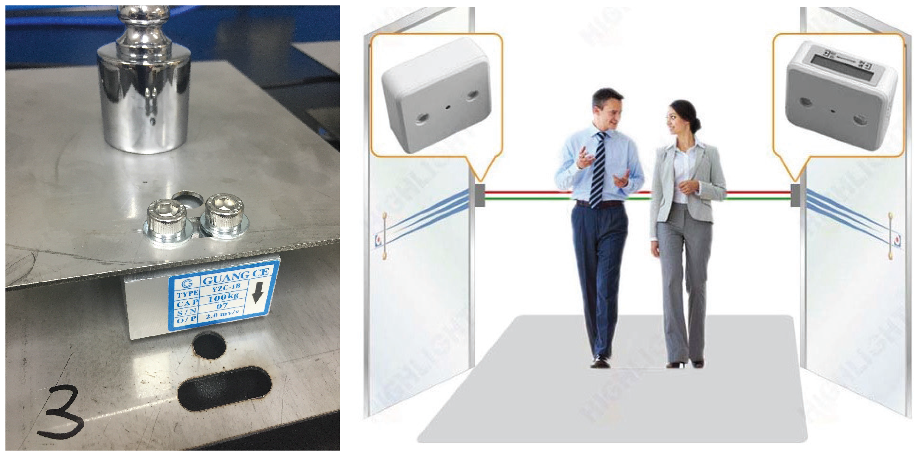
In order to detect seat occupancy, each seat on a bus may be equipped with a load cell. Figure 14 (left) shows a detection scenario. With a load cell of 100 Kg, if the weight reading is larger than a predefined threshold, then the seat is claimed as occupied. On the other hand, Passive Infrared (PIR) sensors may be applied to perform people counting in the entrance area of a bus, which provides information about the number of standing passengers in a bus (Figure 14 (right)). Therefore, with load cells and PIR sensors, the current bus capacity is obtained. For instance, considering a bus with 21 seats and standing space for 30 (including the bus driver), a people counting product (e.g., an HPC005 from Highlight (Hong Kong, China)) can be used to calculate the number of the disembarking passengers to get off of the bus and the number of the embarking passengers getting on the bus. Therefore, if the difference between the number of disembarking passengers and the number of embarking passengers in the previous bus stop is 26 (e.g., , ), then we have , including the bus driver. Afterwards, with the seat occupancy information of load cells, say 15 seats occupied, the bus may send a message about the maximum boarding capacity to the coming bus stop (i.e., the available number of embarking passengers is 25). Based on this message, the waiting passengers may flexibly adjust their travel plans.
3.3. Service Analysis
This subsection performs a service analysis of a transport system by applying the public conveyance model (PCM) [12] for a bus-route system. In the PCM, assume that the hopping probability H to the bus stop depends on the number of waiting passengers. Accordingly, if the waiting passengers increase, the hopping probability to the bus stop decreases. However, in [12], the number of passengers who get off of the bus is ignored. In the general bus system, the embarking and disembarking processes have taken place in parallel and the time taken by the waiting passengers to get into the bus is always adequate for the disembarking passengers to get off of the bus, which means that the hopping probability H for a real bus would also depend on the number of passengers who get off at the bus stop [13]. Therefore, the hopping probability of a bus H is given by
where
is the maximum carrying capacity of each bus, and the hopping probability of a bus is Q when there are no waiting passengers. Note that the expression of (1) is motivated by the common expectation that the time needed for the passengers to board a bus is proportional to their number.
Now, let us estimate the time taken by a bus to move from bus stop i to bus stop , which yields
Following the setting in [13], which assumes that among m bus stops of a bus route, passengers evenly get off at every bus stop, the number of disembarking passengers and remaining passengers at the i-th bus stop are
with .
In [13], the number of waiting passengers is assumed to be larger than the boarding capacity (i.e., ), which may not be a typical case for a bus stop. In contrast, this work assumes that the number of waiting passengers is less than the boarding capacity, which yields
where is the maximum carrying capacity of each bus. Thus, the average time for a bus to move from a bus stop to the next bus stop of the route is
In the simulation analysis, the settings of the main system parameters are , , , and . As depicted in Figure 15, if the waiting passengers increase, the hopping probability to the bus stop decreases, which leads to a larger waiting time. For instance, consider the bus stop ID 5 with the number of waiting passengers and , the waiting time ; for the bus stop ID 15 with the number of waiting passengers and , the waiting time . Observe that referring to the analytical estimation of the average weighting time in consideration of the main system parameters, there exists a reasonably good agreement between analysis and numerical calculations.
4. Discussion
Although the proposed system may achieve effective information management, further experimental and theoretical extensions are possible. In our future work, we plan to involve more efficient mechanisms and mathematical models, which may help in demonstrating the dynamical patterns and estimating the efficiency, and traffic volume to optimize the system operation. Moreover, on the basis of the proposed network architecture, buses can be equipped with external sensing devices to monitor specific physical parameters (e.g., pollution, humidity, temperature). Therefore, with a bus network, value-added services (e.g., environmental diagnostic and management) may be provided to support and improve data collection and distribution.
5. Conclusions
This paper presents a bus information management system, which considers the interactions among a bus, a bus stop, and passengers. The core system components include two subsystems: (1) intelligent bus information management part and (2) interactive bus stop part. Based on the vehicle management signals, the bus stop management subsystem can obtain the information about the bus route identification, unoccupied seats, intent to stop or not, etc. According to the bus stop management signals, the vehicle management subsystem can determine whether the signals should be processed. Similarly, when a passenger wants to get off of the vehicle or there are unoccupied seats, the vehicle management subsystem will inform the bus stop management subsystem. The control service is detailed via software architecture design and hardware prototype implementation. In order to evaluate the effectiveness of the proposed information-based control system, a modified public conveyance model is derived for passenger transport systems, considering the number of waiting passengers and the maximum number of passengers that can get into one bus at a bus stop.
Author Contributions
Ying-Chih Chen and Chih-Yu Wen conceived and designed the systems; Ying-Chih Chen and Ping-Yen Chen implemented the system prototype; Ying-Chih Chen analyzed the data; and Ying-Chih Chen and Chih-Yu Wen wrote the paper.
Conflicts of Interest
The authors declare no conflict of interest.
References
- Chen, Y.-C.; Wen, C.-Y. Wireless Communication-Based Transport Information System. Taiwan Patent Invention No. I375895, 1 November 2012. [Google Scholar]
- Iqbal, R.; Ghani, M.U. Intelligent Bus Stops in the Flexible Bus Systems. J. Eng. Sci. Technol. Rev. 2014, 7, 59–65. [Google Scholar]
- Huang, W.L.; Tang, S.; Li, Z.; Zhu, F.; Ai, Y. A Hierarchical Bus Rapid Transit System Based on Wireless Sensor Networks. In Proceedings of the 11th International IEEE Conference on Intelligent Transportation Systems, Beijing, China, 12–15 October 2008.
- Zhou, H.-Y.; de Sousa, G.; Chanet, J.-P.; Hou, K.-M.; Li, J.-J.; de Vaulx, C.; Kara, M. An Intelligent Wireless Bus-Station System Dedicated to Disabled, Wheelchair and Blind Passengers. In Proceedings of the 2006 IET International Conference on Wireless, Mobile and Multimedia Networks, Hangzhou, China, 6–9 November 2006.
- Hatem, B.A.; Habib, H. Bus Management System Using RFID In WSN. In Proceedings of the European and Mediterranean Conference on Information Systems 2010 (EMCIS2010), Abu Dhabi, United Arab Emirates, 12–13 April 2009.
- Hannan, M.A.; Nustapha, A.M.; Hussain, A.; Basri, H. Intelligent Bus Monitoring and Management System. In Proceedings of the World Congress on Engineering and Computer Science (WCECS 2012), San Francisco, CA, USA, 24–26 October 2012.
- Feng, H.-E.; Li, L.; Yin, H.; Huang, X. Bus Monitoring System Based On ZigBee And GPRS. In Proceedings of the 2012 International Conference on Computer Distributed Control and Intelligent Enviromental Monitoring, Zhangjiajie, China, 5–6 March 2012; pp. 178–181.
- Guo, L.J.; Fang, W.; Wang, G.; Zheng, L. Intelligent Traffic Management System Base on WSN and RFID. In Proceedings of the 2010 International Conference on Computer and Communication Technologies in Agriculture Engineering (CCTAE), Chengdu, China, 12–13 June 2010; pp. 227–230.
- Campolo, C.; Lera, A.; Molinaro, A.; Paratore, S.Y.; Ruggeri, G. SMaRTCaR: An Integrated Smartphone-based Platform to Support Traffic Management Applications. In Proceedings of the First International Workshop on Vehicular Traffic Management for Smart Cities (VTM), Dublin, Ireland, 20 November 2012.
- Cai, C.-Q.; Zhang, Z.; Ji, S.-D. The Intelligent Bus Scheduling Based on ZIGBEE. In Proceedings of the International Conference on Computer Science & Education (ICCSE 2012), Melbourne, Australia, 14–17 July 2012.
- Hu, J.; Li, G. Design of City-Bus Intelligent Control System Framework. In Proceedings of the 2006 IEEE International Conference on Mechatronics and Automation, Luoyang, China, 25–28 June 2006; pp. 2307–2311.
- Tomoeda, A. Cellular Automaton Modeling of Passenger Transport Systems. In Infrastructure Design, Signalling and Security in Railway; Perpinya, X., Ed.; INTECH: Vienna, Austria, 2012; pp. 256–274. [Google Scholar]
- Tomoeda, A.; Nishinari, K. Simulations and Analytical Calculations of Elevator System factored in the Clustering of Vehicles. In Proceedings of the SICE Annual Conference, The University Electro-Communications, Chofu, Japan, 20–22 August 2008.
Figure 1.
Intelligent bus system model: the direction of information flow is represented by arrows.
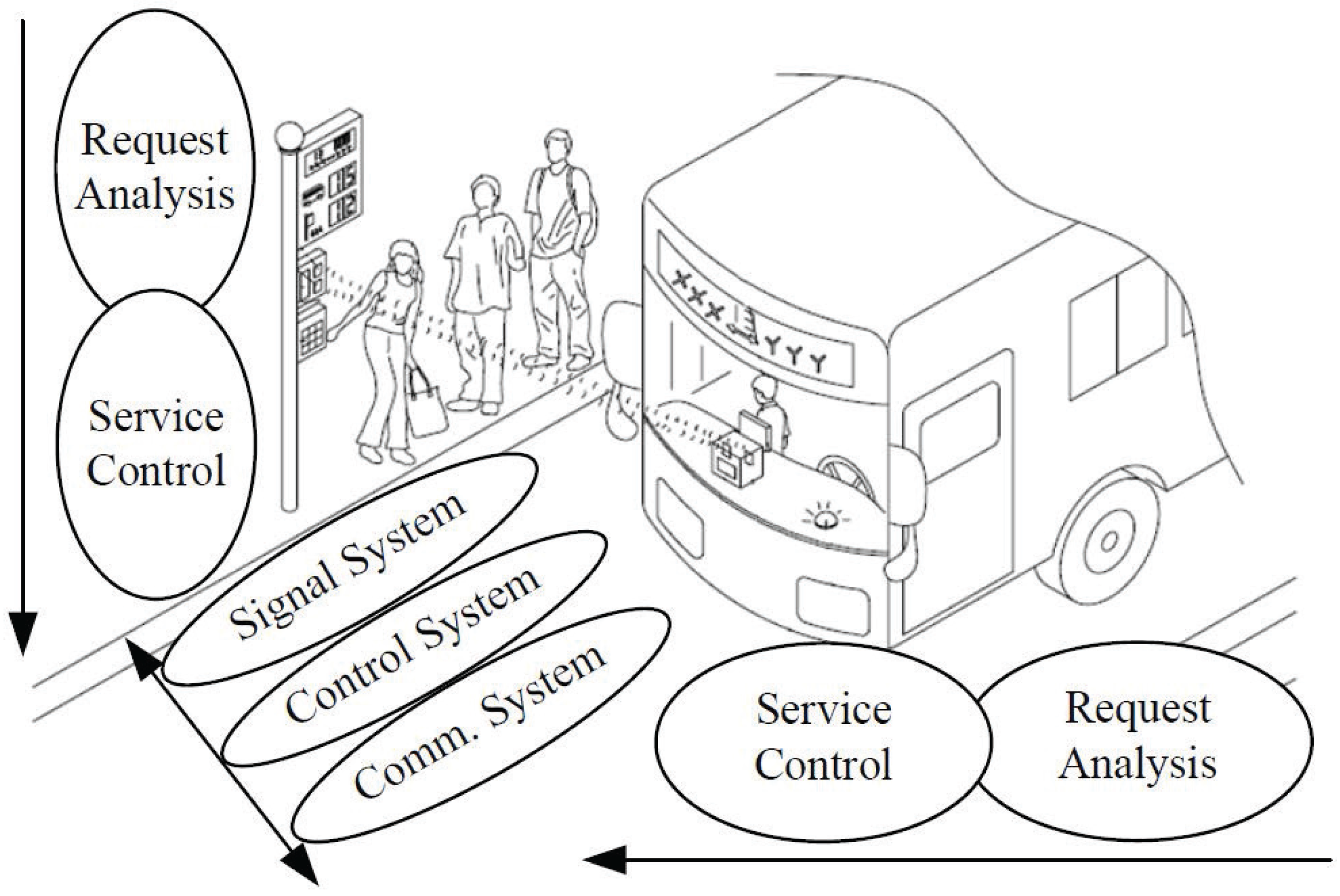
Figure 2.
Architecture of the bus information system: the dashed lines represent the communication links related to passengers; the solid lines indicate the communication links between the vehicle and the interface.
Figure 2.
Architecture of the bus information system: the dashed lines represent the communication links related to passengers; the solid lines indicate the communication links between the vehicle and the interface.

Figure 3.
A typical scenario of the bus system. Note that j is the bus stop index.
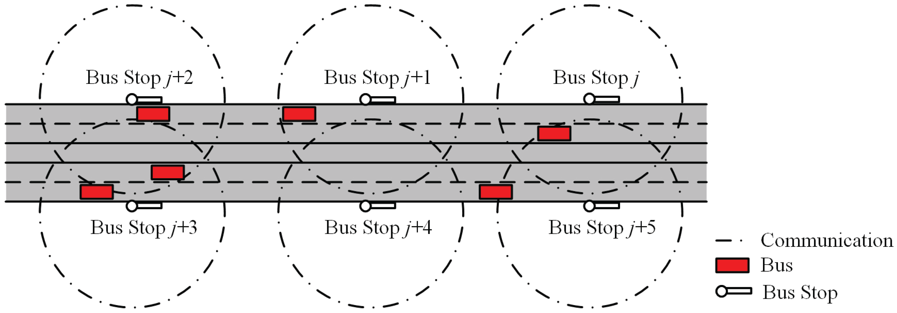
Figure 4.
Data transfer sequence of the intelligent bus system model.
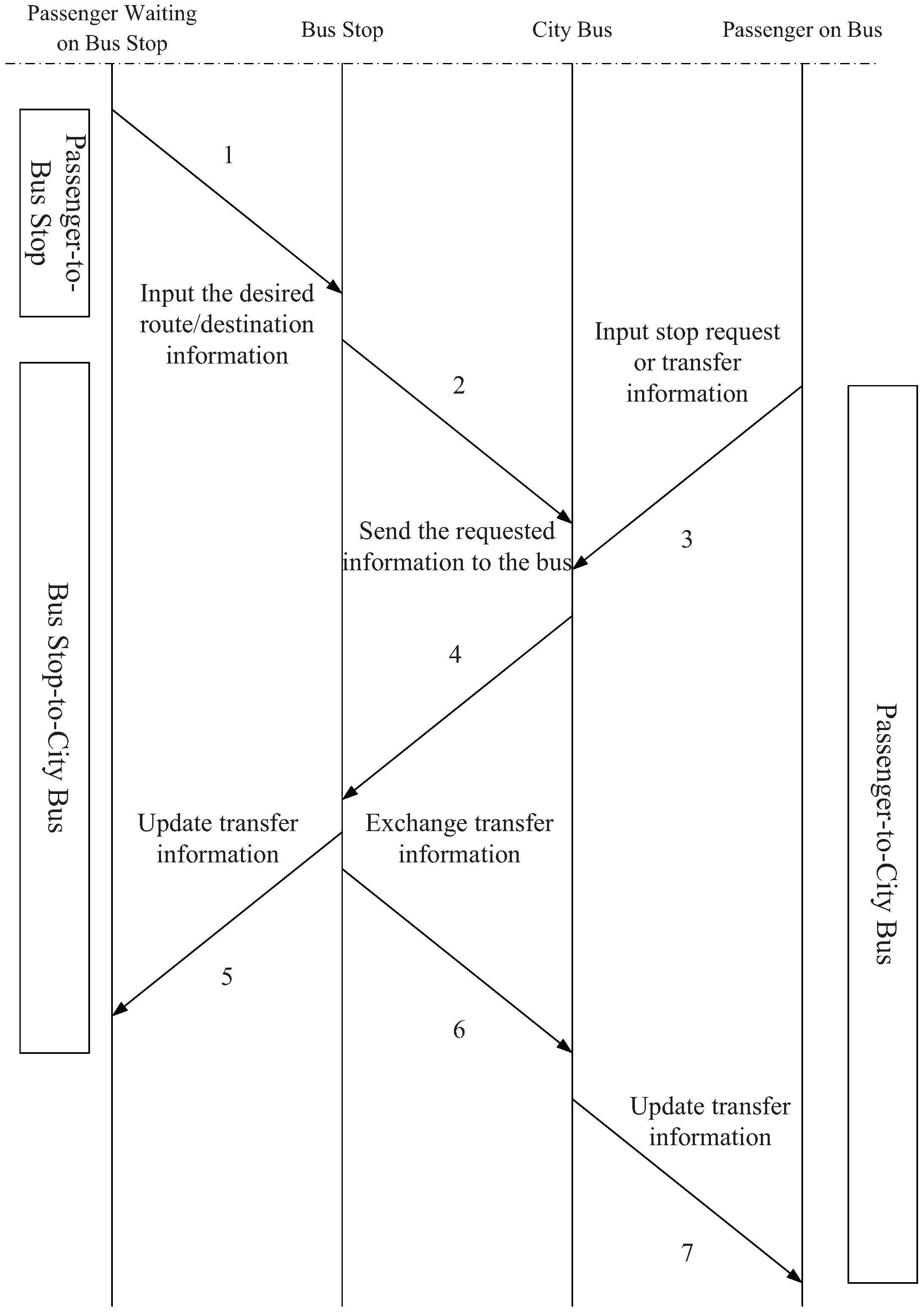
Figure 5.
The major components of an interactive bus stop. Notice that a triangle pointing down represents an antenna.
Figure 5.
The major components of an interactive bus stop. Notice that a triangle pointing down represents an antenna.
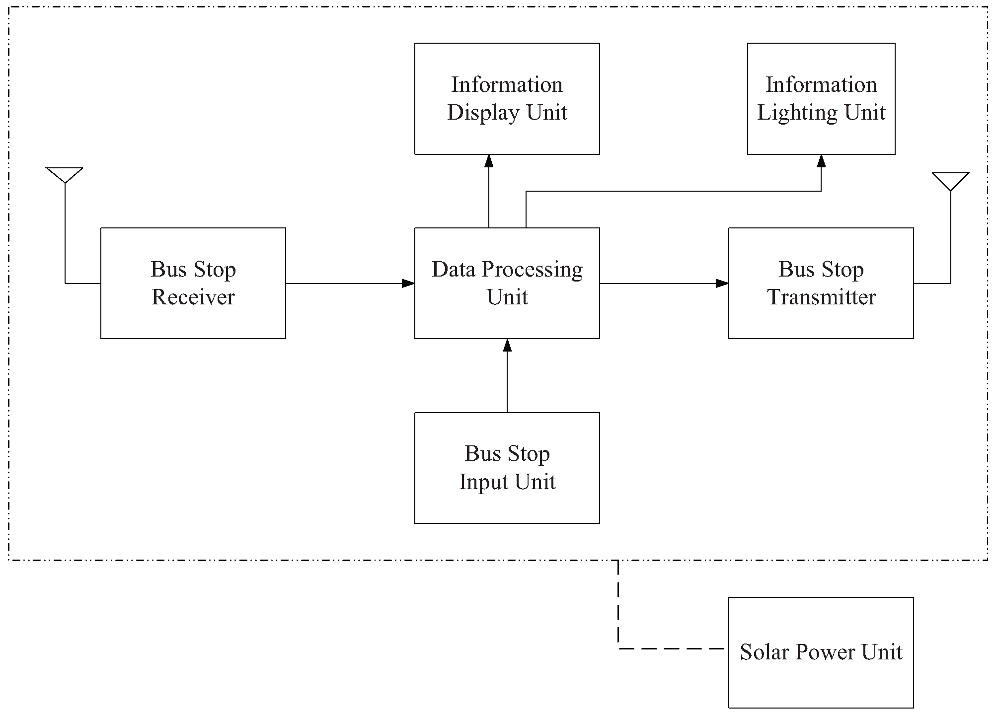
Figure 6.
A prototype of an interactive bus stop: the seat occupancy detection unit consists of sensors and load cells.
Figure 6.
A prototype of an interactive bus stop: the seat occupancy detection unit consists of sensors and load cells.

Figure 7.
Information flow of interactive bus stops: “N” represents “No”; “Y” represents “Yes”.

Figure 8.
The major components of a real-time passenger information system. Notice that a triangle pointing down represents an antenna.
Figure 8.
The major components of a real-time passenger information system. Notice that a triangle pointing down represents an antenna.

Figure 9.
Seat occupancy detection unit (left); people counting unit (right). The number 15 represents the bus capacity.
Figure 9.
Seat occupancy detection unit (left); people counting unit (right). The number 15 represents the bus capacity.
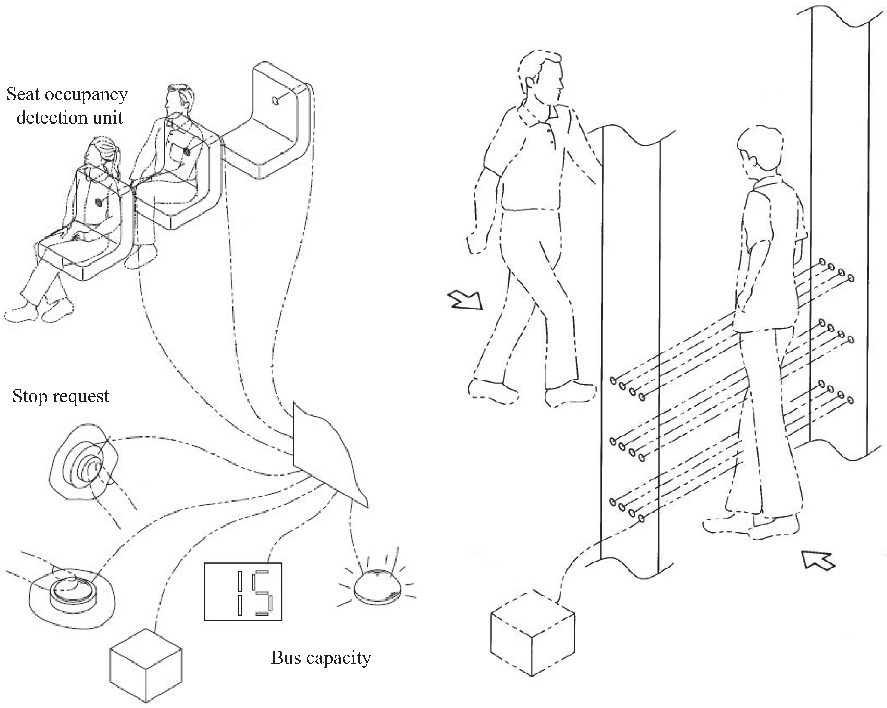
Figure 10.
Information flow of a real-time passenger information system: “N” represents “No”; “Y” represents “Yes”.
Figure 10.
Information flow of a real-time passenger information system: “N” represents “No”; “Y” represents “Yes”.

Figure 11.
The stop-requested unit of a bus stop: an example of a stop-requested unit at a bus stop (left), which is responsible for analyzing the intentions of boarding the bus (right).
Figure 11.
The stop-requested unit of a bus stop: an example of a stop-requested unit at a bus stop (left), which is responsible for analyzing the intentions of boarding the bus (right).

Figure 12.
XBee (Digi International, Minnetonka, MN, USA) wireless transmission module.

Figure 13.
A prototype of wireless bus management system: a bus system (consisting of an XBee transceiver and a local controller) (left) and an interactive bus stop (consisting of a XBee transceiver, a boarding request reader and a local controller) (right).
Figure 13.
A prototype of wireless bus management system: a bus system (consisting of an XBee transceiver and a local controller) (left) and an interactive bus stop (consisting of a XBee transceiver, a boarding request reader and a local controller) (right).

Figure 14.
Load cell (left); people counter (right).

Figure 15.
A typical run of the waiting time with bus stop IDs: Q = 0.8 with time unit; with time unit; and Q = 1.0 with time unit. Note that is the bus stop ID 5 with the number of waiting passengers.
Figure 15.
A typical run of the waiting time with bus stop IDs: Q = 0.8 with time unit; with time unit; and Q = 1.0 with time unit. Note that is the bus stop ID 5 with the number of waiting passengers.


| Bus (B) | TxID | RxID | |||||
| 1 | 30 | 1 | |||||
| Bus Stop (BS) | TxID | RxID | |||||
| 5 | 9 |
Note that the underlined bold numbers are obtained via bi-directional communication between a bus and a bus stop.
| 1. Let StopIDs be the set of bus stop IDs. |
| 2. StopIDs |
| while () |
| j is an ID number of bus stop from the bus broadcasting, where StopIDs. |
| if () |
| Update , and (referring to Section 2.2). |
| end |
| Broadcast the ID number i to bus. |
| end |
| 1. Let BusIDs be the set of bus IDs. |
| 2. Let StopIDsi be the set of bus stop IDs of the route of bus i. |
| 3. Let RStopID be a bus stop ID of the boarding requests (default value is 0). |
| 4. Let StopLedOni be an LED status of bus i. |
| (default value is false that means the LED is turned off.) |
| 5. Let GateOpeni be a gate status of bus i. |
| (default value is false, which means the bus gate is closed.) |
| 6. Denote as the distance measurement between bus i and bus stop j. |
| (, which means bus i arrives at the bus stop j). |
| 7. BusIDs |
| while () |
| j is an ID number of bus stop from the broadcasting of bus stop j ( StopIDs). |
| if ( StopIDsi == true) |
| if ( and (j - RStopID == 1 or j == min(StopIDsi))) |
| StopLedOni = true. |
| RStopID = j. |
| end |
| end |
| if (StopLedOni == true and and GateOpeni == true) |
| StopLedOni = flase. |
| elseif ( and GeteOpeni == false) |
| Update , and . |
| Broadcast a update message to bus stop j (referring to Section 2.2). |
| end |
| end |
| Specifications | XBee S2C 802.15.4 |
|---|---|
| Transceiver Chipset | Silicon Labs EM357 SoC |
| Outdoor/RF Line-Of-Sight Range | 1200 m |
| Transmit Power | +5 dBm |
| Receiver Sensitivity | −100 dBm |
| Protocol | XBee 802.15.4 |
© 2016 by the authors; licensee MDPI, Basel, Switzerland. This article is an open access article distributed under the terms and conditions of the Creative Commons Attribution (CC-BY) license (http://creativecommons.org/licenses/by/4.0/).
Share and Cite
MDPI and ACS Style
Chen, Y.-C.; Chen, P.-Y.; Wen, C.-Y. Request-Centric Wireless Bus Information Management System. Inventions 2016, 1, 23. https://doi.org/10.3390/inventions1040023
AMA Style
Chen Y-C, Chen P-Y, Wen C-Y. Request-Centric Wireless Bus Information Management System. Inventions. 2016; 1(4):23. https://doi.org/10.3390/inventions1040023
Chicago/Turabian StyleChen, Ying-Chih, Ping-Yen Chen, and Chih-Yu Wen. 2016. "Request-Centric Wireless Bus Information Management System" Inventions 1, no. 4: 23. https://doi.org/10.3390/inventions1040023