Design of a Thorium Metal Target for 225Ac Production at TRIUMF
by
 ,
,
Andrew K.H. Robertson
1,2 ,
,
Andrew Lobbezoo
1,
Louis Moskven
1,
Paul Schaffer
1,3 and
Cornelia Hoehr
1,4,* 1
Life Sciences Division, TRIUMF, Vancouver, BC V6T 2A3, Canada
2
Department of Physics and Astronomy, University of British Columbia, Vancouver, BC V6T 1Z1, Canada
3
Department of Radiology, University of British Columbia, Vancouver, BC V5Z 1M9, Canada
4
Department of Physics and Astronomy, University of Victoria, Victoria, BC V8W 2Y2, Canada
*
Author to whom correspondence should be addressed.
Instruments 2019, 3(1), 18; https://doi.org/10.3390/instruments3010018
Submission received: 26 December 2018
/
Revised: 1 February 2019
/
Accepted: 11 February 2019
/
Published: 15 February 2019
(This article belongs to the Special Issue Instruments and Methods for Cyclotron Produced Radioisotopes)
Abstract
:With recent impressive clinical results of targeted alpha therapy using 225Ac, significant effort has been directed towards providing a reliable and sufficient supply of 225Ac to enable widespread using of 225Ac-radiopharmaceuticals. TRIUMF has begun production of 225Ac via spallation of thorium metal with 480 MeV protons. As part of this program, a new 225Ac-production target system capable of withstanding the power deposited by the proton beam was designed and its performance simulated over a range of potential operating parameters. Special attention was given to heat transfer and stresses within the target components. The target was successfully tested in two irradiations with a 72–73 µA proton beam for a duration of 36.5 h. The decay corrected activity at end of irradiation (average ± standard deviation) was (524 ± 21) MBq (14.2 mCi) and (86 ± 13) MBq (2.3 mCi) for 225Ac and 225Ra, respectively. These correspond to saturation yields of 72.5 MBq/µA for 225Ac and 17.6 MBq/µA for 225Ra. Longer irradiations and production scale-up are planned in the future.
1. Introduction
Targeted alpha therapy (TAT) using radiopharmaceuticals that combine suitable alpha-emitting radionuclides with cancer-targeting biomolecules has demonstrated an ability to treat late stage cancers by harnessing the cytotoxic high linear energy transfer (LET) of alpha radiation [1,2,3,4,5,6,7]. When combined with a disease-specific targeting biomolecule, the short-range of alpha radiation also limits the radiation dose delivered to surrounding healthy tissues. These properties make TAT especially promising for treatment of small and radio-resistant tumours and microscopic malignancies where dose escalation is not possible with conventional radiotherapy. Actinium-225 (225Ac) is an alpha-emitter of particular ability for TAT due to its favourable half-life (t1/2 = 9.9 d), chemical properties, and the multiple (4) alpha emissions in its decay chain [8].
While clinical results have demonstrated the potential of 225Ac-radiopharmaceuticals [9,10,11,12,13], the development of these drugs is slowed by the limited supply of the radionuclide. While the majority of the approximately 63 GBq global annual 225Ac supply is derived from the decay of 229Th (t1/2 = 7600 y) through the 225Ac parent isotope 225Ra (t1/2 = 14.9 d) [14,15,16,17,18,19], these 229Th sources remain fixed. The resulting low annual 225Ac availability has spurred many recent efforts to increase 225Ac production via particle accelerators—most notably those of the US Department of Energy’s Isotope Program [16,20,21,22,23,24,25,26].
Of potential alternative accelerator-based 225Ac-production methods, the proton-induced spallation of thorium at TRIUMF’s 500 MeV Isotope Production Facility has potential to produce significant quantities of 225Ac [14]. The co-production of 225Ra during the spallation process is also of interest, as 225Ra can serve as a generator of additional 225Ac.
To make 225Ac via thorium spallation at TRIUMF, thorium targets are bombarded with 480 MeV protons at a beam current of up to 100 µA. During the irradiation the thorium is hermetically sealed within a target capsule. For safe and reliable operation it is crucial that this hermetic seal around the thorium is at all times able to withstand any thermally induced mechanical stresses resulting from the large power deposition into the target from the proton beam, since such a “target failure” could enable the release of gaseous and volatile radionuclides co-produced within the thorium during the spallation process. Careful modelling and design of new targets must therefore be done to ensure safe and successful irradiations.
Herein, we introduce the design of a new target system for 225Ac production through proton-induced thorium spallation at the TRIUMF 500 MeV Isotope Production Facility (IPF). The input and assumption for the modeling are described and discussed, and modeling results and initial operational experiences are presented.
2. Materials and Methods
2.1. TRIUMF’s 500 MeV Isotope Production Facility
TRIUMF’s 500 MeV Isotope Production Facility (IPF) was first conceived in 1978, and modelled after a similar facility at Brookhaven National Laboratory [27]. Historically, IPF has been primarily used for the irradiation of molybdenum targets for the production 82Sr/82Rb generators), as well as occasional CsCl and KCl targets. However, the facility has received little use in recent years despite routinely receiving proton beam. IPF is located near the end of beamline 1A (BL1A), the main beamline of TRIUMF’s 500 MeV cyclotron [28]. With the exception of TRIUMF’s Thermal Neutron Facility [29]—which is downstream of the BL1A beam dump—the majority of BL1A users are located upstream from IPF and are not affected by its operations. Typical beam parameters for IPF are described in Section 2.2.
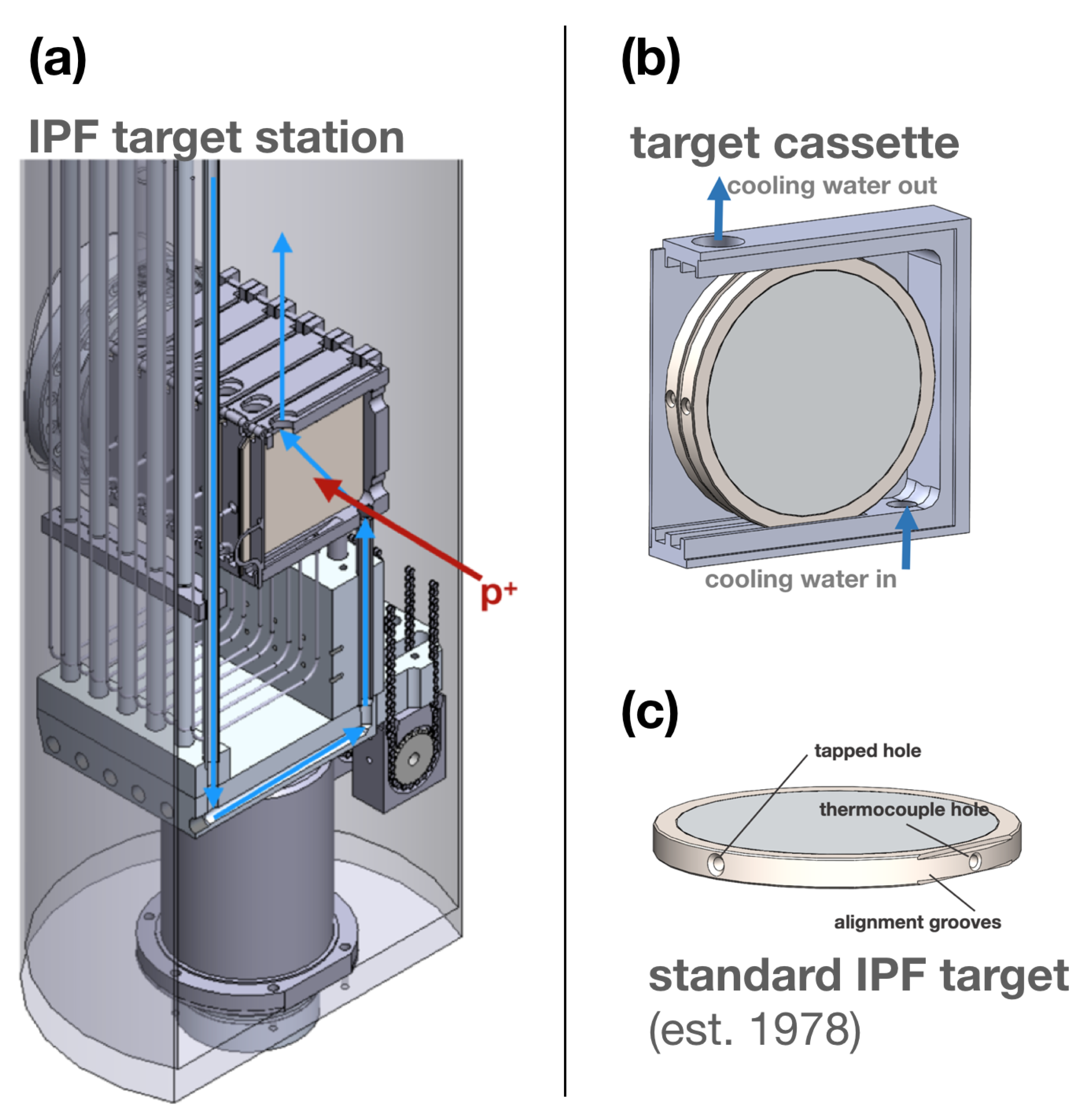
IPF consists of a 30 cm diameter, 8 m tall column of cooling water. The target station is located in the bottom of the water column at beam level. Above the water column, a shielded transfer hot cell is used to bring targets in or out of the facility and to move them in or out of the beam. Within the transfer cell, targets are inserted into one of six cassettes which are lowered into the cooling water column and down to target station by a chain drive. A total of 12 targets can be simultaneously irradiated at IPF—each cassette can hold a pair of up to 8 mm thick targets, separated by a 2.5 mm gap (see Figure 1b). When isotope production targets are not in use, helium gas targets are inserted to displace cooling water from the beam path, minimizing heat loads on the IPF cooling water heat exchanger. During irradiation, targets are submerged in the water column and housed in one of six cassettes through which recirculating cooling water is pumped (see Figure 1a,b). The cooling water flow of 114 L/min is routed through the station’s 8 water circuits, six of which each feed individual cassettes. The two remaining water circuits are used for radial cooling of the target station’s entrance and exit windows. Flow rates through individual cassettes are estimated to be between 7.2 and 23.4 L/min, depending on the location of the cassette. Cooling water temperature typically measures 25–28 C at the target.
A typical IPF target is shown in Figure 1c: two Inconel® 600 windows (0.127 mm thickness) are welded to either side of a ring-shaped stainless steel target frame (10.1 cm diameter, 8.4 mm thickness), sealing within the 8.2 mm thick, 7.6 cm diameter puck of target material (ex. a puck of molybdenum dioxide or potassium chloride salt) [27]). As shown in Figure 1, the targets interface with other IPF components in three ways: alignment grooves on the bottom of the frame fix the orientation of the target within the cassette; a thermocouple hole at the bottom of the target has a thermocouple inserted in it during irradiation to monitor target temperature; and a tapped hole in the side of the frame allows targets to be securely picked up and manipulated by a threaded rod. More details regarding the IPF facility and its targets are provided by Burgerjon et al. [27].
2.2. Proton Beam Parameters
For 6–7 months per year, BL1A typically operates with 100–110 µA of 480 MeV protons at extraction from the TRIUMF main cyclotron, with the ability to increase this up to 170 µA. Before reaching IPF, beam losses occur due to two beryllium muon production targets (T1 and T2). Depending on the thickness of these targets, the proton beam reaching IPF can have an energy between 451 and 472 MeV and a current that is reduced by 15–40% to 60–94 µA under typical operating conditions. The beam profile at IPF is measured by a multi-wire scanner located 2 m before IPF. The Gaussian beam typically has a 2σ width between 25 and 35 mm in the horizontal and vertical directions, depending on the beam tune and thickness of the T1 and T2 targets.
Due to the variability in the beam conditions at IPF and the desire to design an 225Ac production target that is compatible with all BL1A operating conditions, multiple operational cases are considered when modelling irradiations of the thorium targets. A symmetrical Gaussian beam shape is assumed, with 2σ beam widths between 15 and 40 mm. Currents between 60 and 120 µA are also considered. Beam energy is fixed at 454 MeV (the lowest estimated beam energy at IPF), since at 454–470 MeV a <4% change in beam energy negligibly affects isotope production rates and heat loads on the target as both cross-sections and stopping powers are relatively flat in this energy range [30,31].
2.3. Thorium Target
2.3.1. Design Considerations
Since safe and reliable 225Ac production requires the hermetic seal of the target to withstand any thermally induced stresses caused by the proton beam, the target design must also maximize heat transfer from the thorium to the cooling water through the hermetic seal.
Post-irradiation processing of the target also requires that the thorium be dissolved. While a previous IPF thorium target prototype used ThO2 [32], this is not suitable for routine 225Ac production, due to the high insolubility of ThO2 [33]. Thorium metal was chosen as the target material as it can be readily dissolved post-irradiation. The metal also has other advantageous properties such as a high melting point and high density.
While the high density of thorium metal provides greater scaleability for maximizing 225Ac production if simultaneous irradiation of larger thorium quantities are desired, current needs only require the irradiation of thin thorium foils <1 mm in thickness. Therefore, the 8 mm wide hermetic target casing used for decades at IPF had to be modified in this target design.
2.3.2. Mechanical Assembly
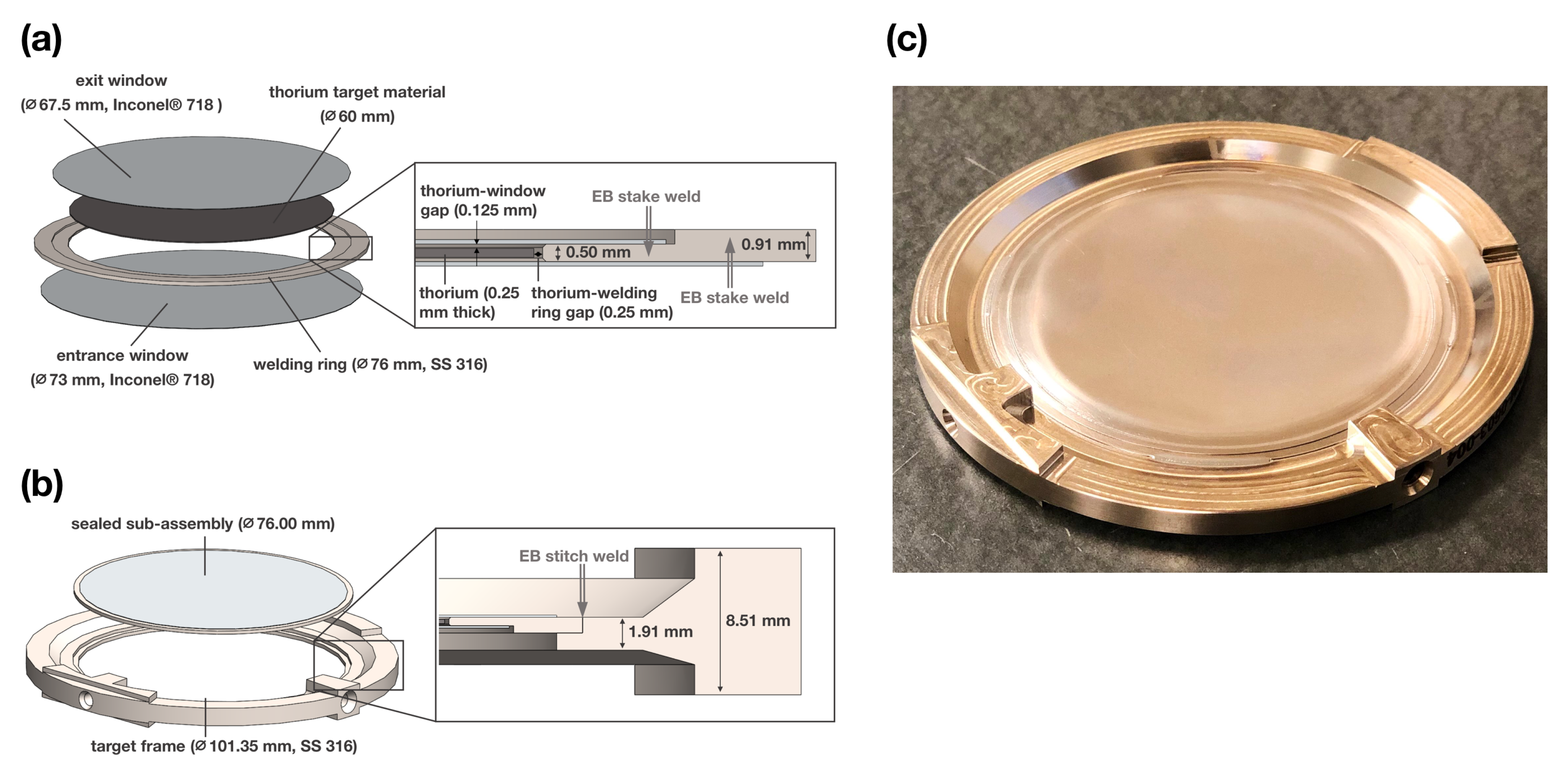
The thorium target consists of an stainless steel 316 (SS316) outer frame that interfaces with IPF cassettes, and the thorium target material that is sealed within the frame by two Inconel® 718 windows (0.127 mm thickness). Currently, the thorium metal target material consists of a 60 mm diameter, 0.25 mm thick foil, purchased from IBI Labs (International Bio-Analytical Industries, Inc., Boca Raton, FL, USA).
Sealing of the thorium within the target is done in two stages. First, the thorium is sealed within a target sub-assembly that consists of a thin inner welding ring (1 mm thick, 76 mm diameter), to which both windows are electron-beam (EB) welded (Figure 2a). The sub-assembly is then EB welded to the target frame (Figure 2b). A photo of the finished target is shown in Figure 2c.
Relevant material properties for the thorium, SS316, and Inconel® 718 components of the target assembly are shown in Table 1. Yield and ultimate strength values for Inconel® 718 were obtained from the materials certification provided by the manufacturer (American Special Metals, Coral Springs, FL, USA). Material composition by mass for each target component is provided in Table 2.
2.3.3. Areal Contact at Thorium-Window Interface
Contact between the thorium foil and the target assembly window is an important factor when considering how effectively the target will be cooled during irradiation, as the majority of power deposited in the target assembly is expected to be removed to the cooling water via heat transfer over this barrier.
As shown in Figure 2a, before the thorium is sealed within the sub-assembly, a 0.125 mm gap exists between the thorium and each window. Sealing of the foil under the vacuum provided by the EB welding chamber results in a first mode deflection of the target windows: atmospheric pressure acts on the sealed, evacuated sub-assembly, forcing the windows to bend inwards (visible in Figure 2c). This ensures contact between the thorium and windows at the center of the target where heat loads from the proton beam are highest.
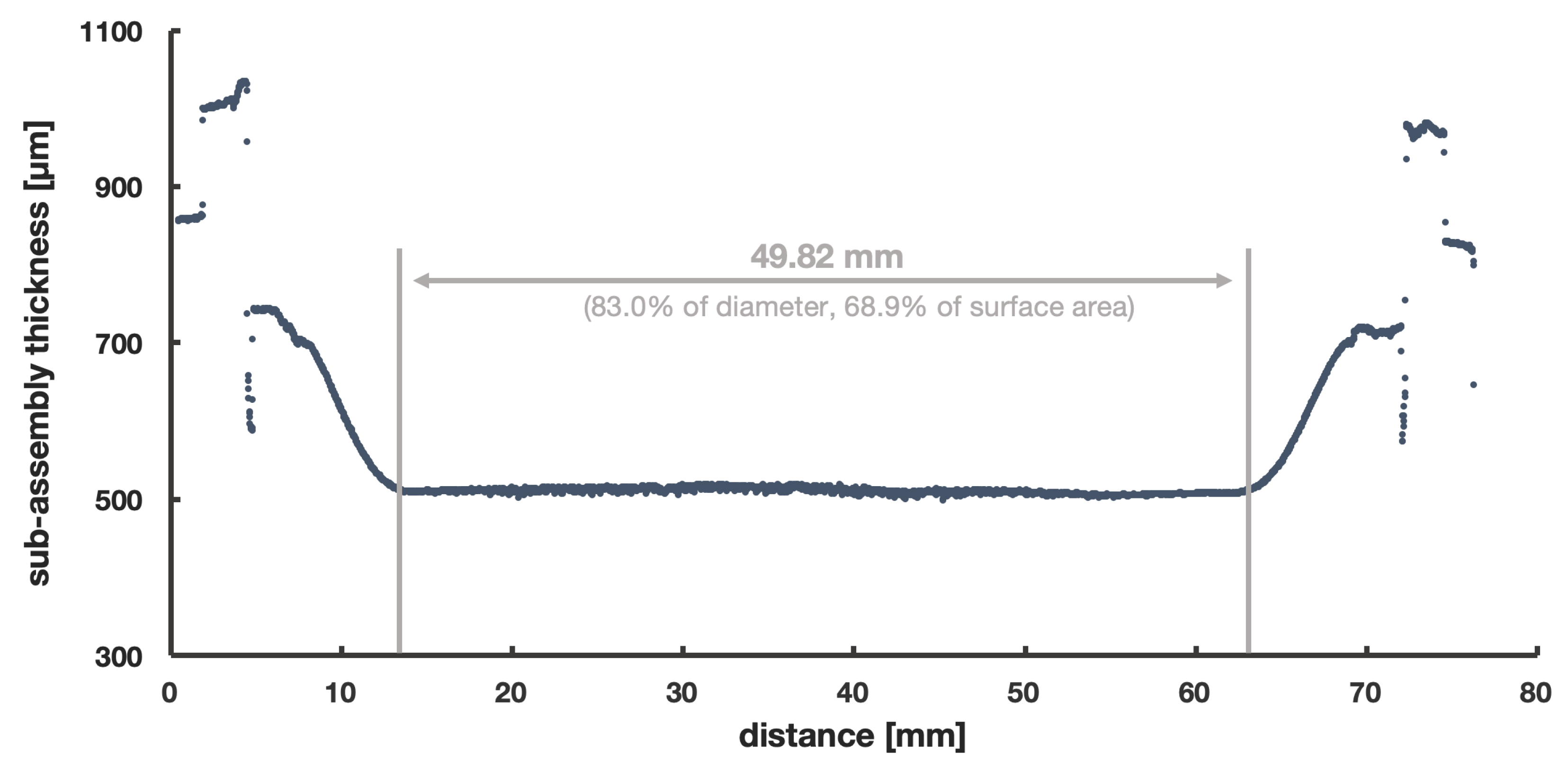
In order to measure the area for which the thorium and windows are in contact, the thickness of a manufactured sub-assembly was measured using a profilometer (Nanovea ST400). Shown in Figure 3, this indicates that the inner 49.8 mm of the thorium foil contacts the windows, as defined by the points where the windows stop deflecting inwards. These 49.8 mm represent 83.0% of the 60 mm thorium foil diameter, or 68.9% of the surface area. A second profile (not shown), made perpendicular to the one in Figure 3, also indicated 48.2 mm of contact (80.4% of the diameter).
For simulations of thorium target temperatures during irradiation, a conservative 45 mm wide contact region (75% of the diameter, and 56.3% of the surface area) is assumed. However, it should be noted that the amount of contact during the irradiation is expected to increase from measurements shown in Figure 3: while the profile measurement was done at atmosphere, additional pressure on the target windows will be present during irradiation due to the depth of the target in the cooling water column (8 m below the water surface).
2.3.4. Thermal Contact Resistance at Thorium-Window Interface
In addition to the contact area between the thorium and windows, the thermal contact resistance at this interface is also an important factor when considering how effectively the target will be cooled during irradiation. The greatest predictors of contact resistance are contact pressure, surface roughness, hardness, and yield strength. Thorium is soft and has a polished finish, so the contact resistance would likely be small. While limited data exists for thorium contact resistance measurements, comparisons can be made to similar materials. Several copper and aluminum alloys have similar properties to that of thorium; however, since aluminum values for contact resistance are higher it is more conservative to compare the thorium to aluminum (6000 series). The aluminum alloy with the closest material properties to thorium is aluminum 6061-T4 (Table 3). Table 4 also shows approximated contact resistances for several comparable metals. The aluminum-aluminum contact resistance is the highest of the comparable metals at 0.0005 mK/W. Other sources show a more detailed estimation of Aluminum 6061-T4 stress for the pressure range (0.1–0.2 MPa) the target will operate in [34]. Since these sources show a resistivity of below 0.001 mK/W the simulations will make the conservative approximation of 0.001 mK/W as the target contact resistance.
2.4. Thermomechanical Modelling
2.4.1. Power Deposition
Energy deposited by 454 MeV protons within each target component were simulated using SRIM [30] and results for each target component in MeV/proton are shown in Table 5. These values are then used to create power distribution profiles for each component that incorporate the beam’s current and Gaussian profile. A MATLAB script is used to generate these profiles and output them as contours that can be imported directly into ANSYS CFX (version 19.0). ANSYS CFX then interpolates between these contours to determine the 3-dimensional power deposition distribution for each target component. Please note that the beam is assumed to have a Gaussian shape symmetrical in the x- and y-directions, with beam width specified by the 2σ-value of the Gaussian. Since beam current and width may change between individual IPF irradiations (see Section 2.2), multiple beam width and current values are considered.
2.4.2. Thermal Modelling
ANSYS CFX simulations were used to model heat transport within the target during irradiation. Power deposition distributions and cooling water flow simulations were combined to model the thermal response of an irradiated and cooled target. Radiative heat transfer was excluded from the thermal simulations and only conductive heat flow was considered.
ANSYS CFX simulations used a turbulence model to represent the mixed laminar and turbulent flow conditions present inside the target cassette. This model does not deal with issues of flow recovery, unconfined flows, flow separation or flow reattachment. While flow recovery, flow separation, and flow reattachment were observed in simulations, the flow rate is low enough for these effects to be negligible. Therefore, the turbulence model is a robust, stable, and conservative model to use [36].
Properties of inlet cooling water flow across the targets were set to 28 C, and a total flow rate of 0.120 L/s per cassette was used (corresponding to the lowest calculated value for mass flow rate through a given cassette, as detailed in Section 2.1). Due to the absence of flow measurements for individual cassettes, flow sensitivity checks were conducted to determine the effects of reduced flow on the simulation results.
The numerical accuracy of the solutions was determined based on the approach found in the Journal of Fluid Engineering [37]. The technique implements the iterative process of decreasing mesh size and solving the simulation until temperature, heat transfer and flow changes are negligible between mesh changes. The Grid Converged Index is then used to estimate the rate of convergence of the solution and truncation errors. Based on this standard check, the maximum error in the simulated temperature results is 9 K for the target windows.
2.4.3. Mechanical Modelling
To evaluate potential damage to the target during irradiation, stresses for the thorium foil and target windows are analyzed using a linear stress-strain model. Greater importance is placed on the integrity of the windows that provide a hermetic seal around the target during irradiation—damage to the thorium foil alone is not considered a target failure. Use of a linear model reduces computation time but limits the accuracy of results to cases where simulated stresses are below the yield stress of the materials. Therefore, when assessing the potential for target failure, the maximum stress in the target windows is, conservatively, compared to the yield stress of Inconel® 718.
To further reduce computation time, simulations also assumed temperature independence of material properties within the target assembly. This introduces an additional limitation: results will only be accurate within temperature ranges for which critical material properties are constant. For the Inconel® windows—the components critical when evaluating potential for target failure—this can be assumed between 0 and 600 C. The most critical Inconel® 718 properties—the ultimate and yield strengths—drastically decrease above 600 C. Please note that other Inconel® 718 properties such as Young’s modulus, Poisson’s ratio, and thermal conductivity are also temperature dependent, but are mostly constant over the same 0 to 600 C range. Due to its rare and radioactive nature, similar material property temperature-dependence data is challenging to find for thorium.
In addition to thermally induced stresses in the target caused by the proton beam, the target also experiences stresses caused by atmospheric and hydrostatic pressures. Since the thorium is sealed within the sub-assembly under vacuum conditions, 0.1 MPa of atmospheric pressure is exerted on the Inconel® windows after the target is removed from the EB welding chamber. The windows experience an additional 0.1 MPa (0.2 MPa total) when submerged under 8 m of water in the IPF target station during irradiation.
In the centre of the target where the windows press against the thorium, this 0.2 MPa of stress is negligible compared to the stress caused by heat during irradiation (on order of 10 MPa). Higher stresses are experienced near the edge of the window in the region where it deflects across the edge of the welding ring. Since accurate modelling of stresses at such boundaries is challenging, tests of the target’s ability to withstand these pressures were conducted: after the target was placed in a helium pressure chamber at 0.5 MPa for 2 h, no damage was observed. Based on this result, atmospheric and hydrostatic pressures were neglected when modelling the stresses in the thorium target during irradiation.
Mechanical simulation boundary conditions were selected on the perimeter of the thermal loading region to determine conservative worst case stresses. Similar to methods described in Section 2.4.2, various iterations of mesh size and type were completed to determine the grid independence of the mechanical solution before final simulations were completed.
2.5. Yield Measurements
After test irradiations, the thorium foil was dissolved in 10 M HNO3 + 12.5 mM HF and evaporated to a thorium nitrate salt before re-dissolution in 80.0 mL of 1 M HNO3, in preparation for the radiochemical separation of 225Ac from the target (described in an upcoming publication). A small portion (<100 µL of the redissolved target was removed and analyzed by gamma ray spectroscopy with a N-type Co-axial HPGe gamma spectrometer from Canberra fitted with a 0.5 mm beryllium window. The detector was calibrated (energy and efficiency) with a 20 ml 133Ba and 152Eu source. The dead time was less than 2%. The amount of 225Ra produced was quantified using the 40 keV gamma line of 225Ra, while the amount of 225Ac produced was quantified using the 218 keV gamma line of 221Fr (secular equilibrium between 225Ac and daughter 221Fr can be assumed at the time of measurement).
3. Results and Discussion
3.1. Modelling and Sensitivity Analysis
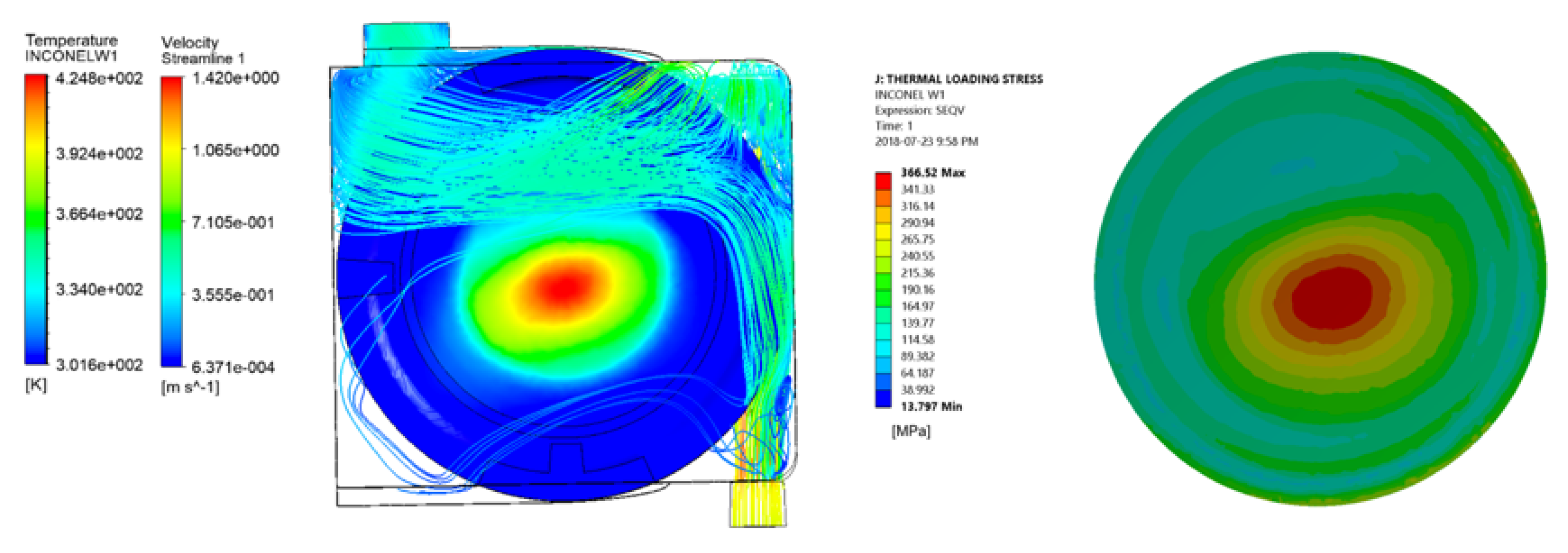
Table 6 shows the power deposited by the proton beam in each target component and the total sum, accounting for different beam shapes and beam currents. The beam current was varied from 60 µA to 120 µA and the beam width from 15 mm to 40 mm to cover all realistic cases. While the total deposited power scales with the beam current as expected, variation due to the beam width are 23% for all beam currents. It should be noted that as the beam width increases, the total power deposited in the thorium foil decreases since some of the proton beam is, undesirably, no longer hitting the thorium but hits the welding ring and frame instead. As an example, the resulting temperature and thermally induced stress for a 100 µA, 20 mm beam are shown in Figure 4, along with the cooling water flow profiles for a 0.12 L/s cassette flow. The maximum temperature and stress in the window follow roughly the beam shape.
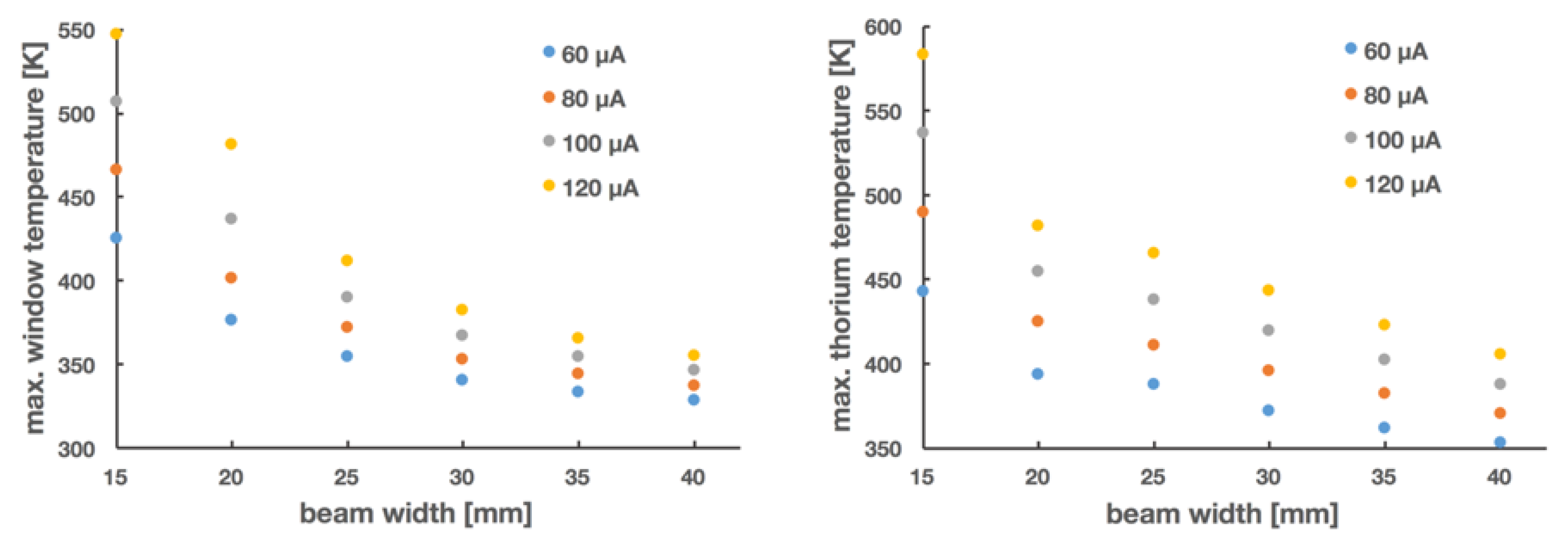
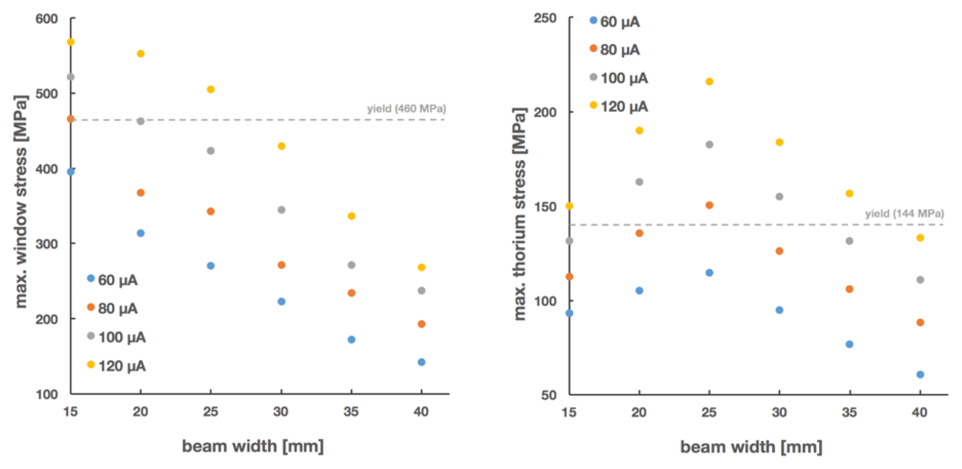
To summarize, thermal results determined by ANSYS CFX for all beam parameters considered, are shown in Figure 5. Similarly, the resulting maximal stresses on the thorium foil and Inconel® windows are shown in Figure 6. As expected, increases in beam current and decreases in beam width result in higher maximum temperatures and stresses on the target windows. However, using safety factors defined relative to each material’s yield strength, it can be seen that all beams of width >20 mm and <100 µA result in safety factors on the target window >1. Window temperatures also remain within the region of accuracy (<600 C) as defined in Section 2.4.3. These limits are well within the range of typical beam parameters at IPF (Section 2.2), meaning that 225Ac production at IPF can occur downstream of experimental users without any alterations to the beam or impact to other users of the beamline.
Some of the assumptions and input parameters to the thermomechanical simulations were simplified in order to reduce computation time. The temperature-independence of material properties, the linear stress-strain curves used for each material, and the mechanical simulation boundary conditions on the windows are examples that limit the accuracy of the simulations. However, these are balanced by conservative assumptions such as thermal contact resistance value used for the thorium-inconel interface. Combined with conservative stress limits on the hermetic seal of the target (relative to the yield stress of Inconel® 718 as opposed to the much higher ultimate stress), these assumptions provide confidence that these targets can be irradiated safely under the simulated conditions.
To test the sensitivity of the window and thorium foil temperature on the achieved thermal contact resistance between the thorium foil and the window, simulations were carried out varying the resistance from 0.0005 mK/W to 0.003 mK/W. The window temperature, cooled by the cooling water, is almost unaffected even for a heat transfer resistance underestimated by a factor of three. The thorium foil temperature, however, raises from 442 K to 506 K, potentially causing damage to the thorium foil.
Similarly, we varied the water flow in the cassette holding the targets from the nominal 0.12 kg/s down to 0.006 kg/s. Although the temperature of both the window and the thorium foil increase, even at a 95% reduction in water flow, the temperature only increases by less than 15%. Please note that a zero flow situation is interlocked by the target thermocouples, which would trip off the proton beam in the absence of cooling water flow.
3.2. Test Irradiations
Two irradiations of this target design have been completed to date. Both targets were irradiated for 36.5 h with an average beam current of 72.5 µA. Beam width was between 28–32 mm in the vertical and 30–35 mm in the horizontal directions.
After allowing targets to decay for 7 days, the thorium foil was removed from the target. In both cases, no damage, warping, or significant discoloration of the foil was observed.
The amount of 225Ac and 225Ra produced were measured via gamma spectroscopy. The decay corrected activity at EOB (average ± standard deviation) was (524 ± 21) MBq (14.2 mCi) and (86 ± 13) MBq (2.3 mCi) for 225Ac and 225Ra, respectively. These correspond to saturation yields of 72.5 MBq/µA for 225Ac and 17.6 MBq/µA for 225Ra.
While the 225Ac quantities produced so far may be modest, significant scaleability exists for 225Ac production at TRIUMF’s IPF. An increase in irradiation time to a full 225Ac half-life (9.9 days), would increase production by a factor of at least 8. The simultaneous irradiation of 12 targets is also possible. Combined, these two factors alone suggest 225Ac production at IPF could be readily scaled to at least 42 GBq (1.1 Ci) every 10 days, without requiring changes to the beam parameters or target design. Further increases in 225Ac and 225Ra yields could theoretically be achieved by increasing the proton beam current or the thickness of the 0.25 mm thick thorium foil (IPF targets can accommodate targets up to 8 mm thick); however, these would require a reassessment of the safety of such an irradiation—using the methodology presented herein—and a potential redesign of the target to prevent target failure.
The saturation yields for a 12-target irradiation would increase to 870 MBq/µA and 211 MBq/µA for 225Ac and 225Ra, respectively. Previous studies by others for the production of 225Ac via 232Th spallation have reported 225Ac saturation yields of 444 MBq/µA at 90 MeV and 1140 MBq/µA at 192 MeV [24,25]. However, these studies do not report yields for 225Ra production, which is known to be smaller at the reported energies of irradiation [31,38,39]. The 225Ra produced has the potential to not only provide approximately 0.8 MBq of 225Ac per 1 MBq of 225Ra [14], but also to provide generator-produced 225Ac with significantly reduced 227Ac impurities, a long-lived (t1/2 = 21.8 y) alpha-emitting radioisotope with low regulatory restrictions on waste disposal and accidental intake [32].
4. Conclusions
A target system for accelerator-based production of 225Ac from thorium metal at TRIUMF was presented and discussed. The thermomechanical response of the target to irradiation by the proton beam was thoroughly evaluated against conservative thresholds for target safety and the target was found to be compatible with the existing beam at typically received at the irradiation facility.
The target system was tested in two irradiations with 72 µA of 450 MeV protons. After removal from the beam neither the target windows nor the thorium foil showed signs of warping, discoloration or any other signs of excessive heat or mechanical stress. With this system we were able to produce (524 ± 21) MBq of 225Ac (14.2 mCi) and (86 ± 13) MBq of 225Ra (2.3 mCi) within a 36 h irradiation, corresponding to saturation yields of 72.5 MBq/µA for 225Ac and 17.6 MBq/µA for Raa. Longer irradiations to produce higher quantities are planned for the near future. It is estimated that the simultaneous irradiation of 12 targets over a 240 h period could produce 42 GBq of 225Ac and 7 GBq of 225Ra without requiring any changes to the target or beam parameters—further scaleability exists if these parameters would are also be changed.
Author Contributions
Conceptualization, P.S. and A.K.H.R.; methodology, L.M. and A.K.H.R.; formal analysis, A.L. and A.K.H.R.; data curation, A.K.H.R. and A.L.; writing—original draft preparation, A.K.H.R. and C.H.; writing—review and editing, C.H., P.S., and A.L.; supervision, C.H.; project administration, A.K.H.R.; funding acquisition, P.S.
Funding
TRIUMF receives funding via a contribution agreement with the National Research Council of Canada.
Acknowledgments
The authors would like to thank the following individuals for their valuable input into the design of the thorium target presented in this work: Ewart Blackmore, Gabriel Cojocaru, Tim Goodsell, Yetvart Hosepyan, Juergen Kaefer, Max Kinakin, Anders Mjos, Sam Varah, and Bob Welbourn.
Conflicts of Interest
The authors declare no conflict of interest.
References
- McDevitt, M.R.; Sgouros, G.; Finn, R.D.; Humm, J.L.; Jurcic, J.G.; Larson, S.M.; Scheinberg, D.A. Radioimmunotherapy with alpha-emitting nuclides. Eur. J. Nucl. Med. 1998, 25, 1341–1351. [Google Scholar] [CrossRef] [PubMed]
- Couturier, O.; Supiot, S.; Degraef-Mougin, M.; Faivre-Chauvet, A.; Carlier, T.; Chatal, J.F.; Davodeau, F.; Cherel, M. Cancer radioimmunotherapy with alpha-emitting nuclides. Eur. J. Nucl. Med. Mol. Imaging 2005, 32, 601–614. [Google Scholar] [CrossRef] [PubMed]
- Mulford, D.A.; Scheinberg, D.A.; Jurcic, J.G. The promise of targeted {alpha}-particle therapy. J. Nucl. Med. 2005, 46 (Suppl. 1), 199S–204S. [Google Scholar] [PubMed]
- Brechbiel, M.W. Targeted alpha-therapy: Past, present, future? Dalton Trans. 2007, 4918–4928. [Google Scholar] [CrossRef] [PubMed]
- Kim, Y.S.; Brechbiel, M.W. An overview of targeted alpha therapy. Tumor Biol. 2012, 33, 573–590. [Google Scholar] [CrossRef] [PubMed]
- Baidoo, K.E.; Yong, K.; Brechbiel, M.W. Molecular pathways: Targeted alpha-Particle radiation therapy. Clin. Cancer Res. 2013, 19, 530–537. [Google Scholar] [CrossRef] [PubMed]
- Elgqvist, J.; Frost, S.; Pouget, J.P.; Albertsson, P. The potential and hurdles of targeted alpha therapy—Clinical trials and beyond. Front. Oncol. 2014, 3, 324. [Google Scholar] [CrossRef] [PubMed]
- Miederer, M.; Scheinberg, D.A.; McDevitt, M.R. Realizing the potential of the Actinium-225 radionuclide generator in targeted alpha particle therapy applications. Adv. Drug Deliv. Rev. 2008, 60, 1371–1382. [Google Scholar] [CrossRef] [PubMed] [Green Version]
- Kratochwil, C.; Bruchertseifer, F.; Giesel, F.L.; Weis, M.; Verburg, F.A.; Mottaghy, F.; Kopka, K.; Apostolidis, C.; Haberkorn, U.; Morgenstern, A. 225Ac-PSMA-617 for PSMA targeting alpha-radiation therapy of patients with metastatic castration-resistant prostate cancer. J. Nucl. Med. 2016, 57, 1941–1944. [Google Scholar] [CrossRef] [PubMed] [Green Version]
- Jurcic, J.G.; Rosenblat, T.L. Targeted alpha-particle immunotherapy for acute myeloid leukemia. In 2014 American Society of Clinical Oncology Educational Book; American Society of Clinical Oncology: Alexandria, VA, USA, 2014; pp. e126–e131. [Google Scholar] [CrossRef]
- Kratochwil, C.; Giesel, F.L.; Bruchertseifer, F.; Mier, W.; Apostolidis, C.; Boll, R.; Murphy, K.; Haberkorn, U.; Morgenstern, A. 213Bi-DOTATOC receptor-targeted alpha-radionuclide therapy induces remission in neuroendocrine tumours refractory to beta radiation: A first-in-human experience. Eur. J. Nucl. Med. Mol. Imaging 2014, 41, 2106–2119. [Google Scholar] [CrossRef]
- Allen, B.; Singla, A.; Rizvi, S.; Graham, P.; Bruchertseifer, F.; Apostolidis, C.; Morgenstern, A. Analysis of patient survival in a Phase I trial of systemic targeted α-therapy for metastatic melanoma. Immunotherapy 2011, 3, 1041–1050. [Google Scholar] [CrossRef] [PubMed]
- Kratochwil, C.; Bruchertseifer, F.; Rathke, H.; Hohenfellner, M.; Giesel, F.L.; Haberkorn, U.; Morgenstern, A. Targeted α-Therapy of Metastatic Castration-Resistant Prostate Cancer with 225 Ac-PSMA-617: Swimmer-Plot Analysis Suggests Efficacy Regarding Duration of Tumor Control. J. Nucl. Med. 2018, 59, 795–802. [Google Scholar] [CrossRef] [PubMed]
- Robertson, A.K.H.; Ramogida, C.F.; Schaffer, P.; Radchenko, V. Development of 225Ac Radiopharmaceuticals: TRIUMF Perspectives and Experiences. Curr. Radiopharm. 2018, 11. [Google Scholar] [CrossRef] [PubMed]
- Zhuikov, B.L. Successes and problems in the development of medical radioisotope production in Russia. Phys. Uspekhi 2016, 59, 481–486. [Google Scholar] [CrossRef]
- Radchenko, V.; Engle, J.W.; Wilson, J.J.; Maassen, J.R.; Nortier, F.M.; Taylor, W.A.; Birnbaum, E.R.; Hudston, L.A.; John, K.D.; Fassbender, M.E. Application of ion exchange and extraction chromatography to the separation of actinium from proton-irradiated thorium metal for analytical purposes. J. Chromatogr. A 2015, 1380, 55–63. [Google Scholar] [CrossRef] [Green Version]
- Aliev, R.A.; Ermolaev, S.V.; Vasiliev, A.N.; Ostapenko, V.S.; Lapshina, E.V.; Zhuikov, B.L.; Zakharov, N.V.; Pozdeev, V.V.; Kokhanyuk, V.M.; Myasoedov, B.F.; et al. Isolation of Medicine-Applicable Actinium-225 from Thorium Targets Irradiated by Medium-Energy Protons. Sol. Extr. Ion Exch. 2014, 32, 468–477. [Google Scholar] [CrossRef]
- Morgenstern, A. Bismuth-213 and actinium-225—Generator performance and evolving therapeutic applications of two generator-derived alpha-emitting radioisotopes. Curr. Radiopharm. 2012, 5, 221–227. [Google Scholar] [CrossRef]
- International Atomic Energy Agency. Technicial Meeting on Alpha eMitting Radionuclides and Radiopharmaceuticals for Therapy; Technical Report; International Atomic Energy Agency: Vienna, Austria, 2013. [Google Scholar]
- Weidner, J.W.; Mashnik, S.G.; John, K.D.; Ballard, B.; Birnbaum, E.R.; Bitteker, L.J.; Couture, A.; Fassbender, M.E.; Goff, G.S.; Gritzo, R.; et al. 225Ac and 223Ra production via 800 MeV proton irradiation of natural thorium targets. Appl. Radiat. Isot. 2012, 70, 2590–2595. [Google Scholar] [CrossRef]
- Weidner, J.W.; Mashnik, S.G.; John, K.D.; Hemez, F.; Ballard, B.; Bach, H.; Birnbaum, E.R.; Bitteker, L.J.; Couture, A.; Dry, D.; et al. Proton-induced cross sections relevant to production of 225Ac and 223Ra in natural thorium targets below 200 MeV. Appl. Radiat. Isot. 2012, 70, 2602–2607. [Google Scholar] [CrossRef]
- Engle, J.W.; Mashnik, S.G.; Weidner, J.W.; Wolfsberg, L.E.; Fassbender, M.E.; Jackman, K.; Couture, A.; Bitteker, L.J.; Ullmann, J.L.; Gulley, M.S.; et al. Cross sections from proton irradiation of thorium at 800 MeV. Phys. Rev. C Nucl. Phys. 2013, 88. [Google Scholar] [CrossRef] [Green Version]
- Cutler, C.; Mausner, L. Energetic protons boost BNL isotope production TRIUMF targets alpha therapy. Cern Cour. 2016, 56, 32–35. [Google Scholar]
- Griswold, J.; Medvedev, D.; Engle, J.; Copping, R.; Fitzsimmons, J.; Radchenko, V.; Cooley, J.; Fassbender, M.; Denton, D.; Murphy, K.; et al. Large scale accelerator production of 225Ac: Effective cross sections for 78–192 MeV protons incident on 232Th targets. Appl. Radiat. Isot. 2016, 118, 366–374. [Google Scholar] [CrossRef] [PubMed]
- Griswold, J.R. Actinium-225 Production via Proton Irradiation of Thorium-232. Ph.D. Thesis, Univeristy of Tennessee, Knoxville, TN, USA, 2016. [Google Scholar]
- NorthStar Medical Radioisotopes. Production of Actinium-225 via High Energy Proton Induced Spallation of Thorium-232; Technical Report; NorthStar Medical Radioisotopes: Madison, WI, USA, 2011. [Google Scholar]
- Burgerjon, J.J.; Pate, B.D.; Blaby, R.E.; Page, E.G.; Lenz, J.; Trevitt, B.T. The TRIUMF 500 MeV, 100 uA Isotope Production Facility. In Proceedings of the 27th Conference on Remote System Technology, San Francisco, CA, USA, 12–16 November 1979. [Google Scholar]
- Bylinskii, I.; Craddock, M.K. The TRIUMF 500 MeV cyclotron: The driver accelerator. Hyperfine Interact. 2013, 225, 9–16. [Google Scholar] [CrossRef]
- Blackmore, E.W.; Dodd, P.E.; Shaneyfelt, M.R. Improved capabilities for proton and neutron irradiations at TRIUMF. In Proceedings of the 2003 IEEE Radiation Effects Data Workshop, Monterey, CA, USA, 25 July 2003. [Google Scholar] [CrossRef]
- Ziegler, J.F.; Ziegler, M.; Biersack, J. SRIM—The stopping and range of ions in matter (2010). Nucl. Instrum. Methods Phys. Res. Sect. B Beam Interact. Mater. Atoms. 2010, 268, 1818–1823. [Google Scholar] [CrossRef]
- Chadwick, M.; Herman, M.; Obložinský, P.; Dunn, M.; Danon, Y.; Kahler, A.; Smith, D.; Pritychenko, B.; Arbanas, G.; Arcilla, R.; et al. ENDF/B-VII.1 Nuclear Data for Science and Technology: Cross Sections, Covariances, Fission Product Yields and Decay Data. Nucl. Data Sheets 2011, 112, 2887–2996. [Google Scholar] [CrossRef]
- Robertson, A.K.H.; Ladouceur, K.; Nozar, M.; Moskven, L.; Ramogida, C.F.; D’Auria, J.; Sossi, V.; Schaffer, P. Design and Simulation of Thorium Target for Ac-225 Production. AIP Conf. Proc. 2017, 1845, 020019–1–020019–5. [Google Scholar] [CrossRef]
- Hyde, E.K. The Radiochemistry of Thorium; Vol. NAS-NS 300, Subcommittee on Radiochemistry, National Academy of Sciences–National Research Council: Berkeley, CA, USA, 1960. [Google Scholar] [CrossRef]
- Knovel Engineering Technical Reference Information Database. Available online: https://app.knovel.com/web/ (accessed on 13 February 2019).
- International, A. Properties and Selection: Nonferrous Alloys and Special-Purpose Materials; ASM International: Almere, The Netherlands, 1991; Volume 2, p. 1300. [Google Scholar] [CrossRef]
- Mohammadi, B.; Pironneau, O. Analysis of the K-Epsilon Turbulence Model; Wiley: Hoboken, NJ, USA, 1994. [Google Scholar]
- Journal of Fluids Engineering Editorial Policy Statement on the Control of Numerical Accuracy. Technical Report. Available online: https://www.asme.org/wwwasmeorg/media/ResourceFiles/Shop/Journals/JFENumAccuracy.pdf (accessed on 13 February 2019).
- Experimental Nuclear Reaction Data (EXFOR). Available online: http://www.nndc.bnl.gov/exfor/exfor.htm (accessed on 13 February 2019).
- ENDF: Evaluated Nuclear Data File. Available online: https://www-nds.iaea.org/exfor/endf.htm (accessed on 13 February 2019).
Figure 1.
(a) IPF target station at beam level, with six cassettes inserted into the beam. The arrows indicate cooling water flow direction; (b) An IPF cassette holding two targets; (c) A typical IPF target.
Figure 1.
(a) IPF target station at beam level, with six cassettes inserted into the beam. The arrows indicate cooling water flow direction; (b) An IPF cassette holding two targets; (c) A typical IPF target.

Figure 2.
(a) Target sub-assembly, including the thorium foil, welding ring, and entrance and exit windows. Note the location of EB welds that bind the windows to the welding ring, sealing the thorium within; (b) Welding of the sub-assembly to the target frame; (c) Photo of the thorium target. Note the inward deflection of the Inconel® 718 window.

Figure 3.
Plot of the thorium target sub-assembly thickness. Measurement of the inward deflection of the window, as also seen in Figure 2c, indicates the region for which the thorium and windows are in contact. The expected thickness in the centre of the sub-assembly (assuming contact of the thorium with both windows) is 504 µm.

Figure 4.
(a) Example of simulated flow streamlines and temperatures; and (b) stresses in the target entrance window for a 100 µA, 20 mm beam.
Figure 4.
(a) Example of simulated flow streamlines and temperatures; and (b) stresses in the target entrance window for a 100 µA, 20 mm beam.

Figure 5.
Maximum simulated temperatures within target window (left) and thorium foil (right) components during irradiations of varying beam current and width.
Figure 5.
Maximum simulated temperatures within target window (left) and thorium foil (right) components during irradiations of varying beam current and width.

Figure 6.
Maximum simulated stresses resulting from temperatures within window (left) and thorium (right) target components during irradiations. Please note that increase in thorium foil stresses as beam width increases (from 15 to 25 mm) is due to deposition of heat in regions of the thorium that are not in contact with the window.


Table 1.
Base properties at room temperature for target components.
| Property | Inconel® 718 | Thorium | SS 316 |
|---|---|---|---|
| Density (g/cm) | 8.19 | 11.72 | 8 |
| Young’s Modulus (GPa) | 199 | 72.4 | 193 |
| Thermal expansion coefficient (µm/mK) | 13 | 11.1 | 16.3 |
| Poisson’s ratio | 0.3 | 0.27 | 0.28 |
| Yield strength (MPa) | 460 | 144 | 290 |
| Ultimate strength (MPa) | 895 | 219 | 580 |
| Melting Point (K) | 1533 | 2028 | 1673 |
| Thermal conductivity (W/mK) | 11.1 | 13.86 | 14.6 |
Table 2.
Elemental composition of alloys used in L124 IPF targets.
| Material | Composition (% Mass) | |||||||||
|---|---|---|---|---|---|---|---|---|---|---|
| Cu | Cr | Fe | Mn | Si | C | S | Mo | Ni | P | |
| Inconel® 718 | 0.3 | 17 | 23.6 | 0.35 | 0.35 | 0.08 | 0.015 | 3.3 | 55 | 0.015 |
| SS 316 | - | 16 | 70 | 0.5 | 0.25 | 0.083 | 0.083 | 2 | 11 | 0.083 |
| thorium | >99.5% purity according to manufacturer and confirmed by ICP-MS analysis | |||||||||
Table 3.
Comparison of thorium to select aluminum and copper alloys in terms of material properties relevant to thermal contact resistance.
Table 3.
Comparison of thorium to select aluminum and copper alloys in terms of material properties relevant to thermal contact resistance.
| Material | Yield Strength (MPa) | Brinell Hardness |
|---|---|---|
| thorium | 144 | 60–90 |
| aluminum 6061-T4 | 146 | 65–89 |
| aluminum 2024-T4 | 395 | 120–150 |
| aluminum 7075-T6 | 503 | 150–191 |
| copper 1010 | 305 | 105–123 |
Table 4.
Thermal contact resistances for select materials under vacuum conditions.
| Interface | Thermal Contact Resistance (mK/W) |
|---|---|
| iron-aluminum | 0.00002 |
| copper-copper | 0.0001 |
| aluminum-aluminum | 0.00045 |
| stainless-stainless | 0.005 |
| ceramic-ceramic | 0.002 |
Table 5.
Energy deposited in thorium target components by 454 MeV protons.
| Component | Material | Thickness (mm) | Energy Deposited (MeV/Proton) |
|---|---|---|---|
| thorium foil | thorium | 0.25 | 0.423 |
| entrance window | Inconel® 718 | 0.127 | 0.21 |
| exit window | Inconel® 718 | 0.127 | 0.21 |
| target frame | SS 316 | 8.51 | 8.306 |
| welding ring | SS 316 | 0.91 | 1.466 |
Table 6.
Energy deposited in thorium target components by 454 MeV protons.
| Current (µA) | Width (mm) | Power Deposition in Target (W) | |||||
|---|---|---|---|---|---|---|---|
| Thorium | ent. Window | Exit Window | Welding Ring | Frame | Total | ||
| 60 | 15 | 25.42 | 12.63 | 12.63 | 0 | 0 | 50.68 |
| 20 | 25.28 | 12.63 | 12.63 | 0.01 | 0.05 | 50.61 | |
| 25 | 24.59 | 12.63 | 12.63 | 0.01 | 0.88 | 50.75 | |
| 30 | 23.16 | 12.63 | 12.63 | 0.17 | 4.06 | 52.64 | |
| 35 | 21.21 | 12.63 | 12.63 | 0.27 | 10.04 | 56.78 | |
| 40 | 19.08 | 12.61 | 12.62 | 0.35 | 17.63 | 62.29 | |
| 80 | 15 | 33.89 | 16.84 | 16.84 | 0 | 0 | 67.57 |
| 20 | 33.71 | 16.84 | 16.84 | 0.02 | 0.07 | 67.48 | |
| 25 | 32.79 | 16.84 | 16.84 | 0.02 | 1.18 | 67.67 | |
| 30 | 30.88 | 16.84 | 16.84 | 0.22 | 5.41 | 70.19 | |
| 35 | 28.28 | 16.84 | 16.84 | 0.36 | 13.39 | 75.7 | |
| 40 | 25.44 | 16.82 | 16.83 | 0.46 | 23.5 | 83.05 | |
| 100 | 15 | 42.36 | 21.05 | 21.05 | 0 | 0 | 84.46 |
| 20 | 42.14 | 21.05 | 21.05 | 0.02 | 0.09 | 84.35 | |
| 25 | 40.99 | 21.05 | 21.05 | 0.02 | 1.47 | 84.58 | |
| 30 | 38.6 | 21.05 | 21.05 | 0.28 | 6.77 | 87.74 | |
| 35 | 35.36 | 21.05 | 21.05 | 0.45 | 16.74 | 94.63 | |
| 40 | 31.8 | 21.02 | 21.04 | 0.58 | 29.38 | 103.82 | |
| 120 | 15 | 50.83 | 25.26 | 25.26 | 0 | 0 | 101.35 |
| 20 | 50.57 | 25.26 | 25.26 | 0.03 | 0.11 | 101.22 | |
| 25 | 49.19 | 25.26 | 25.26 | 0.03 | 1.77 | 101.5 | |
| 30 | 46.32 | 25.26 | 25.26 | 0.33 | 8.12 | 105.29 | |
| 35 | 42.43 | 25.25 | 25.25 | 0.53 | 20.08 | 113.55 | |
| 40 | 38.16 | 25.22 | 25.25 | 0.69 | 35.26 | 124.58 | |
© 2019 by the authors. Licensee MDPI, Basel, Switzerland. This article is an open access article distributed under the terms and conditions of the Creative Commons Attribution (CC BY) license (http://creativecommons.org/licenses/by/4.0/).
Share and Cite
MDPI and ACS Style
Robertson, A.K.H.; Lobbezoo, A.; Moskven, L.; Schaffer, P.; Hoehr, C. Design of a Thorium Metal Target for 225Ac Production at TRIUMF. Instruments 2019, 3, 18. https://doi.org/10.3390/instruments3010018
AMA Style
Robertson AKH, Lobbezoo A, Moskven L, Schaffer P, Hoehr C. Design of a Thorium Metal Target for 225Ac Production at TRIUMF. Instruments. 2019; 3(1):18. https://doi.org/10.3390/instruments3010018
Chicago/Turabian StyleRobertson, Andrew K.H., Andrew Lobbezoo, Louis Moskven, Paul Schaffer, and Cornelia Hoehr. 2019. "Design of a Thorium Metal Target for 225Ac Production at TRIUMF" Instruments 3, no. 1: 18. https://doi.org/10.3390/instruments3010018