1. Introduction
99mTc is a radionuclide widely used in Conventional Nuclear Medicine diagnostic examinations. It is routinely eluted from portable generators containing the parent radionuclide
99Mo, coming from highly-enriched (>80 wt.%
235U) uranium targets irradiated in nuclear fission reactors. Once separated from the
235U fission products and further purified,
99Mo is loaded onto an alumina column inside the portable generator.
99mTc-radiopharmaceuticals are then directly prepared in hospital radiopharmacies by adding the
99mTc-pertechnetate eluted from generators directly in lyophilized “kits”, following the manufacturer instructions and quality control specifications to get an injectable product. Approximately 95% of the world’s production of
99Mo is provided by few ageing nuclear reactors, whose unplanned outages have already caused global shortages in the last decade, even recently (November 2018) [
1]. In order to mitigate this problem in the mid-long term, alternative
99mTc production routes have been intensively investigated all over the world.
A dedicated CRP (Coordinated Research Project) program launched by the International Atomic Energy Agency (IAEA) in 2011–2015 [
2,
3] was dedicated to the
99mTc/
99Mo accelerator-based production routes. Main CRP outcomes have revealed that the direct
99mTc production, through the
100Mo(p,2n) nuclear reaction, starting from highly
100Mo-enriched (i.e., enrichment >99.5%) molybdenum targets is the most promising approach [
3,
4,
5,
6,
7]. In this context, the optimal proton energy range 10–25 MeV, able to provide sufficient amounts of the radioisotope with impurity level within the limits defined by corresponding European Pharmacopeia [
8], has been identified [
6,
9]. Furthermore, recommended target thickness and irradiation times for optimized production at different irradiation energies (15, 20 and 25 MeV) have been calculated by Esposito et al. (2013) [
10].
The purpose of the TECHnetium direct-production in hOSPital (TECHN-OSP) research project at INFN [
4,
10,
11,
12] was the development of a technology able to produce GBq amounts of
99mTc through the (p,2n) nuclear reaction route on
100Mo-enriched metal targets. This approach could provide the daily routine supply by exploiting the existing medical cyclotron network in Italy.
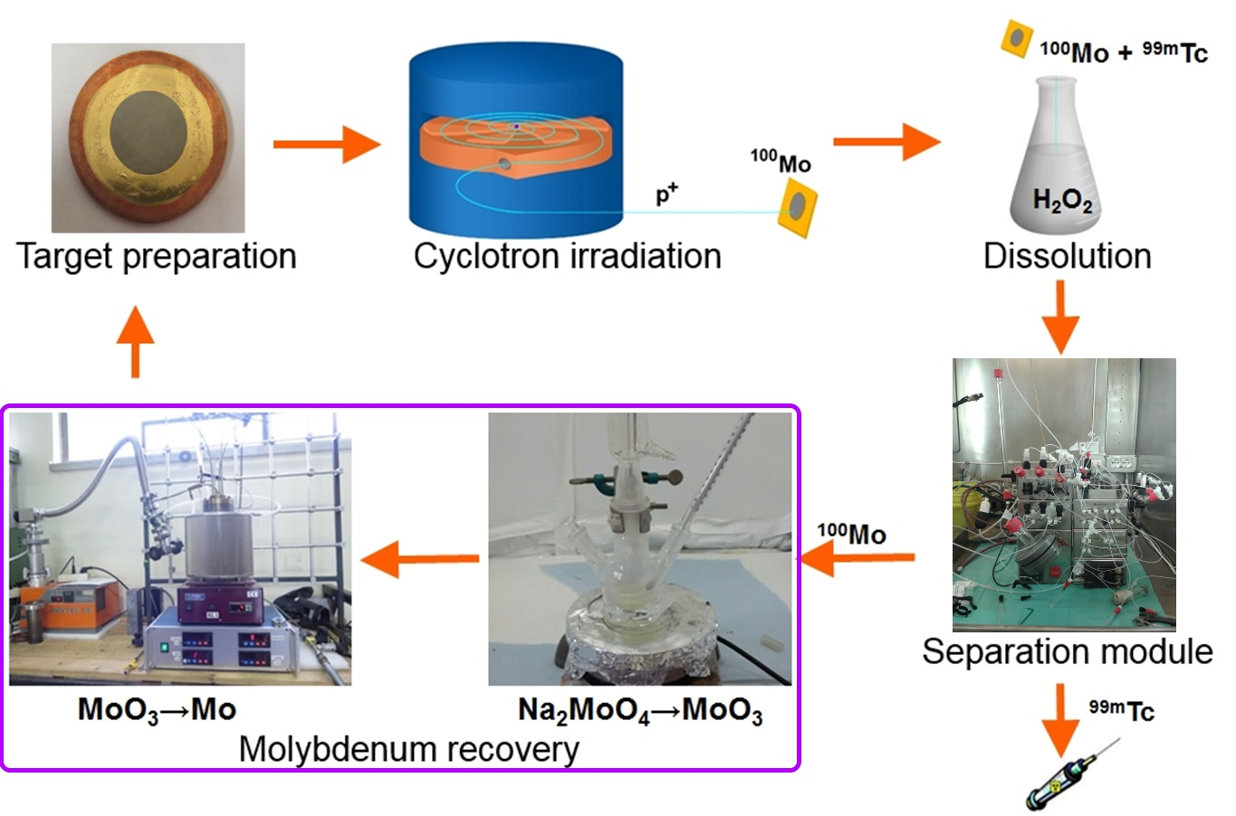
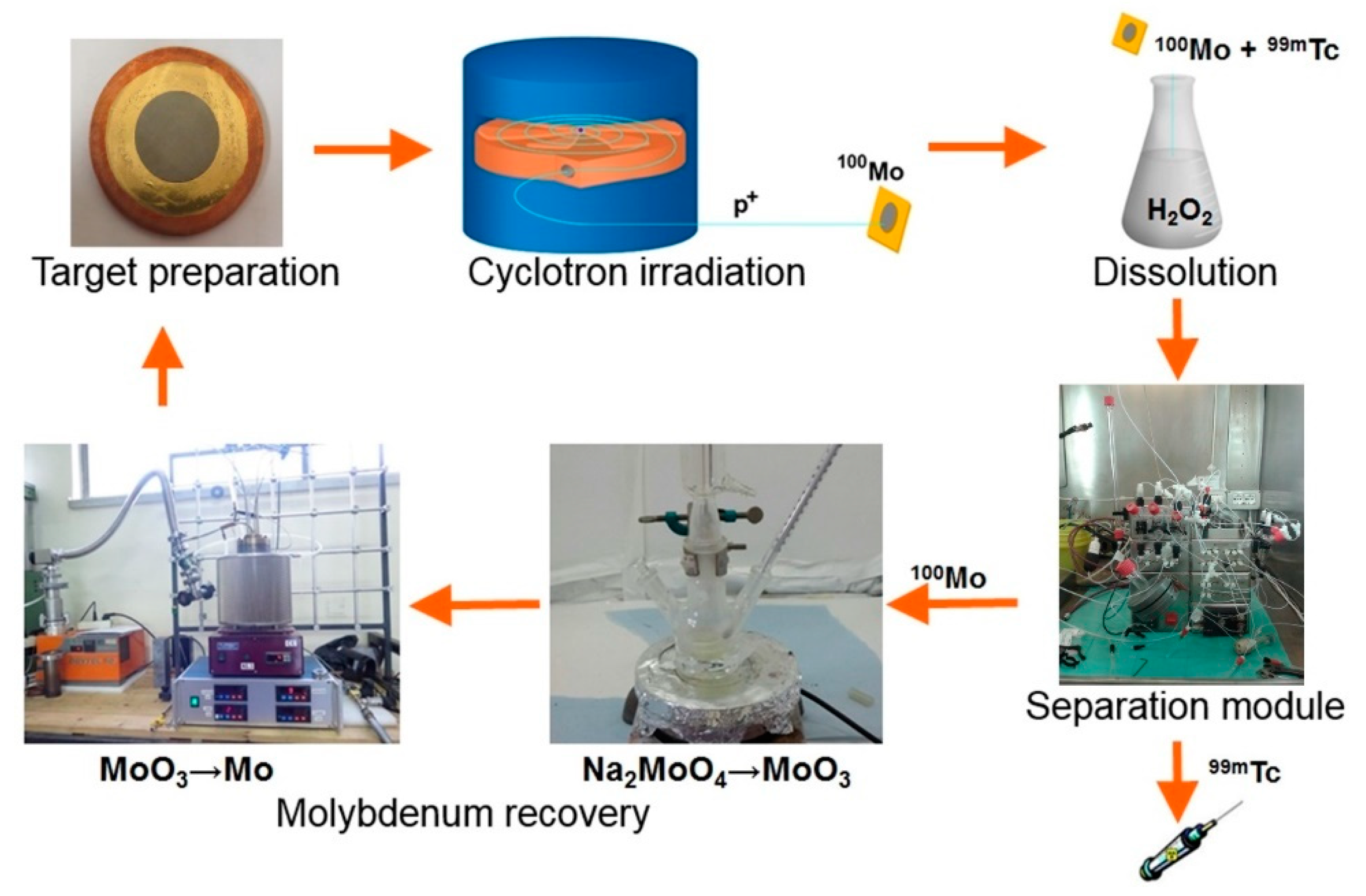
A cyclotron-based
99mTc closed-loop production cycle includes the following steps, as shown in
Figure 1. (i)
100Mo target manufacturing, (ii) target irradiation with a proton cyclotron, (iii) dissolution of
100Mo layer containing
9xTc radionuclides (plus Nb, Zr impurities) in the concentrated H
2O
2 solution, (iv) separation/purification of
99mTc from
100Mo and by-products by a developed dedicated separation module, and (v) recovery of the costly
100Mo material remaining as the “waste” after the separation procedure [
4,
12].
As regards the 100Mo metal target, several configurations have been developed and tested in the framework of the TECHN-OSP project:
In order to meet the requirements for a fast and efficient dissolution, extraction and purification of
99mTc yielded from
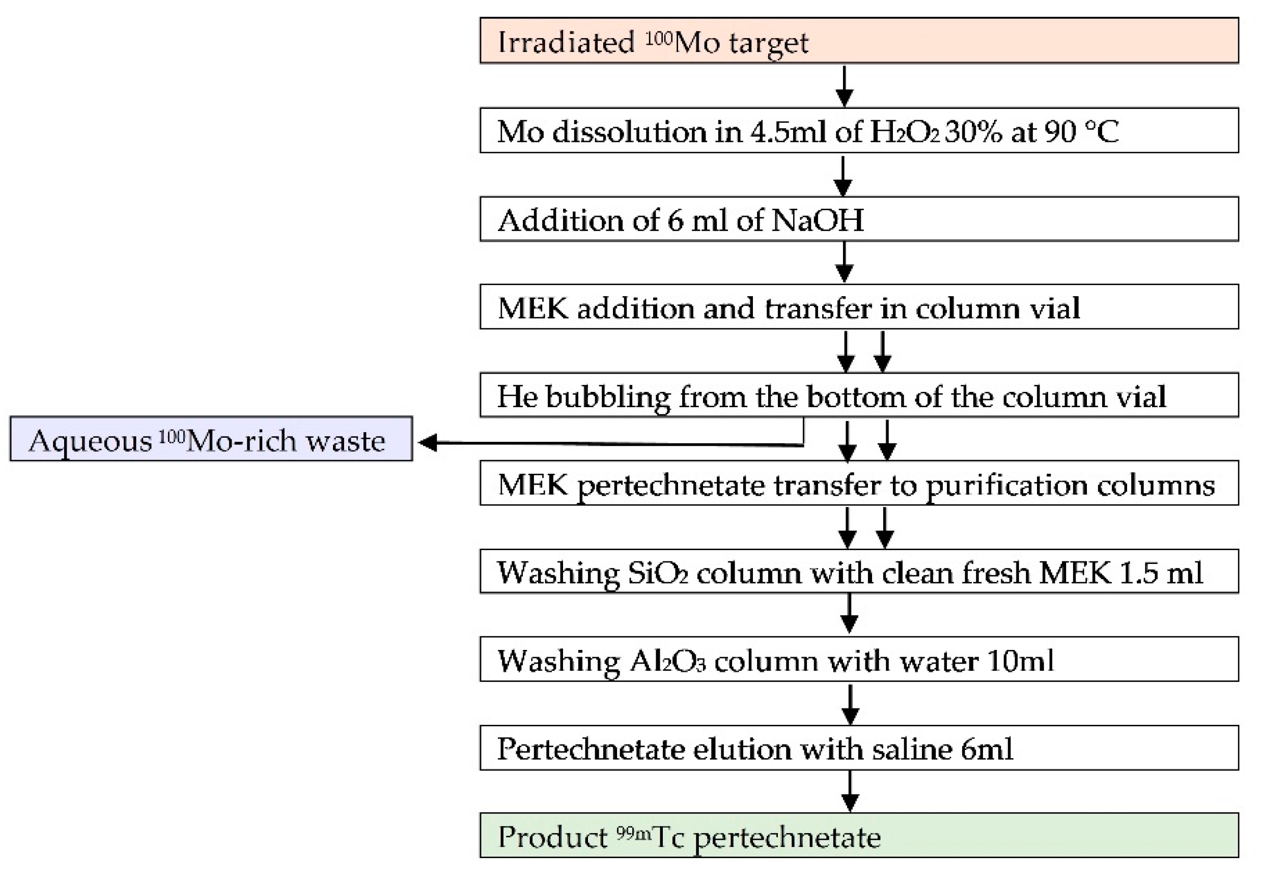
100Mo-enriched molybdenum metallic target irradiation, a remotely controlled module based on the Solvent Extraction (SE) technique has been developed. After the irradiation, the targets were processed according to a protocol presented in
Figure 2 and described in details by Martini et al. [
12]. All quality control procedures on the final products, radiolabeling, in vivo and on phantom imaging studies with a clinical gamma camera, have been conducted as well [
16].
In order to make the cyclotron-based 99mTc production costs affordable, the expensive 100Mo-enriched material should be recovered from the separation module waste with the aim to be reused for the preparation of new targets, thus closing the production cycle.
Therefore, the goal of this work was to develop a molybdenum material recovery procedure under metallic form, starting from the isotope-rich “waste” fraction from the dedicated separation module [
4,
12], which has been cited as the most efficient among the ones reviewed in the work by Gumiela et al. [
17]. We applied a two-step procedure, which consists of the conversion of sodium molybdates present in the waste fraction into MoO
3, then followed by further reduction of molybdenum oxide into metallic molybdenum.
2. Materials and Methods
In order to simulate the Mo-rich waste coming from the radiochemical separation module [
12], 304.2 ± 3.3 mg of natural Mo (100 µm thickness foils, 99.95% purity purchased from Advent Research Materials Ltd., Eynsham, Oxford, England) went through the automatic radiochemical processing as described in
Figure 2. Briefly, molybdenum was dissolved in 4.5 mL 30% H
2O
2 at 90 °C in ~30 min; then 6 mL of 6M NaOH were added to the solution, and the same procedure applied in the case of SE of technetium from the solution was repeated twice using methyl ethyl ketone (MEK) [
12]. The residual aqueous Mo-rich solution, containing molybdate and polymolybdate species, was stored in glass vials, and water was removed by evaporation just before using it for the recovery studies. The residue was then washed with ethanol, filtered and dried at room temperature obtaining 0.79 ± 0.18 g of precipitate. In the following sections, it will be mentioned as molybdates mixture.
2.1. MoO3 Recovery from Mo-Rich Module “Waste”
The first step of molybdenum recovery is the conversion of sodium molybdates mixture to molybdic acid and MoO
3. The experiment has been performed using Mo-rich “waste” coming from the separation module [
12], standard chemical glassware, and commercially available chemical compounds: HCl, 37%, p.a. grade, Aldrich (Darmstadt, Germany); HNO
3, 65%, p.a. grade, Sigma Aldrich S.r.l. (Milan, Italy); and NH
4OH, 30%, p.a. grade, Carlo Erba (Cornaredo, Italy).
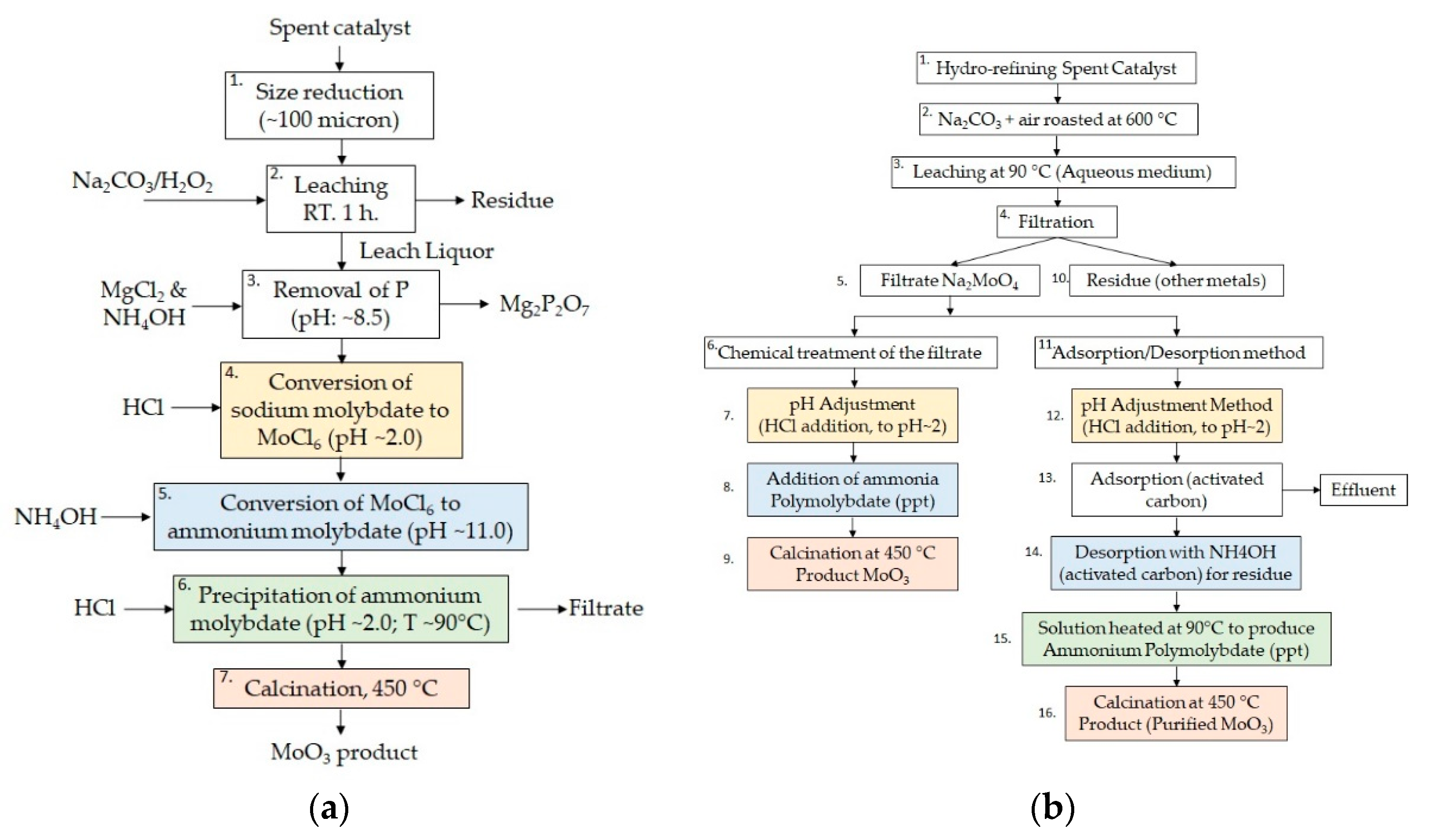
In order to achieve the highest recovery yield and purity, different techniques were tested (recipes 1–4) as described in the following section. The main approach used for MoO
3 recovery is known as the Mo-based “spent catalyst regeneration” procedures. Two methods were proposed by Park [
18] (
Figure 3a) and Kar [
19] (
Figure 3b). In both processes, the key steps interesting for the present recovery study, start from the conversion of ammonium molybdate in MoCl
6 by HCl treatment (step 4 on
Figure 3a and steps 7 and 12 on
Figure 3b). Then, ammonium hydroxide at controlled pH is added in order to obtain ammonium molybdate (step 5 on
Figure 3a and steps 8 and 14 on
Figure 3b). Afterwards, ammonium molybdate is precipitated by varying the solution pH (step 6 on
Figure 3a and step 15 on
Figure 3b) and calcinated at 450 °C to finally produce the pure MoO
3 product (step 7 on
Figure 3a and steps 9 and 16 on
Figure 3b).
2.1.1. Spent Catalyst Approach
Recipe MoO3-1. Into ~0.5 g of the dry Mo-rich “waste” coming from the separation module, 15 mL of 0.1M hydrochloric acid were added. The solution became yellow as a result of MoCl6 production at pH = 2. Then, 50 mL of 1M NH4OH were added to the solution, and the color turned blue/transparent at pH = 10.6. After heating the solution to 80 °C, the pH was observed to decrease to 9.5, owing to ammonia release. The precipitate was centrifuged for 8 min, recovered, and finally dried in vacuum overnight at 40 °C. The weight of the obtained pale yellow powder was 0.4 g.
2.1.2. Spent Catalyst Approach, Nitric Acid
Recipe MoO3-2. Into ~0.5 g of the product coming from the separation module 2–3 mL of 5M HNO3 and 10 mL of deionized water were added. The solution became yellow at pH = 0 (lower limit of pH-meter). Then, concentrated NH4OH was added dropwise to the solution until pH = 2, and the color turned yellow-green. The last drop of ammonium hydroxide changed the pH to 5.3 (desired pH = 2.5–3). The solution became pale blue after heating at 80 °C for 2 h and precipitation of white flakes occurred. The precipitate was centrifuged for 8 min, washed twice with 10 mL of ethanol, and dried in vacuum overnight at 40 °C. The weight of the obtained white powder was 0.11 g.
2.1.3. Direct Precipitation with Nitric Acid
Recipe MoO3-3. Into ~0.13 g of the product coming from the separation module 3–5 mL of 5M HNO3 (excess) were added. The mixture was heated up in reflux mode at 95 °C for 7 h. Then, the liquid was evaporated and the solid was washed twice with 15 mL of a mixture of EtOH:H2O (3:1 volumetric), prior to centrifugation at 4000 rpm for 8 min. The precipitate was dried in vacuum overnight at 40 °C, giving 0.082 g of white powder.
Recipe MoO3-4. 0.7 g natMo foil of 250 µm thick (99.99% purity, Goodfellow, Cambridge Ltd., Huntingdon, England) was dissolved in 15 mL of 30% H2O2 at 90 °C. The dissolution went on for ~20 min. When the solution was cooled down to 50 °C, 5 mL of 6 M NaOH was added to the solution and it was maintained for 30 min in order to simulate the process in a module. Hence, 25 mL of 5 M HNO3 (excess) was added to the solution. The mixture was heated up in reflux mode at 95 °C overnight. After evaporation, a white precipitate was obtained and washed with several portions of distilled water (15 mL, 3 × 7.5 mL). Then, the precipitate was dried in vacuum overnight at 40 °C giving 0.986 g of white powder.
2.2. MoO3 Reduction System
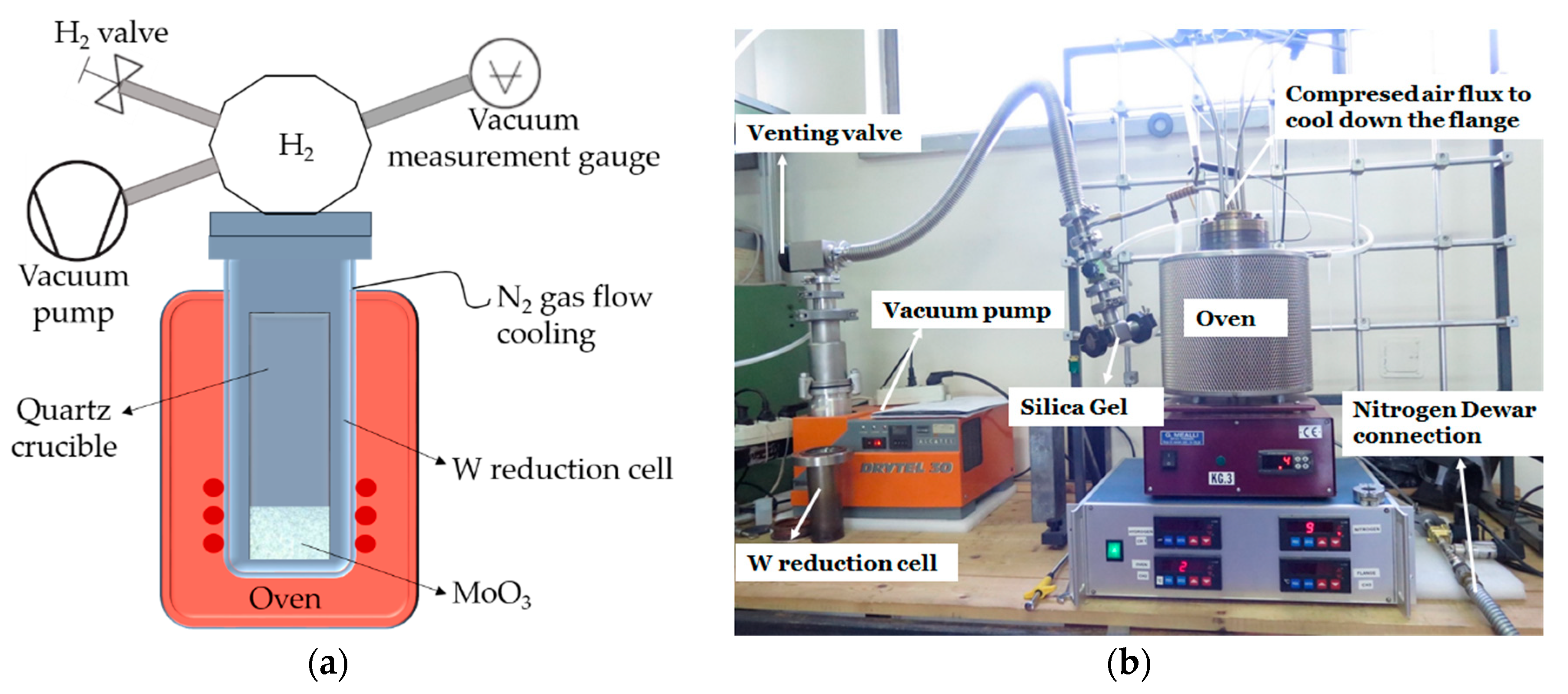
The second step of the closed-loop technology (i.e., the enriched molybdenum recovery process) is the molybdenum oxide reduction to metal, as described above. It was carried out using a dedicated hydrogenation reactor system. The apparatus is schematized in
Figure 4a and it is composed of a vacuum system, a furnace, a tungsten reduction cell filled with hydrogen, a liquid nitrogen Dewar, and a process data acquisition system.
While other groups have used laboratory-scale hydrogenation systems [
20] where the reduction process requires a constant hydrogen flow (i.e., an open system), in the present work we applied a different recovery method, using a batch overpressure reactor (i.e., a closed system). This approach has been chosen to fulfil safety regulations operating at LNL. Moreover, it is expected to be effective since the amount of oxide to be treated is lower with respect to the experiments presented by other groups. In order to shift the equilibrium towards the products in the chemical reaction, two techniques were simultaneously used: (i) carrying out the experiment in a hydrogen overpressure condition and (ii) condensing and capturing the water released during reduction by an appropriate amount of silica gel. Therefore, the reduction capability of the system depends on the maximum amount of hydrogen that can be inserted in safety conditions and on the water adsorption capability of the dried silica gel trap.
The full reduction system prototype developed in present work is schematically shown in
Figure 4b. During reduction experiments, MoO
3 was placed in a quartz crucible inside the tungsten reduction reactor with the total volume (including the volume inside the tubes before the valves) of ~1.2 L. The system was pumped down to remove air, and then hydrogen in overpressure was inserted by the gas valve.
The resistive furnace was used to heat up the reduction cell. Nitrogen gas released from the liquid nitrogen (LN2) Dewar was used for cooling down both the tube to condensate the water produced during the reaction and the tungsten reduction cell external walls. The nitrogen flux valve opened automatically when the oven temperature exceeded 250 °C. Silica gel (~10 g) was placed in a box inside the vacuum system for trapping the produced water. Compressed air was used to cool down the flange that closes the reduction cell on the top.
The Alcatel Drytel 30 (Anaheim, CA, USA) oil-free multistage high vacuum pumping system composed of a 7.5 L/s turbo drag pump and a 1 m3/h diaphragm pump was used for preliminary evacuation of the reduction cell. The Drytel 30 can operate from atmosphere to ~1 × 10⁻⁶ mbar, with a maximum pumping speed of 16 cfm (~27 m3/h) in the high vacuum range.
The 1400 W resistive melting furnace (Giuseppe Mealli S.r.l., Firenze, Italy) was used as a heating source for the reduction process. It is equipped with Kanthal (Hallstahammar, Sweden) resistors to ensure high temperatures and long duration. The thermal insulation is made of ceramic fiber in order to achieve rapid heating in combination with low power consumption. The oven can reach a maximum temperature of 1150 °C.
The reduction reactor was realized in a tungsten–copper-sintered composite material allowing to combine the high melting temperature of tungsten with the good machinability of copper. Nitrogen gas flow was passing around the external walls of the reduction cell in order to minimize its oxidation at elevated temperatures.
The main parameters controlled during the process included
oven temperature (0–1100 °C);
flange temperature (0–500 °C);
hydrogen pressure (0–8000 mbar absolute);
nitrogen pressure (2–2000 mbar absolute).
A dedicated program written in Java language (version 1.7) was used to control the reduction system. It allowed to set up the multistep heating process. The heating parameters are shown in
Table 1.
In step four, the temperature was kept constant for X hours, depending on the starting amount of MoO3. The heating parameters were modified, directly by the user during the process, through the GUI (graphical user interface). In case of emergency, a button allowed to immediately stop the process. If the flange temperature exceeds 350 °C, the program interrupts the process and the cooling starts.
The maximum amount of MoO3 powder that can be reduced using 2500 mbar H2 (270 mg) is 2.7 g (18 mmol). In this case, the amount of H2 used for reduction is 108 mg. When the process is finished, H2 final pressure of 1500 mbar (~1685 mbar theoretical) is obtained, thus maintaining the requirement of overpressure. The increase of the MoO3 load is possible: in this case, the volume of the apparatus should be increased proportionally in order to maintain the corresponding hydrogen overpressure after the reduction. It should be also taken into account that the maximum pressure achieved inside the new apparatus during the process has to be controlled for the safety issue.
2.3. Analysis of the Products
The applied analytical techniques to characterize the recovery and reduction products comprised X-ray diffraction (XRD) and scanning electron microscopy equipped with energy-dispersive spectroscopy (EDS-SEM).
XRD analysis has been performed with X’Pert Philips PW3040/60 diffractometer equipped with 1.54 Å Cu-Kα X-ray in θ/θ scanning mode. The scans were taken at 40 kV, 40 mA of Cu-Kα X-ray gun. The PW3071/xx Bracket sample stage was used in reflection mode.
For powders analysis, previously grinded in agate mortar Si zero-background sample holder was used. A semiquantitative analysis with X’Pert HighScore software was applied without any additional calibration. The outcome of XRD analysis is supported and completed by SEM-EDS investigation in order to fully investigate both crystalline and amorphous phases. Moreover, the results in terms of structure, composition and quantification have been compared with those expected from the involved chemical reactions.
Fei (former Philips) Scanning Electron Microscope SEM XL-30 equipped with the QUATNTAX energy-dispersive X-ray spectrometer of BRUKER (Billerica, Massachusetts, United States) were used for analysis of powders. It should be mentioned that the inaccuracy of the quantitative elemental analysis by EDX method is not less than 5% [
21].
Furthermore, the quantification due to mass change can be considered the most precise quantification method, provided an evidence that the set of the reactions and the products has been correctly identified. For the reduction of MoO
3, it was considered that the products could contain Mo and MoO
2 also on the basis of previous literature data [
20,
22]. Thus, only two possible reactions were taken into account:
In order to know the correct mass of the precursor, MoO3 was baked in the vacuum oven to remove water traces before weighing.
3. Results and Discussion
3.1. MoO3 Recovery from Mo-Rich Separation Module “Waste”
The starting material for the recovery procedure developed in the present study was coming from the separation module treatment of natural molybdenum foils. The module and the dissolution procedures are described in details by Martini et al. [
12]. According to the EDS analysis of the dried Mo-rich “waste” fraction from the module, it contained mainly Mo, Na, and O, with a huge excess of Na in respect to Mo. According to the XRD analysis, the mixture contained sodium molybdate Na
2MoO
4·, disodium dimolybdate Na
2Mo
2O
7, sodium tetramolybdenum hexoxide NaMo
4O
6, and sodium peroxide Na
2O
2 (from partial conversion of sodium hydroxide NaOH).
Following the literature approach called “spent catalyst regeneration” (see Recipe MoO3-1) a white-yellowish powder was obtained, containing Mo, Na, O, N, and Cl according to EDS analysis. Hence, we can suggest that MoCl6, Na2MoO4(H2O)x, and (NH4)2MoO4(H2O)y were present on the basis of starting reagents and chemical reactions involved. Thus, the applied procedure appeared to be not efficient to transform all sodium molybdate from the mixture coming from the separation module into ammonium molybdate.
In order to minimize the amount of MoCl6 impurity, hydrochloric acid was replaced by nitric acid (see Recipe MoO3-2). According to EDS analysis, ~2% Na and ~11% Mo were still detected in the product. Thus, the second method also did not provide the full conversion of sodium molybdate into ammonium molybdate as expected.
The last method proposed here, described in Scheme (3), included a direct conversion to molybdenum oxide and molybdic acids, thus skipping the ammonium molybdate step (see Recipe MoO
3-3).
After precipitation, molybdic acids and sodium nitrate were separated on the basis of different water solubility [
23]. Then, the solid was dried in a vacuum and analyzed by EDS and XRD. The structural analysis confirmed the presence of MoO
3 and Na
2MoO
4, while the EDS analysis led to quantify 0.3% Na and 15% Mo, thereby suggesting an enhanced separation efficiency with respect to previous experiments.
Furthermore, it has to be noted that Si impurity was detected in all the products coming from the separation module. It was supposed that Si impurity was produced by storing the product (Mo-rich waste from separation module) in glass vessels for several months’ (simulating the way to operate with enriched material). In fact, sodium molybdate fraction has a high concentration of residual sodium hydroxide, thus, glass corrosion is likely to occur. It is worth to highlight that for the repeated cycles of recovery the absence of the impurities is a crucial factor. In particular, in the case of irradiation of recovered Mo with traces of Si at 10–25 MeV a set of undesired reaction channels can be opened. In order to avoid the described problem and unambiguously identify the source of Si the process of dissolution was reproduced starting from natMo foil (see Recipe MoO3-4), avoiding the storage in a glass vessel and realizing the recovery procedure immediately after the reproduced dissolution procedure. Two tests have been performed in parallel using in one case standard chemical glassware and in the other case Teflon labware. In both cases, Si impurity was not detected by EDS. This experiment unambiguously demonstrated, that silicon came from the glass vials corroded during the long term storage of the highly basic Mo-rich “waste” and that this contamination can be easily avoided.
It was found that the most efficient method to recover MoO3 from the NaOH-rich waste of the 100Mo/99mTc-separation module is the one reported as Recipe MoO3-4. Possible products are Na2MoO4, NaNO3, and MoO3. The same atomic content of Na and N was observed by EDS. Thus, Na2MoO4 should not be present any more in the mixture. In this case, the product contains MoO3 with few NaNO3 and, as expected, without any Si impurity. According to EDS analysis, Na impurity was present in ~3% at., (or recalculated ~2% weight NaNO3) in MoO3 product. This method allows to remove Na and leads to a MoO3 yield of ~92%, which can be further improved by optimizing the precipitate washing conditions or using an ion exchange resin.
3.2. MoO3 Reduction to Mo Metallic
The reduction of molybdenum (VI) oxide is realized in two steps:
The first step of the conversion (Equation (4)) is exothermic and thermodynamically favorable at 550–600 °C [
24,
25]. The exothermic reaction can cause local overheating and MoO
3 volatilization. This aspect limits the velocity of heating. On the other hand, the second step (Equation (5)) is endothermic, and relatively high temperature and H
2/H
2O ratio higher than two are required to achieve hydrogen reduction of MoO
2. According to the literature [
24], the temperature necessary to carry on the second stage of the reduction can be varied in the range from 930 °C to 1000 °C depending upon the desired Mo powder size. The lower the reduction temperature, the smaller the reduced Mo powder size. However, for low reduction temperatures, a longer reduction time is required in order to achieve a complete conversion [
24]. The detailed description of the kinetics of the second step can be found in the work by Kim et al. [
26].
The procedure for reduction under H
2 gas flow and the 3-step conversion starting from ammonium molybdate were described by Gupta [
27] for nonenriched isotopes and by Gagnon et al. for enriched elements recovery [
20]. Here, the reduction from MoO
3 to MoO
2 was considered to be completed at 500–750 °C keeping the heating rate at 2 °C/min, and the further reduction to metallic Mo was performed at 750–1100 °C with heating rate 5 °C/min and reduction time of 1 h at maximum temperature. An overall Mo recovery of 87% was reported [
20].
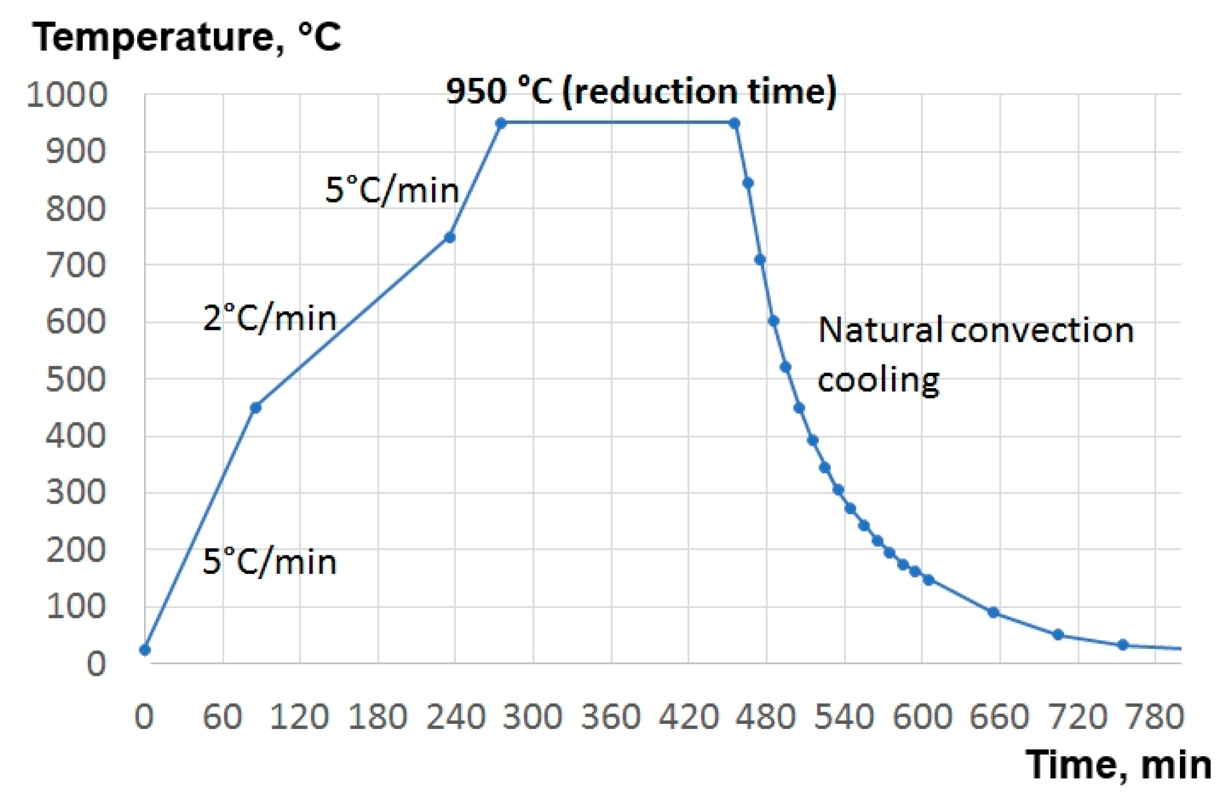
The reduction thermal cycle optimized in the current work is presented in
Figure 5. The heating velocity of 5 °C/min was used up to 450 °C, then the heating velocity was decreased to 2 °C/min until the temperature of 750 °C was reached. In this temperature range, the conversion to MoO
2 takes place. A lower heating ramp was used to minimize the sublimation of MoO
3, induced by local overheating caused by the exothermic reaction. The heating from 750 °C to 950 °C was realized with a 5 °C/min ramp rate. Then, the reduction from MoO
2 to Mo was performed at 950 °C, setting different time intervals for each experiment, as listed in
Table 2. Subsequent cooldown was obtained through natural convection, simply by switching off the furnace. The product was exposed to air only after the system had reached the room temperature.
3.2.1. Reduction of Commercial MoO3
In order to develop the reduction method, commercially available MoO3 powders from Sigma Aldrich were used. The grain size of the powders was <5 µm.
The parameters and the results of the reduction experiments are listed in
Table 2. The first reduction experiment R-1, starting from ~0.6 g of commercial MoO
3, was realized with just 1 h reduction time at 950 °C. According to the results of the analyses (XRD, EDS, and quantification based on the mass of the product), this time was not sufficient to convert all MoO
3 into metallic Mo. Nevertheless, no MoO
3 was detected in the final product by XRD, thus indicating that the first step of the process (Equation (4)) was completed.
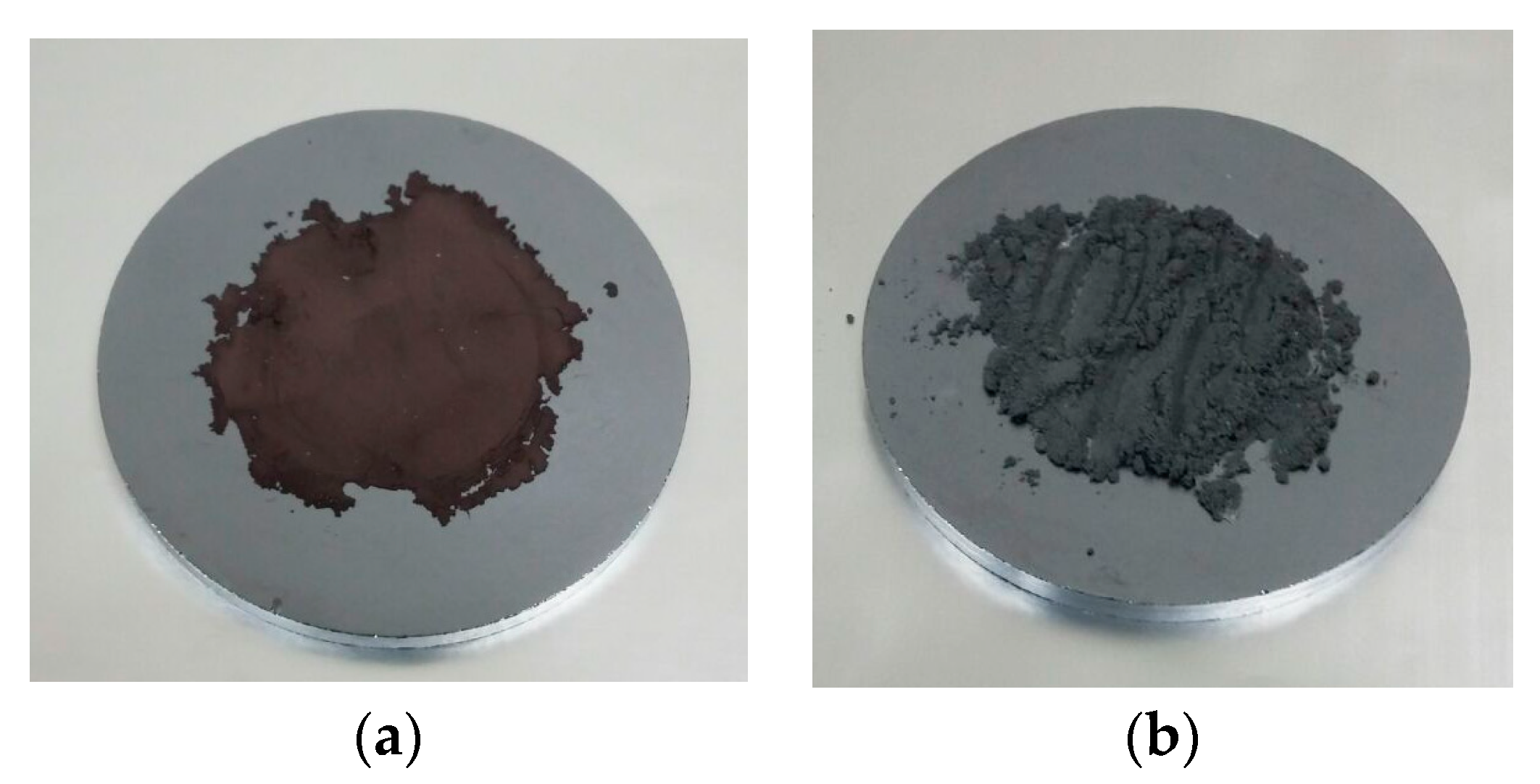
Increasing the reduction time to 6 h in the following experiment R-2 allowed us to obtain more than 95% of Mo metallic starting from ~0.4 g of commercial MoO
3 (
Table 2). According to EDS analysis, still a few % of MoO
2 remained unreduced. The yield of the reaction is ~98%. It should be said, that it was possible to distinguish even visually the products R-1 rich of hygroscopic MoO
2 (see
Figure 6a) and the R-2 product containing almost only metallic Mo powders (
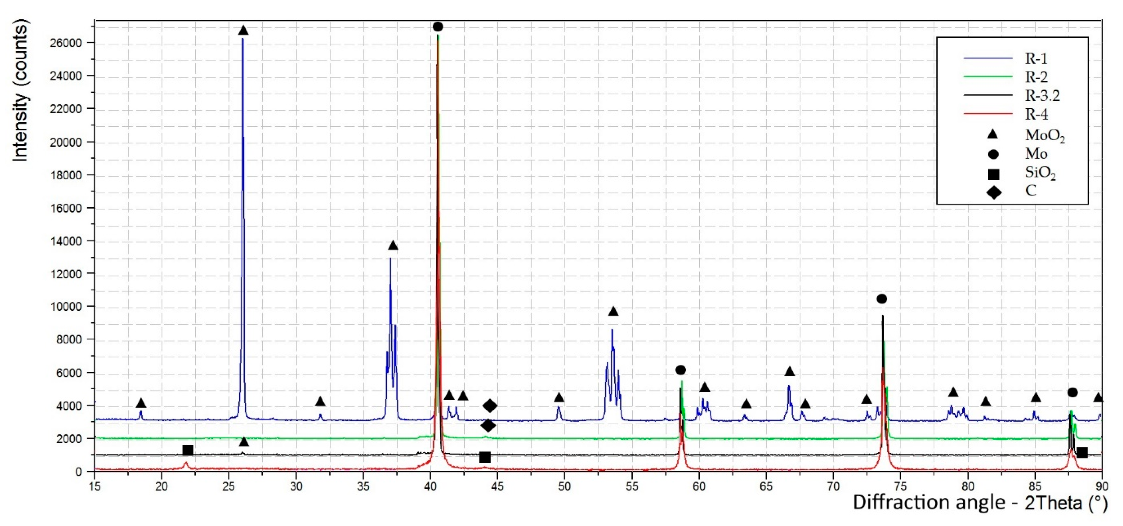
Figure 6b). The XRD spectra, normalized on the intensity of the most intense peaks, obtained from the reduction products are shown in
Figure 7.
The next experiment, with a higher amount of starting MoO
3, was realized in two steps. The R-3.1 during 1.5 h of reduction allowed to get only ~10% of Mo metallic (see
Table 2). In order to convert more than 90% of molybdenum oxide to Mo metallic (
Table 2), the additional 2 h of reduction were required (R-3.2).
Some carbon-based impurities were detected in the product by XRD (see
Figure 7), probably related to previous heating of a graphite crucible in the same furnace. In order to avoid such contamination in the future, the tungsten reactor was mechanically polished.
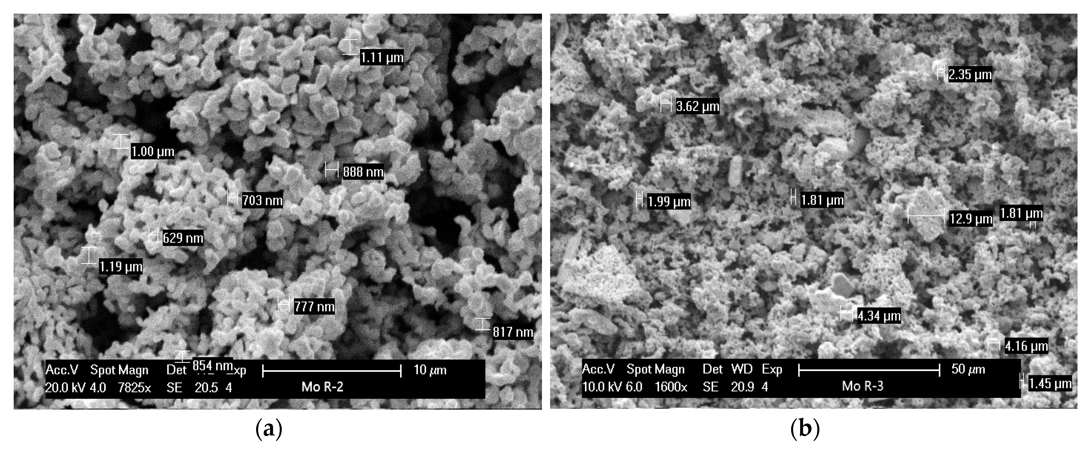
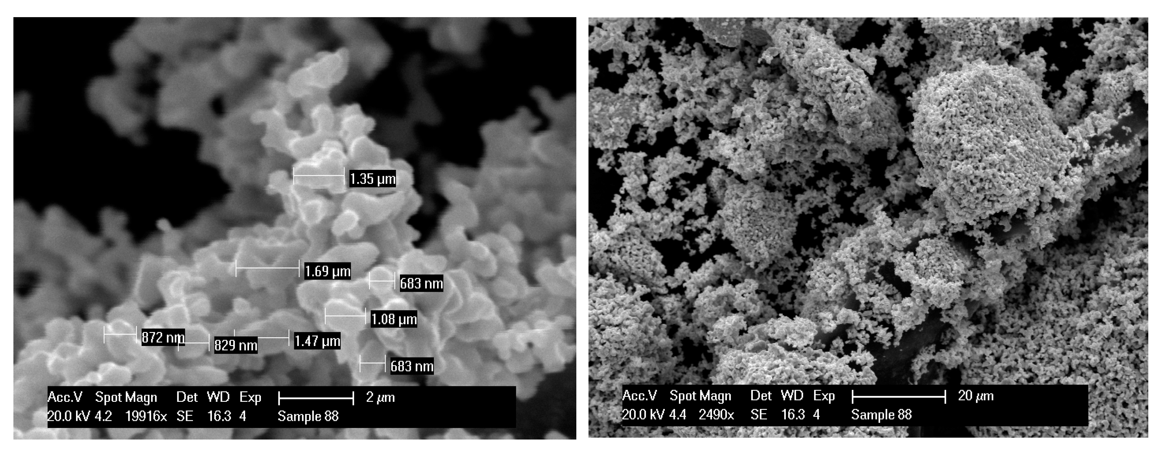
The reduced molybdenum powders are characterized by the grain size of about 1 µm and display nonspherical, slightly irregular shape. The SEM analysis of the products of the reduction R-2 and R-3 is shown in
Figure 8.
3.2.2. Reduction of Recovered MoO3
Several reduction experiments starting from MoO3 recovered from the module Mo-rich waste were realized. It should be taken into account that the precursor (MoO3 from the recovery procedure) was not as pure as the commercial MoO3.
From the analysis of the MoO
3 precursor coming from the recovery procedure, it was evident that it contained the impurities of glass SiO
2 and Na
2SiO
3. From the reduction product analysis (
Table 2), it can be seen that the glass contaminants remained, when MoO
3 was reduced to Mo metallic. Na
2SiO
3 was not detected by XRD, owing to its amorphous nature. The quantification on the basis of reaction stoichiometry calculations is not reliable because of the glass contaminants. Nevertheless, since no MoO
2 was detected by XRD (see
Figure 7), the reduction of MoO
3 could be considered complete.
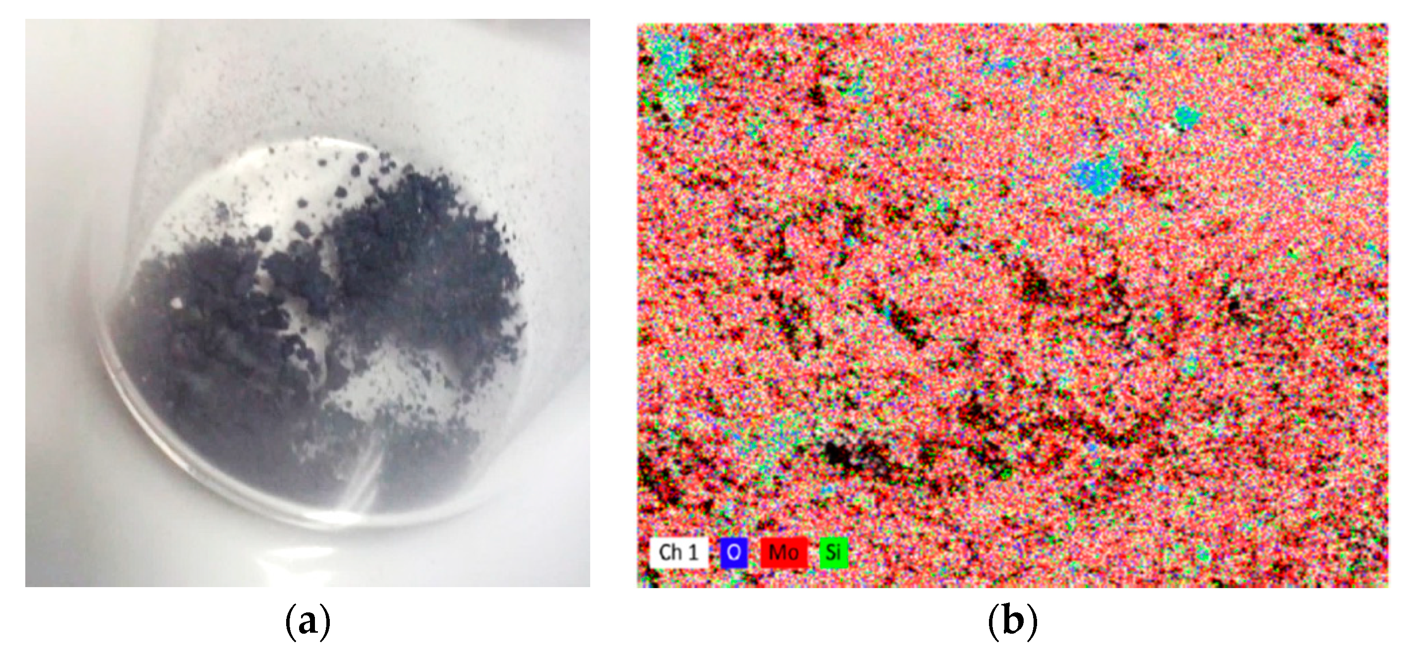
Similarly to what observed in the previous experiment, the SiO
2 impurity coming from the MoO
3 recovered from the separation module waste remained in the product (
Table 2). The appearance of the product was very similar to the R-2 metallic powders (see
Figure 9a). From
Figure 9b, showing the EDS mapping of the reduction product, it can be clearly observed that oxygen is associated with Si to form SiO
2. Moreover, according to EDS elemental analysis, the ratio between the atomic composition of Si and O is 1:2, thus indicating that all oxygen is associated with Si, and there is no excess oxygen to form molybdenum oxide. Therefore, the complete transformation of MoO
3 was demonstrated by the absence of MoO
2 in the product. For both experiments R-4 and R-5, two hours at 950 °C was sufficient to complete the reduction of ~50 mg MoO
3 to Mo metallic.
The developed method allows for the recovery of Mo in metallic form, starting from the Mo-rich “waste” coming from the radiochemical separation module, in two steps with yields of approximately 92% and 98%, respectively, ultimately leading to the overall yield of more than 90%.
3.2.3. Recovered Mo Applicability for Further Cyclotron Target Preparation
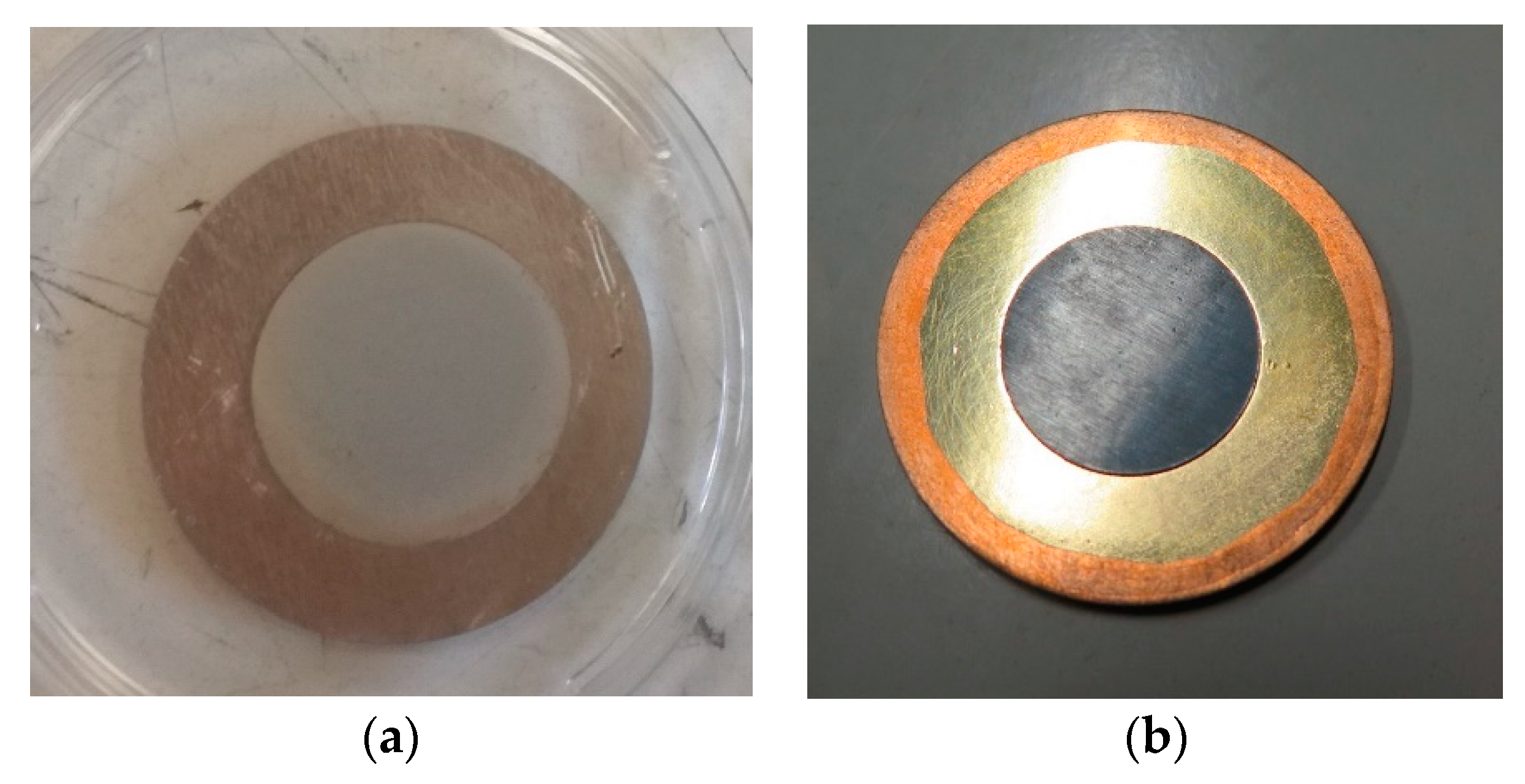
Among the Mo cyclotron solid target preparation methods developed in TECHN-OSP project, the reduced Mo powders have been successfully tested only for electrostatic deposition (HIVIPP) technique. Mo target with ~3-µm thickness deposited by HIVIPP technique onto aluminium backing starting from reduced Mo powders coming from the experiment R-2 is shown in
Figure 10a.
From SEM analysis it was observed that Mo recovered powders (see
Figure 8) had a very similar shape and size with respect to the commercial
100Mo-enriched powders (99.05% isotopic enrichment) of Isoflex (San Francisco, CA, USA), shown in
Figure 11. This ensures the possibility to use recovered powders for the target preparation also using the SPS technique, as the
100Mo-enriched powders of Isoflex have been used (see
Figure 10b).
Since all the Mo recovery tests presented in this work were realized with nonenriched Mo, the further study dedicated to a validation of the proposed methods using enriched Mo powders is essential and is currently in progress.
4. Conclusions
In order to get more attractive from the economic point of view the new, cyclotron-based, 99mTc alternative production route, a procedure to close the loop and recover the costly 100Mo-enriched starting material from the separation module waste under metallic form was developed. The proposed method allowed to perform the recovery of MoO3 with a 92% yield.
For the next recovery steps, a reliable method able to provide the reduction of batches of MoO3 up to 1 g, either from the commercial supplier or using the “working” material coming from the separation module has been developed. Reduction yields up to 98% were achieved with a reduction time no longer than 4 h (+5 h heating). By increasing the reduction time, it may be possible to improve the transformation to metallic Mo or reduce higher amounts of MoO3 in the same reactor. The overall yield of the two steps higher than 90% was achieved.
The recovered Mo powders have been successfully used for preparation of the targets by applying HIVIPP technique. Moreover, the powders display size and shape similar to the commercial 100Mo-enriched powders available from Isoflex, as evidenced by SEM analyses. Therefore, it can be inferred that the SPS technique can also be adopted to produce the Mo targets using recovered powder.

 ,
, 


