A Compact Quick-Release Solid Target System for the TRIUMF TR13 Cyclotron

Life Sciences Division, TRIUMF, Vancouver, BC V6T 2A3, Canada
*
Author to whom correspondence should be addressed.
Instruments 2019, 3(1), 16; https://doi.org/10.3390/instruments3010016
Submission received: 29 December 2018
/
Revised: 4 February 2019
/
Accepted: 7 February 2019
/
Published: 12 February 2019
(This article belongs to the Special Issue Instruments and Methods for Cyclotron Produced Radioisotopes)
Abstract
:A new solid target system for the TRIUMF TR13 cyclotron that can accommodate target discs with a 1-2-mm thickness and a 28-mm diameter has been developed. The target system design is based on a modified clamping mechanism of a KF-40 vacuum connector, and comprises an easy and quick ejection mechanism for the target plate. The new quick-release target system decreases the retrieval time of the irradiated target to less than 1 minute and is expected to reduce the radiation burden to operating staff by a factor of ~10.
1. Introduction
The TRIUMF Life Sciences Division produces positron-emitting radiopharmaceuticals for clinical applications as well as a variety of isotopes for research. The clinical program uses exclusively 11C- and 18F-labeled tracers; however, radiometals such as 68Ga, 64Cu, 44Sc and 89Zr have recently become increasingly important for the development of new chelators and radiolabeled biomolecules [1].
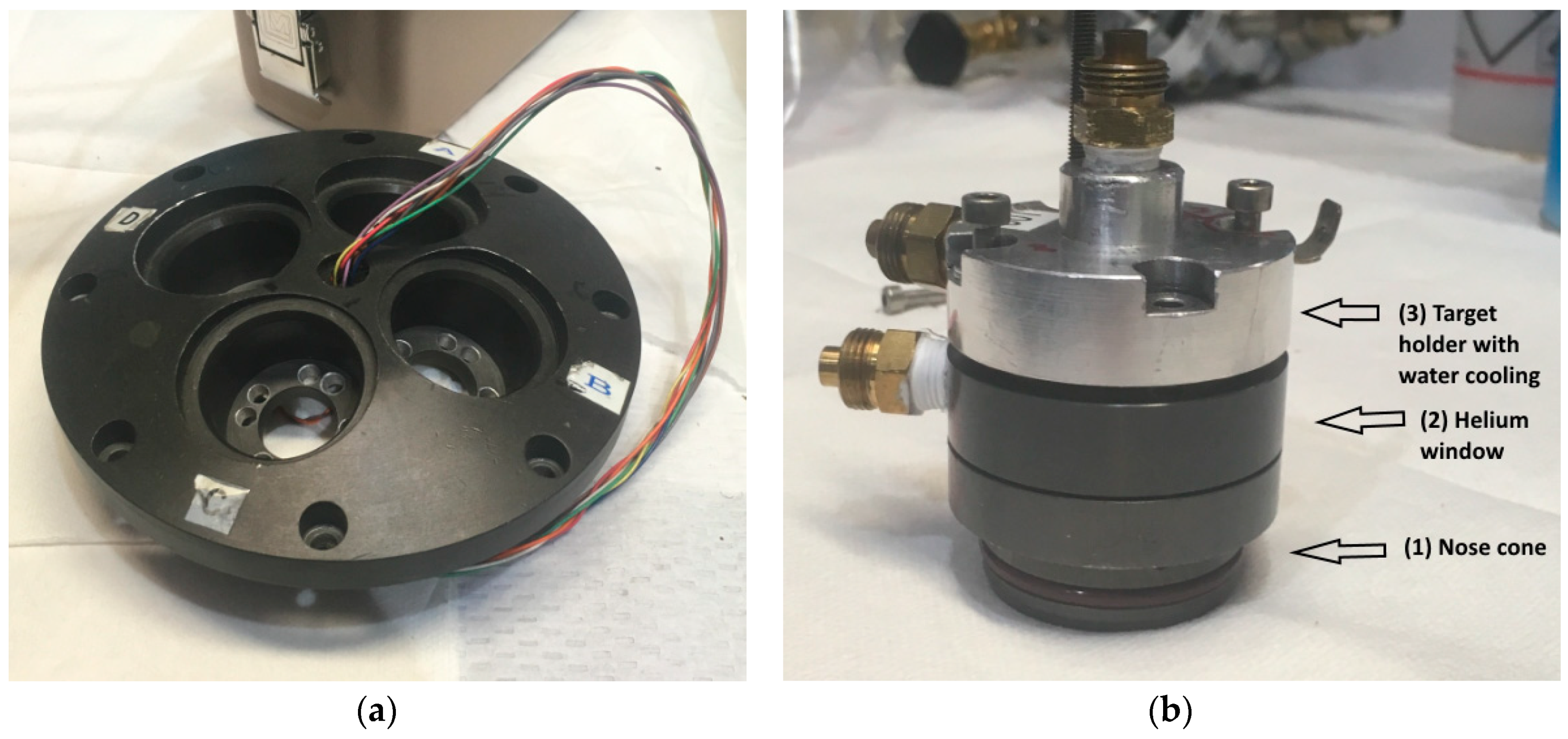
All isotopes for the Life Sciences program are produced on TRIUMF’s TR13 cyclotron [2,3], a self-shielded 13 MeV negative ion accelerator, which is capable of extracting two proton beams of up to 50 µA simultaneously. Irradiations are usually performed at beam currents of up to 25 µA; the produced radioisotopes are used in house or delivered to collaborators in the Vancouver area. The TR13 has two target selectors (one on either beam port), which can accommodate four targets each (Figure 1a). Space on and around the selectors is rather limited, requiring all targets to be of compact design.
Radiometals are commonly produced in solid targets (see for example [4,5,6,7,8]), which typically consist of a backing plate and the actual target material. The target material may be electroplated, sputter-coated or fused onto the backing. The target is then placed into a holder on the beam port of the cyclotron. During irradiation, the target needs to be water-cooled to avoid overheating. Some designs include a thin metal foil that separates the target system from the cyclotron vacuum and prevents the sputtered target material from contaminating the beam port. In order to withstand intense beams, this foil requires cooling, commonly by a helium jet.
For several years, the Life Sciences program has relied on a rather basic solid target system, which consists of three components as illustrated in Figure 1b: (1) a nose cone, compatible with the ports on the TR13 target selector; (2) a helium-cooling assembly, which directs helium jets onto both the entrance foil separating the helium from the cyclotron vacuum and the target plate; and (3) the target holder with water-cooling channels. This system accepts discs with a 35-mm diameter and a 1-mm thickness. The entire assembly is held together concentrically with four screws, which apply sufficient force onto the O-rings located in each component to seal the water and the helium circuits. In order to retrieve the target disc after bombardment, the system needs to be manually removed from the target selector, which requires disconnecting the water- and helium-cooling lines. The target is then transported to a fume hood, where it is completely dismantled, and the irradiated disc is removed. The entire retrieval process takes 8–10 minutes on average, with operators having to spend approximately 5 minutes in close proximity to the highly radioactive targets on the selector.
While this simple system was deemed adequate for the occasional irradiation of a solid target at moderate beam currents, it is not suitable for frequent (daily) use due to the resulting unacceptably high radiation dose to technical staff. TRIUMF’s guidelines limit the maximum daily exposure of Nuclear Energy Workers to 500 µSv and mandate that any radiation burden must be kept as low as reasonably achievable (ALARA principle). Annual whole-body exposure must not exceed 10 mSv.
The issue of handling radioactive target plates could be overcome by installing a remote-controlled target assembly that releases the target into a dedicated transfer system, thus avoiding handling the irradiated target altogether. However, due to space constraints around the TR13 target selector and the lack of penetrations through the cyclotron, shielding the design of an automated system was found to be virtually impossible.
Most of the operator radiation exposure occurs during the disconnecting of the tube fittings on the two water and two helium lines and during the removal of the target assembly from the selector. As such, we developed a new target system that permits the rapid extraction of the irradiated disc in situ while leaving the cooling lines in place.
2. Design
2.1. Functional Description and Specifications
The quick-release solid target system incorporates previously engineered and tested technologies with carefully adapted additions to fulfill the following functional specifications:
- Water-cooling on the back of the target plate to sufficiently cool aluminum, tantalum, silver or rhodium discs at 12.8 MeV, 30 µA proton current;
- Helium-cooling assembly to cool the front entrance foil and the front of the target plate;
- Eliminate the need to disconnect any cooling lines for target retrieval;
- Controlled, reliable unloading of target;
- Assembly must incorporate a current pickup to measure the beam current on target during irradiation;
- System must be able to accommodate 28-mm diameter, 1–2-mm thick discs;
- Design must be compatible with current nose cone, cooling lines, and electrical components.
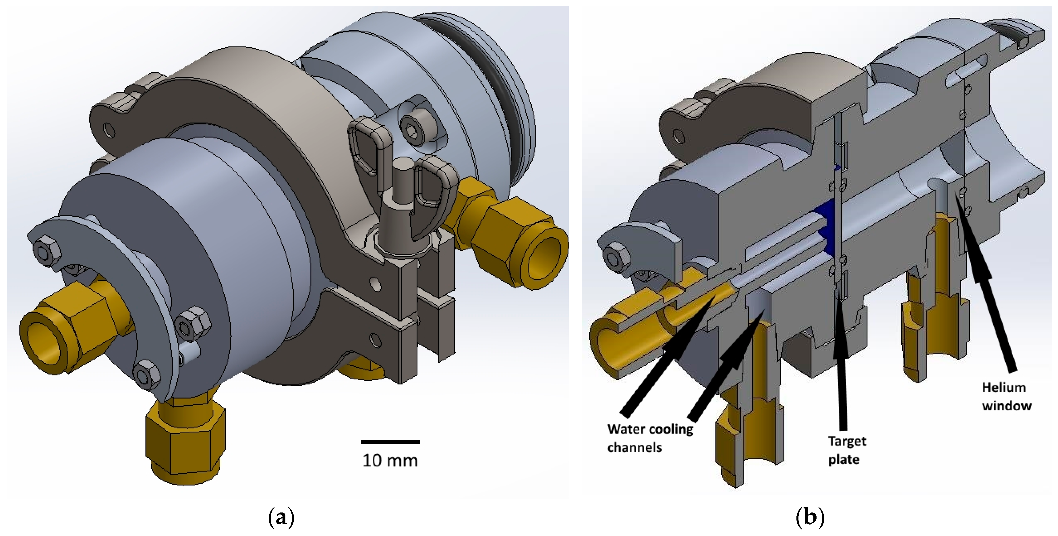
Figure 2 shows three-dimensional renderings of the new system assembly (a) and a longitudinal cross-section (b). The new system is based on a slightly modified KF-40 flange functioning as the quick-release and sealing mechanism. A standard KF clamp is used to connect the preassembled nose cone/helium window component and the water-cooling port, which holds the target disc.
The helium window and water port were designed to maintain similar features and functions as the previous system. The cooling water flows directly onto the center of the back of the target plate, and exits the component parallel to the target plate as before. This allows for the most accessible configuration when the target is mounted onto the target selector. The helium window is compatible with the original nose cone. The helium continues to provide cooling to the front of the target plate, as well as the front entrance foil. Both components use standard tube fittings to maintain compatibility with the existing cooling lines. The water port was designed to incorporate a novel holding and release mechanism that ensures reliable handling of the target plate during removal.
The principle of the operation of the target system is as follows: After the target has been irradiated, the operator enters the target area and releases the KF clamp without removing any cooling lines. At this point, the target plate is still held on the water port by a spring-loaded target holding ring. The target holder is placed over a shielding container; pushing the release mechanism opens a gap between the target holding ring and the target, which allows the plate to drop into the container.
2.2. Detailed Description of Components
2.2.1. Water Port
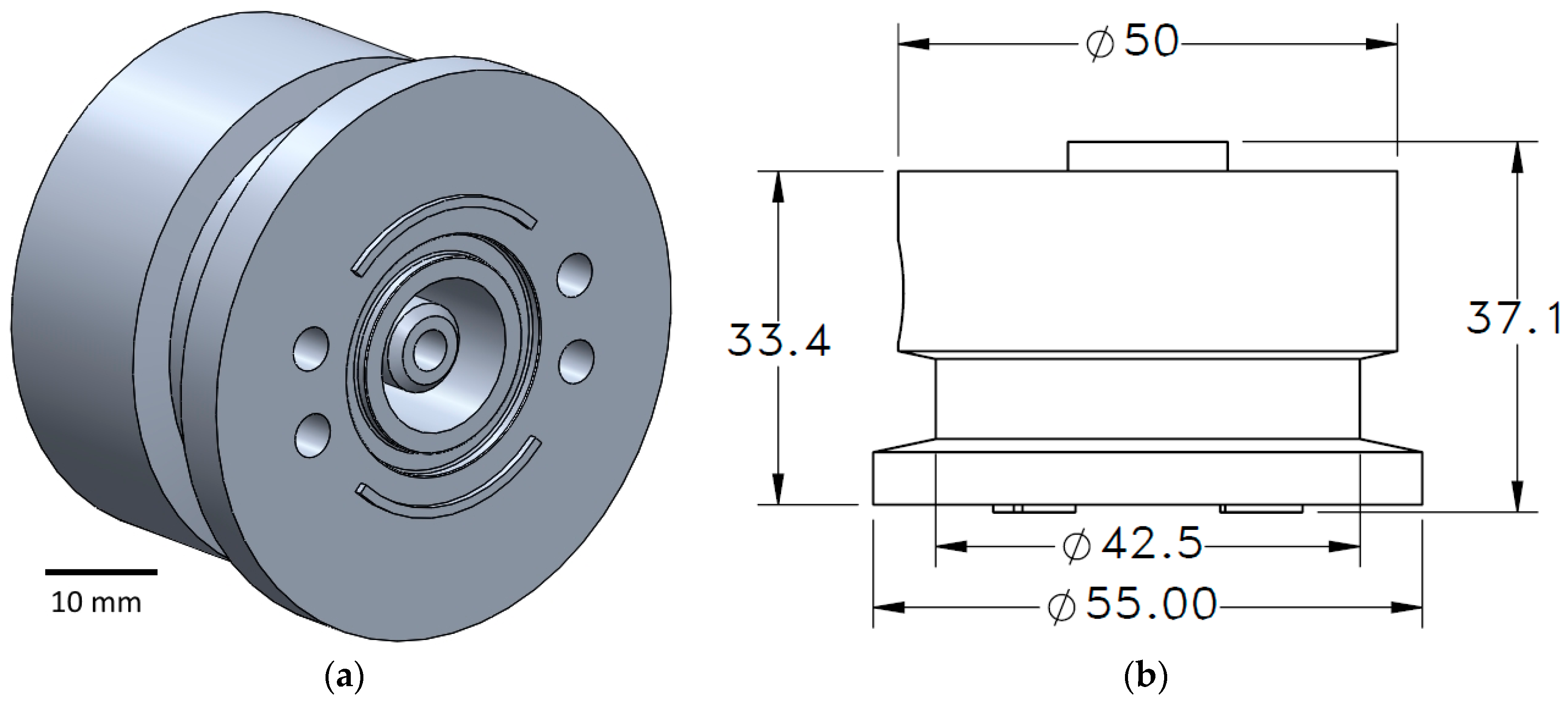
The water port (Figure 3) was designed to perform several important functions in the system. It contains the target holder, the target plate ejection mechanism and the water-cooling channels for the target plate. Four holes lay on a 33-mm diameter reference circle, concentric with the center bore. Each hole is 4.25 mm in diameter and penetrates through the entire body. The holes are used as guides for the release the mechanism’s components. Anchor studs and extension springs are inserted into two of the holes to hold the target plate in place, and release pins are inserted into the other two holes. A 018 O-ring groove surrounds the water channel in the center (018 size O-ring as per AS568 standard: inner diameter 18.77 mm, outer diameter 22.33 mm, cross-section 1.78 mm). This O-ring size was chosen for its inner diameter, which is larger than the given water channel bore but smaller than the given target plate diameter. This difference in size leaves enough room on either side to provide a reliable water seal on the plate face. Raised circular segments with an inner radius of 14.5 mm function as target plate-locating features for consistent centering without hindering plate ejection. These dimensions let the 28-mm diameter target plate sit relatively loose for easy release. The water-cooling line is designed to create an impinging jet that is directed to the center of the target plate. The water disperses radially and exits the component parallel to the target plate.
The various diameters of the component are shown in Figure 3b. The flange diameters of 42.5 and 55 mm are the same as the standard KF-40 flange. The larger diameter fits and is in direct contact with the KF-40 clamp, while the smaller diameter provides enough space for the clamp to surround and compress the flange without obstruction. The 50-mm diameter on the back was chosen to match the previous system size and was deemed appropriate for comfortable manual handling.
The thickness of the component was dimensioned to fit the length of the extension spring and anchor stud of the release mechanism. To assemble the system with these internal components, the water port thickness must be within the range of approximately 30–33.5 mm. An extrusion where the water inlet port is placed extends the nozzle length. Both inlet and outlet use 1/8’’ NPT (national pipe thread) ports to be compatible with current water-cooling lines.
2.2.2. Target Holding Ring and Release Mechanism
The target holding ring, shown in Figure 4, is part of the release mechanism and in direct contact with the target plate to hold it in place. An inner diameter of 26 mm gives 1 mm of material around the ring to hold the outer surface of the target plate. This contact is only designed for positioning and does not need to be helium- or water-tight. Two anchor studs to connect to the springs and two countersunk holes lay on a 33-mm diameter reference circle. This diameter aligns the ring with the water port to integrate the release mechanism. The countersunk holes are made to fit M2 flathead screws. The screw size and style were chosen to maintain a flush surface since the ring, when fully assembled, sits within the KF-40 clamp. The outer diameter of the ring acts as a centering guide for assembling the system; it aligns with the centering grooves of the helium window, as discussed below. The ring is 1 mm thick, leaving additional space between the face of the ring and the surface of the helium window centering groove. This space prevents the contact of the ring with the surface of the helium window, which would obstruct compression of the O-rings by the KF-40 clamp.
The anchor studs were designed in a similar fashion to commercial extension spring anchors. The studs have a hole to latch onto the hook of an extension spring and are thin enough to fit inside the holes in the water port.
The release mechanism comprises the target holding ring, two shafts, and a release plate, facilitating one-handed operation. Figure 4a shows a partially assembled release mechanism and illustrates how the target ring is fastened to both shafts by M2 flathead screws. On the other end of each pin is a 10-mm long M3 outer thread. The release plate is held between two hex nuts. The release plate is shaped as a half circle to clear the water-cooling fitting connected to the back of the water port.
Figure 5a,b are different representations of the release mechanism integrated within the water port. To eject the target, the operator presses on the release plate, forcing the shafts forward. This pushes the target holding ring to the open position, which allows the plate to drop out of the holder. When the system is in its equilibrium position, the extension springs contract, forcing the target holding ring to sit flush with the face of the target plate or, when not loaded, the water port. The purpose of the release mechanism is not to provide a compressive force on the target face to seal against the O-ring. It is designed strictly to hold the target in place during loading and irradiation, and to minimize mishandling during unloading.
2.2.3. Helium Window Assembly
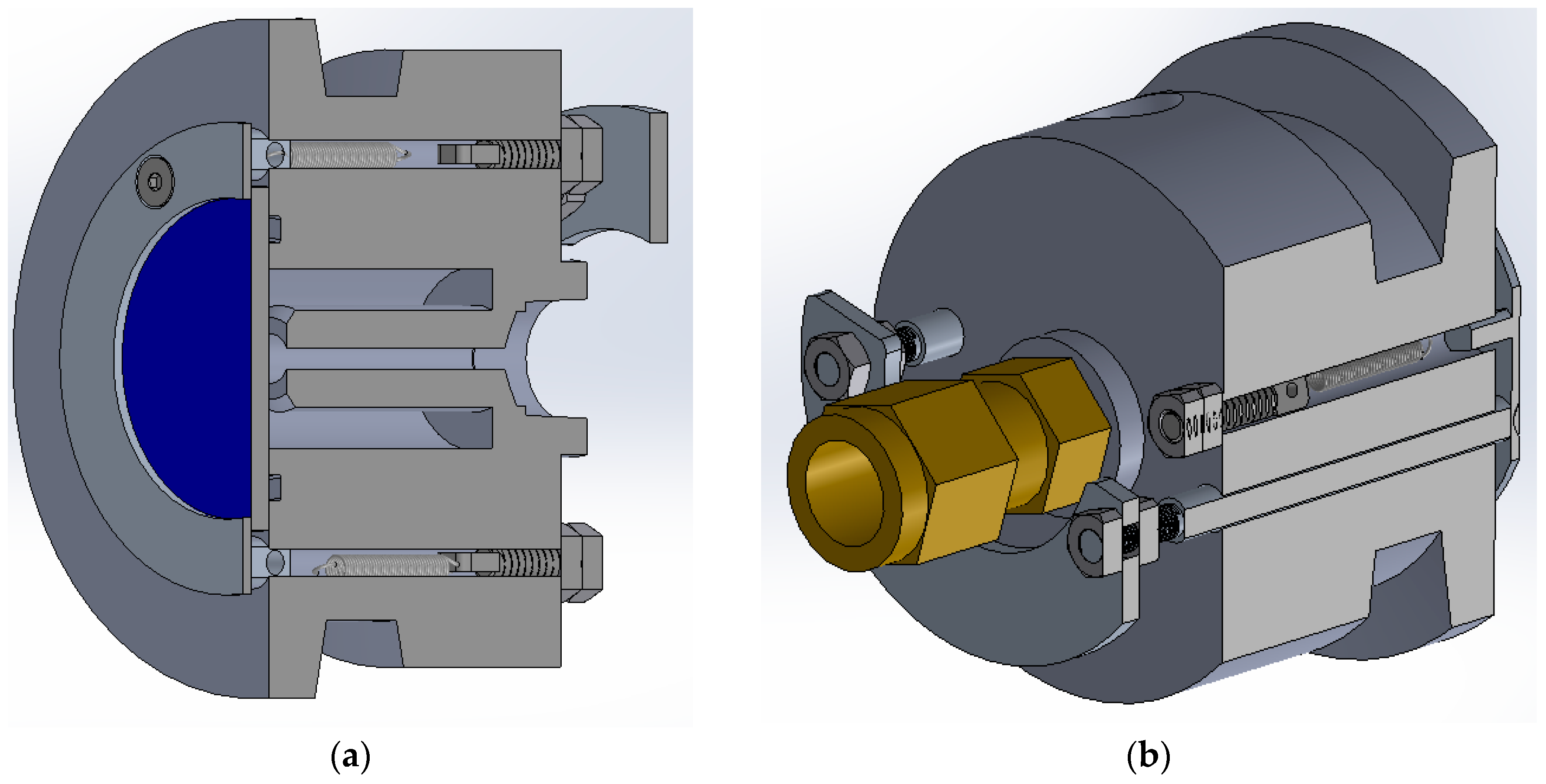
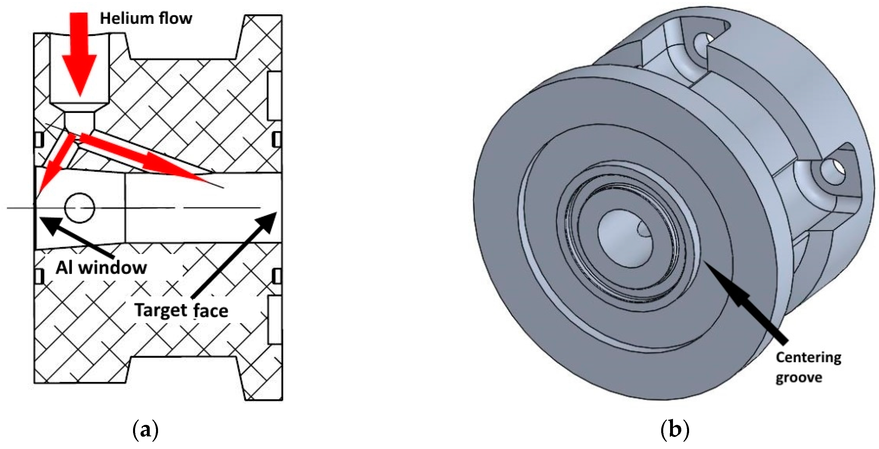
The helium window acts as a separator between the cyclotron and the target plate. The window is fitted with a thin aluminum foil that isolates the internal target assembly components from the cyclotron vacuum. The helium path, as seen in Figure 6a, splits into two directions as it enters the component. One jet is used to cool the aluminum foil; the second jet impinges on the front face of the target plate.
Figure 6b shows the inner face of the helium window. The centering groove is dimensioned to fit the target holding ring in the assembly. To seal the helium window and the water port, both components are pressed together by the KF clamp. The flange of the helium window is dimensioned identically to that of the water port.
The helium window is fastened to the standard TR13 nose cone with four M4 screws in slots. As such, the front part of the assembly does not need to be removed for target retrieval. It is only disassembled for maintenance, i.e., for the replacement of the aluminum foil or the O-rings.
2.2.4. Sealing Mechanism
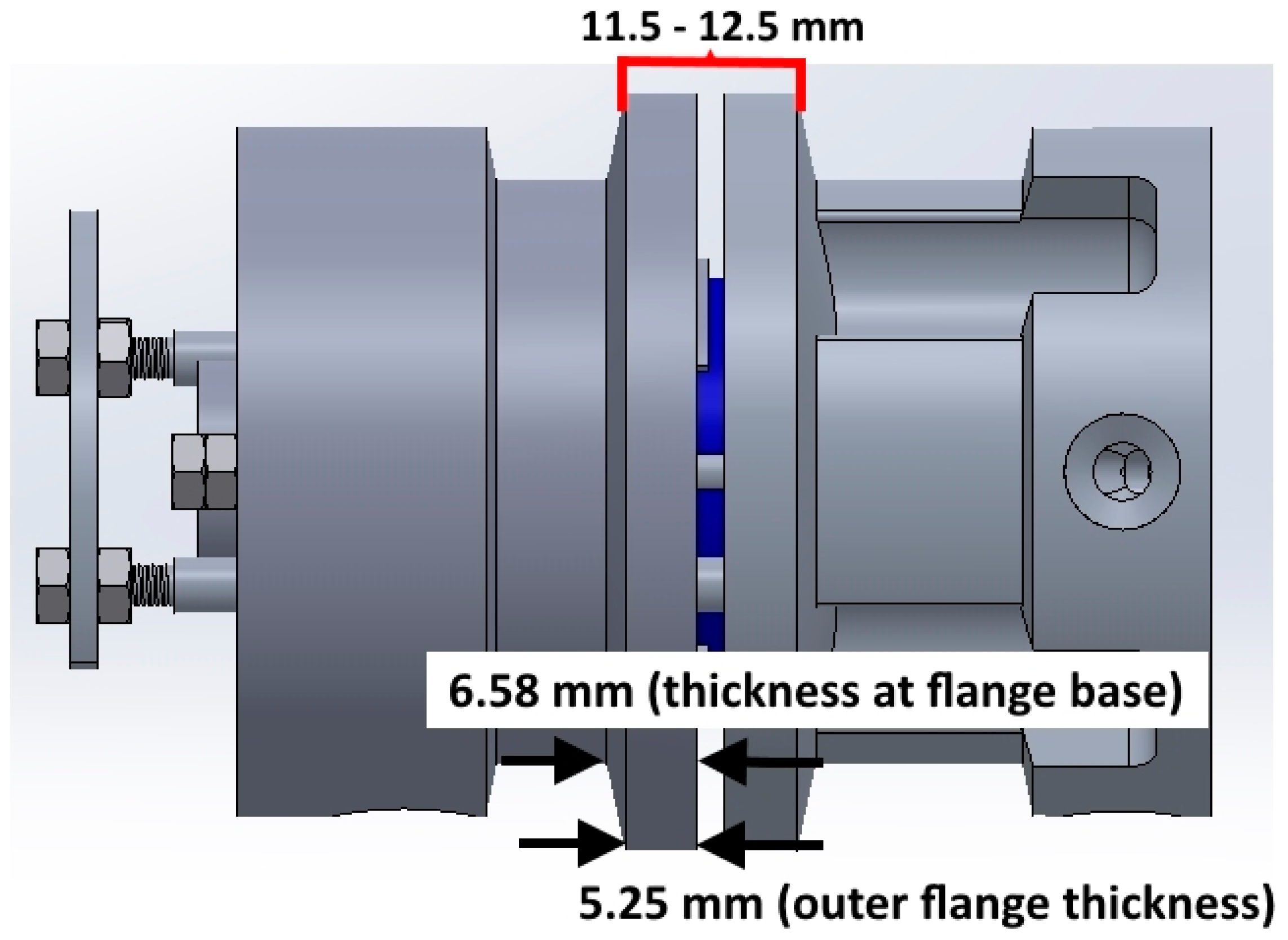
The sealing mechanism uses a KF-40 clamp for primary sealing and quick-release functions. Since a commercial clamp is used for a slightly different function, the adjusted flange dimensions are critical. A standard KF-40 clamp, when assembled with a T-ring and O-ring, has a thickness of 11.75 mm. However, our quick-release system requires a range of 1–2 mm in thickness to accommodate different target plate thicknesses.
Figure 7 shows a rendering of the modified quick-release flange. The thickness of the flange varies from 11.5 mm to 12.5 mm, depending on the thickness of the target plate. This range is asymmetrical about the benchmark of 11.75 mm because the standard clamp is designed with more room on the higher tolerance. Therefore, when using a 1-mm thick target plate, the minimum flange thickness is sufficient to prevent the clamp from bottoming out on the flanges. A 2-mm thick target backing also allows the clamp to close around the flanges.
Each flange of our quick-release system extends outwards from the outermost diameter at a 12-degree angle, which is consistent with the standard KF-40 flange. To achieve the correct dimensions, both the helium window and the water port have outer flange thicknesses of 5.25 mm. This thickness increases to 6.58 mm at the base of each flange.
3. Results
The new quick-release target system was manufactured in house and assembled. The cooling systems were found to be leak-tight. The release mechanism was thoroughly bench-tested in terms of functionality and mechanical robustness and was proven to be very reliable for both 1-mm and 2-mm thick target plates. The target plate can be removed from the target holder in less than one minute.
At the time of this report, the new system was installed on the target selector of the TR13 cyclotron. A series of experiments with varying beam currents will be conducted in the near future to explore its behavior under irradiation conditions.
4. Conclusions
We have developed and manufactured a novel and compact quick-release solid target system based on a modified KF flange assembly. The target system can hold circular plates with thicknesses varying between 1 mm and 2 mm, and provides helium-cooling on the target plate front and water-cooling on the target back. The retrieval of the target plate does not require the removal of the cooling lines. Compared to the currently used basic target holder, the new quick-release system reduces the time required to extract a target plate, from up to 10 minutes to less than 1 minute. It is expected that the radiation exposure to operators will be reduced by a factor of ~10.
Author Contributions
Conceptualization, S.Z. and C.H.; methodology, S.Z., J.K., B.H. and B.C.; formal analysis, B.C. and C.H.; investigation, B.C., S.V., J.K. and S.Z.; resources, S.Z. and C.H.; writing—original draft preparation, B.C., S.Z.; writing, S.Z., B.C., J.K., J.S. and C.H.; visualization, B.C. and S.Z.; supervision, S.Z. and C.H.; project administration, C.H.; funding acquisition, C.H.
Funding
TRIUMF receives federal funding via a contribution agreement with the National Research Council of Canada. This work was supported by the Natural Sciences and Engineering Research Council (NSERC) via the Discovery Grant program (RGPIN-2016-03972).
Acknowledgments
The conceptual design of our system was inspired by a conversation with the cyclotron staff of the University of Wisconsin (Madison), Department of Medical Physics.
Conflicts of Interest
The authors declare no conflict of interest.
References
- Hoehr, C.; Bénard, F.; Buckley, K.; Crawford, J.; Gottberg, A.; Hanemaayer, V.; Kunz, P.; Ladouceur, K.; Radchenko, V.; Ramogida, C.; et al. Medical isotope production at TRIUMF--from imaging to treatment. Phys. Procedia 2017, 90, 200–208. [Google Scholar] [CrossRef]
- Buckley, K.R.; Huser, J.; Jivan, S.; Chun, S.K.; Ruth, T.J. 11C-methane production in small volume, high pressure gas targets. Radiochim. Acta 2000, 88, 201–205. [Google Scholar] [CrossRef]
- Laxdal, R.E.; Altman, A.; Kuo, T. Beam measurements on a small commercial cyclotron. In Proceedings of the EPAC 94, London, UK, 27 June–1 July 1995; pp. 545–547. [Google Scholar]
- Hanemaayer, V.; Benard, F.; Buckley, K.R.; Klug, J.; Kovacs, M.; Leon, C.; Ruth, T.J.; Schaffer, P.; Zeisler, S.K. Solid targets for 99mTc production on medical cyclotrons. J. Radioanal. Nucl. Chem. 2013, 299, 1007–1011. [Google Scholar] [CrossRef]
- Lin, M.; Waligorski, G.J.; Lepera, C.G. Production of curie quantities of 68Ga with a medical cyclotron via the 68Zn(p,n)68Ga reaction. Appl. Radiat. Isot. 2018, 133, 1. [Google Scholar] [CrossRef] [PubMed]
- Zeisler, S.; Limoges, A.; Kumlin, J.; Siikanen, J.; Hoehr, C. Fused zinc target for the production of gallium radioisotopes. Instruments 2019, 3, 10. [Google Scholar] [CrossRef]
- Carzaniga, T.S.; Auger, M.; Braccini, S.; Bunka, M.; Ereditato, A.; Nesteruk, K.P.; Scampoli, P.; Tuerler, A.; van der Meulen, N. Measurement of 43Sc and 44Sc production cross-section with an 18 MeV medical PET cyclotron. Appl. Radiat. Isot. 2017, 129, 96–102. [Google Scholar] [CrossRef] [PubMed]
- Valdovinos, H.F.; Hernandez, R.; Graves, S.; Ellison, P.A.; Barnhart, T.E.; Theuer, C.P.; Engle, J.W.; Cai, W.; Nickles, R.J. Cyclotron production and radiochemical separation of 55Co and 58mCo from 54Fe, 58Ni and 57Fe targets. Appl. Radiat. Isot. 2017, 130, 90–101. [Google Scholar] [CrossRef] [PubMed]
Figure 1.
(a) TR13 four position target selector. (b) Standard TR13 solid target holder.

Figure 2.
(a) New target system assembly in closed position. The water-cooling inlet line is attached to the axially centered fitting on the left; the water outlet is at the bottom left; the beam enters from the top right. (b) Cross-section showing the water-cooling channels, the helium-cooling window, and the target plate.

Figure 3.
(a) Water port (inner face), showing the water-cooling channel in the center, circular segments for target plate centering and the four holes housing the anchor studs with springs and release pins. (b) Water port (side view), dimensions in mm.
Figure 3.
(a) Water port (inner face), showing the water-cooling channel in the center, circular segments for target plate centering and the four holes housing the anchor studs with springs and release pins. (b) Water port (side view), dimensions in mm.

Figure 4.
(a) Partially assembled release mechanism showing the target ring on the left, the release pins connected to the release plate on the right and the springs and anchor studs. (b) Target ring (top view), dimensions in mm.
Figure 4.
(a) Partially assembled release mechanism showing the target ring on the left, the release pins connected to the release plate on the right and the springs and anchor studs. (b) Target ring (top view), dimensions in mm.

Figure 5.
(a) Release mechanism (cross-section). (b) Release mechanism (side view).

Figure 6.
(a) Helium window showing the two channels that guide the helium flow into the center of the aluminum foil on the left and the target plate on the right (cross-section). (b) Helium window inner face.
Figure 6.
(a) Helium window showing the two channels that guide the helium flow into the center of the aluminum foil on the left and the target plate on the right (cross-section). (b) Helium window inner face.

Figure 7.
Quick-release flange system (assembled).

© 2019 by the authors. Licensee MDPI, Basel, Switzerland. This article is an open access article distributed under the terms and conditions of the Creative Commons Attribution (CC BY) license (http://creativecommons.org/licenses/by/4.0/).
Share and Cite
MDPI and ACS Style
Zeisler, S.; Clarke, B.; Kumlin, J.; Hook, B.; Varah, S.; Hoehr, C. A Compact Quick-Release Solid Target System for the TRIUMF TR13 Cyclotron. Instruments 2019, 3, 16. https://doi.org/10.3390/instruments3010016
AMA Style
Zeisler S, Clarke B, Kumlin J, Hook B, Varah S, Hoehr C. A Compact Quick-Release Solid Target System for the TRIUMF TR13 Cyclotron. Instruments. 2019; 3(1):16. https://doi.org/10.3390/instruments3010016
Chicago/Turabian StyleZeisler, Stefan, Benjamin Clarke, Joel Kumlin, Brian Hook, Samuel Varah, and Cornelia Hoehr. 2019. "A Compact Quick-Release Solid Target System for the TRIUMF TR13 Cyclotron" Instruments 3, no. 1: 16. https://doi.org/10.3390/instruments3010016