
Microneedle Manufacture: Assessing Hazards and Control Measures

School of Engineering, Ulster University, Jordanstown BT37 0QB, Northern Ireland, UK
*
Author to whom correspondence should be addressed.
Safety 2017, 3(4), 25; https://doi.org/10.3390/safety3040025
Submission received: 21 March 2017
/
Revised: 3 July 2017
/
Accepted: 24 October 2017
/
Published: 30 October 2017
Abstract
:Transdermal microneedles have captured the attention of researchers in relation to a variety of applications, and silicone-based moulds required to produce these systems are now widely available and can be readily manufactured on the lab bench. There is however some concern over the potential for accidental needlestick injuries and, as with any sharp hazard, the potential for blood-borne pathogen transmission must be considered. This follows from recent governmental concerns over the use of microneedle systems in dermabrasion. Despite the piercing nature of the microneedle patch sharing many similarities with conventional hypodermic needles, there are notable factors that mitigate the risk of contamination. A range of microneedle systems has been prepared using micromoulding techniques, and their puncture capability assessed. A critical assessment of the potential for accidental puncture and the control measures needed to ensure safe utilisation of the patch systems is presented.
1. Introduction
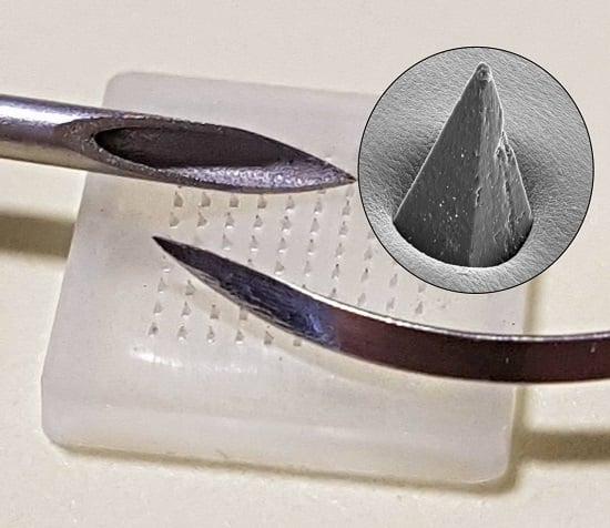
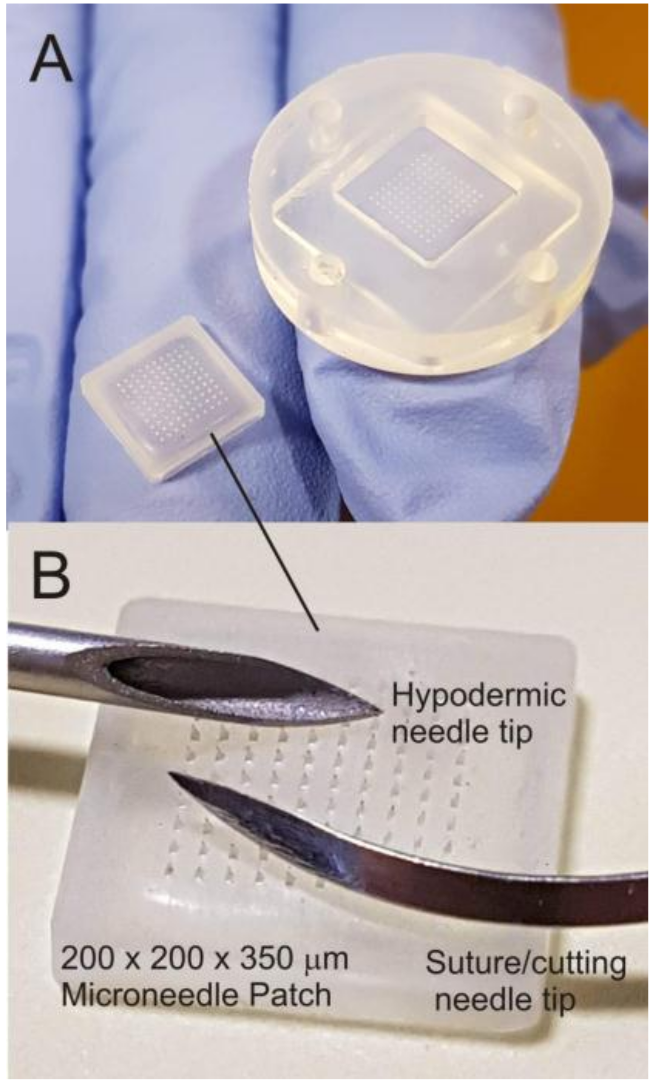
Microneedle patches are increasingly being advocated as a technological step change in drug delivery applications and have been shown to offer a multitude of advantages over conventional syringe-based approaches [1,2,3]. These microneedle (MN) systems typically comprise an array of submillimetre-sized projections (50–900 μm) and, in contrast to conventional hypodermic injections, are sufficiently small that the shallow penetration depth typically fails to trigger the dermal nerve network [3,4]. The near painless puncture of the skin barrier allows the transport of a large variety of drugs and vaccines to the underlying microcirculation, and the success of the general strategy has seen a near exponential rise in publications [2]. As the development of MN patches has continued apace, there has been a trickle-down availability of the technologies required to produce them with silicone moulds, allowing rapid, low-cost production within conventional laboratory environments [1]. An example of a commercial mould and the resulting microneedle array is shown in Figure 1A. The near invisibility of MN tips is often heralded as a major factor in countering needle phobia amongst patients [5,6]; yet these same features can constitute a major issue with regard to their production within the science/engineering laboratory. A comparison between a traditional hypodermic suture and a microneedle tip is highlighted in Figure 1B, and it can be envisaged that the minute dimensions of the MN patch and absence of an easily recognisable and intimidating sharp hazard have the potential to create the false perception amongst students and researchers alike that such devices are benign and could thus be dismissed as possessing little or no danger.
It is critical that the needle element is still recognised as constituting a sharp hazard as its primary function is to puncture the skin barrier enabling access to the underlying tissue. While the intent may be to deliver molecules, it must be noted that, in penetrating the skin, the microneedles will be in contact with the subject’s tissue and microcirculation, with the subsequent extraction of the patch risking the retrieval of blood and/or serous fluid [1,2,3]. As MN systems have become more readily accessible, there is a need for considerable caution beyond conventional chemical risk assessments for those engaged in their production. The latter is highlighted by a health notice issued by Public Health England in relation to the use of dermabrasion microneedles where the possibility of needles transferring blood/serous fluid containing blood borne pathogens (BBP) has been recognised [7]. It is noteworthy that the microneedle rollers consist of needles with similar dimensions to those presently used in drug/vaccine delivery patches. One of the core tenets of MN patch delivery is that the application within a clinical setting is single use and thus minimises the issue of BBP transmission [1,2,3]. However, the production of the MN systems within the laboratory creates a number of issues where the possibility of accidental needlestick through careless handling or disposal of the MN devices is a clear hazard. The core aims of the present investigation have been to investigate the attitudes of science/engineering students towards the safety implications of handling microneedle arrays and to critically assess the ability of control measures to mitigate the risk of accidental puncture.
2. Materials and Methods
2.1. Preparation of Microneedle Arrays
Materials: Polystyrene (PS) (avg. Mw 192,000), cellulose acetate phthalate, acetone (≥99.8%), dichloromethane (DCM, ≥99.8%), and Parafilm M® were obtained from Sigma-Aldrich Company Ltd. (Dorset, UK). Silicone MPatch™ microneedle templates were purchased from Micropoint Technologies Pte Ltd. (CleanTech Loop, Singapore). Bodyguards Blue Nitrile™ gloves with an AQL rating of 1.5 and a minimum typical break force of 9 N were obtained from BM Polyco Ltd. (Enfield, UK). All chemicals purchased were of analytical grade and used without any further purification.
Fabrication: Microneedle templates were cleaned prior to each use by way of sonication in DCM for 300 s and allowed to dry at room temperature. Needle casting involved an initial aliquot of DCM being introduced to a beaker, along with 200 mg of PS beads. A magnetic stirrer was then used to produce a homogeneous PS/DCM mixture, after which the DCM was allowed to evaporate until the desired viscosity was achieved. A small amount of DCM was first pipetted into the template to displace any air present in the mould extremeties. Next, the PS suspension was pipetted into the template, followed by sonication for 300 s to allow the PS suspension to fill the mould completely and to remove any remaining air bubbles. The MNs were visually inspected following sonication and further PS added, if required, to ensure the template was filled. Finally, the MNs were sonicated for a further 300 s and any remaining DCM was allowed to evaporate at room temperature overnight.
Characterisation: The fabricated microneedle arrays were characterised by way of focused ion beam scanning electron microscopy (JSM-6010PLUS/LV InTouchScope™ Analytical SEM, JEOL Ltd., Tokyo, Japan). Microneedles were sputtered under vacuum prior to scanning electronic microscopy using an 80:20 Pd/Au target at 30 mA for 3 min (Emitech K500X Sputter Coater, Quorum Technologies Ltd., East Sussex, UK). An accelerating voltage of 20 kV was used throughout. The resulting Pd coating was applied principally to minimise charging effects during the electron imaging, and it was typically applied post-puncture and had no influence on the mechanical integrity of the needles nor their piercing properties.
2.2. Force Plate Measurements
In order to record force application, a force plate (FP-BTA, Vernier Software & Technology, Beaverton, OR, USA) was employed in conjunction with a Go!Link® single-channel USB interface and accompanying Logger Lite software from the same supplier. The force plate was positioned on a lab bench, adjacent to a chair upon which 12 participants, both male and female, of ages 23–46, were instructed to sit. Once comfortable, the participants were asked to rest on the force plate using their forearm and then using the force plate for support, asked to transfer weight to their hand in order to move from the chair to a standing position. A force-time measurement was recorded three times per participant over a 10 s period in separate data files, with calibration performed prior to each measurement. Finally, data was exported from Logger Lite to Excel 2016 (Microsoft, Redmond, Washington, DC, USA) for statistical analysis and OriginPro 9.0 (OriginLab Corporation, Wellesley Hill , MA, USA) for graphical analysis.
2.3. Glove Puncture Testing
The previously sputter-coated microneedle array was first attached to an aluminium stub using hot melt adhesive. The assembly was wrapped in a section of nitrile glove, which was then placed into and pulled through the SEM sample holder. Once positioned, the glove-wrapped stub was secured into place using grub screws present in the sample holder, just tight enough to ensure that sagging of the nitrile glove did not occur. A section of STAEDTLER Mars® plastic eraser (Nuremberg, Germany) was then pressed upon the glove’s surface to induce microneedle penetration. This was repeated until >90% of needles had visibly penetrated the nitrile glove barrier. Finally, the entire assembly was sputter-coated once again to ensure electrical conductivity.
A pristine microneedle array was affixed to a custom machined compression platen using hot melt adhesive, around which a glove was placed, stretched to size, and fixed using sellotape. A piece of eraser cut to match the dimensions of the microneedle array was fixed onto an opposing platen and aligned prior to compression testing. A custom compression profile was designed for use with a single column universal testing system (Instron® 3344, Buckinghamshire, UK) paired with a 500 N static load cell. Compression limits relating to the force plate scenarios mentioned previously were implemented, i.e., 30 N for resting force, 100 N as an intermediary force, and 170 N for peak force exertion upon standing. Glove samples were then transferred to an SEM sample holder and analysed with an accelerating voltage of 5 kV.
2.4. Survey of Sharp Hazard Perceptions
The perception of sharp hazards and control measures amongst first year undergraduate completing a range of engineering-related programmes was assessed. The study data was extracted from the results of a formative assessment scheduled as part of a compulsory Health and Safety Induction within their Professional Studies module. A total of 88 students from Mechanical Engineering, Mechatronic Engineering, Electrical and Electronic Engineering, Engineering Management, Technology and Design, and Biomedical Engineering were required to participate in an anonymous online quiz managed through BlackBoard Learn™ (Washington, DC, USA). The quiz consisted of multiple choice and short answer questions and is available within the accompanying supplementary information document. It was envisaged that the students would serve as a scientifically and technically literate sample and, given that most would be entering a manufacturing environment, their hazard perception was felt to be of particular relevance to the remit of the present study where the focus is on safety within a production environment. The participation of students in the force plate study and in the online quiz was approved by the Ulster University Faculty of Computing and Engineering Ethics Filter Committee (Ref: 20170911 17.45 and 20170911 17.46)
3. Results
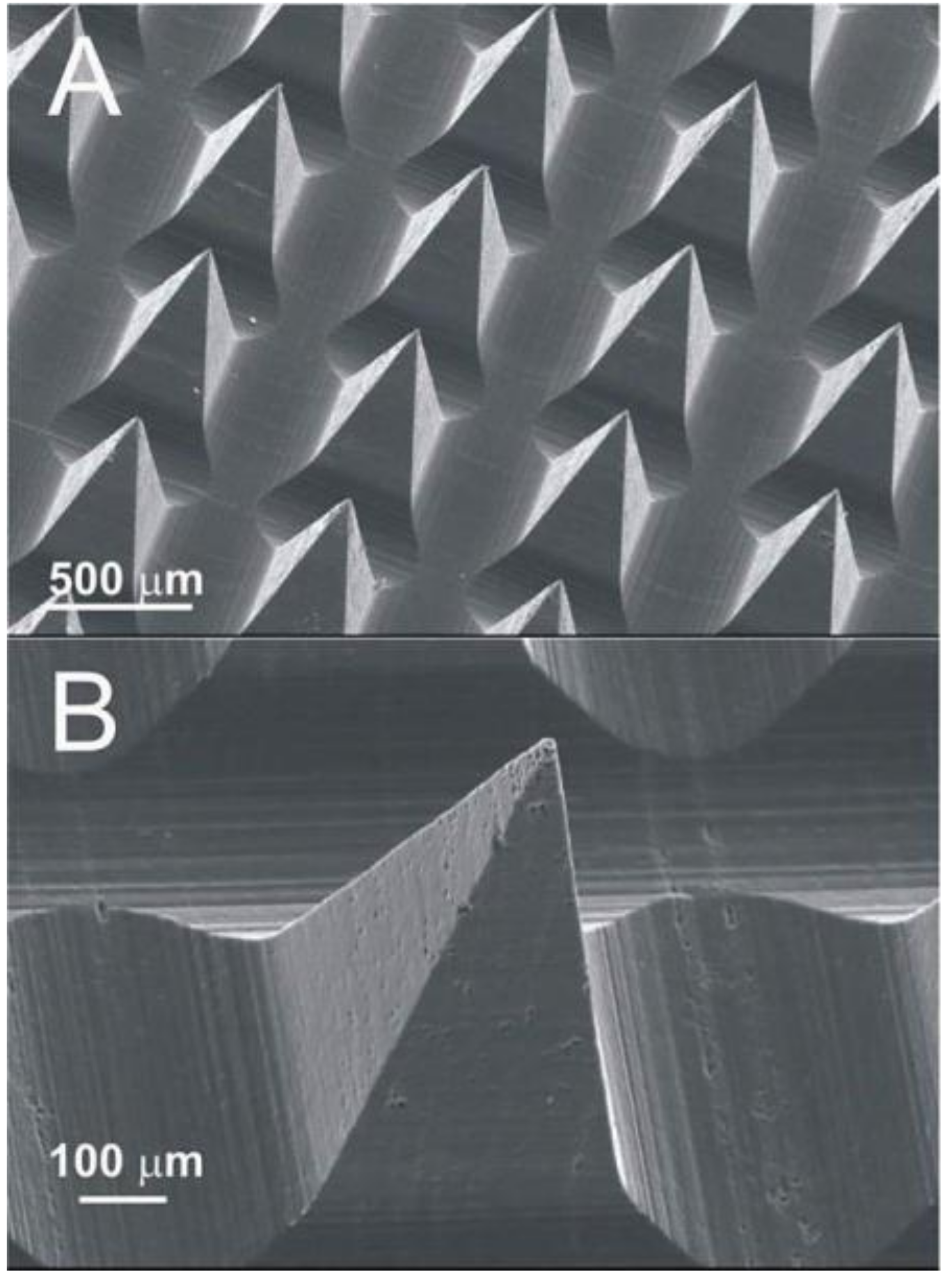
There are five principal classes of microneedle used for drug delivery applications: solid, drug coated solid, hollow, dissolvable, and swellable [1,2,3,8,9,10,11,12,13,14,15,16,17,18,19]. The fabrication of solid MN arrays is procedurally the simplest approach and can be constructed from a variety of conventional and inexpensive polymers such as polystyrene, polycarbonate, and polymethylmethacrylate [8,9,10,11,12]. Such polymers enable the acquisition of mechanically robust arrays that can withstand repeated handling by inexpert users, but the retention of the “sharp” aspect can inadvertently present a needlestick hazard where such devices are carelessly discarded within the workspace. A typical example of a mould-formed solid (non-dissolvable) polymer MN array cast from a solution of polystyrene is shown in Figure 2 and highlights both the field of needles (A) and the sharp tip that arises (B).
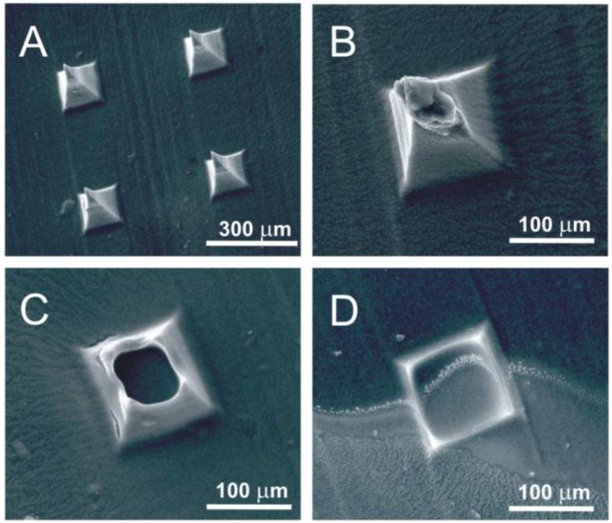
Dissolving MN arrays are a relatively new approach and have many advantages over their non-dissolvable analogues [15,16,17]. They can be produced using the same moulds and procedures used for the fabrication of non-dissolvable systems. An example of a dissolvable MN array formed from the mould casting of cellulose acetate phthalate (CAP) is highlighted in Figure 3. The polymer is commonly used as a pH responsive coating on oral medicines where its function is to protect the encased drug from the rigors of the stomach [20]; the coating degrading in neutral/alkaline environments of the intestine thereupon releasing the therapeutic agent. Similarly, the CAP polymer MN shown in Figure 3 rapidly dissolves when placed in a pH 8 buffer. In the dry state, the needles are mechanically robust and rigid and, as seen in Figure 3A, possess a sharp tip with pronounced piercing capability. It is only when the needles are subjected to an aqueous environment, particularly alkaline conditions, that the needle swells and their mechanical strength is reduced through gradual dissolution (Figure 3B–D).
The dissolvable and swellable systems can be formed from a wide variety of polymer systems with the dissolution rate controlled through the particular formulation employed [15,16,17,18,19]. The scope and intricacies of the latter have been comprehensively reviewed elsewhere [1,2,3] and the compositions exploited in this work are principally used as model systems. There are numerous advantages to the adoption of dissolvable or swellable MNs and, in many respects, they represent the least risk in terms of accidental needlestick and the transmission of BBPs. Upon penetration of the skin, they are effectively self-disarming as their piercing capability is generally lost through the process of dissolution or swelling [15,16,17,18,19].
Irrespective of type, the application of an MN patch is generally described as a pressing sensation rather than a sharp or stabbing response [4], and it is of little surprise that this painless feature has captured the interest of healthcare professionals and patients alike [3,4,5,6]. It has been estimated that thumb pressure alone is sufficient to enable successful MN application in almost 90% of cases [21,22]. This facile application and pain-free administration therefore further compounds the risk where accidental puncture could go relatively unnoticed, and it could be argued that the careless handling or disposal of spent patches could be a greater hazard than a conventional hypodermic needle, which, by its visibility, can immediately induce a degree of caution [5]. When the engineering students were asked to identify the sharp hazards from a picture containing a hypodermic needle, a suture needle, and a microneedle patch, 20% considered the latter to be a sharp hazard. It should be recognised that these concerns go beyond the manufacturing environment, the focus of the present study, and will be relevant to Home Health scenarios where careless disposal and accidental puncture is equally possible. The latter will be significant for children and the elderly where it could be anticipated that their hazard perception of MN patches is liable to be less than that demonstrated by the engineering students—especially given that the students are engaged in science and engineering degree programmes and should be more attuned to recent developments in technology.
Most laboratories possess a heterogeneous population of roles, and, while those directly engaged in MN research may be familiar with the hazards posed by the devices, there will inevitably be many more who are not. It must be remembered that many of the students surveyed would not have come across MN devices prior to the questionnaire, so their response could be considered representative of those non-expert users and, as such, at risk of accidental injury through the reckless placement or discarding of MN patches. While it can be readily accepted that unused or spent solid MN patches are a hazard, there is a question over their ability to accidently puncture skin.
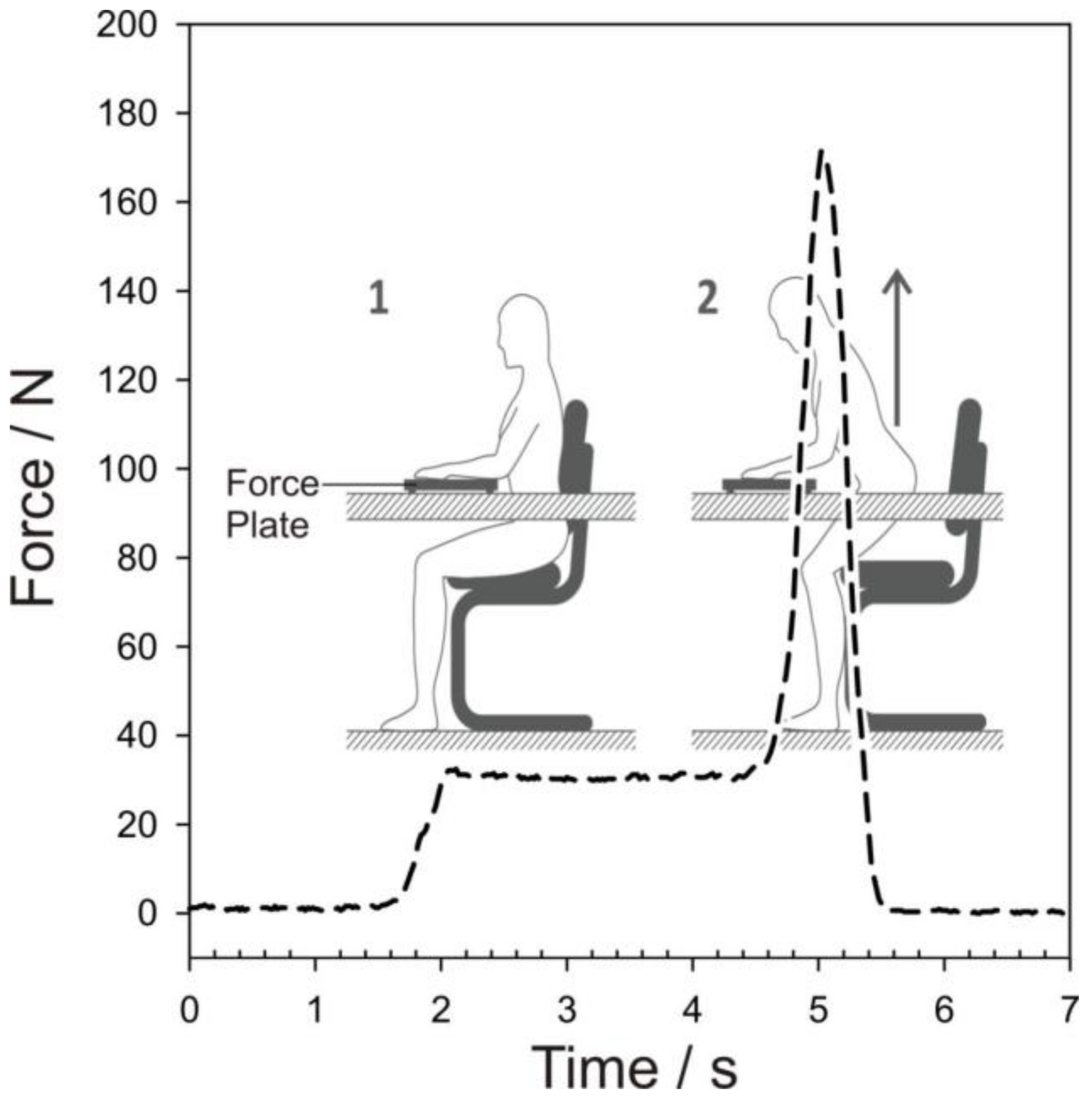
It is generally accepted that thumb pressure alone can facilitate MN puncture, but mechanical applicators capable of delivering a pre-set force are also used as a means of counter any natural variation in the former approach [23]. Accidental MN needlestick injuries will typically occur through the physical depression of the skin onto an upturned MN patch left on a solid substrate/work surface—most likely through the placement of a hand or arm on the latter. The level of risk is therefore dependent on whether the forces exerted on the surface under normal activities are liable to be sufficient to facilitate MN puncture. Two scenarios were investigated in which the subject is in a sitting position and either casually resting their arm on the work surface (1) or using their hand/wrist to raise their body from the seated to standing position (2). The force exerted on the work surface was determined using force plate measurement and a typical force profile for each scenario is highlighted in Figure 4.
The subject was initially in a seated position with no arms on the desk (force plate) surface. Upon resting their arm on the plate—the applied force is increased and plateaus as the movement settles into a natural resting state (Figure 4(1)). As the subject changes to a standing position, the force on the plate increases dramatically as a consequence of hand-wrist leverage being applied to aid their rise from the chair (Figure 4(2)). The magnitude of the various forces will clearly vary from one person to another and this was found in practice where the mean forces for Scenarios 1 and 2 were found to be 45.1 ± 4.3 N and 171.4 ± 18.9 N, respectively, based on a sample of 12 volunteers. The force exerted on the surface through casual placement of the arm alone is greater than that applied by a mechanical applicator, but there are some important caveats to the interpretation of such data. The area in contact with the plate in Scenario 1 will be relatively large, which will significantly dilute the effective pressure applied and it is likely that normal clothing or lab coat would protect the arm and would remove any possibility of skin penetration. The main risk rests in Scenario 2 where wrist leverage is employed. There is a dramatic increase in force that, given the much reduced area of skin in contact with the plate, will necessarily increase the effective pressure on any underlying MN patch. It is important to recognise that, in contrast to the arm, the hand/wrist will be the least protected and more susceptible to MN puncture.
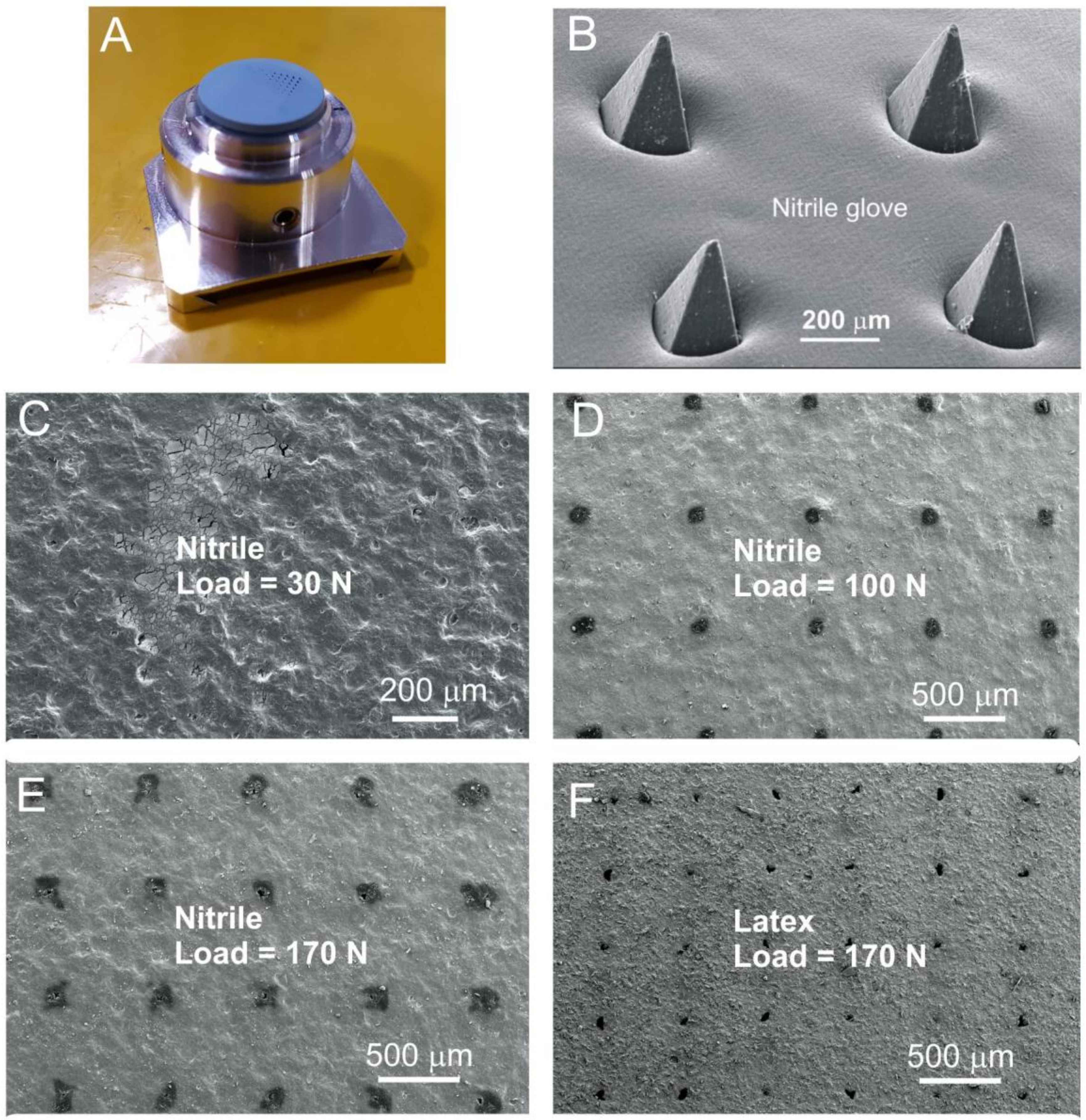
Latex or nitrile gloves are common features within most laboratories and form an intrinsic part of the personal protection equipment and it could be envisaged that these would be the principal physical barrier to preventing MN needlestick injuries in Scenario 2. The protective capability of conventional nitrile and latex gloves (100 μm thick) towards puncture by MN patches was investigated. The MN array was initially mounted in much the same way as would be expected for a discarded patch but, in this case, a SEM stub simulated the work surface as outlined in Section 2.3. The needles were upturned and a section of the glove stretched over the needles (Figure 5A). A small rubber square (serving as the skin substitute) was then applied in a small-scale version of the process indicated in Scenario 2. Subsequent analysis of the SEM stubs revealed that, if the needles are sufficiently long, penetration of the glove is readily achieved. A typical example of the latter is shown in Figure 5B, where an MN patch comprising polystyrene needles of 800 micron length (similar to those detailed in Figure 2) was found to readily puncture the nitrile glove section and would be expected to retain their potential to puncture the skin.
It must be noted that the force applied in this demonstration was unregulated. A more quantitative assessment was conducted using custom compression profiles through which forces of 30 N, 100 N, and 170 N were applied to simulate the scenarios depicted in Figure 4. In this case, the glove section was placed upon the needles rather than being stretched tightly across. After compression, the glove section was removed and analysed using electron microscopy. The resulting micrographs for the nitrile gloves at the various loadings are detailed in Figure 5C–E. A representative sample acquired for a latex glove at 170 N loading is included in Figure 5F for comparison. It can be seen that compression at 30 N failed to pierce the nitrile glove, whereas the 100 N and 170 N tests resulted in puncture for both nitrile and latex. Puncture holes can be seen across the array and, although preliminary in nature, they serve to corroborate the assertion that, in Scenario 2, leverage arising from a person’s wrist/palm when attempting to rise could be a hazard.
Verbaan and coworkers found that the inherent elasticity of the epidermis typically resists puncture; as a consequence, the penetration depth is generally markedly less than the height of the actual microneedle [24]. They highlighted the disparity between the needle capability and potential puncture dynamics with needles with lengths of 300, 550, 700, and 900 microns. The 300 micron needles repeatedly failed to overcome the elastic deformation of the skin barrier and adequately puncture human skin [24]. The dimensions of the needle highlighted in Figure 2B are 800 microns long and, on the basis of Verbaan’s work, sufficiently large that, to unprotected skin, would indeed constitute a puncture hazard [24]. There will be some clear variations from one person to another, and age-related changes in skin will also influence the elasticity of the skin [25,26].
4. Discussion
The level of risk presented by an MN array is dependent on a number of factors, with the nature of the needle structure, the potential BBP concentration, and the adoption and deployment of control measures being among the more critical. Examples of more recent applications of MN are highlighted in Table 1. In general, the moulds that are commercially available enable the pursuit of all bar the hollow structures and the mode of action of the needle is largely dependent on the properties of the polymer used in the casting process [1,2,3]. What is clear from Table 1 is that in most cases the needle height/length is of a magnitude that is capable of puncturing conventional gloves. The consequences of skin puncture are varied and, given the interplay of mechanical and chemical factors within the needles and in relation to the skin, there is a need to consider the possible outcomes.
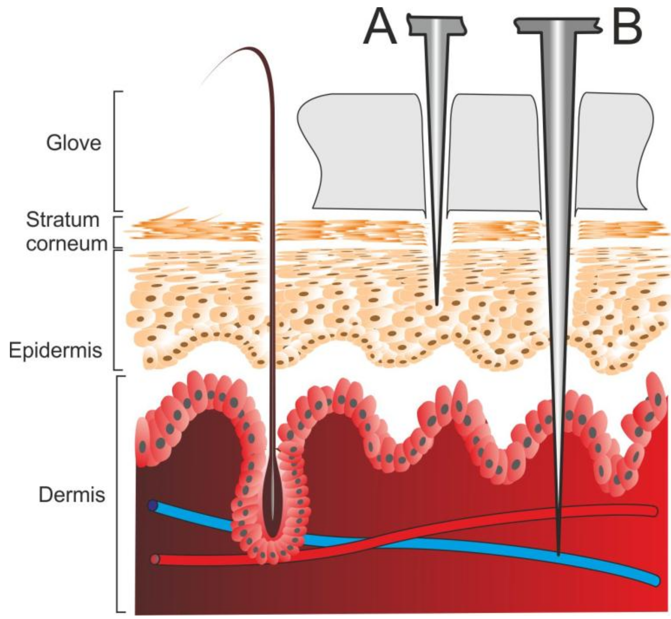
The primary function of the MN is to breach the stratum corneum through the creation of micron-sized channels [1,2,3], as indicated in Figure 6. It would be expected that the small dimensions of the channels result in minimal damage to the skin and there have been many studies, which have found no sustained erythema or irritation following the removal of the MN patch [27]. While the principal intention of the channel is to enable the passage of drugs to the underlying tissue, it is possible that the micro-channels could also serve as highways for the transport of bacteria. Under clinical conditions, good practice would necessitate the preparation of the target area with the use of alcohol/chlorhexidine wipes to remove adventitious species present upon the skin surface and thereby substantially reduce the risk of infection. In the case of manufacturing laboratories, the assumption is that any application to human skin occurs as a result of accident and that there will therefore be no prior treatment. It has been shown that the potential for bacterial infection arising from microneedle applications is considerably lower when compared with conventional injection systems [9,28], and, under non-occlusive conditions, the microchannels would be expected to heal within 2 h of the initial puncture [29]. The situation becomes more ambiguous where there is a failure in the dissolution or removal of a dissolvable/swellable microneedle such that partially dissolved needle fragments continue to bridge the skin barrier [1].
The potential for breakage of solid MNs, especially those composed of a non-degradable material/polymer, is also a concern where shear forces, particularly in relation to needles with a high aspect ratio, can result in fragmentation [30]. It is important to acknowledge that in a significant number of publications relating to MN, the focus is on the mechanism and performance with far weaker exploration of the biocompatibility of the materials. Where fragmentation is concerned, it is possible to expect that small particles will be removed through the normal turnover of the epidermal layers (typically 4 weeks) [31], but there have been reports of granulomas resulting from silicon and glass fragments [32,33]. The latter can be countered through the use of biodegradable materials some of which are highlighted in Table 1.
The most significant hazard relates to the possible transmission of a blood-borne pathogen as indicated in the health warning issued by Public Health England [7]. There is a wealth of literature on the typical contamination risks associated with these viruses within healthcare contexts where needlestick injuries are common [34,35], but the abundance of statistics has no direct translation when considering risk within science/engineering/manufacturing laboratories where there is no routine application to patients. The risks cannot be negated on that basis, however, and could be exacerbated in some aspects in terms of discarded patches where, in contrast to healthcare sectors, there can be an inadequate perception of the risk. There are a number of factors that influence the potential risk of BBP transmission—the depth of penetration, the concentration of virus, the nature of the needle (solid or hollow), and the presence of a glove (single or double) [36,37,38,39]. The stratum corneum is generally regarded as being of the order of 10–20 microns, with the epidermal layer some 100–150 microns [25,26]. While skin deformation upon puncture will generally prevent complete insertion of the microneedle array, it is clear from Table 1 that many of the MNs would have the capability of reaching the dermis and directly accessing the microcirculation as indicated in Figure 6.
It has been shown that the risk associated with the transmission of a BBP through a solid needle (typically a suture needle) is estimated to be tenfold less than a hollow bore with the disparity in risk being attributed to the smaller volume of blood being transported in the former and hence a reduction in the viral load [36,37]. It may be possible to equate an MN with a suture needle, but it is also necessary to make note of the much shallower penetration depth that is permissible through their application. This is highlighted in Figure 6 where increasing the length of the needle can result in deeper penetration with access to the dermis layer increasing the potential for retrieval of blood.
There is clearly a significant difference between conventional hollow bore needles and MN arrays where the dimensions of the former and the dynamics of movement induce greater risk of needlestick. Nevertheless, MNs are designed to puncture skin and thus, it can be envisaged that a glove would present similar challenges. While it is generally regarded within the healthcare sector that gloves cannot prevent these injuries, it was clear from the studies here that the ability of an MN array to puncture a glove is dependent on needle length.
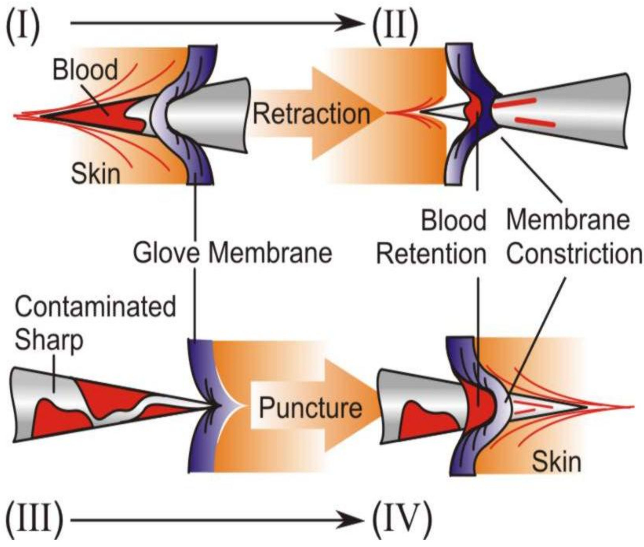
The protection offered by gloves to minimise exposure of skin to chemicals and solvents within a science laboratory is unquestionable, but it is clear from Figure 5 that they do not offer unequivocal resistance to MN penetration. While it is widely accepted that the presence of a glove cannot prevent penetration, they can possess an intrinsic cleaning action that can serve to minimise the transmission of a BBP [36,37,38,39], as indicated in the schematic in Figure 7. It has been shown that, mechanistically, the elasticity of the glove exhibits a ‘‘wiping- like’’ action on the tip of the needle not only as it penetrates through the glove but also as it leaves. Studies employing radiolabeled blood (3H or 125I) have been used to assess the efficacy of gloves (single and double) at removing contamination under simulated needlestick events (hollow bore and suture) [36,37]. It has been estimated that a single glove layer (irrespective of type) can remove between 50 and 86% of blood [36,37,38]. Krikorian and coworkers demonstrated that the amount of transmitted blood is directly dependent on both internal needle diameter and penetration depth with the speed of puncture, the angle of insertion, and the tension experienced by a given part of the glove found to have little effect on the volume transferred [38].
Closer inspection of the electron micrograph detailed in Figure 4 reveals that the elasticity of the nitrile film and the minute dimensions of the needle tip results in the polymer deforming around the MN structure. The direct constrictive/frictional contact of the needle with the film is evident and should therefore facilitate a physical cleansing action. In cases of deep puncture involving either hollow bore or suture needle, there were no additional gains in puncture protection with double gloving [40,41], but that may not be true in the case of MN arrays. The presence of a glove will certainly reduce the degree to which a needle will puncture, but their influence is potentially greater in the context of MNs where the length of the needles is greatly reduced.
The MN array, as mentioned previously, must overcome the elasticity of the glove and the stratum corneum before reaching the tissue. It is important to remember that, unlike the hollow bore puncture, the MN array is limited by the baseplate of the array in how far the needles can travel and therefore the height, or in this case the length, of the needle becomes critical. As the probability of infection after percutaneous injury depends on the volume and viral titer of blood transferred [42], it is clear that minimising MN height, combined with the presence of gloves, could dramatically reduce potential risk.
5. Conclusions
MN technologies have grown in prominence in recent years as their efficacy across a spectrum of therapeutic applications has been demonstrated. The ability to manufacture relatively sophisticated designs through low-cost, commercially available, micro-moulding techniques has enabled once high-end research to be conducted in conventional laboratories. While there are a multitude of benefits to increasing accessibility, it is clear that there is a need for considerable caution in the workspaces in which the microneedle patches are produced and characterised. Most concerns regarding needlestick injuries related to healthcare workers involved in patient contact, but the possibility of accidental injury arising from the careless handling or disposal of microneedle patches is often overlooked. The possibility of blood contamination and transmission needs to be recognised as a hazard, and while the actual risk may be low in comparison to a clinical setting, it cannot be negated where there is a general lab environment with personnel of varying expertise. It was clear from the student survey that the hazard perception on first encountering a microneedle patches is compromised, failing to recognise the device as a sharps hazard, so there is considerable need for greater cautionary education and increased vigilance. Reductions in needle height could be employed to enhance safety, but it must be recognised that some applications demand greater skin penetration, so a blanket restriction is generally impractical. Compliance in the wearing of gloves and improved education are likely to be more effective options that would enable these innovative technologies to be safely pursued.
Acknowledgments
The authors thank the Department of Learning (DEL) Northern Ireland and EC-Lab Ltd. for supporting this work.
Author Contributions
Alexander Martin prepared and characterised the polystyrene microneedles. Aaron McConville conceived and designed the force plate measurements and glove puncture testing. Anna McLister conducted the undergraduate survey. Ashleigh Anderson prepared and characterised the dissolvable microneedles. James Davis oversaw the work and wrote the paper.
Conflicts of Interest
The authors declare no conflict of interest.
References
- Larraneta, E.; Lutton, R.E.M.; Woolfson, A.D.; Donnelly, R.F. Microneedle arrays as transdermal and intradermal drug delivery systems: Materials science, manufacture and commercial development. Mater. Sci. Eng. R Rep. 2016, 104, 1–32. [Google Scholar] [Green Version]
- Cheung, K.; Das, D.B. Microneedles for drug delivery: Trends and progress. Drug Deliv. 2015, 7544, 1–17. [Google Scholar]
- Prausnitz, M.R. Microneedles for transdermal drug delivery. Adv. Drug Deliv. Rev. 2004, 581–587. [Google Scholar] [CrossRef]
- Haq, M.I.; Smith, E.; John, D.N.; Kalavala, M.; Edwards, C.; Anstey, A.; Morrissey, A.; Birchall, J.C. Clinical administration of microneedles: Skin puncture, pain and sensation. Biomed. Microdevices 2009, 11, 35–47. [Google Scholar]
- Birchall, J.C.; Clemo, R.; Anstey, A.; John, D.N. Microneedles in clinical practice-an exploratory study into the opinions of healthcare professionals and the public. Pharm. Res. 2011, 28, 95–106. [Google Scholar]
- Mooney, K.; McElnay, J.C.; Donnelly, R.F. Children’s views on microneedle use as an alternative to blood sampling for patient monitoring. Int. J. Pharm. Pract. 2014, 22, 335–344. [Google Scholar]
- Public Health England. Health Protection Report News; Public Health England: London, UK, 2017; Volume 11, p. 1. Available online: https://www.gov.uk/government/publications/health-protection-report-volume-11-2017 (accessed on 24 January 2017).
- Mccrudden, M.T.C.; Mcalister, E.; Courtenay, A.J.; González-Vázquez, P.; Raj Singh, T.R.; Donnelly, R.F. Microneedle applications in improving skin appearance. Exp. Dermatol. 2015, 24, 561–566. [Google Scholar]
- Donnelly, R.F.; Singh, T.R.R.; Tunney, M.M.; Morrow, D.I.J.; McCarron, P.A.; O’Mahony, C.; Woolfson, A.D. Microneedle arrays allow lower microbial penetration than hypodermic needles in vitro. Pharm. Res. 2009, 26, 2513–2522. [Google Scholar] [CrossRef]
- Luangveera, W.; Jiruedee, S.; Mama, W.; Chiaranairungroj, M.; Pimpin, A.; Palaga, T.; Srituravanich, W. Fabrication and characterization of novel microneedles made of a polystyrene solution. J. Mech. Behav. Biomed. Mater. 2015, 50, 77–81. [Google Scholar] [CrossRef]
- Edens, C.; Collins, M.L.; Ayers, J.; Rota, P.A.; Prausnitz, M.R. Measles vaccination using a microneedle patch. Vaccine 2013, 31, 3403–3409. [Google Scholar]
- Skoog, S.A.; Miller, P.R.; Boehm, R.D.; Sumant, A.V.; Polsky, R.; Narayan, R.J. Nitrogen-incorporated ultrananocrystalline diamond microneedle arrays for electrochemical biosensing. Diam. Relat. Mater. 2015, 54, 39–46. [Google Scholar] [CrossRef]
- Stoeber, B.; Liepmann, D. Arrays of hollow out-of-plane microneedles for drug delivery. J. Microelectromech. Syst. 2005, 14, 472–479. [Google Scholar]
- Vinayakumar, K.B.; Hegde, G.M.; Nayak, M.M.; Dinesh, N.S.; Rajanna, K. Fabrication and characterization of gold coated hollow silicon microneedle array for drug delivery. Microelectron. Eng. 2014, 128, 12–18. [Google Scholar]
- Park, J.H.; Allen, M.G.; Prausnitz, M.R. Polymer microneedles for controlled-release drug delivery. Pharm. Res. 2006, 23, 1008–1019. [Google Scholar]
- Ito, Y.; Murakami, A.; Maeda, T.; Sugioka, N.; Takada, K. Evaluation of self-dissolving needles containing low molecular weight heparin (LMWH) in rats. Int. J. Pharm. 2008, 349, 124–129. [Google Scholar]
- Hirobe, S.; Azukizawa, H.; Matsuo, K.; Zhai, Y.; Quan, Y.S.; Kamiyama, F.; Suzuki, H.; Katayama, I.; Okada, N.; Nakagawa, S. Development and clinical study of a self-dissolving microneedle patch for transcutaneous immunization device. Pharm. Res. 2013, 30, 2664–2674. [Google Scholar]
- Yang, S.Y.; O’Cearbhaill, E.D.; Sisk, G.C.; Park, K.M.; Cho, W.K.; Villiger, M.; Bouma, B.E.; Pomahac, B.; Karp, J.M. A bio-inspired swellable microneedle adhesive for mechanical interlocking with tissue. Nat. Commun. 2013, 4, 1702. [Google Scholar]
- Donnelly, R.F.; McCrudden, M.T.C.; Alkilani, A.Z.; Larrañeta, E.; McAlister, E.; Courtenay, A.J.; Kearney, M.C.; Raj Singh, T.R.; McCarthy, H.O.; Kett, V.L.; et al. Hydrogel-forming microneedles prepared from “super swelling” polymers combined with lyophilised wafers for transdermal drug delivery. PLoS ONE 2014, 9, e111547. [Google Scholar]
- Edgar, K.J. Cellulose esters in drug delivery. Cellulose 2007, 14, 49–64. [Google Scholar] [CrossRef]
- Donnelly, R.F.; Moffatt, K.; Alkilani, A.Z.; Vicente-Pérez, E.M.; Barry, J.; McCrudden, M.T.C.; Woolfson, A.D. Hydrogel-forming microneedle arrays can be effectively inserted in skin by self-application: A pilot study centred on pharmacist intervention and a patient information leaflet. Pharm. Res. 2014, 31, 1989–1999. [Google Scholar] [CrossRef]
- Larrañeta, E.; Lutton, R.E. M.; Brady, A.J.; Vicente-Pérez, E.M.; Woolfson, A.D.; Thakur, R.R.S.; Donnelly, R.F. Microwave-assisted preparation of hydrogel-forming microneedle arrays for transdermal drug delivery applications. Macromol. Mater. Eng. 2015, 300, 586–595. [Google Scholar] [CrossRef] [Green Version]
- Singh, T.R.R.; Dunne, N.J.; Cunningham, E.; Donnelly, R.F. Review of patents on microneedle applicators. Recent Patents Drug Deliv. Formul. 2011, 5, 11–23. [Google Scholar] [CrossRef]
- Verbaan, F.J.; Bal, S.M.; van den Berg, D.J.; Groenink, W.H.H.; Verpoorten, H.; Lüttge, R.; Bouwstra, J.A. Assembled microneedle arrays enhance the transport of compounds varying over a large range of molecular weight across human dermatomed skin. J. Control. Release 2007, 117, 238–245. [Google Scholar]
- Kelchen, M.N.; Holdren, G.O.; Farley, M.J.; Zimmerman, M.B.; Fairley, J.A.; Brogden, N.K. Optimization of impedance spectroscopy techniques for measuring cutaneous micropore formation after microneedle treatment in an elderly population. Pharm. Res. 2014, 31, 3478–3486. [Google Scholar] [CrossRef]
- Laurent, A.; Mistretta, F.; Bottigioli, D.; Dahel, K.; Goujon, C.; Nicolas, J.F.; Hennino, A.; Laurent, P.E. Echographic measurement of skin thickness in adults by high frequency ultrasound to assess the appropriate microneedle length for intradermal delivery of vaccines. Vaccine 2007, 25, 6423–6430. [Google Scholar] [CrossRef]
- Bal, S.M.; Caussin, J.; Pavel, S.; Bouwstra, J.A. In Vivo assessment of safety of microneedle arrays in human skin. Eur. J. Pharm. Sci. 2008, 35, 193–202. [Google Scholar] [CrossRef]
- Wei-Ze, L.; Mei-Rong, H.; Jian-Ping, Z.; Yong-Qiang, Z.; Bao-Hua, H.; Ting, L.; Yong, Z. Super-short solid silicon microneedles for transdermal drug delivery applications. Int. J. Pharm. 2010, 389, 122–129. [Google Scholar] [CrossRef]
- Gupta, J.; Gill, H.S.; Andrews, S.N.; Prausnitz, M.R. Kinetics of skin resealing after insertion of microneedles in human subjects. J. Control. Release 2011, 154, 148–155. [Google Scholar] [CrossRef]
- Park, J.H.; Allen, M.G.; Prausnitz, M.R. Biodegradable polymer microneedles: Fabrication, mechanics and transdermal drug delivery. J. Control. Release 2005, 104, 51–66. [Google Scholar] [CrossRef]
- Baran, R.; Maibach, H. Textbook of Cosmetic Dermatology, 4th ed.; CRC Press: Boca Raton, FL, USA, 2010. [Google Scholar]
- Finley, J.; Knabb, J. Cutaneous Silica Granuloma. Plast. Reconstr. Surg. 1982, 69, 340–343. [Google Scholar]
- Millard, D.R.; Maisels, D.O. Silicon Granuloma of the Skin and Subcutaneous Tissues. Am. J. Surg. 1966, 112, 119–123. [Google Scholar]
- Perry, J.; Jagger, J.; Parker, G.; Phillips, E.K.; Gomaa, A. Disposal of sharps medical waste in the United States: Impact of recommendations and regulations, 1987–2007. Am. J. Infect. Control 2012, 40, 354–358. [Google Scholar] [CrossRef]
- Massachusetts Department of Public Health Occupational Health Surveillance Program. Sharps Injuries among Hospital Workers in Massachusetts, Findings from the Massachusetts Sharps Injury Surveillance System. 2007. Available online: http://www.mass.gov/eohhs/docs/dph/occupational-health/injuries/injuries-hospital-2007.pdf (accessed on 20 January 2017).
- Gerberding, J.L.; Mast, S.T.; Woolwine, J.D. Efficacy of Gloves in Reducing Blood Volumes Transferred during Simulated Needlestick Injury. J. Infect. Dis. 1993, 168, 1589–1592. [Google Scholar] [CrossRef]
- Bennett, N.T.; Howard, R.J. Quantity of Blood Inoculated in a Needlestick Injury from Suture Needles. Obstet. Gynecol. Surv. 1994, 49, 107–110. [Google Scholar]
- Krikorian, R.; Lozach-Perlant, A.; Ferrier-Rembert, A.; Hoerner, P.; Sonntag, P.; Garin, D.; Crance, J.M. Standardization of needlestick injury and evaluation of a novel virus-inhibiting protective glove. J. Hosp. Infect. 2007, 66, 339–345. [Google Scholar] [CrossRef]
- Bricout, F.; Moraillon, A.; Sonntag, P.; Hoerner, P.; Blackwelder, W.; Plotkin, S. Virus-inhibiting surgical glove to reduce the risk of infection by enveloped viruses. J. Med. Virol. 2003, 69, 538–545. [Google Scholar] [CrossRef]
- Tanner, J.; Parkinson, H. Double gloving to reduce surgical cross-infection. Cochrane Database Syst. Rev. 2006, 4. [Google Scholar] [CrossRef]
- Mansouri, M.; Tidley, M.; Sanati, K.A.; Roberts, C. Comparison of blood transmission through latex and nitrile glove materials. Occup. Med. 2010, 60, 205–210. [Google Scholar] [CrossRef]
- Cardo, D.M.; Culver, D.H.; Ciesielski, C.A.; Srivastava, P.U.; Marcus, R.; Abiteboul, D.; Heptonstall, J.; Ippolito, G.; Lot, F.; McKibben, P.S.; et al. A case-control study of HIV seroconversion in health care workers after percutaneous exposure. Centers for Disease Control and Prevention Needlestick Surveillance Group. N. Engl. J. Med. 1997, 337, 1485–1490. [Google Scholar] [CrossRef]
Figure 1.
(A) Micropoint™ 200 × 200 × 350 microneedle (MN) mould template and an example of the resulting polymer cast MN patch. (B) Comparison of sharp hazards.
Figure 1.
(A) Micropoint™ 200 × 200 × 350 microneedle (MN) mould template and an example of the resulting polymer cast MN patch. (B) Comparison of sharp hazards.

Figure 2.
(A) Electron micrograph of a 10 × 10 MN array formed from the solution casting of polystyrene. (B) Individual morphology of a 400 × 400 × 800 micron polystyrene MN.
Figure 2.
(A) Electron micrograph of a 10 × 10 MN array formed from the solution casting of polystyrene. (B) Individual morphology of a 400 × 400 × 800 micron polystyrene MN.

Figure 3.
Progressive dissolution (A–D) of a 200 × 200 × 350 micron MN upon exposure to a pH 8 Britton Robinson buffer ((A) 0 min, (B) 5 min, (C) 10 min, (D) 15 min).
Figure 3.
Progressive dissolution (A–D) of a 200 × 200 × 350 micron MN upon exposure to a pH 8 Britton Robinson buffer ((A) 0 min, (B) 5 min, (C) 10 min, (D) 15 min).

Figure 4.
Variation in applied force as a consequence of resting an arm on a surface (1) and subsequently using hand-wrist leverage to raise the subject from a seated to standing position (2).
Figure 4.
Variation in applied force as a consequence of resting an arm on a surface (1) and subsequently using hand-wrist leverage to raise the subject from a seated to standing position (2).

Figure 5.
Penetration of 400 × 400 × 800 micron polystyrene MNs through conventional nitrile (A–E) or latex (F) gloves (100 μm thick section). (A) SEM stub used for unregulated force puncture and (B) the corresponding micrograph. (C–F) Influence of compression loading post-puncture micrographs of the glove sections.

Figure 6.
Cross-section schematic of the skin interface emphasising the effect of needle length on penetration depth.
Figure 6.
Cross-section schematic of the skin interface emphasising the effect of needle length on penetration depth.

Figure 7.
Influence of glove on the removal of biofluids upon initial penetration of a clean MN (I→II) and upon accidental puncture by a previously contaminated patch (III→IV).
Figure 7.
Influence of glove on the removal of biofluids upon initial penetration of a clean MN (I→II) and upon accidental puncture by a previously contaminated patch (III→IV).


Table 1.
Examples of MN systems.
| Type | Height/μm | Material | Purpose | Ref. |
|---|---|---|---|---|
| Solid | 130 to 1500 | Stainless Steel | Treatment of skin imperfections such as minor scars and wrinkles | [8] |
| Solid | 2802 | Si/Ti/Pt | Determining antimicrobial properties | [9] |
| Solid | 1200 | Polystyrene | Strength testing | [10] |
| Coated | 750 | Stainless Steel, coated with live-attenuated measles vaccine | Measles Vaccine | [11] |
| Coated | 340 | Nitrogen-incorporated ultra nanocrystalline diamond titanium alloy | Biosensing applications | [12] |
| Hollow | 200 | Silicon | Nicotine derivatives Influenza vaccine | [13] |
| Hollow | 300 | Gold coated, hollow silicon Microneedles | Drug delivery | [14] |
| Dissolving | 600 750 | Carboxymethylcellulose | Insulin/Sulforhodamine B Lidocaine | [15] |
| Dissolving | 1520 | Chondroitin sulphate | Heparin Erythropoietin | [16] |
| Dissolving | Various | Sodium hyaluronate and hydrolysed collagen/dextran/povidone | Vaccine | [17] |
| Swellable | 700 | Polystyrene/Poly Acrylic Acid | Anti-scarring agents/antibiotics | [18] |
| Swellable | 600 | Gantrez AN-139 and Polyethylene glycol, | Drug delivery | [19] |
© 2017 by the authors. Licensee MDPI, Basel, Switzerland. This article is an open access article distributed under the terms and conditions of the Creative Commons Attribution (CC BY) license (http://creativecommons.org/licenses/by/4.0/).
Share and Cite
MDPI and ACS Style
Martin, A.; McConville, A.; Anderson, A.; McLister, A.; Davis, J. Microneedle Manufacture: Assessing Hazards and Control Measures. Safety 2017, 3, 25. https://doi.org/10.3390/safety3040025
AMA Style
Martin A, McConville A, Anderson A, McLister A, Davis J. Microneedle Manufacture: Assessing Hazards and Control Measures. Safety. 2017; 3(4):25. https://doi.org/10.3390/safety3040025
Chicago/Turabian StyleMartin, Alexander, Aaron McConville, Ashleigh Anderson, Anna McLister, and James Davis. 2017. "Microneedle Manufacture: Assessing Hazards and Control Measures" Safety 3, no. 4: 25. https://doi.org/10.3390/safety3040025
Note that from the first issue of 2016, this journal uses article numbers instead of page numbers. See further details here.