Preparation of MgO-Templated N-Doped Mesoporous Carbons from Polyvinylpyrrolidone: Effect of Heating Temperature on Pore Size Distribution

Department of Applied Chemistry and Bioscience, Faculty of Science and Technology, Chitose Institute of Science and Technology, Bibi, Chitose 066-8655, Japan
*
Author to whom correspondence should be addressed.
C 2019, 5(2), 15; https://doi.org/10.3390/c5020015
Submission received: 7 March 2019
/
Revised: 29 March 2019
/
Accepted: 30 March 2019
/
Published: 2 April 2019
(This article belongs to the Special Issue Nitrogen-Doped Carbon Materials)
Abstract
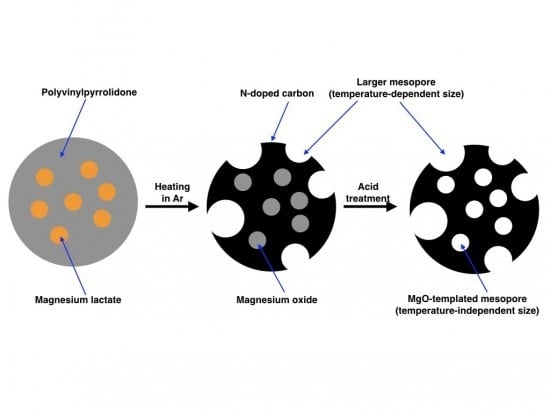
:Magnesium oxide (MgO)-templated nitrogen (N)-doped mesoporous carbons were prepared by using polyvinylpyrrolidone (PVP) as a raw material and magnesium lactate (Mglac) as a precursor for the MgO template to examine the influence of heating temperature and MgO precursor (magnesium acetate was used in similar previous studies) on the pore size and nitrogen content. The MgO-templated carbon was obtained by heating the PVP/Mglac mixture in an inert atmosphere followed by an acid treatment for MgO removal. The mesopore size of the carbons was approximately 4 nm regardless of heating temperature, corresponding to the crystallite size of the MgO template estimated via X-ray diffraction. This indicates that the mesopore of approximately 4 nm was generated using the MgO template. However, larger pores were also found to exist. This result indicates that the larger pores generated through processes other than the MgO templating, likely the thermal decomposition of PVP, are contained in the templated carbon. The volume of the larger pores and the specific surface area increased with increasing heating temperature. The nitrogen content of the carbon decreased as the heating temperature was increased, but it was found to be irrelevant to the MgO precursor.
1. Introduction
Nitrogen (N)-doped carbon has been extensively studied from various technological viewpoints [1,2,3,4,5,6,7,8,9,10,11,12,13,14,15,16,17,18,19,20]. In particular, N-doped carbons are expected to be applied as electrode materials for electric double layer capacitors (EDLC) operated with aqueous electrolytes. Doping carbon materials with N has been known to increase their electrostatic capacitance. This effect is usually explained by the introduction of surface functional groups containing nitrogen; such functional groups act as sites for electron-donating and accepting (redox) reactions [14]. Although these redox reactions contribute to the increased electrostatic capacitance, the improvement of pore wettability is another important effect of N-doping that can lead to increased capacitance. In order to increase pore wettability, in addition to N-doping, the introduction of mesopores (pore with diameters in the range of 2–50 nm) is an effective way to overcome the surface tension of water. The combined effects of N-doping and mesopore introduction are expected to improve the hydrophilicity of carbon materials and consequently increase their electric capacitance.
A template method employing magnesium oxide (MgO) is known to be a useful technique for making mesoporous carbons with controlled pore sizes [21,22,23,24,25,26,27,28]. For example, polyvinylpyrrolidone (PVP), polyacrylamide, and trimethylolmelamine have been used as raw materials for N-doped carbon and magnesium acetate has been used to create MgO template [5,27]. Heating the mixture in an inert atmosphere produced N-doped carbon mixed with crystalline MgO, which was removed by washing with dilute sulfuric acid to obtain the mesoporous N-doped carbon. The mesopore size of the resultant N-doped carbon was smaller than 6 nm for carbons derived from PVP and trimethylolmelamine, while the pore size distribution was centered around 4 nm for carbon derived from polyacrylamide [5]. This means that the pore size distribution depends on what carbon source is used. MgO-templated carbons derived from polyvinyl alcohol (PVA) (which does not contain nitrogen) have also been prepared using several MgO sources: magnesium acetate, citrate, and gluconate [21,22,25,26,27]. The results showed that the pore size also depended on the MgO source. Additionally, the nitrogen content in N-doped carbon has been known to depend on the heating temperature. Generally, the nitrogen content in the product decreases if the precursor is heated to a relatively high temperature. To control the electric properties of MgO-templated N-doped mesoporous carbons, it is necessary to manipulate both their pore size distribution and nitrogen content to fabricate materials with appropriate structures.
In this work, we employed PVP as the raw material for N-doped carbon and magnesium lactate (Mglac) as the precursor of MgO and prepared N-doped mesoporous carbon by heating a PVP/Mglac mixture at 800–1000 °C followed by acid treatment. Mglac is a water-soluble magnesium carboxylate, so it was able to be homogeneously mixed with PVP in an aqueous solution. Additionally, Mglac is non-toxic and used as an ingredient in mineral supplements, skin moisturizers, and cosmetics. Mg lactate has hence been commercially available and can be used as an environmentally friendly chemical. The aim of this work is to elucidate the effects of heating temperature and MgO source on the pore size distribution and nitrogen content. Previously, it was reported that the specific surface area of MgO-templated carbon derived from the mixture of PVP and magnesium acetate increased with increasing heating temperature [5]. By raising the heating temperature from 700 °C to 1000 °C, the specific surface area of the resultant carbon increased from around 600 m2·g−1 to around 1500 m2·g−1 in the case of a PVP/MgO (MgO generated from acetate) mixture with a 1:1 weight ratio. This increase is strongly related to changes in pore size distribution induced by the heating temperature change. However, the mechanism of the specific surface area change has not been determined because the size ranges of the MgO-templated pores and those generated by the thermal decomposition of PVP have not been clearly distinguished in previous reports. This is the main subject of this study.
In addition, this study was performed to elucidate the relationship between pore structure and heating temperature. As described above, the pore size distribution has been known to also depend on the MgO source in the case of PVA/MgO mixtures. However, the influence of the MgO source on the pore size of N-doped carbon derived from PVP has not been examined; only magnesium acetate has been used to prepare MgO-templated N-doped carbon from PVP. Pore size control using different MgO precursors has not been examined for PVP-derived carbons. Mglac was used in this work as another example of a magnesium source. The pore size distribution of the N-doped carbon obtained was compared to that of carbon derived from PVP/magnesium acetate mixtures to determine the underlying mechanism of the differences in pore sizes obtained with different MgO precursors.
2. Materials and Methods
Materials used were PVP K-30 (average molecular weight 40,000) provided by Junsei Chemicals, Tokyo, Japan and Mglac trihydrate (stated purity ≥98.0%) provided by Kishida Chemicals, Osaka, Japan. PVP (10 g) and Mglac trihydrate (10 g) were separately added to 100 mL of water and then stirred until they were completely dissolved at 30 °C and 100 °C, respectively. The solutions were mixed and successively stirred at 100 °C for 30 min. Water in the mixture was vaporized at 65 °C for one day to leave behind a PVP/Mglac mixture.
This mixture was then divided into portions of about 3 g. The divided mixture was put into an electric tubular furnace (FT-01 VAC-WM, Full-tech, Yao, Japan), and the air in the tube was evacuated. Then argon gas was introduced to the tube (flow rate: 60 mL·min−1). The mixture was heated at 800–1000 °C for two hours in argon flow. The temperature in the furnace was increased from room temperature to the heating temperature for 10 min. This treatment resulted in carbonization of the mixture to give the N-doped carbon/MgO product. The product was cooled to room temperature and immersed in 200 mL of 1 mol/L sulfuric acid, sonicated for 10 min, stirred for two hours, and stored for two days to remove MgO from the mixed product. The obtained N-doped carbon was filtered, washed with water, and dried in vacuum at room temperature.
The crystal structure of the products was observed by means of X-ray diffractometry (XRD) (RINT2000, Rigaku, Tokyo, Japan) using CuKα radiation and a scan rate of 2°/min. Elemental analysis of the products was carried out by X-ray photoelectron spectroscopy (XPS) (JPS-9200, JEOL, Tokyo, Japan) using a MgKα X-ray source. Molar percentages of nitrogen, carbon, oxygen, and magnesium in the products were calculated based on narrow scan spectra for the elements (number of accumulated scans: 10). Nitrogen gas adsorption measurements were carried out by using an automated sorption analyzer (Autosorb, Quantachrome Instruments, Boynton Beach, FL, USA). Both adsorption and desorption experiments were performed at −196 °C using liquid nitrogen and the isotherms were obtained. The specific surface area and pore size distribution were calculated using the isotherm data for Brunauer–Emmett–Teller (BET) [29] analysis and Barrett–Joyner–Halenda (BJH) analysis [30], respectively.
3. Results and Discussion
3.1. Structure and Composition of the Products before and after Acid Treatment: XRD and XPS Results
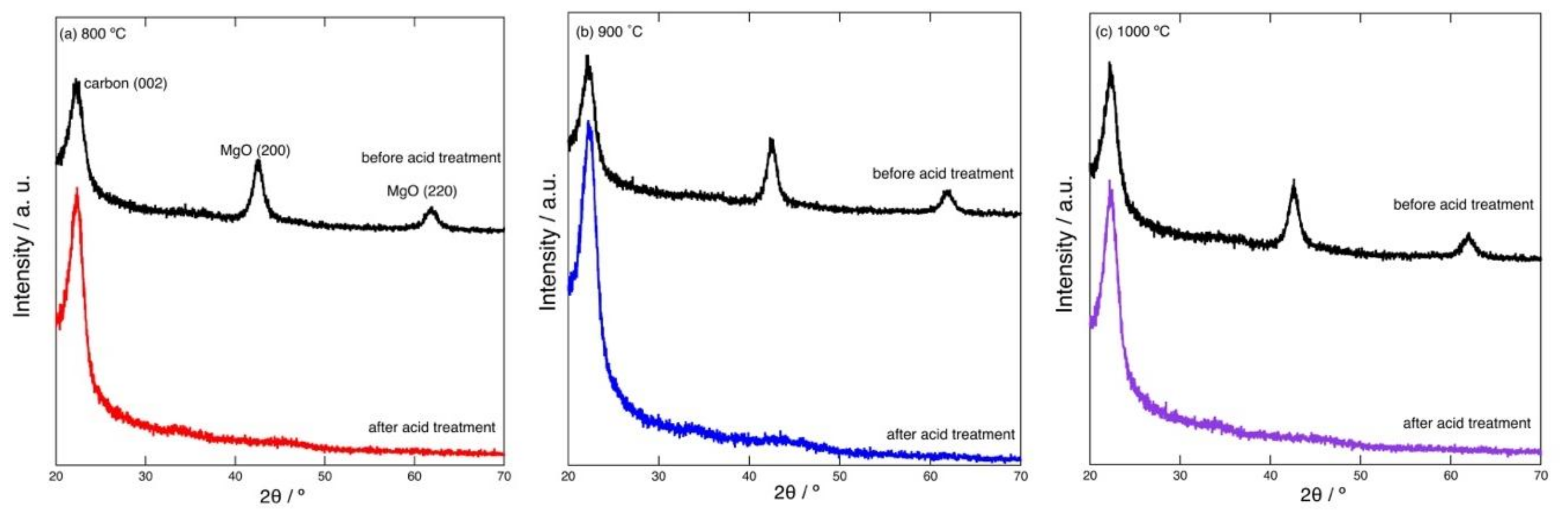
The powder mixture was white before heating, while its color changed to black after heating. Carbonization of the mixture was thus visually confirmed. Figure 1 shows example XRD patterns of the carbonized products prepared by heating at 800–1000 °C. The pattern of the product before acid treatment indicates that the product consists of turbostratic graphite-like carbon and MgO. The characteristic peaks arising from the (002) plane of graphite and the (200) and (220) planes of MgO are seen in the pattern. Other peaks of graphite are quite broad and hard to distinguish, indicating that the resultant carbon has a highly turbostratic structure. After the acid treatment, the peaks of MgO disappeared; the acid treatment removed MgO and resulted in the formation of porous carbon. The crystallite sizes of the resultant MgO generated at 800–1000 °C were roughly estimated using Scherrer’s Equation (1).
where D is the crystallite size (in nm), K is a constant (0.9 used herein), λ is the wavelength of CuKα radiation (0.15482 nm), β is the half-width of the XRD peak used for the calculation (in rad), and cosθ is the cosine of the Bragg angle. Here, the half-width observed for the MgO (220) peak was used to calculate D. Although it was quite difficult to accurately calculate the value of D based on the currently available XRD results, D was estimated to be 5–6 nm. As described below, this size is comparable to the peak mesopore size determined via gas adsorption/desorption isotherms.
D = Kλ/(βcosθ)
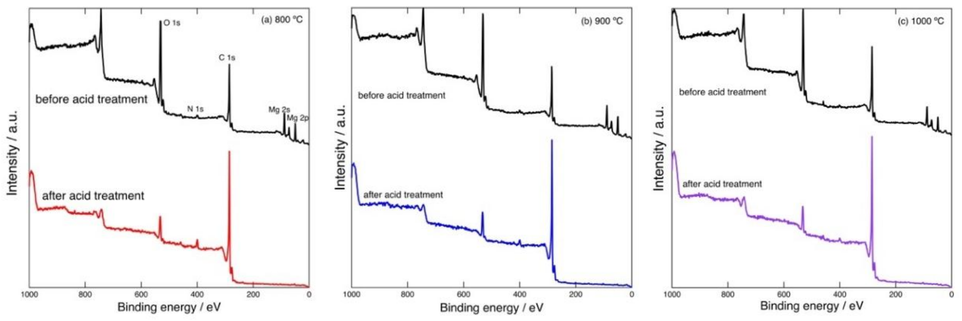
Figure 2 shows example XPS spectra of the carbonized products prepared by heating at 800–1000 °C. In the spectrum of the product before acid treatment, C 1s, O 1s, N 1s, Mg 2s, and Mg 2p signals can be observed. After the acid treatment, the Mg 2s and 2p peaks disappear. This indicates the removal of MgO.
The elemental contents (in mol%) of the products before and after the acid treatment are listed in Table 1. These values were calculated based on areas of the narrow scan XPS spectra. Although it has been pointed out that quantitative analysis of porous materials based on XPS data is not reliable due to the surface roughness [5], distinct changes in the elemental contents before and after the acid treatment is expected to be revealed even by means of XPS. The Mg content was significantly decreased by the acid treatment for all the samples. The amount of O also decreased after acid treatment, while some residual O remained; although O in the form of MgO was removed by the acid, O contained in surface functional groups formed by oxidation (caused by residual gaseous oxygen) and/or originally contained in PVP would be left in the samples.
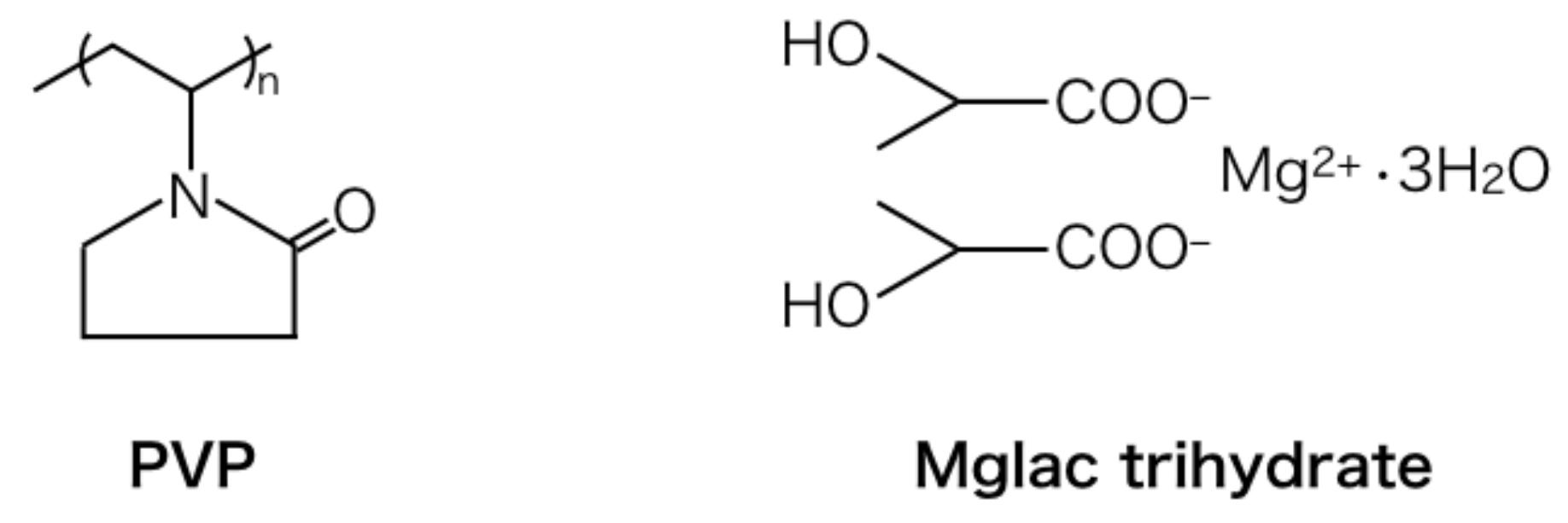
Figure 3 shows the structures of PVP and Mglac trihydrate. The molar concentrations of C, N, O, and Mg in the starting materials can be estimated on the basis of these chemical structures. The contents for the PVP/Mglac trihydrate (10 g + 10 g) mixture are estimated as follows: 58 mol% C, 7 mol% N, 33 mol% O, and 3 mol% Mg (the sum of these contents is 101% because the values are rounded to integers). Here, the amount of hydrogen is omitted from this estimation.
Comparing these values with the contents shown in Table 1, it is found that C, N, and O were markedly eliminated by heating and hence, the Mg content relatively increased. During the heating process, considerable amounts of C, N, and O were converted into gaseous compounds; the final weight of the resultant products (N-doped carbon/MgO) after the heating was about 1/10 of the weight of the starting materials. In contrast, Mg was not removed in the form of volatile products and therefore, the resulting content of Mg was relatively high. Following the acid treatment, in which the Mg and O contained in MgO were removed, the relative contents of C and N increased; N-doped carbon was thus formed. About 60% of the N contained in the original PVP remained in the product after heating at 800 °C, but the N content decreased as the heating temperature was increased. This trend is quite common among various nitrogen-containing carbons, such as carbonaceous products derived from polyacrylonitrile. In the case of N-doped carbon derived from PVP/magnesium acetate, a similar change in the N content has been observed [5]. It was found that the MgO precursor does not significantly affect the N content. For the N-doped carbons derived from PVP/magnesium acetate, the N content was reported to be approximately 2–7 wt% (2–6 mol%) depending on the heating temperature. These values are comparable to the N contents observed in previous studies, indicating that the N content is not dependent on the MgO precursor.
3.2. Effect of Heating Temperature on Pore Size Distribution
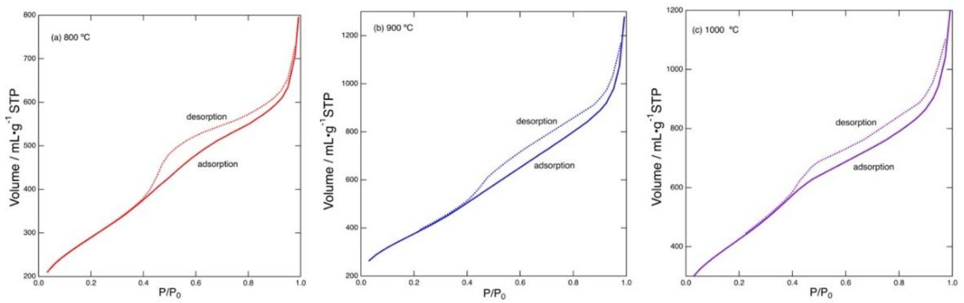
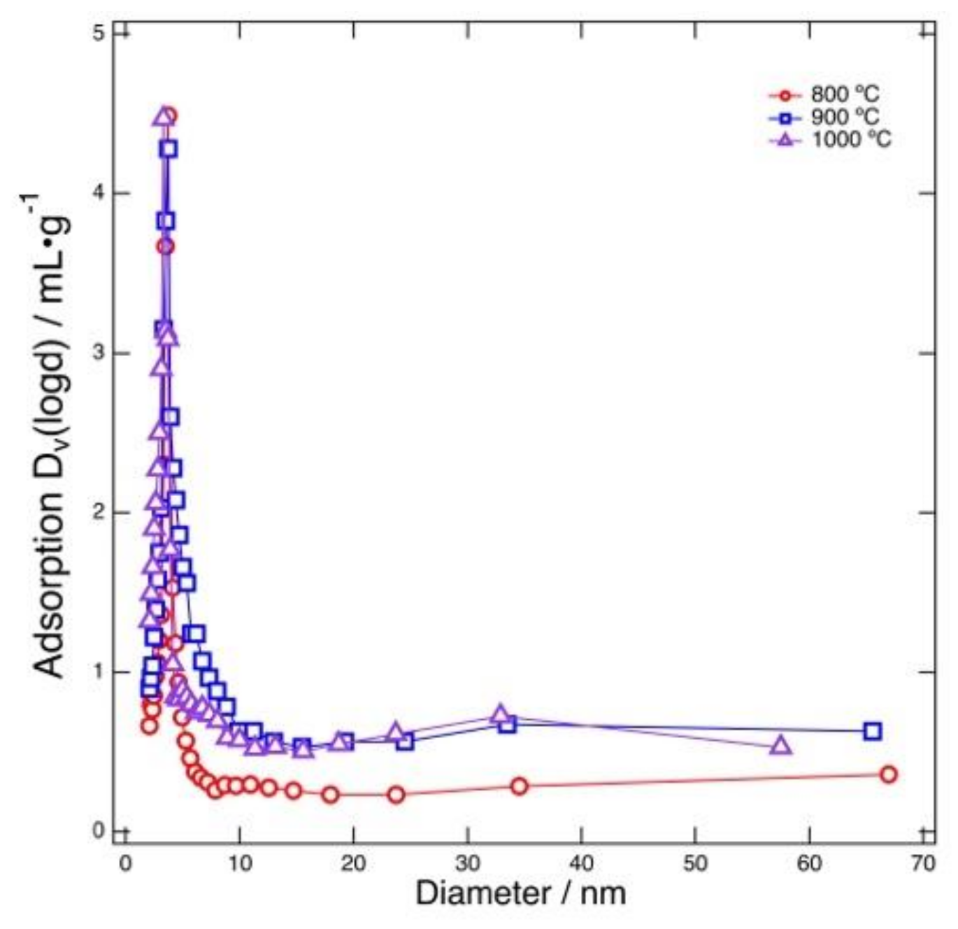
Figure 4 shows nitrogen gas adsorption/desorption isotherms recorded for the carbonized products prepared by heating at 800–1000 °C. These isotherms show a common feature typical for porous materials possessing mesopores (pore width: 2–50 nm); the isotherms show hysteresis related to condensation of gas occurring in the mesopores (IUPAC classification: Type IV) [31]. All the samples showed isotherms with this type of hysteresis. The number of micropores (pore width: less than 2 nm) was found to be minor. The pore size distribution can be analyzed on the basis of the isotherm data. Figure 5 shows the results of BJH pore size distribution analysis performed for the products obtained by heating at 800–1000 °C followed by acid treatment. For all the samples, the major pore size was about 4 nm. Mesopores possessing this size were generated with the MgO template. As previously described, the crystallite size of the MgO precursor was 5–6 nm, as determined from the XRD results. Although this value is slightly larger than the size of the observed peak pore size (4 nm), considering the accuracy of the estimated crystallite size, the crystallite size was comparable to the typical mesopore size calculated using the BJH method. This indicates that the MgO template was trapped in the carbonized products in the form of nano-sized single crystals. In addition, the BJH mesopore size was comparable to that of previously reported MgO-templated carbons, indicating that the BJH mesopore size corresponds to the size of the MgO template. However, this size was different from the value reported for MgO-templated carbons derived from PVP/magnesium acetate, for which the reported pore size was smaller than 6 nm without any peaks [5]. Moreover, different peak pore sizes have been reported for PVA/magnesium citrate (5 nm), PVA/magnesium acetate (13 nm), and PVA/magnesium gluconate (2 nm) [27]. This result shows that the pore size can also be controlled by choosing the MgO source in the case of N-doped carbon derived from PVP.
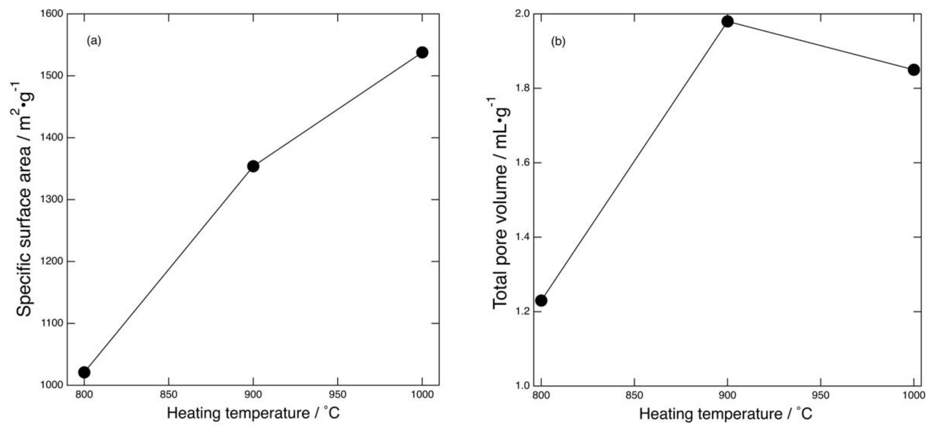
As can be seen in Figure 5, the peak mesopore size (4 nm) and total pore volume of mesopores around the peak size do not strongly depend on the heating temperature. On the other hand, the number of mesopores with larger size was found to increase when the heating temperature was increased. From these results, it was found that the mesopores around 4 nm in width were formed from the MgO template, while the larger mesopores were generated without MgO. The peak mesopore size reflects the crystalline size of MgO formed from Mglac and it remains constant regardless of the heating temperature; if the crystalline size of MgO depends on heating temperature, the peak size should be determined by a temperature-dependent crystal growth rate. The temperature-independent MgO template size is supported by the crystallite size estimation based on the XRD results described above. These results indicate that the crystal growth process was almost the same over the range of temperatures examined in this work. The larger mesopores were consequently generated without the MgO template and contributed to producing a large specific surface area. Figure 6 shows the specific surface area and total pore volume of the mesoporous carbons as a function of heating temperature. It can be seen that the specific surface area increased as the heating temperature was increased. The area of the product heated at 1000 °C was as large as 1540 m2·g−1. As described above, the total volume of mesopores around the peak size was nearly equal for all the products, and hence there was little difference in the specific surface area provided by these mesopores. In contrast, the larger mesopores played a major role in determining the overall specific surface area and total pore volume. The total pore volume increased with the increase in heating temperature, but the volume of the sample prepared at 1000 °C was slightly smaller than that of the sample prepared at 900 °C. The underlying mechanism of the lower pore volume remains ambiguous and will be the subject of future study. The difference in the specific surface area of the mesoporous carbons (1000–1540 m2·g−1) was mainly caused by the generation of these larger mesopores. Similarly, the total pore volume differed by larger mesopore formation. The larger mesopores were likely generated by thermal decomposition of PVP. Although the surface areas provided by mesopores generated with and without MgO template were not separately determined in this work, considering the temperature-independent peak mesopore size and volume, the larger mesopore was formed through a process other than MgO templating. The mechanism that yielded the larger mesopore will be elucidated in a future study. Therefore, to develop mesoporous carbon with a controlled pore size distribution by a MgO-template technique, we should take the pore sizes determined both with and without taking MgO into account.
4. Concluding Remarks
In this study, N-doped mesoporous carbons were derived from PVP/Mglac mixtures. N-doped carbon possessing a unique peak pore width (4 nm) was prepared by using Mglac, indicating that the pore size distribution can also be controlled by choosing the MgO source in the case of N-doped mesoporous carbon. This peak mesopore size did not depend on the heating temperature and was comparable to the MgO crystallite size for all samples prepared at 800–1000 °C. The MgO template was generated in the form of nano-sized single crystals. The volume of larger mesopores generated without the MgO template increased with increasing heating temperature and the specific surface area consequently increased. The larger mesopores were likely generated through thermal decomposition of PVP. The N content in the products decreased with increasing heating temperature. However, comparing the results of this study with those of literature reports using magnesium acetate as the MgO precursor, the N content was found to be irrelevant to the MgO precursor used.
The remaining problems are listed below and will be elucidated in future studies.
- Elucidation of the mechanism of the larger pore formation: The process of MgO-templated mesopore formation can be simply explained, but that of the larger mesopores has not been sufficiently elucidated in terms of PVP decomposition. The generation of larger mesopores may be related to the elimination of nitrogen as gaseous products at high temperature.
- Microscopic observation of pore structure: While the pore size distribution was determined using gas adsorption/desorption isotherms herein, transmission electron microscopy (TEM) will be useful to reveal the spatial arrangement of the mesopores.
- Use of metal oxides other than MgO: Although in this study we used MgO as a template, similar procedures are possible if a water-soluble template precursor is used.
- The effect of temperature ramp rate on pore structure: The temperature ramp rate dependence of the mesopore size was not determined herein. However, it has been reported that higher ramp rates result in micropore formation for the MgO/polyvinyl alcohol system [23]. This phenomenon may also be observed for the MgO/PVP system.
Evaluation of the products as materials for practical use is important. For example, N-doped mesoporous carbons have been studied mainly as electrode materials for electric double layer capacitors, lithium-ion capacitors, fuel cells, and so on. Until now, we have focused our interest mainly on the pore size distribution of MgO-templated N-doped carbon, while the characterization of the prepared products as electrode materials has been omitted. To evaluate the electrode characteristics of the products, electrostatic capacities such as double layer capacitance and pseudocapacitance should be measured by means of electrochemical techniques. Additionally, surface functional groups containing heteroatoms (N, O, etc.) should be identified. These characterization experiments will be subjects for future study.
Author Contributions
Conceptualization, T.T.; methodology, T.T. and M.K.; validation, T.T. and M.K.; investigation, M.K.; data curation, T.T. and M.K.; writing, T.T.; visualization, T.T.; supervision, T.T.
Funding
This research received no external funding.
Acknowledgments
The XPS experiments were carried out using an X-ray photoelectron spectrometer (JEOL JPS-9200) installed at the Laboratory of XPS analysis, Hokkaido University (Technician: Keita Suzuki), supported by the Nanotechnology Platform Program of the Ministry of Education, Culture, Sports, Science and Technology (MEXT), Japan. The nitrogen gas adsorption/desorption isotherms were recorded using a gas sorption analyzer (Quantachrome Autosorb) installed at the Institute of Catalysis, Hokkaido University (Technician: Shuhei Shimoda); the analyzer is registered in the Open Facility system managed by the Global Facility Center, Creative Research Institution, Hokkaido University. We would like to thank Editage (www.editage.jp) for English language editing.
Conflicts of Interest
The authors declare no conflict of interest.
References
- Puziy, A.M.; Poddubnaya, O.I. The properties of synthetic carbon derived from nitrogen- and phosphorus-containing polymer. Carbon 1998, 36, 45–50. [Google Scholar] [CrossRef]
- Lahaye, L.; Nansé, G.; Bageev, A.; Strelko, V. Porous structure and surface chemistry of nitrogen containing carbons from polymers. Carbon 1999, 37, 585–590. [Google Scholar] [CrossRef]
- Lota, G.; Grzyb, B.; Machnikowska, H.; Machnikowski, J.; Frackowiak, E. Effect of nitrogen in carbon electrode on the supercapacitor performance. Chem. Phys. Lett. 2005, 404, 53–58. [Google Scholar] [CrossRef]
- Maldonado, S.; Stevenson, K.J. Influence of Nitrogen Doping on Oxygen Reduction Electrocatalysis at Carbon Nanofiber Electrodes. J. Phys. Chem. B 2005, 109, 4707–4716. [Google Scholar] [CrossRef]
- Konno, H.; Onishi, H.; Yoshizawa, N.; Azumi, K. MgO-templated nitrogen-containing carbons derived from different organic compounds for capacitor electrodes. J. Power Source 2010, 195, 667–673. [Google Scholar] [CrossRef]
- Zhang, L.; Xia, Z. Mechanisms of Oxygen Reduction on Nitrogen-Doped Graphene for Fuel Cells. J. Phys. Chem. C 2011, 115, 11170–11176. [Google Scholar] [CrossRef]
- Garcia, B.B.; Candelaria, S.L.; Cao, G. Nitrogenated porous carbon electrodes for supercapacitor. J. Mater. Sci. 2012, 47, 5996–6004. [Google Scholar] [CrossRef]
- Zhang, L.L.; Zhao, X.; Ji, H.; Stoller, M.D.; Lai, L.; Murali, S.; Mcdonnell, S.; Cleveger, B.; Wallace, R.M.; Ruoff, R.S. Nitrogen doping of graphene and its effect on quantum capacitance, and a new insight on the enhanced capacitance on N-doped carbon. Energy Environ. Sci. 2012, 5, 9618–9625. [Google Scholar] [CrossRef]
- Hu, Y.; Liu, H.; Ke, Q.; Wang, J. Effects of nitrogen doping on supercapacitor performance of a mesoporous carbon electrode produced by a hydrothermal soft-templating process. J. Mater. Chem. A 2014, 2, 11753–11758. [Google Scholar] [CrossRef]
- Soares, O.S.G.P.; Rocha, R.P.; Gonçalves, A.G.; Figueiredo, J.L.; Órfão, J.J.M.; Pereira, M.F.R. Easy method to prepare N-doped carbon nanotubes by ball milling. Carbon 2015, 91, 114–121. [Google Scholar] [CrossRef]
- Rocha, I.M.; Soares, O.S.G.P.; Fernandes, D.M.; Freire, C.; Figueiredo, J.L.; Pereira, M.F.R. N-doped Carbon Nanotubes for the Oxygen Reduction Reaction in Alkaline Medium: Synergistic Relationship between Pyridinic and Quartary Nitrogen. ChemistrySelect 2016, 1, 2522–2530. [Google Scholar] [CrossRef]
- Soares, O.S.G.P.; Rocha, R.P.; Gonçalves, A.G.; Figueiredo, J.L.; Órfão, J.J.M.; Pereira, M.F.R. Highly active N-doped carbon nanotubes prepared by an easy ball milling method for advanced oxidation processes. Appl. Catal. B Environ. 2016, 192, 296–303. [Google Scholar] [CrossRef]
- Itoi, H.; Nishihara, H.; Kyotani, T. Effect of Heteroatoms in Ordered Microporous Carbons on Their Electrochemical Capacitance. Langmuir 2016, 32, 11997–12004. [Google Scholar] [CrossRef] [PubMed]
- Huang, J.; Han, J.; Gao, T.; Zhang, X.; Li, J.; Li, Z.; Xu, P.; Song, B. Metal-free nitrogen-doped carbon nanoribbons as highly efficient electrocatalysts for oxygen reduction reaction. Carbon 2017, 124, 34–41. [Google Scholar] [CrossRef]
- Chen, M.; Xuan, H.; Zheng, X.; Liu, J.; Dong, X.; Xi, F. N-doped mesoporous by a hard-template strategy associated with chemical activation and its enhanced supercapacitor performance. Electrochim. Acta 2017, 238, 269–277. [Google Scholar] [CrossRef]
- Huang, X.; Yin, X.; Yu, X.; Tian, J.; Wu, W. Preparation of nitrogen-doped carbon materials based on polyaniline fiber and their oxygen reduction properties. Coll. Surf. A Physicochem. Eng. Aspects 2018, 539, 163–170. [Google Scholar] [CrossRef]
- Inagaki, M.; Toyoda, M.; Soneda, Y.; Morishita, T. Nitrogen-doped carbon materials. Carbon 2018, 132, 104–140. [Google Scholar] [CrossRef]
- Sun, Y.-N.; Sui, Z.-Y.; Li, X.; Xiao, P.-W.; Wei, Z.-X.; Han, B.-H. Nitrogen-Doped Porous Carbons Derived from Polypyrrole-Based Aerogels for Gas Uptake and Supercapacitors. ACS Appl. Nano Mater. 2018, 1, 609–616. [Google Scholar] [CrossRef]
- Lv, Q.; Si, W.; He, J.; Sun, L.; Zhang, C.; Wang, N.; Yang, Z.; Li, X.; Wang, X.; Deng, W.; et al. Selectively nitrogen-doped carbon materials as superior metal-free catalysts for oxygen reduction. Nat. Commun. 2018, 9, 3376. [Google Scholar] [CrossRef] [PubMed]
- Ning, X.; Li, Y.; Ming, J.; Wang, Q.; Wang, H.; Cao, Y.; Peng, F.; Yang, Y.; Yu, H. Electronic synergism of pyridinic- and graphitic-nitrogen on N-doped carbons for the oxygen reduction reaction. Chem. Sci. 2019, 10, 1589–1596. [Google Scholar] [CrossRef]
- Morishita, T.; Soneda, Y.; Tsumura, T.; Inagaki, M. Preparation of porous carbons from thermoplastic precursors and their performance for electric double layer capacitors. Carbon 2006, 44, 2360–2367. [Google Scholar] [CrossRef]
- Morishita, T.; Ishihara, K.; Kato, M.; Inagaki, M. Preparation of a carbon with a 2 nm pore size and of a carbon with bi-modal pore size distribution. Carbon 2007, 45, 209–211. [Google Scholar] [CrossRef]
- Inagaki, M.; Kobayashi, S.; Kojin, N.; Tanaka, N.; Morishita, T.; Tryba, B. Pore structure of carbons coated on ceramic particles. Carbon 2004, 42, 3153–3158. [Google Scholar] [CrossRef]
- Morishita, T.; Suzuki, T.; Nishikawa, T.; Tsumura, T.; Inagaki, M. Preparation of porous carbons by carbonization of the mixtures of thermoplastic precursors with MgO. TANSO 2005, 2005, 226–231. [Google Scholar] [CrossRef]
- Morishita, T.; Suzuki, R.; Tsumura, T.; Habazaki, H.; Inagaki, M. Preparation of mesoporous carbons by carbonization of the mixtures of poly(vinyl alcohol) with magnesium salts. TANSO 2006, 2006, 220–226. [Google Scholar] [CrossRef]
- Morishita, T.; Ishihara, K.; Kato, M.; Tsumura, T.; Inagaki, M. Mesoporous carbons prepared from mixtures of magnesium citrate with poly(vinyl alcohol). TANSO 2007, 2007, 19–24. [Google Scholar] [CrossRef]
- Morishita, T.; Wang, L.; Tsumura, T.; Toyoda, M.; Konno, H.; Inagaki, M. Pore structure and application of MgO-templated carbons. TANSO 2010, 2010, 60–68. [Google Scholar] [CrossRef]
- Soneda, Y.; Yamaguchi, T.; Imoto, K.; Kodama, M.; Morishita, T.; Orikasa, H. Performance of MgO-templated mesoporous carbons as electrode materials in lithium-ion capacitor. TANSO 2013, 2013, 57–59. [Google Scholar] [CrossRef]
- Brunauer, S.; Emmett, P.H.; Teller, E. Adsorption of Gases in Multimolecular Layers. J. Am. Chem. Soc. 1938, 60, 309–319. [Google Scholar] [CrossRef]
- Barrett, E.P.; Joyner, L.G.; Halenda, P.P. The Determination of Pore Volume and Area Distributions in Porous Substances. I. Computations from Nitrogen Isotherms. J. Am. Chem. Soc. 1951, 73, 373–380. [Google Scholar] [CrossRef]
- Sing, K.S.W.; Everett, D.H.; Haul, R.A.W.; Moscou, L.; Pierotti, R.A.; Rouquérol, J.; Siemieniewska, T. Reporting Physisorption Data for Gas/Solid Systems with Special Reference to the Determination of Surface Area and Porosity. Pure Appl. Chem. 1985, 57, 603–619. [Google Scholar] [CrossRef]
Figure 1.
XRD patterns of the carbonized products prepared by heating at (a) 800 °C, (b) 900 °C, and (c) 1000 °C: Before sulfuric acid treatment (black) and after sulfuric acid treatment (red, blue, and purple).
Figure 1.
XRD patterns of the carbonized products prepared by heating at (a) 800 °C, (b) 900 °C, and (c) 1000 °C: Before sulfuric acid treatment (black) and after sulfuric acid treatment (red, blue, and purple).

Figure 2.
XPS spectra of the carbonized products prepared by heating at (a) 800 °C, (b) 900 °C, and (c) 1000 °C: Before sulfuric acid treatment (black) and after sulfuric acid treatment (red, blue, and purple).
Figure 2.
XPS spectra of the carbonized products prepared by heating at (a) 800 °C, (b) 900 °C, and (c) 1000 °C: Before sulfuric acid treatment (black) and after sulfuric acid treatment (red, blue, and purple).

Figure 3.
Structures of polyvinylpyrrolidone (PVP) and magnesium lactate (Mglac) trihydrate.

Figure 4.
Adsorption and desorption isotherms of the carbonized products prepared by heating at (a) 800 °C, (b) 900 °C, and (c) 1000 °C.
Figure 4.
Adsorption and desorption isotherms of the carbonized products prepared by heating at (a) 800 °C, (b) 900 °C, and (c) 1000 °C.

Figure 5.
Pore size distributions of carbonized products.

Figure 6.
Specific surface area (a) and total pore volume (b) as a function of heating temperature.


Table 1.
Amounts of C, N, O, and Mg in the carbonized products (in mol%).
| Heating Temperature | Acid Treatment | C | N | O | Mg |
|---|---|---|---|---|---|
| 800 °C | Before | 36 | 2 | 29 | 33 |
| After | 85 | 5 | 9 | 1 | |
| 900 °C | Before | 34 | 2 | 29 | 36 |
| After | 87 | 3 | 9 | 1 | |
| 1000 °C | Before | 48 | 2 | 28 | 22 |
| After | 87 | 2 | 10 | 1 |
© 2019 by the authors. Licensee MDPI, Basel, Switzerland. This article is an open access article distributed under the terms and conditions of the Creative Commons Attribution (CC BY) license (http://creativecommons.org/licenses/by/4.0/).
Share and Cite
MDPI and ACS Style
Takada, T.; Kurihara, M. Preparation of MgO-Templated N-Doped Mesoporous Carbons from Polyvinylpyrrolidone: Effect of Heating Temperature on Pore Size Distribution. C 2019, 5, 15. https://doi.org/10.3390/c5020015
AMA Style
Takada T, Kurihara M. Preparation of MgO-Templated N-Doped Mesoporous Carbons from Polyvinylpyrrolidone: Effect of Heating Temperature on Pore Size Distribution. C. 2019; 5(2):15. https://doi.org/10.3390/c5020015
Chicago/Turabian StyleTakada, Tomoya, and Mayu Kurihara. 2019. "Preparation of MgO-Templated N-Doped Mesoporous Carbons from Polyvinylpyrrolidone: Effect of Heating Temperature on Pore Size Distribution" C 5, no. 2: 15. https://doi.org/10.3390/c5020015
Note that from the first issue of 2016, this journal uses article numbers instead of page numbers. See further details here.