1. Introduction
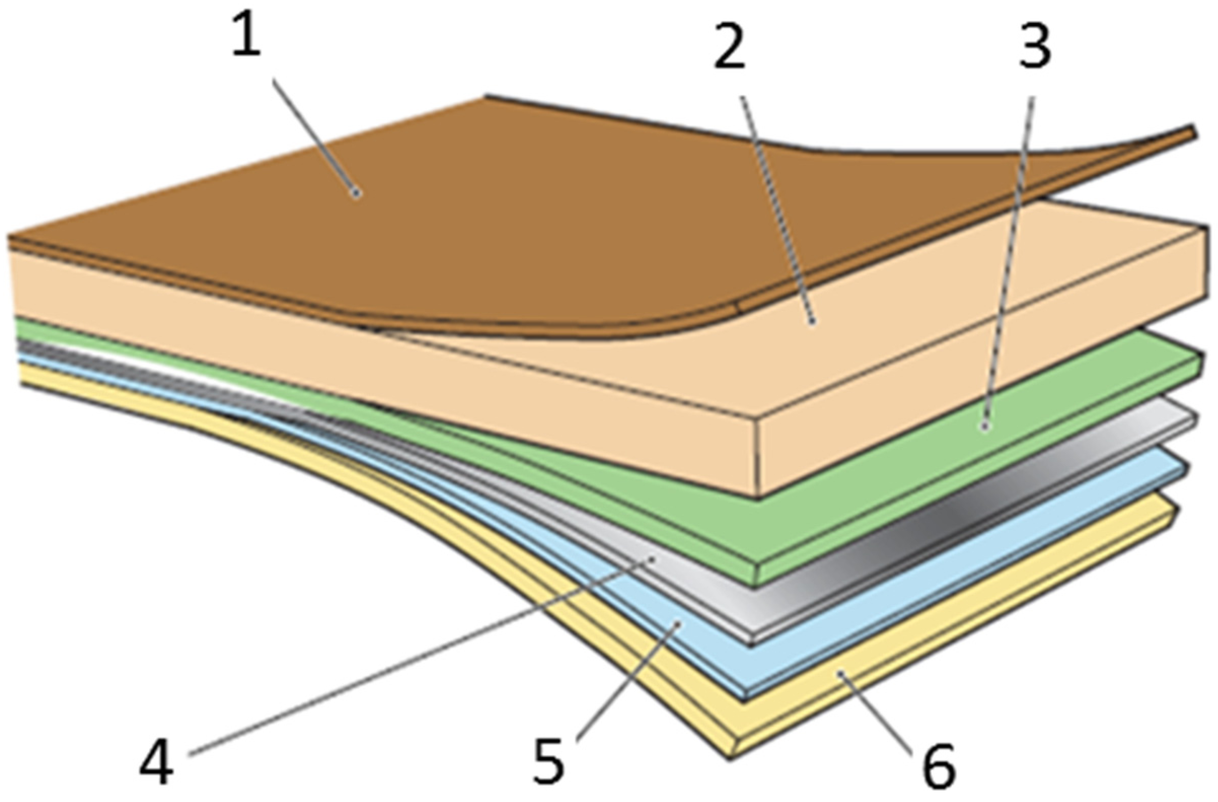
Beverage packaging is commonly made of the functionally layered composite sketched in
Figure 1. A paperboard ply (2 in the sketch) confers the main stiffness and strength to this material system, while a thin aluminum foil (4) prevents light and oxygen penetration and natural or artificial polymer layers (1, 3, 5, 6) act as a barrier toward moisture and work as adhesives [
1].
Figure 1.
Typical composition and functionality of beverage packaging material: (1) external plastic layer, protects against outside moisture and enables sealing; (2) paperboard, gives stability and strength and enables printing; (3) lamination layer, enables adhesion between aluminum foil and paperboard; (4) aluminum foil, acts as oxygen, flavor and light barrier; (5) adhesion layer between the aluminum foil and the internal plastic layer; (6) internal plastic layer, seals in the liquid product and enables hermetical closure.
The packaging components are assembled together by thermo-mechanical action and some of the polymers are melted during manufacturing. Thus, the production process involves several steps at different temperature and pressure values that can influence the characteristics of this material system.
The cap opening area usually consists of aluminum and polymer layers only. The mechanical properties of this laminate are of particular interest due to its peculiar twofold role: on one hand, it should resist the external actions and preserve the packaging content; on the other, it should be easily cut by a package opening device operated by the human force.
The response of the aluminum-polymer laminate to different loading conditions and its interaction with the surrounding composite can be reproduced by uniaxial tensile tests [
2] or inflation tests [
3] carried out on heterogeneous material samples, shown for instance in
Figure 2 and
Figure 3. The relationship between the applied force (or pressure) and the induced deformation can be complemented by local measurements based on full-field techniques like digital image correlation or laser profilometry. Qualitative and quantitative information about the overall and local mechanical characteristics can be identified, then, with the aid of simulation models of the experiments.
The investigations documented in [
2,
3] show that the material failure is usually initiated by the separation of the aluminum layer from the paperboard composite at the boundary between these dissimilar media. This phenomenon has been interpreted at the light of brittle or quasi-brittle fracture models in [
2,
3,
4,
5], consistently with the smaller rupture strain and meaningful reduction of toughness exhibited by free-standing thin metal foils compared to the corresponding bulk materials [
6,
7].
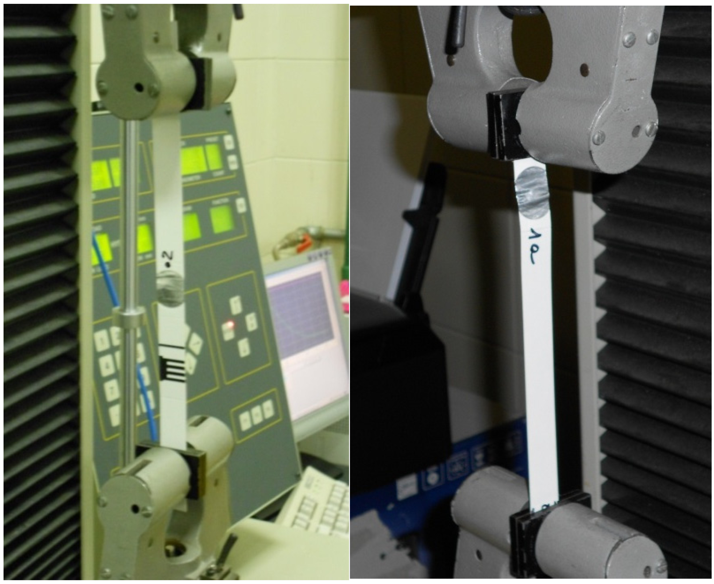
Figure 2.
Heterogeneous material samples subjected to tensile test.
Figure 2.
Heterogeneous material samples subjected to tensile test.
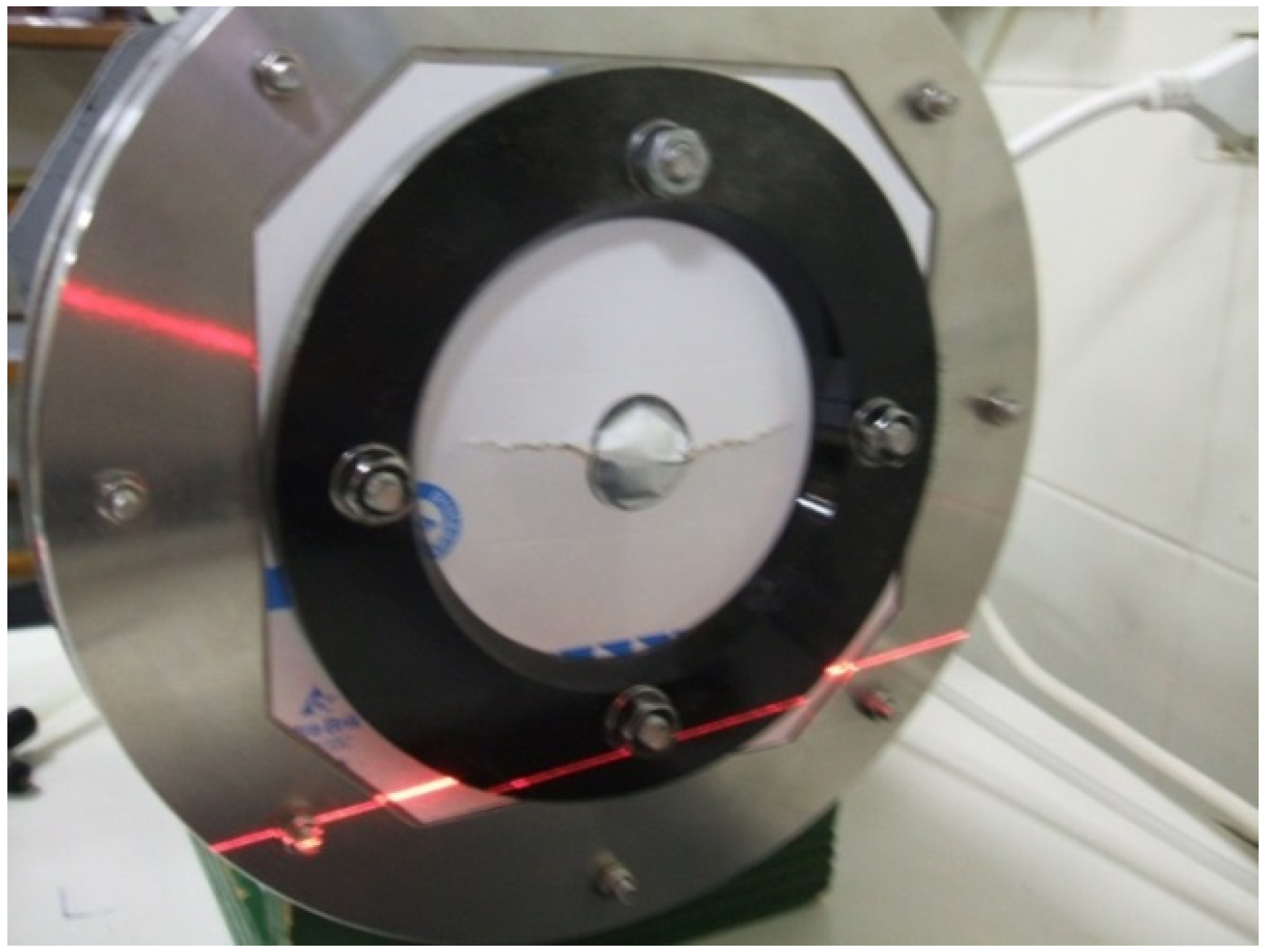
Figure 3.
Failure mode of a heterogeneous material sample subjected to inflation test.
Figure 3.
Failure mode of a heterogeneous material sample subjected to inflation test.
However, fractographical examinations reported in [
8] suggest that the material separation may be rather produced by necking, in other words, by a typical elastic-plastic phenomenon. Thus, the decay of the nominal material properties may be attributed to the localization of plastic deformation in narrow bands, induced by stress concentration in correspondence of some imperfection, rather than to the constitutive softening usually associated to grain boundary cracking or cleavage. On the other hand, these alternative or competing failure mechanisms may be enhanced or controlled by the coupling of the aluminum foil with the polymeric layers [
9,
10,
11,
12,
13].
These issues are discussed in this contribution with the aid of simulation models of some experimental test.
2. Experimental Results
Figure 2 shows heterogeneous specimens consisting of material strips (15 mm wide) cut from reel and from packages in correspondence of the circular cap opening area (of about 24 mm diameter). The samples are subjected to uniaxial tensile tests conforming to standards [
14]. Typical results obtained under displacement control are reported in
Figure 4.
Figure 4.
(a,b) Overall load-displacement curves concerning specimens cut from different material batches and subjected to uniaxial tension test; (c) final configuration of specimens after their removal from the testing apparatus.
Figure 4.
(a,b) Overall load-displacement curves concerning specimens cut from different material batches and subjected to uniaxial tension test; (c) final configuration of specimens after their removal from the testing apparatus.
The experiment can be monitored by a digital camera, acquiring a sequence of snapshots at different load levels. The correlation among these images shows that the strain concentrates mostly on the aluminum laminate inclusion. The stiffer paperboard composite undergoes an almost rigid body motion and can be thus considered as an extension of the gripping apparatus [
2]. Therefore, the typical load displacement curves drawn in
Figure 4 essentially reflect the mechanical response of the cap opening area.
The graphs in
Figure 4a,b concern tests leading to the ultimate deformation modes visualized in
Figure 4c. The horizontal plateau in the graphs of
Figure 4a corresponds to the large irreversible extension experienced by the polymeric film after separation from the aluminum foil; this failure pattern is exhibited by the sample marked 3a in
Figure 4c (left picture). The progressive decay of the overall material strength represented in
Figure 4b is rather obtained when aluminum peeling is prevented by the adhesion among the layers, leading to the final configuration of the sample marked 2a in
Figure 4c (on the right).
The alternative responses shown by
Figure 4 can be related to the different interaction between the aluminum and the polymer layers, depending on the relevant interface characteristics. The underlying mechanical phenomena have been explored by means of some simulation models of the experiments, based on available information concerning the single components.
The graph drawn by a continuous line in
Figure 5a schematizes the typical response to uniaxial tensile test of homogeneous samples obtained from the thin aluminum foils employed in beverage packaging. The cut surfaces are usually carefully inspected at the microscope and the specimens embedding significant imperfections are discarded. Thus, the stress-strain curves concerning nominally identical samples are usually rather repetitive. Still, the failure strain remains rather scattered.
Figure 5.
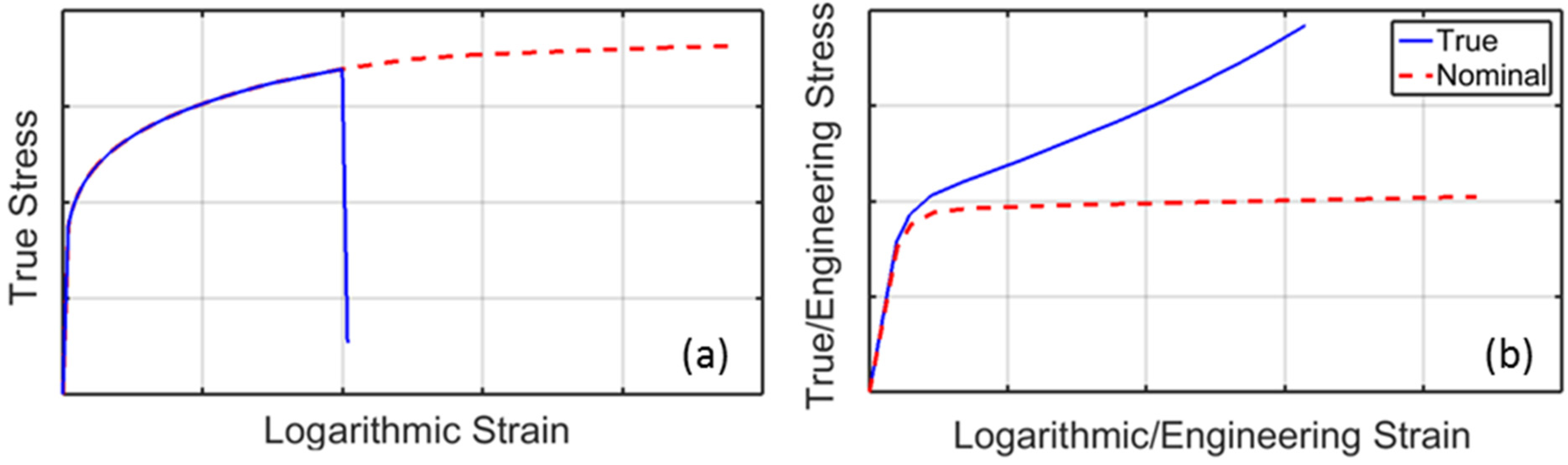
(a) Typical stress-strain response of free-standing aluminum foils (continuous line) and idealized constitutive law (dashed); (b) true stress-strain curve of the polyethylene layers (continuous line) and the resulting nominal response (dashed).
Figure 5.
(a) Typical stress-strain response of free-standing aluminum foils (continuous line) and idealized constitutive law (dashed); (b) true stress-strain curve of the polyethylene layers (continuous line) and the resulting nominal response (dashed).
The polyethylene response is visualized in
Figure 5b in terms of both nominal and true stress and strain measures. The large deformation potentially undergone by this material makes the difference rather significant. In particular, it can be noticed that the horizontal plateau already evidenced in
Figure 4a is caused by the meaningful contraction of the loaded material section for large longitudinal strains.
Typical values of the constitutive parameters are reported in
Table 1.
Table 1.
Characteristic parameters of aluminum laminates in beverage packaging.
Table 1.
Characteristic parameters of aluminum laminates in beverage packaging.
| Component | Thickness (μm) | Young’s Modulus (MPa) | Yield Limit * (MPa) | Failure/Plateau Stress (MPa) | Failure Strain (-) |
|---|
| Aluminum foil | 6–9 | 30,000–45,000 | 30–35 | 50–70 (F) | 0.02–0.04 |
| Polyethylene films | 80–110 † | 120–200 | 4–6 | 8–12 (P) | - |
3. Modeling Issues
The experimental results reported in [
2,
3], recovered from uniaxial and inflation tests performed with the equipment visualized in
Figure 2 and
Figure 3, show that the failure of the laminate inclusion forming the cap opening area of beverage packaging is usually initiated by the separation of the aluminum foil from the surrounding material. In tensile tests, this event is often singled out by a sudden drop of the overall force at almost constant elongation, which is visible in the graphs reported in
Figure 4 just beyond the peak load.
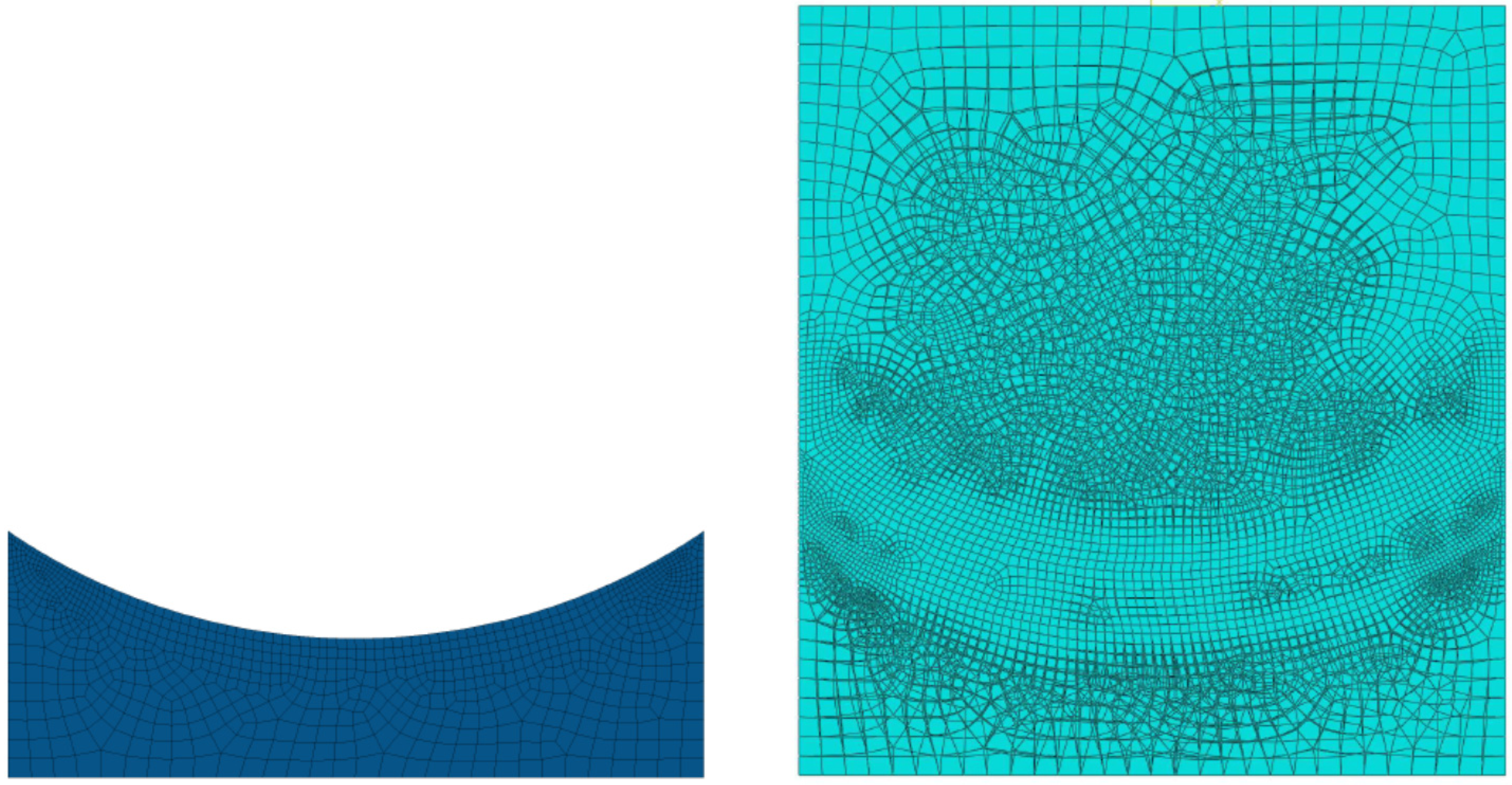
Aluminum starts detaching from the positions where finite element (FE) analyses evidence stress concentration; see e.g.,
Figure 6 and
Figure 7. The simulation model of the tensile test visualized in
Figure 6 is based on the independent discretization of each material layer by four-node plane stress elements. The results shown in
Figure 7 are obtained in the hypothesis of perfect adhesion among the plies, enforced by assuming that the nodal displacements of each discretization layer are interpolation of the nearest ones on adjacent layers, account taken of the connection details visualized by micrographs of the laminate cross section.
Figure 6.
FE model of the paperboard portion (left) and overall assembly (right).
Figure 6.
FE model of the paperboard portion (left) and overall assembly (right).
Figure 7.
Magnitude distribution of the stress components in the aluminum layer; from the left: stress parallel and orthogonal to the loading direction and in-plane shear.
Figure 7.
Magnitude distribution of the stress components in the aluminum layer; from the left: stress parallel and orthogonal to the loading direction and in-plane shear.
Aluminum and polyethylene are characterized by an elastic-plastic constitutive law based on the classical Hencky-Huber-von Mises criterion with hardening/softening rules reproducing the true uniaxial stress-strain responses schematized in
Figure 5. Due to the high stiffness resulting from its dominant thickness (400 μm) and to its marginal role in the phenomena to be reproduced, paperboard is assumed isotropic linear elastic. The numerical analyses are performed by a widely used commercial code [
15] including the large displacement and large plastic strain option.
The experimental results concerning tensile tests summarized in
Figure 4 indicate that the maximum force is attained at about 2 mm elongation, which corresponds to about 8% nominal strain in the laminate inclusion. These values are much larger than the typical failure level of free-standing aluminum foils, reported in
Table 1. The gain may be attributed to the polymer contribution but the above-described numerical model of the test does not support this conjecture. Simulation results consistent with the experimental output are rather obtained excluding any constitutive softening from the response of the aluminum foil and implementing the idealized stress-strain curve represented by a dashed line in
Figure 5a. This apparent inconsistency can be solved by taking into account the sensibility to imperfections of the material system under consideration.
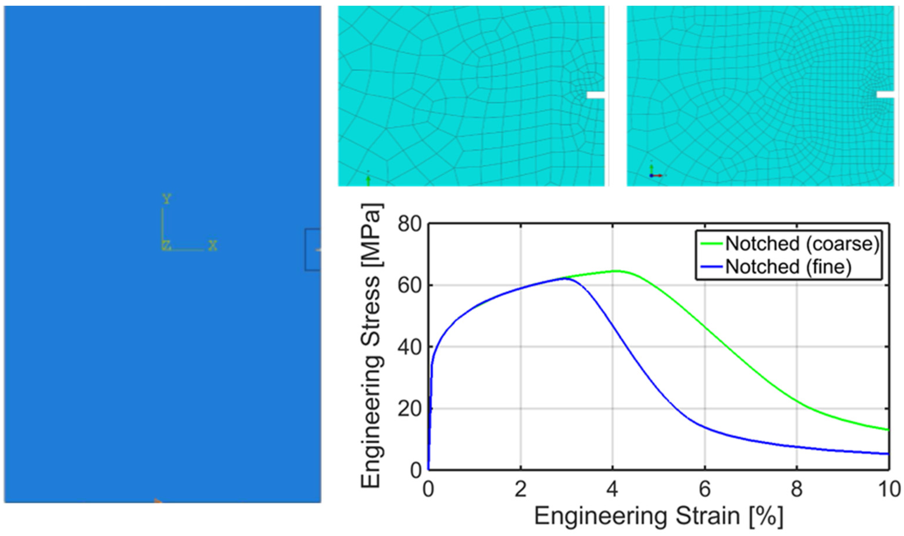
An aluminum sample (15 mm wide and 24 mm long) embedding a small side crack (100 μm wide and 250 μm long) has been analyzed. Plane stress FE simulation of the uniaxial tensile test has been performed, with the load acting in the direction orthogonal to the crack length. Constitutive softening has been ruled out. The mesh has been differently refined in the region surrounding the imperfection as shown in
Figure 8. The corresponding nominal stress
versus nominal strain curves are also visualized in
Figure 8. The numerical analyses evidence the decrease of the applied load for increasing overall displacements due the localization of the plastic deformation in a thin band and of the corresponding reduction of the cross section of the foil. Notice that the nominal stress reaches its maximum (
i.e., the apparent strength) at about 3%–4% elongation.
Figure 8.
Simulation models of an aluminum region embedding a side crack subjected to uniaxial loading and the resulting nominal stress versus nominal strain relationship.
Figure 8.
Simulation models of an aluminum region embedding a side crack subjected to uniaxial loading and the resulting nominal stress versus nominal strain relationship.
The graphs in
Figure 8 are consistent with most experimental observations although, in this case, the onset of the softening branch and the scatter of the apparent failure strain are consequences of the discretization. Similar results can be achieved even in the absence of notches, due to the inhomogeneous stress distribution induced in relatively short specimens by the clamped sides, which prevent the local lateral contraction, and/or by an inaccurate layout of the sample, for instance due to a small misalignment with respect to the loading direction.
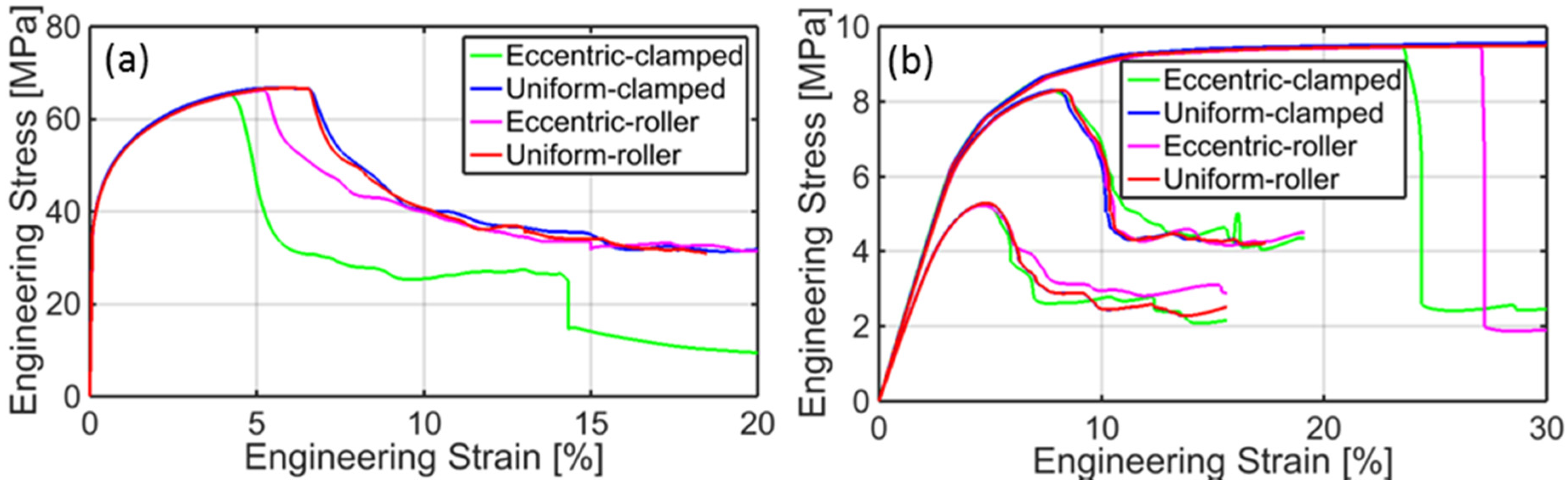
Figure 9a reports the main results of further FE analyses carried out on aluminum samples considering these imperfection sources.
Figure 9.
Nominal stress versus nominal strain relationship resulting from the simulation of tensile tests concerning: (a) plain aluminum; (b) notched polyethylene.
Figure 9.
Nominal stress versus nominal strain relationship resulting from the simulation of tensile tests concerning: (a) plain aluminum; (b) notched polyethylene.
Strain localization can be observed also in polyethylene but at much larger elongation values. The graphs in
Figure 9b concern the simulation of uniaxial tensile tests performed on plain or notched samples similar to those investigated in [
5]. The presence of a centered cut is considered in this case, with crack length equal to about 15% and 50% of the specimen width. The numerical results, which closely resemble the experimental output reported in [
5], show that the effect of small imperfections is practically negligible in the case of the strong stress concentration induced by large notches.
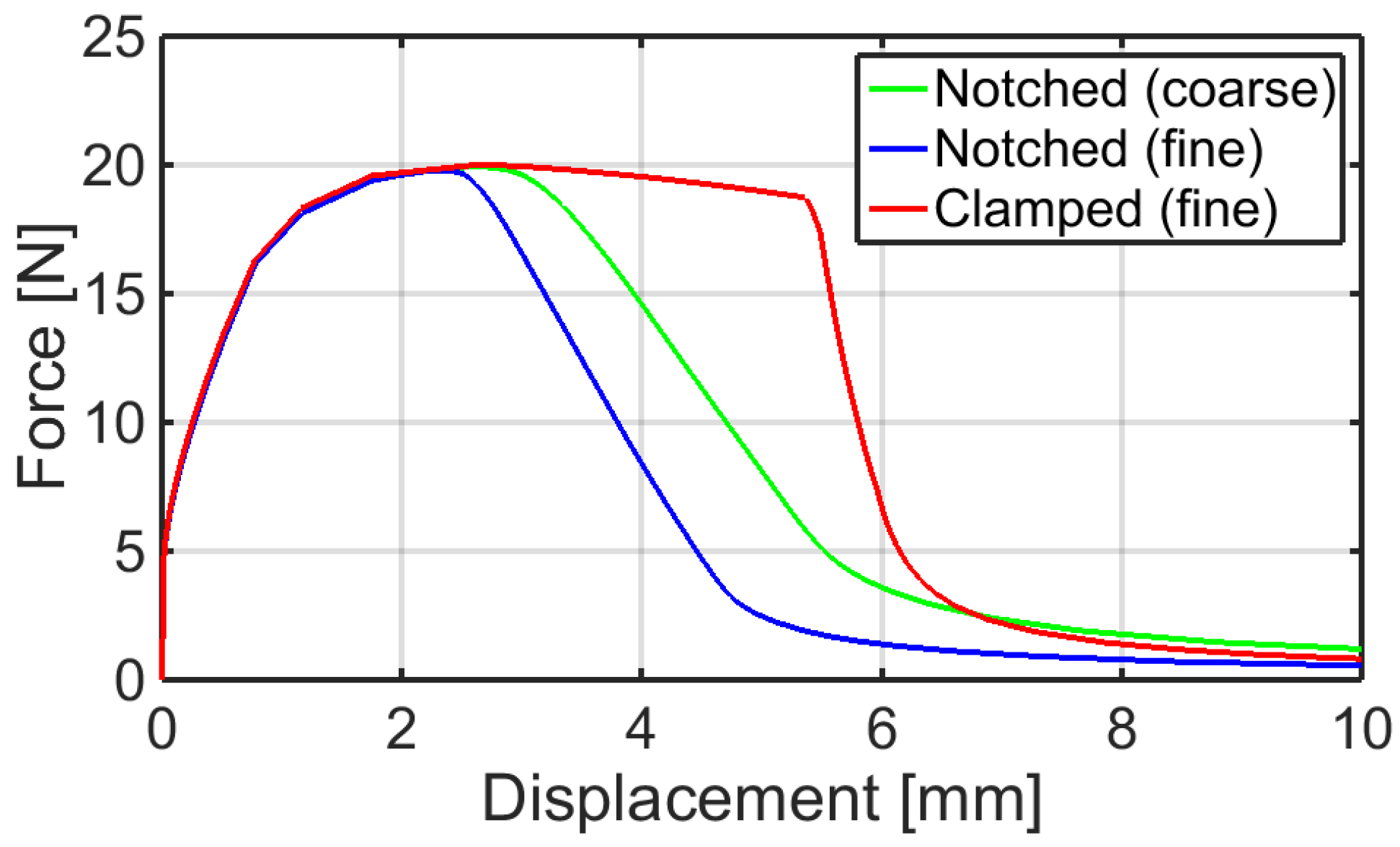
The effect of the constitutive assumptions on the predicted mechanical response of the aluminum laminate have been also investigated. In a further simulation model, the aluminum foil represented in
Figure 8 has been coupled with a similarly discretized polyethylene layer, with no embedded imperfection. Perfect adhesion is assumed. Thus, the polymeric film ties the small crack in the aluminum side.
The resulting overall force-displacement curves, shown in
Figure 10, can be easily compared with the experimental output reported in
Figure 4b. In particular, the nominal strength of the simulated material system is achieved for 2–3 mm elongation values, as it appears in the graphs of
Figure 4. Notice that the pronounced scatter observed in the case of the free-standing aluminum foil, and associated to the discretization, is mitigated by the effect of the polyethylene film. However, also notice that strain localization is not prevented but is transferred from the aluminum foil to the polyethylene layer by the adhesion between these components, differently from what happens in apparently similar material systems exploited in flexible electronics [
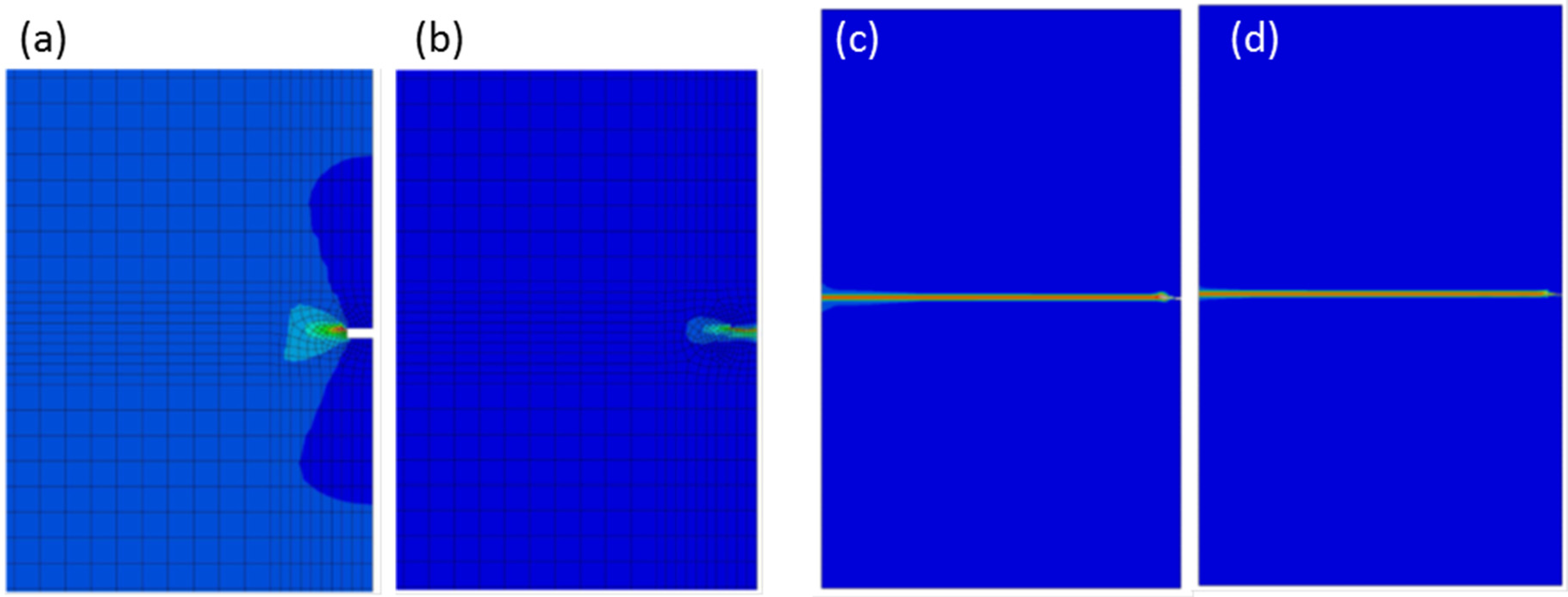
9]. The distribution and evolution of the equivalent plastic strains is represented in
Figure 11.
Figure 10.
Overall load-displacement curves resulting from the simulation of uniaxial tensile tests of aluminum laminates in the hypothesis of perfect adhesion among the components.
Figure 10.
Overall load-displacement curves resulting from the simulation of uniaxial tensile tests of aluminum laminates in the hypothesis of perfect adhesion among the components.
Figure 11.
Distribution of the equivalent plastic strain in: the region around the aluminum crack visualized in
Figure 8 at the maximum load, in the aluminum foil (
a) and in the polyethylene film (
b); in the whole specimen at the maximum elongation, in the aluminum foil (
c) and in the polyethylene film (
d).
The graphs drawn in
Figure 10 show that the geometrical effects dominate the system response also in the absence of notches, for instance, in the case of the stress inhomogeneity induced by clamped sides. Synergetic interaction between these imperfections are then expected in a real experimental situation.


