Article

Olivine-Based Blended Compounds as Positive Electrodes for Lithium Batteries

1
PHENIX, UMR 8234, Sorbonne Universités, Univ. Pierre et Marie Curie, Paris-6, 4 Place Jussieu, 75005 Paris, France
2
IMPMC, Sorbonne Universités, Univ. Pierre et Marie Curie, Paris-6, 4 Place Jussieu, 75005 Paris, France
3
Energy Storage and Conversion, Research Institute of Hydro-Québec, Varennes, QC J3X 1S1, Canada
*
Author to whom correspondence should be addressed.
Inorganics 2016, 4(2), 17; https://doi.org/10.3390/inorganics4020017
Submission received: 15 April 2016 / Revised: 23 May 2016 / Accepted: 24 May 2016 / Published: 31 May 2016

Abstract

:
Blended cathode materials made by mixing LiFePO4 (LFP) with LiMnPO4 (LMP) or LiNi1/3Mn1/3Co1/3O2 (NMC) that exhibit either high specific energy and high rate capability were investigated. The layered blend LMP–LFP and the physically mixed blend NMC–LFP are evaluated in terms of particle morphology and electrochemical performance. Results indicate that the LMP–LFP (66:33) blend has a better discharge rate than the LiMn1−yFeyPO4 with the same composition (y = 0.33), and NMC–LFP (70:30) delivers a remarkable stable capacity over 125 cycles. Finally, in situ voltage measurement methods were applied for the evaluation of the phase evolution of blended cathodes and gradual changes in cell behavior upon cycling. We also discuss through these examples the promising development of blends as future electrodes for new generations of Li-ion batteries.

Graphical Abstract

1. Introduction

Recent advances to develop highly effective electrode materials for Li-ion batteries (LIBs) derived from composites or blended architectures are new technological approaches to designing high-energy and high-power density storage systems [1,2]. The blend electrode is an active material formed by a mixture of two or more distinct lithium insertion compounds that possess percolating frameworks for ions and electrons to achieve better balanced electrochemical performance than that of an individual compound. We can consider four configurations: a complete physical mixture, a segregated blend, a layered-type blend and an integrated blend cathode (Figure 1). Sometimes, the notion of a blend is restricted to the case of physical mixture, but the notion in the present work is extended to all the configurations, including another one, the core-shell structure, where one of the components is the core and the other one is the shell of a particle. For materials currently used as positive electrodes in lithium batteries, the different crystal chemistries are examined from the basic reaction driven by a charge transfer from the guest Li+ ions to the conduction band of the host compound. Thus, electron-donating species of a blend electrode composed of two components—(Mn1X)1 and (Mn2X)2 (where M is a transition metal with oxidation state ni, and X is an anion) host components—can give rise to a reversible reaction classically represented by the following scheme:
xLi+ + xe + (Mn1X)1 + (Mn2X)2 ↔ [Lix1+(Mn1−x1X)1] + [Lix2+(Mn2−x2X)2].
In the usual case, xi is the molar lithium insertion fraction, and [Lixi+(Mn,ix,iX)i] is the final product. The concept of using two or more electrochemically active materials in a blend matrix is not new; since 1976, Margalit suggested applying xAg3PO4·(1−x)Ag2CrO4 to a Li primary battery for pacemakers and watches [3]. This concept has been extended to numerous cathode materials to avoid their individual drawbacks [4,5,6,7]. Pynenburg et al. [4] patented a rechargeable lithium cell composed of a physical mixture of spinel LixMn2O4 and one of the lithiated metal oxides from the LixMO2 group (M = Ni, Co), wherein 0 < x ≤ 2. For instance, pure LiMn2O4 has a better rate capability than pure LiNi0.8Co0.15Al0.05O2, but, at a low rate, the specific energy of LiNi0.8Co0.15Al0.05O2 is higher than that of LiMn2O4, so that mixing the two elements should lead to an optimized compromise [5,7]. Other effects not necessarily expected have been observed. Numata et al. [5] showed the advantages of blending Li1+xMn2−xO4·LiNi0.8Co0.15Al0.05O2, which decreased the Mn dissolution from the spinel into the electrolyte. Meanwhile, however, it increased the irreversible capacity loss in the first cycle and deteriorated the rate capability. Albertus et al. [7] adopted a mathematical model to multiple types of active materials in a single electrode to treat both direct (galvanostatic) and alternating (impedance) currents and concluded that combining a sloped-potential system (LiNi0.8Co0.15Al0.05O2) with a flat-potential system (LiMn2O4) may assist in electrode state-of-charge (SOC) determination. In 2011, LIBs (composed of 288 Li-ion cells) using a blended cathode formed by the mixture LiMn2O4·LiNixMnyCo1−xyO2 were developed by LG Chem. Ltd. and applied to power the GM Chevy-Volt electric vehicles [8]. In 2006, Kim et al. [6] studied the 0.5LiCoO2·0.5LiNi1/3Mn1/3Co1/3O2 (LCO–NMC)-mixed cathode exhibiting a stable cycleability maintained at ca. 163 mAh·g−1.
Depending on the nature and the combination of materials, the blending found different advantages (but not all of them at the same time), such as (i) the inhibition of overheating effects during overcharge conditions; (ii) a reduction in irreversible capacity decay; (iii) an improvement of cycling life; (iv) a rise of the discharge C-rate; and (v) endurance of high temperature and thermal stability [9,10,11,12].
The literature of olivine-based blended active cathode materials is rather sparse. The good thermal stability of olivine-structured compounds LiMPO4 (M = Fe, Mn) makes them attractive cathode materials, but the relatively flat voltage plateau at 3.45 V vs. Li0/Li+ is a limitation, which yields difficult the SOC evaluation. This drawback can be overcome using a blend of olivine with a layered material. Various mixtures have been tested such as the blend of LiFePO4 (LFP) with Li-rich NMC [13,14], which exhibits improved power capability, thermal stability, and easy SOC monitoring. In another approach, a blend of LiFePO4 with Li3V2(PO4)3 (LVP) delivers lower capacity and has a voltage profile consisting of multiple plateaus due to the LVP component [15]. Uniform blends of micron-sized LiMn2O4 with nano-sized LiFePO4 (1:1 mass ratio) prepared by ball milling showed that LFP powders not only cover the LiMn2O4 particles but also effectively fill the cavity of the spinel network [16]. Recently, blend electrodes were prepared by mixing the olivine LiFe0.3Mn0.7PO4 (LFMP) and LiMn1.9Al0.1O4 spinel (LMO) in order to obtain a composite electrode, combining the high capacity of LFMP and the rate capability of the spinel [17].
In this paper, we discuss the architecture, the structural properties, and the electrochemical performance of two LiFePO4-based blend systems as positive electrodes for lithium batteries: (i) the blend fabricated by LiFePO4 with LiMnPO4 (LMP) olivine structures, and (ii) the blend formed by the LiFePO4 olivine structure with the LiNi0.33Mn0.33Co0.33O2-layered compound. In both systems, the use of carbon-coated LFP results in an increase in electrode conductivity and rate capability. Thus, we show that blending may be a good solution to avoid individual drawbacks of components.

2. Results

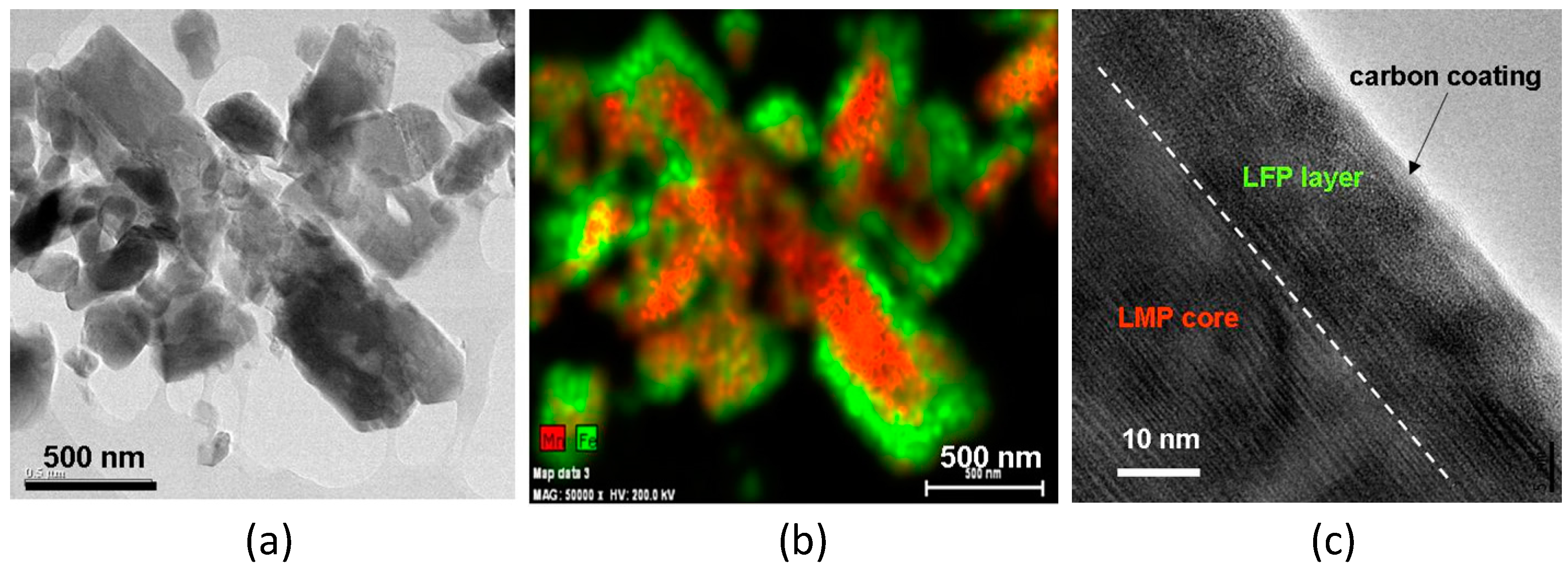
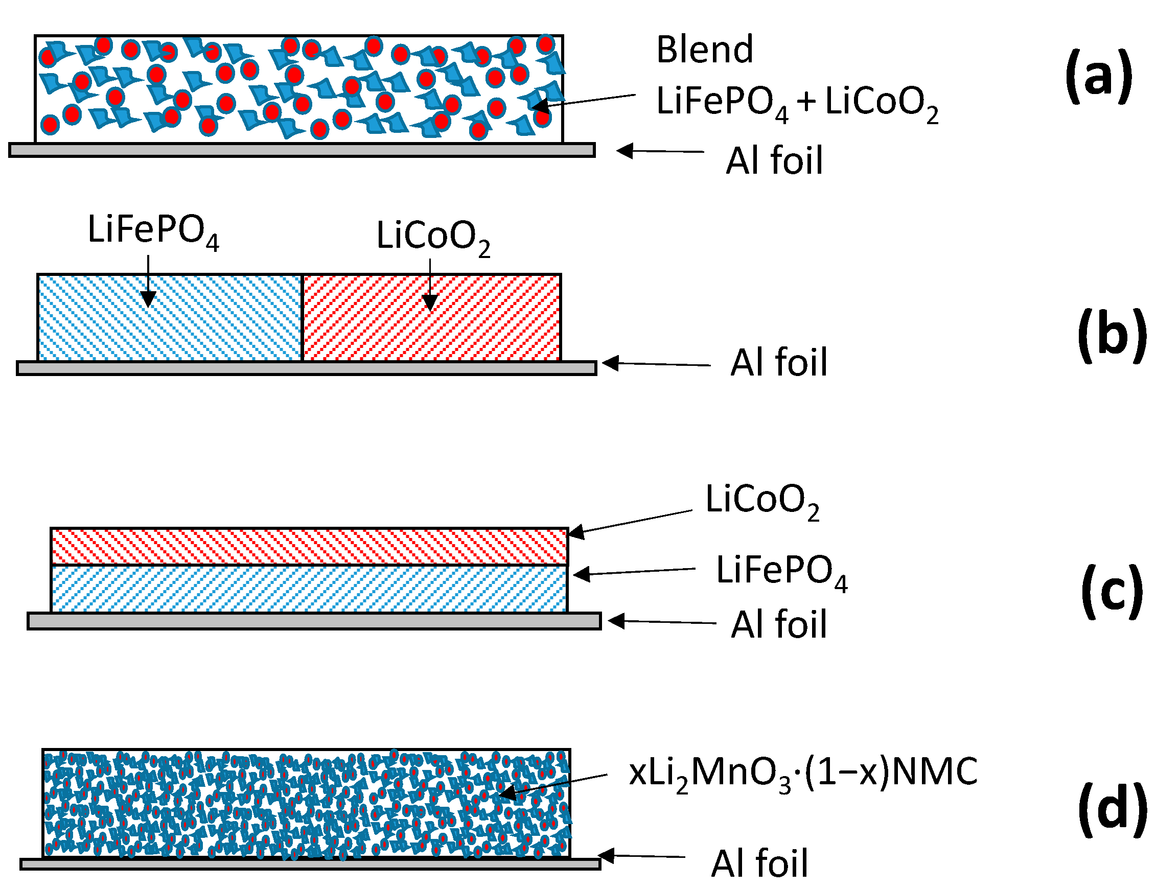
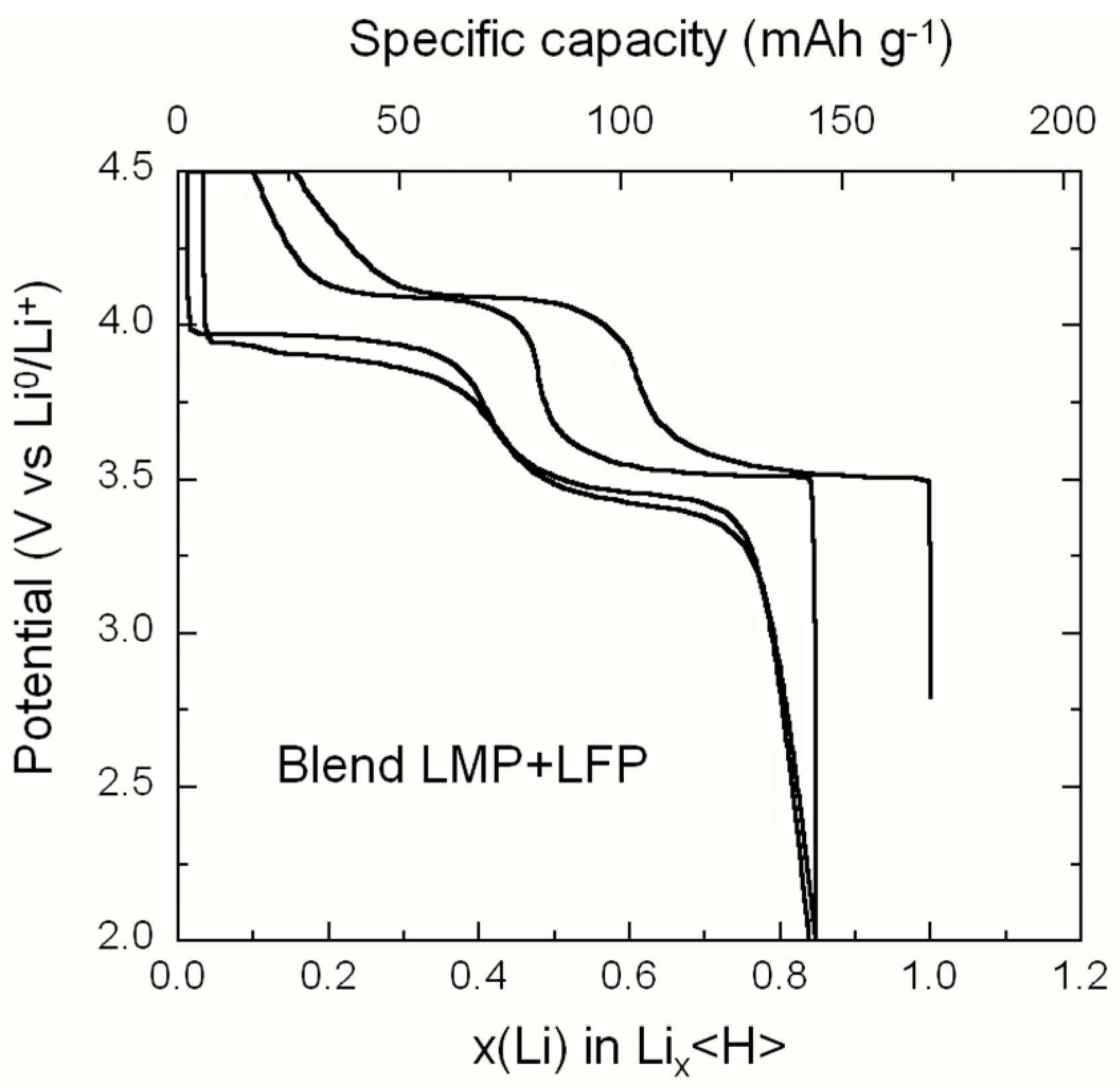
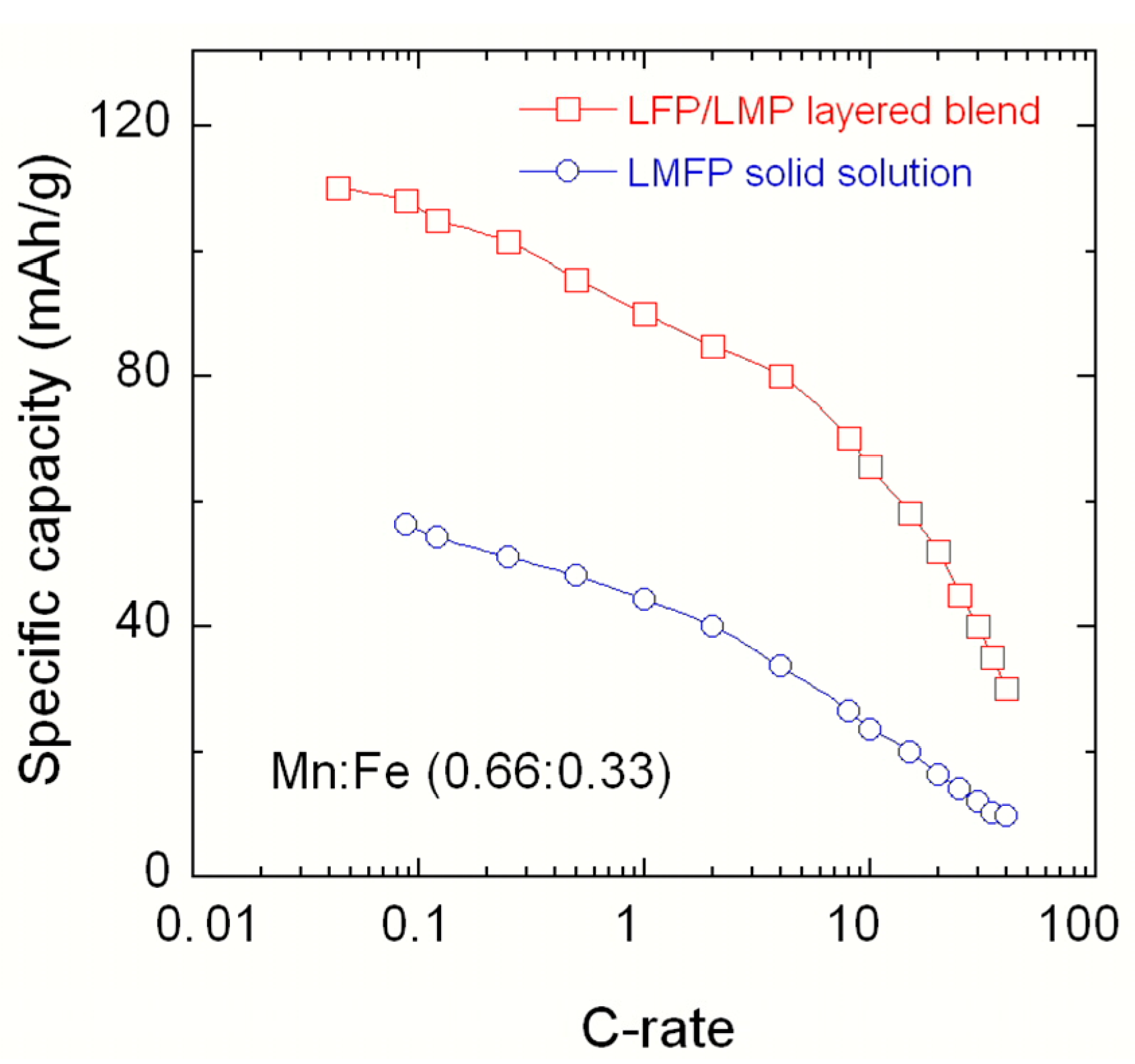
2.1. LiMnPO4–LiFePO4 (LMP–LFP) Blended Electrode

To overcome the difficulty of carbon coating on LiMnPO4 (LMP) olivine particles, it is possible to prepare a LiMnPO4–LiFePO4 (LMP–LFP) composite, in which the carbon-coated LFP component encapsulates the core of LiMnPO4 particles to take advantage of the catalytic reaction of Fe with C. The STEM images of several particles representative of the sample are shown in Figure 2. Figure 2a displays well-crystallized flaky grains several tens to 100 nm in size. Some of the grains have with many dislocations. A typical EDX map (Figure 2b) shows the two components of blended particles: LMP (in red) in the center, surrounded with a LFP layer (in green). Elemental analysis indicates the LMP–LFP (66:33) composition. The Fe content is minimal at the center and maximal at the surface, while the opposite holds true for the Mn content. The HRTEM image (Figure 2c) shows the lattice fringes with the sharp interface between LiMnPO4 and LiFePO4 and the continuous carbon-coating layer (~2–3 nm thick). To summarize the results illustrated by the structural analysis, LFP forms a continuous layer that partly covers most of the LMP particles, but it also forms few small LiFePO4 particles distributed sparsely (Figure 2). The strain at the interface between the two materials is accommodated by extended defects such as dislocations and grain boundaries; on the other hand, the LFP layer is well crystallized as evidenced by the lattice fringes in the HRTEM image (Figure 2c). This result suggests that LFP is deposited by some epitaxial effect on the well-crystallized surface of LMP, since the free surface of LFP at 600 °C is disordered [18].
The electrochemical features of the LMP–LFP (66:33) blend is illustrated in Figure 3, showing the charge–discharge profiles vs. specific capacity of the Li//blend coin cell for the first two cycles. Electrochemical tests were carried out at C/12 in the potential range 2.0–4.5 V vs. Li0/Li+. The upper flat part corresponds to the limit of 4.5 V imposed on the potential to protect the electrolyte. The first plateau observed at 3.5 V is characteristic of the Fe2+/Fe3+ redox potential vs. Li in LiFePO4. The next plateau at 4.0 V is characteristic of the Mn2+/Mn3+ potential in LiMnPO4, so that both components efficiently contribute to the electrochemical properties. We find that the specific capacity of the first charge is 144 mAh·g−1 (charge transfer of x = 0.86e) followed by the discharge/charge ratio close to unity at the second cycle. Using such a blended electrode, the electrochemical properties are improved with respect to the carbon-coated LiMn2/3Fe1/3PO4 solid solution with a comparable Fe/Mn ratio, as shown in Figure 4. The Peukert plots show that, at 10C, the delivered capacity of the blend is 65.5 mAh·g−1 against 23.5 mAh·g−1 for LiMn2/3Fe1/3PO4. Therefore, the use of a LiFePO4 as a buffer layer between the high-density cathode element (like LiMnPO4) and the carbon layer opens a new route to improve the performance of the olivine family as the active element of the cathode for Li-ion batteries. This result is attributable to the fact that the LFP shell allows for the coating of the composite, while it is difficult to deposit the carbon at the surface of LMP at a temperature small enough to avoid its decomposition (≈650 °C).

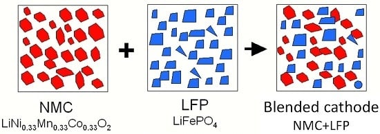
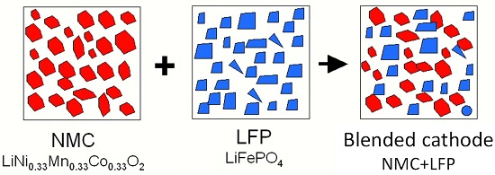
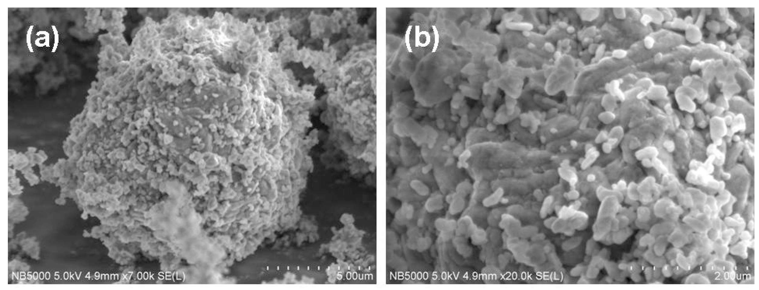
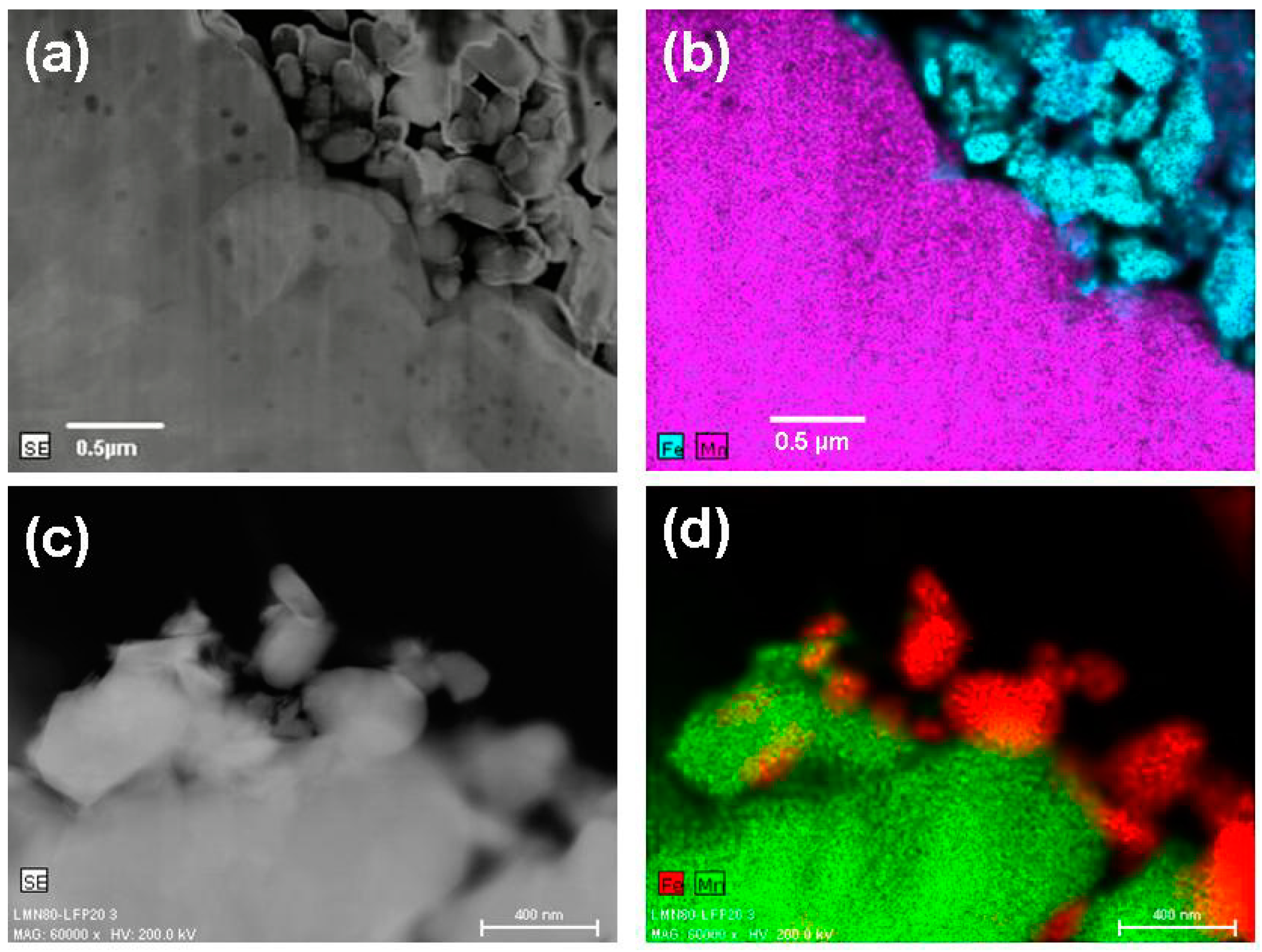
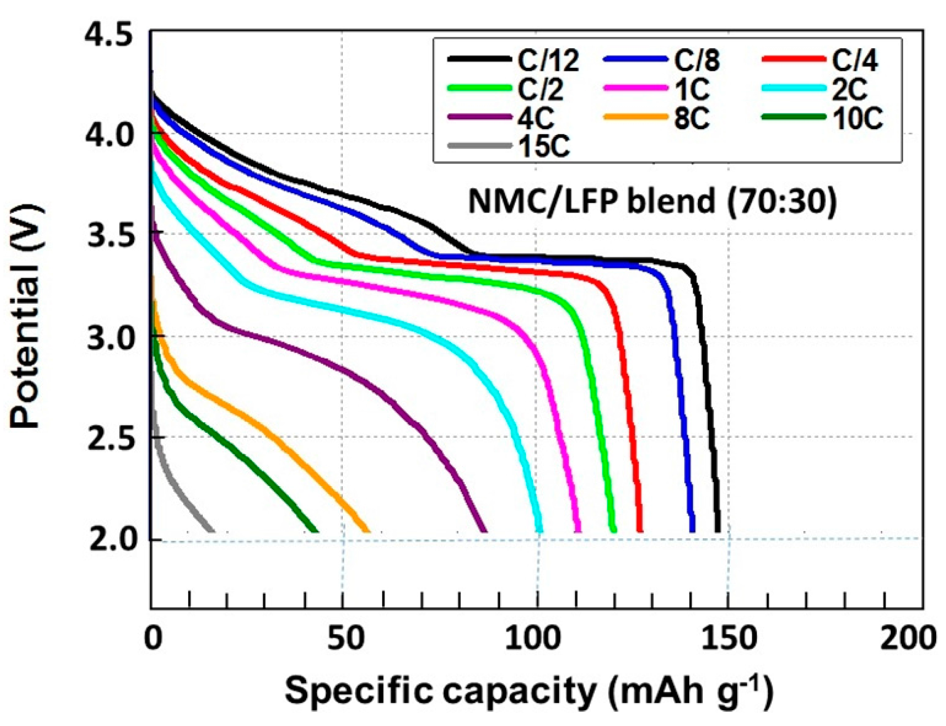
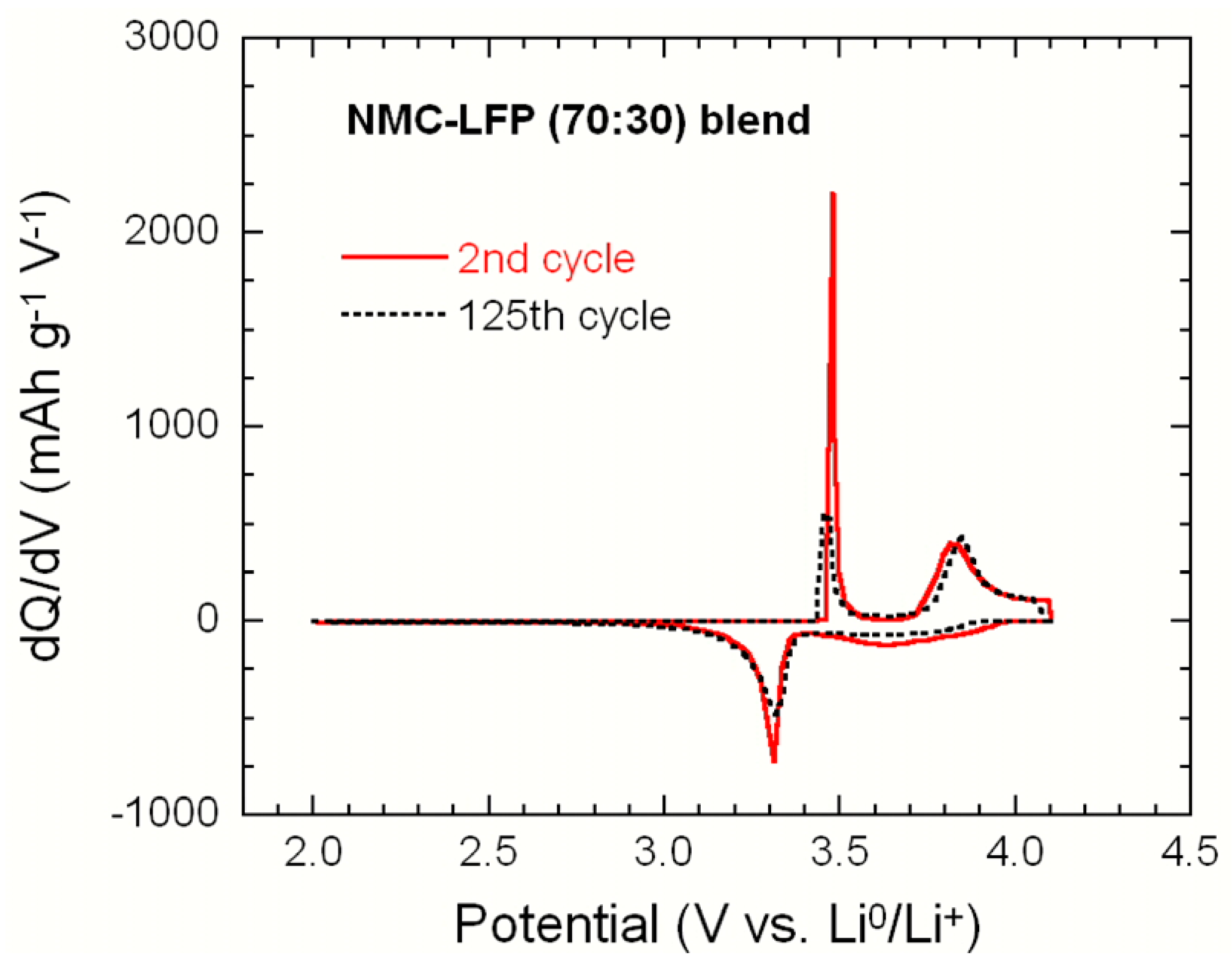
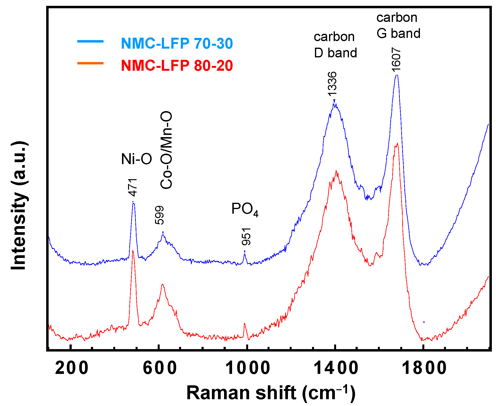
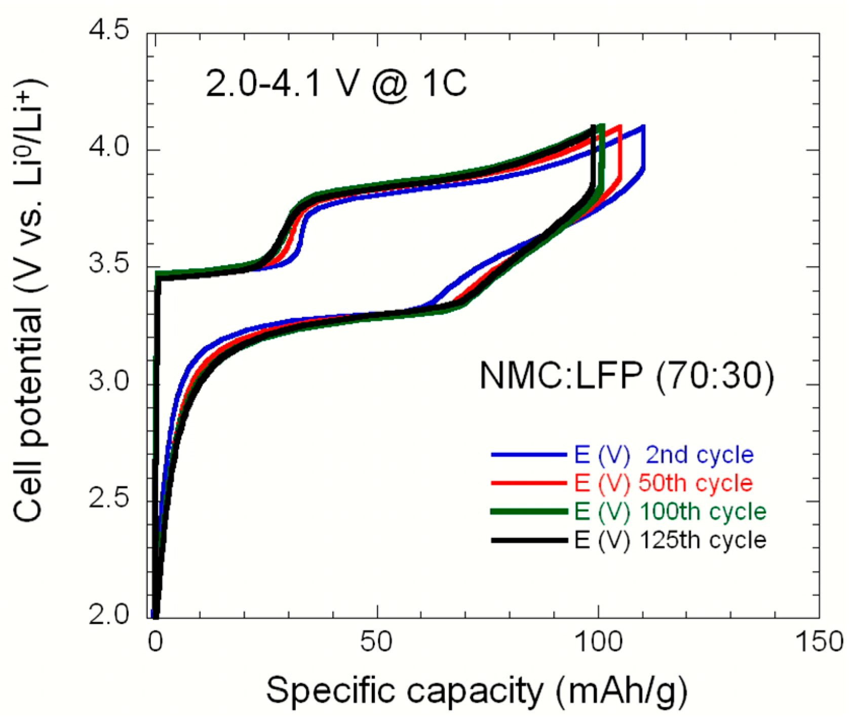
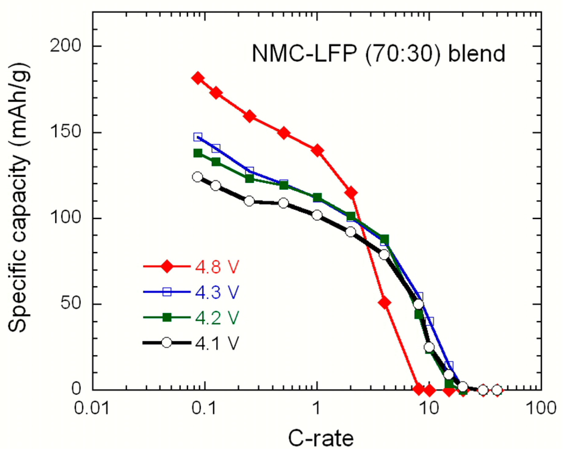
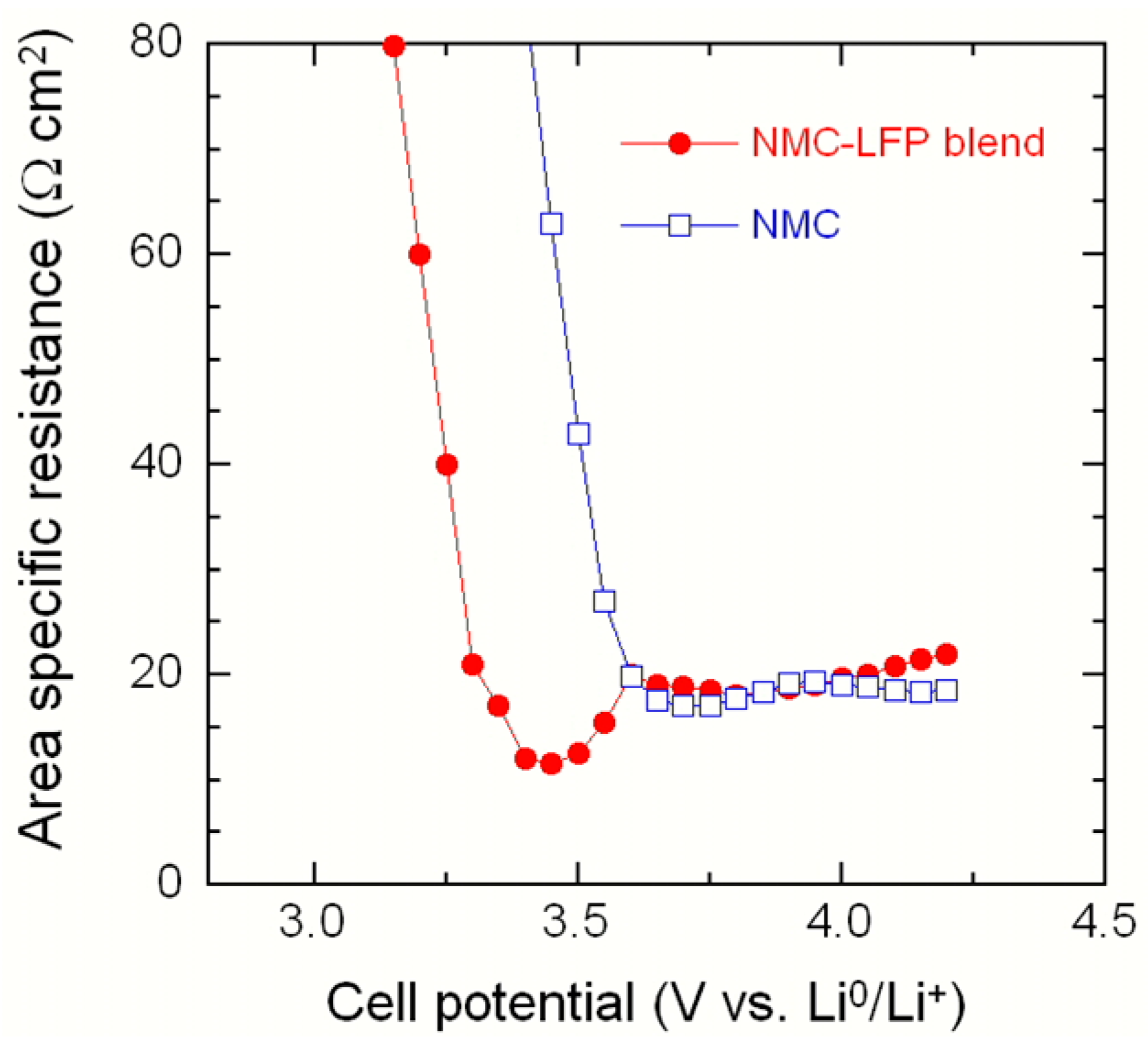
2.2. LiNi1/3Mn1/3Co1/3O2–LiFePO4 (NMC–LFP) Blended Electrode

A blended cathode formed by the LiNi1/3Mn1/3Co1/3O2–LiFePO4 (NMC–LFP) mixture exhibits excellent rate capability by using nano-sized LFP particles and delivers higher capacity, i.e., 180 mAh·g−1, due to the NMC component. Consequently, a Li-ion battery including NMC–LFP physical blending provides a good solution that achieves both energy and power capability and exhibits improved electrochemical features with thermal stability similar to LFP. In the SEM images of the NMC–LFP (70:30) blend shown in Figure 5, one discerns the two distinct components of this blend. The cathode material prepared by ultra-microtomy exhibits large spherically shaped NMC particles (secondary particles ~10 µm in size, having a very close size distribution) and small LFP nano-sized particles (<0.5 µm), but no LFP coating on NMC is observed. This could be due to the mechanical force applied during the microtomy. Figure 6 shows the TEM images and EDX maps of NMC–LFP blends with different compositions: (a) (70:30) with Fe in blue, Mn in violet and (b) (80:20) with Fe in red, Mn in green. The differences in morphology and particle size between the two samples are evidenced. Higher SEM magnification confirms that the co-grounded blend sample possesses a better coverage of NMC with LFP than the (80:20) sample.
The structural properties of the NMC–LFP blends were studied by Raman spectroscopy as shown in Figure 7. A typical Raman spectrum displays three sets of bands: (i) the vibrational features of NMC with Ni–O mode at 471 cm−1 and the broad band at ca. 600 cm−1 attributed to the Co–O/Mn–O stretching modes [19]; (ii) the symmetric stretching vibration of PO43− molecular units of LiFePO4 at around 950 cm−1; and (iii) two broad Raman bands of the carbon surrounding the LFP particles centered at 1336 and 1607 cm−1 assigned to the D- and G-bands, respectively. Note that the high intensity of the latter bands is due to the strong Raman scattering efficiency of carbon [20].
Figure 8 shows the discharge profiles (5th cycle) as a function of the C-rate for a Li-coin cell with the NMC–LFP (70:30) blend as positive electrode. Electrochemical tests were carried out in the potential range 2.0–4.2 V vs. Li0/Li+. The shape of the curves shows combined features of LFP with the potential plateau at 3.35 V and the sloppy profile of the NMC component from 3.4 to 4.2 V (see discussion below). This behavior suggests the independent charge–discharge profiles of the cathode constituents. The discharge capacity is 148 mAh·g−1 at C/12 rate and 42 mAh·g−1 at 10C. Note that, as some Li+ ions are not removed from NMC at 4.2-V cut-off voltages, this causes a lower specific capacity. The electrochemical performance of a Li-coin cell with the NMC–LFP (70:30) blend positive electrode as a function of the number of cycles at 1C rate (Figure 9) shows that this cathode material exhibits very stable cycleability after 125 cycles.
The Peukert plots of the NMC–LFP (70:30) blended electrode cycled at different cut-off voltages are shown in Figure 10. These results indicate that (i) the 4.8-V cut-off provides the higher specific capacity of 180 mAh·g−1 at a C/10 rate, but shows the lowest performance at high rates; (ii) higher capacity was obtained when the voltage cut-off was higher than 4.1, 4.2, and 4.3 V; and (iii) for the 4.1-V cut-off, the capacity fade is less pronounced, i.e., 0.12 mAh·g−1 per cycle. The impedance measurements, after formation cycles, show an increase in the charge transfer resistance at a voltage cut-off of 4.8 V, and a comparable result is observed with 4.1 and 4.3 V cut-off. As pointed out by Imachi et al. [12], who investigated a double-layered LiCoO2·LiFePO4 blended cathode, the advantage of blending LFP consists in the creation a resistive barrier that improves the tolerance against overcharging the electrochemical cell.

3. Phase Evolution

In situ voltage measurement methods have been applied for the evaluation of the phase evolution of blended cathodes and gradual changes in cell behavior upon cycling. Using the so-called incremental capacity (IC) with respect to cell potential, dQ/dV = f(V), and the differential voltage curve dV/dQ = f(Q) could provide such information, since voltage plateaus in the V–Q profile is identifiable by dQ/dV peaks on IC curves [21,22].
Figure 11 presents the incremental capacity vs. potential for the Li coin cell with the NMC–LFP (70:30) blend cathode. The peaks in Figure 11 should only relate to the positive electrode material since the negative electrode is lithium metal. The typical IC curves of the blend clearly display two sets of redox peaks, each one related to the NMC or LFP component. The IC of the blend exhibits a sharp peak at 3.47 V corresponding to the voltage plateau of the charge profile Q vs. V due to the Fe2+/Fe3+ oxidation in the LFP component followed by a broad feature at 3.85 V corresponding to the Ni2+/Ni4+ oxidation in the NMC component. The reduction processes occurred at 3.65 and 3.32 V, respectively. The IC curves show that the decrease in the area of the LFP peak at 3.47 V on charge, along with the slight evolution of the peak at 3.32 V on discharge, while the redox NMC peaks are almost unchanged after 125 cycles. These results reveal the possible mechanisms involved in the blend material that could be associated with the strain–stress field interaction in the particles due to the mechanical milling preparation with the net effect of shortening the 3.47-V plateau. Thus, changes in the dQ/dV curves can help to identify ageing of electrode materials [23].
Another typical test to characterize the power capability of a cell at different state of charge (SOC) is the plot of the area specific resistance (ASR) vs. the cell potential defined by the Equation (2):
ASR = V oc V cell I A ,
where Voc is the open-circuit voltage, I the current, and A is the electrode area. As presented in Figure 12, the ASR of the NMC cell drops sharply for potential Vcell < 3.5 V, which is an inherent electrochemical feature of layered oxides, while the ASR of the NMC–LFP blend increases sharply at lower potential, ca. 3.25 V. These results show that the blend cathode can deliver high power at low SOC due to the 3.5-V plateau of the discharge curve of LFP.

4. Discussion

The results we report here enable the evaluation of the blends as new cathodes in a given geometry. This remains to be determined and chosen to optimize the electrochemical performance. In the case of the LMP–LFP blend, the core-shell geometry must be chosen because the purpose is to have a conductive carbon coating layer that could be deposited more efficiently on LFP than on LMP. In the case of NMC–LFP, only the case of mixed powders was investigated. To our knowledge, the only work where the effect of the geometrical distribution of the powders has been investigated is the comparison between the electrochemical properties of cells prepared with positive electrodes made of Li[Li0.17Mn0.58Ni0.25]O2–LFP blend in the completely intermixed, segregated, and layered geometries (see Figure 1) [13]. The discharge profiles are reported in Figure 13 for the case of an equal ratio of the two powders at different C-rates after few initial cycles devoted to the stabilization of the cell and solid-electrolyte interface. The characteristic sloping discharge curve starting above 4 V can be attributed to the Li[Li0.17Mn0.58Ni0.25]O2 part, and the relatively level portion of the curve occurring at less than 3.4 V can be attributed to the carbon-coated LiFePO4. Clearly, the performance of the three electrodes is different. The low-rate capability of Li[Li0.17Mn0.58Ni0.25]O2 lowered overall electrode specific energy when the materials were mixed intimately or layered on top of each other in a single electrode. The best geometry for this blend is thus the segregated case, because it is the only configuration where the current can be driven through the LFP part at a high discharge rate. Otherwise, the active particles of both components must be held at the same potential. On the other hand, if Li[Li0.17Mn0.58Ni0.25]O2 is replaced by LiCoO2, a material with a higher rate capability than Li[Li0.17Mn0.58Ni0.25]O2, the layered cell’s performance will greatly improve. Therefore, more systematic studies of blends as a function of the different geometries should be investigated in the near future.
Another field of investigation that should be developed is the optimization of the mixed powders. In practice, it is very difficult to mix powders. The phenomenon of de-mixing has been well-known for a long time [24]. In practice, the sizes of the particles of the components of the blend are different, in which case “size-segregation” may occur. This phenomenon is made possible by the gaps that open up around particles when they are shaken, allowing percolation to occur. Large particles tend to move toward less dense regions of smaller particles, so that large objects can rise to the top of vertically shaken layers, a well-known effect in granular materials. In addition, the particles can also spontaneously form patterns in the process [25]. The properties of mixed powders then depend on different parameters: the shape and size of the particles of the two blend elements, the packing structure of the powder mixtures in the scale of particle contacts (coordination number of each powder, defined as the number of particles surrounding and having contact with a reference particle), and the distribution of the contact chains, which, in the present case, also determines the electrical resistance of the blend. So far, the development of powder dynamics has been investigated in the framework of vibrations and flow. In the context of blends for electrodes, the dynamics is associated with the volume change of the particles induced by the lithium insertion of or de-insertion upon cycling, which is a new area of research to be developed in the near future.

5. Materials and Methods

5.1. Synthesis and Characterizations

The synthesis procedure of the LMP–LFP composite consists of three steps: (i) LiMnPO4 olivine was synthesized by the hydrothermal method assisted with ascorbic acid (1.3 g·L−1) and 3% Denka black using LiOH·H2O, MnSO4·H2O, and H3PO4 (Li:Mn:P molar ratio 3:1:1) as raw materials; (ii) As-prepared LMP powders were added to the LFP precursor solution made by the dissolution of LiOH·H2O, FeSO4·7H2O, and (NH4)2HPO4 in distilled water. The reactive medium thus obtained is poured into a polytetrafluoroethylene (PTFE) vessel, put into a stainless steel chamber (Parr, Volume = 325 mL), and heated at 220 °C for 7 h. After cooling at room temperature, the powder is obtained by filtration, washed three times in distilled water, and dried at 90 °C during 12 h in N2 atmosphere. At the end, 15.1 g of LMP–LFP blended material was obtained; (iii) The carbon-coating of the composite was obtained by mixing the product of step (ii) with a solution of lactose, the ratio lactose/composite being 1/10. This product was heated at 400 °C for one hour, then heated at 600 °C for 3 h [26].
LiNi0.33Mn0.33Co0.33O2-layered powders were prepared using the co-precipitation method described elsewhere [27] by a hydroxide route, for which transition-metal hydroxide and lithium carbonate were starting materials. Using a lithium excess η = Li/M ratio of 1.05 the sample shows low cationic mixing Ni2+(3b) < 2%. The composite was obtained by physical mixing of NMC with carbon-coated LFP using a ball milling technique with different weights (70:30) and (20:80) ratios (NMC:LFP).
The characterization of the samples was done using a Hitachi HD-2700C dedicated STEM with a CEOS aberration corrector and a cold field-emission gun equipped with a newly designed silicon-drift detector (SDD) from Bruker (East Milton, ON, Canada), which offers over 10 times the solid angle of conventional energy-dispersive X-ray Si(Li) detectors. This dedicated STEM has demonstrated an image resolution of 78 pm in high angle annular dark field (HAADF).

5.2. Electrochemical Tests

Electrochemical tests were performed with composite electrode materials prepared by mixing 80% (w/w) of the active material, 10% (w/w) super C65 carbon (TIMCAL, Willebroek, Belgium), and 10% (w/w) polyvinylidene fluoride (Solef PVdF 6020 binder, Solvay, Brussels, Belgium) in N-methyl-2-pyrrolidone (NMP, Sigma-Aldrich, St. Louis, MO, USA) to produce a slurry. A 90-µm-thick film was obtained by coating this slurry on aluminum foil that gives an electrode loading ~8 mg·cm−2. This film was dried overnight at 80 °C, and then punched out with a diameter of 1.4 cm. The cell was assembled as coin-type cells in an argon-filled glove box using lithium foil (Alfa Aesar, Ward Hill, MA, USA) as an anode, LP30 (1 mol·L−1 LiPF6 in (1:1) ethylene carbonate (EC)—dimethyl carbonate (DMC) as an electrolyte, and glass microfiber filters (Whatmann®-GF/D 70 mm Ø, Sigma-Aldrich) as a separator. VMP3 multi-channel potentiostat (Bio-Logic, Claix, France) was used to electrochemically characterize the electrodes at 25 °C in the voltage range of 1.5–4.8 V vs. Li0/Li+ in galvanostatic tests.

6. Conclusions

In this paper, we studied two blended cathode materials based on a mixture of nano-structured particles of LiFePO4 olivine with another micro-structured insertion compounds such as LiMnPO4 olivine and LiNi1/3Mn1/3Co1/3O2-layered compound. To overcome the difficulty of carbon coating on LiMnPO4 olivine particles, the preparation of the LMP–LFP (66:33) composite was realized. Using such a blended electrode, the electrochemical properties are improved with respect to the carbon-coated LiMn2/3Fe1/3PO4 solid solution with a comparable Fe/Mn ratio. The blended cathode formed by the NMC–LFP mixture exhibits excellent rate capability by using nano-sized LFP particles and delivers a higher capacity, i.e., 180 mAh·g−1, due to the NMC component. Consequently, Li-ion batteries including NMC–LFP physical blending provide a good solution that achieves both energy and power capability and exhibits improved electrochemical features with thermal stability similar to LFP.
In situ voltage measurement methods were applied for the evaluation of the phase evolution of blended cathodes and gradual changes in cell behavior upon cycling using the so-called incremental capacity (IC) with respect to cell potential, dQ/dV = f(V). Another typical test to characterize the power capability of a cell at different states of charge (SOCs) is the plot of the area specific resistance (ASR) vs. the cell potential. Both methods have demonstrated that blending cathode materials with LiFePO4 nano-particles improves their electrochemical performance. We hope that the electrochemistry will lean on the progress that has been made in mathematics to model non-linear dynamics of powder mixing and will benefit from the powder technology sustained by their application in different fields of the industry in the near future, aiming to optimize the blends to be used as new electrodes of Li-ion batteries.

Acknowledgments

This study was supported by the Laboratoire Physicochimie des Electrolytes et Nanosystems Interfaciaux, Université Pierre et Marie Curie, Paris.

Author Contributions

Christian M. Julien and Alain Mauger conceived and wrote the paper, Karim Zaghib designed the experiments; Julie Trottier, Pierre Hovington and Henri Groult assisted characterization of the materials.

Conflicts of Interest

The authors declare no conflict of interest.

References

  1. Chikkannanavar, S.B.; Bernardi, D.M.; Liu, L. A review of blended cathode materials for use in Li-ion batteries. J. Power Sources 2014, 248, 91–100. [Google Scholar] [CrossRef]
  2. Zaghib, K.; Trudeau, M.; Guerfi, A.; Trottier, J.; Mauger, A.; Julien, C.M. New advanced cathode material: LiMnPO4 encapsulated with LiFePO4. J. Power Sources 2012, 204, 177–181. [Google Scholar] [CrossRef]
  3. Margalit, N. Non-Aqueous Primary Battery Having a Blended Cathode Active Material. U.S. Patent 3,981,748, 21 September 1976. [Google Scholar]
  4. Pynenburg, R.; Barker, J. Cathode-Active Material Blends of LixMn2O4. U.S. Patent 5,429,890, 4 July 1995. [Google Scholar]
  5. Numata, T.; Amemiya, C.; Kumeuchi, T.; Shirakata, M.; Yonezawa, M. Advantages of blending LiNi0.8Co0.2O2 into Li1+xMn2−xO4 cathodes. J. Power Sources 2001, 97–98, 358–360. [Google Scholar] [CrossRef]
  6. Kim, H.S.; Kim, S.I.; Kim, W.S. A study on electrochemical characteristics of LiCoO2/LiNi1/3Mn1/3Co1/3O2 mixed cathode for Li secondary battery. Electrochim. Acta 2006, 52, 1457–1461. [Google Scholar] [CrossRef]
  7. Albertus, P.; Christensen, J.; Newman, J. Experiments on and modeling of positive electrode with multiple active materials for lithium-ion batteries. J. Electrochem. Soc. 2009, 156, A606–A618. [Google Scholar] [CrossRef]
  8. GM’s new battery chemistry? It’s already in Chevy Volt. Available online: http://www.popsci.com/cars/article/2011-01/gm%e2%80%99s-new-battery-chemistry-it%e2%80%99s-already-chevy-volt (accessed on 7 January 2011).
  9. Tran, H.Y.; Täubert, C.; Fleischhammer, M.; Axmann, P.; Küppers, L.; Wohlfahrt-Mehrens, M. LiMn2O4 spinel/LiNi0.8Co0.15Al0.05O0.2 blends as cathode materials for lithium-ion batteries. J. Electrochem. Soc. 2011, 158, A556–A561. [Google Scholar] [CrossRef]
  10. Gao, J.; Manthiram, A. Eliminating the irreversible capacity loss of high capacity layered Li[Li0.2Ni0.13Mn0.54Co0.13]O2 cathode by blending with other lithium insertion hosts. J. Power Sources 2009, 191, 644–647. [Google Scholar] [CrossRef]
  11. Kitao, H.; Fujihara, T.; Takeda, K.; Nakanishi, N.; Nohma, T. High-temperature storage performance of Li-ion batteries using a mixture of Li–Mn spinel and Li–Ni–Co–Mn oxide as a positive electrode material. Electrochem. Solid State Lett. 2005, 8, A87–A90. [Google Scholar] [CrossRef]
  12. Imachi, N.; Takano, Y.; Fujimoto, H.; Kida, Y.; Fujitami, S. Layered cathode for improving safety of Li-ion batteries. J. Electrochem. Soc. 2007, 154, A412–A416. [Google Scholar] [CrossRef]
  13. Whitacre, J.F.; Zaghib, K.; West, W.C.; Ratnakumar, B.V. Dual active material composite cathode structures for Li-ion batteries. J. Power Sources 2008, 177, 528–536. [Google Scholar] [CrossRef]
  14. Gallagher, K.G.; Kang, S.H.; Park, S.U.; Han, S.Y. xLi2MnO3·(1−x)LiMO2 blended with LiFePO4 to achieve high energy density and pulse power capability. J. Power Sources 2011, 196, 9702–9707. [Google Scholar] [CrossRef]
  15. Zheng, J.C.; Li, X.; Wang, Z.X.; Niu, S.S.; Liu, D.; Wu, L.; Li, L.J.; Li, J.H.; Guo, H.J. Novel synthesis of LiFePO4–Li3V2(PO4)3 composite cathode material by aqueous precipitation and lithiation. J. Power Sources 2010, 195, 2935–2938. [Google Scholar] [CrossRef]
  16. Qiu, C.; Liu, L.; Du, F.; Yang, X.; Wang, C.; Chen, G.; Wei, Y. Electrochemical performance of LiMn2O4/LiFePO4 blend cathodes for lithium ion batteries. Chem. Res. Chin. Univ. 2015, 31, 270–275. [Google Scholar] [CrossRef]
  17. Wohlfahrt-Mehrens, M.; Klein, A.; Axmann, P. Blend Performance of LiMn0.7Fe0.3PO4–LiMn1.9Al0.1O4 electrodes: Properties beyond physical mixtures? In Proceedings of the 18th Int. Meeting on Lithium Batteries, Chicago, IL, USA, 19–24 June 2016.
  18. Trudeau, M.L.; Laul, D.; Veillette, R.; Serventi, A.M.; Zaghib, K.; Mauger, A.; Julien, C.M. In-situ HRTEM synthesis observation of nanostructured LiFePO4. J. Power Sources 2011, 196, 7383–7394. [Google Scholar] [CrossRef]
  19. Julien, C. Local cationic environment in lithium nickel–cobalt oxides used as cathode materials for lithium batteries. Solid State Ion. 2000, 136–137, 887–896. [Google Scholar] [CrossRef]
  20. Julien, C.M.; Zaghib, K.; Mauger, A.; Massot, M.; Ait-Salah, A.; Selmane, M.; Gendron, F. Characterization of the carbon-coating onto LiFePO4 particles used in lithium batteries. J. Appl. Phys. 2006, 100, 63511. [Google Scholar] [CrossRef]
  21. Dubarry, M.; Svoboda, V.; Hwu, R.; Liaw, B.Y. Incremental capacity analysis and close-to-equilibrium OCV measurements to quantify capacity fade in commercial rechargeable lithium batteries. Electrochem. Solid State Lett. 2006, 9, A454–A457. [Google Scholar] [CrossRef]
  22. Weng, C.; Cui, Y.; Sun, J.; Peng, H. On-board state of health monitoring of lithium-ion batteries using incremental capacity analysis with support vector regression. J. Power Sources 2013, 235, 36–44. [Google Scholar] [CrossRef]
  23. Dubarry, M.; Liaw, B.Y.; Chen, M.S.; Chyan, S.S.; Han, K.C.; Sie, W.T.; Wu, S.H. Identifying battery aging mechanisms in large format Li ion cells. J. Power Sources 2011, 196, 3420–3425. [Google Scholar] [CrossRef]
  24. Shinbrot, T.; Muzio, F.J. Noise to order. Nature 2001, 410, 251–258. [Google Scholar] [CrossRef] [PubMed]
  25. Mullin, T. Coarsening of self-organized clusters in binary mixtures of particles. Phys. Rev. Lett. 2000, 84, 4741–4745. [Google Scholar] [CrossRef] [PubMed]
  26. Vediappan, K.; Guerfi, A.; Gariépy, V.; Demopoulos, G.P.; Hovington, P.; Trottier, J.; Mauger, A.; Zaghib, K.; Julien, C.M. Stirring effect in hydrothermal synthesis of C–LiFePO4. J. Power Sources 2014, 266, 99–106. [Google Scholar] [CrossRef]
  27. Zhang, X.; Jiang, W.J.; Mauger, A.; Li, Q.; Gendron, F.; Julien, C.M. Minimization of the cation mixing in Li1+x(NMC)1−xO2 as cathode material. J. Power Sources 2010, 195, 1292–1301. [Google Scholar] [CrossRef]
Figure 1. Scheme of the four different configurations of blended cathodes: (a) completely intermixed, (b) segregated, (c) layered, and (d) integrated cathode.
Inorganics 04 00017 g001
Figure 2. (a) STEM image of the LiMnPO4–LiFePO4 (LMP–LFP) blend particle showing the different layers; (b) The typical EDX map of LMP (in red)–LFP (in green) particle; (c) HRTEM image showing the lattice fringes with the sharp interface between LiMnPO4 and LiFePO4 and the continuous, carbon layer.
Inorganics 04 00017 g002
Figure 3. Charge-discharge profiles of Li coin cell with a LMP–LFP (66:33) blend positive electrode for the 1st and 2nd cycle. Electrochemical tests were carried out at C/12 in the potential range 2.0–4.5 V vs. Li0/Li+.
Inorganics 04 00017 g003
Figure 4. Peukert plot of the LMP–LFP blend compared with the cathode of the same composition formed by the LiMn1−yFeyPO4 (y = 0.33) solid solution.
Inorganics 04 00017 g004
Figure 5. SEM images of the LiNi1/3Mn1/3Co1/3O2–LiFePO4 (NMC–LFP) (70:30) blend powders showing (a) big NMC particle surrounded by nano-sized LFP and (b) a detail of the blend.
Inorganics 04 00017 g005
Figure 6. TEM images and EDX maps of NMC–LFP blends with different compositions. (a,b) 70:30 (Fe in blue, Mn in violet) and (c,d) 80:20 (Fe in red, Mn in green).
Inorganics 04 00017 g006
Figure 7. Raman spectra of NMC–LFP blends. Spectra were recorded using a 514.5 nm laser line excitation.
Inorganics 04 00017 g007
Figure 8. Discharge profiles (5th cycle) as a function of the C-rate of Li-coin cell with a NMC–LFP (70:30) blend positive electrode. Electrochemical tests were carried out in the potential range 2.0–4.2 V vs. Li0/Li+.
Inorganics 04 00017 g008
Figure 9. Electrochemical performance of a Li coin cell with a NMC–LFP (70:30) blend positive electrode as a function cycle.
Inorganics 04 00017 g009
Figure 10. Specific capacity of the NMC–LFP (70:30) blended electrode as a function of C-rate in lithium cells cycled at different cut-off voltages.
Inorganics 04 00017 g010
Figure 11. Incremental capacity dQ/dV of the NMC–LFP (70:30) blended electrode vs. potential as a function of the cycle number.
Inorganics 04 00017 g011
Figure 12. Plot of the area specific resistance of NMC and NMC–LFP blend as a function of the cell potential showing the increase in area specific resistance (ASR) at low state of charge (SOC).
Inorganics 04 00017 g012
Figure 13. Discharge curves of Li[Li0.17Mn0.58Ni0.25]O2–LFP blended cathodes in different geometries [13]. (a) physically mixed cathode; (b) multilayer cathode and (c) segregated cathode.
Inorganics 04 00017 g013

